CN103698939A - Backlight module and transparent display device - Google Patents
Backlight module and transparent display deviceDownload PDFInfo
- Publication number
- CN103698939A CN103698939ACN201310713391.7ACN201310713391ACN103698939ACN 103698939 ACN103698939 ACN 103698939ACN 201310713391 ACN201310713391 ACN 201310713391ACN 103698939 ACN103698939 ACN 103698939A
- Authority
- CN
- China
- Prior art keywords
- light
- display panel
- backlight module
- conversion element
- transparent display
- Prior art date
- Legal status (The legal status is an assumption and is not a legal conclusion. Google has not performed a legal analysis and makes no representation as to the accuracy of the status listed.)
- Pending
Links
Images


Landscapes
- Devices For Indicating Variable Information By Combining Individual Elements (AREA)
Abstract
Translated fromChinese
Description
Translated fromChinese技术领域technical field
本发明涉及显示技术领域,尤其是指一种背光模组及透明显示装置。The invention relates to the field of display technology, in particular to a backlight module and a transparent display device.
背景技术Background technique
近来,越来越多的显示器生产厂商致力于研发透明显示产品。透明显示器含有一定程度的穿透性,可显示画面后方的背景,适用于建筑、高档餐厅、车辆窗户及商店橱窗的奢侈品展示等。除原有的显示功能外,更具备提供资讯等未来显示器特色,因此受到市场关注,未来可能会取代部分使用显示器的市场,包括建筑用、广告用和公共用等。Recently, more and more display manufacturers are devoting themselves to developing transparent display products. Transparent displays have a certain degree of penetration and can display the background behind the screen. They are suitable for luxury display in buildings, high-end restaurants, vehicle windows, and shop windows. In addition to the original display function, it also has the characteristics of future displays such as providing information, so it has attracted market attention. In the future, it may replace some markets that use displays, including construction, advertising, and public use.
图1为通常箱体式透明显示器的结构。参阅图1所示,该透明显示器包括各部分均呈透明的显示面板1以及设置于显示面板1后方两侧的光源2。光源2所发出光穿透显示面板1用于图像显示,且透过透明的显示面板1,在透明显示器的前方能够看到箱体内部所展示的物品3。Figure 1 shows the structure of a typical box-type transparent display. Referring to FIG. 1 , the transparent display includes a
与普通液晶显示器相同,透明显示器的显示面板1也包括彩膜基板、阵列基板及设置在两者之间的液晶层,光源2向显示面板1提供自然光,为实现图像显示,显示面板1在阵列基板和彩膜基板的两侧设置偏光片,以将光源2所发出的自然光转换为线偏振光。然而,正是由于偏光片的设置,使显示面板1的光透过率大大降低,光源2所提供的光只有很小一部分能够透过显示面板1用于图像显示,从而影响显示面板1的透明效果。Same as ordinary liquid crystal displays, the
发明内容Contents of the invention
本发明技术方案的目的是提供一种背光模组及透明显示装置,用于提高透明显示装置中显示面板的透过率,改善显示面板的透明效果。The purpose of the technical solution of the present invention is to provide a backlight module and a transparent display device for increasing the transmittance of the display panel in the transparent display device and improving the transparency effect of the display panel.
本发明一方面提供一种背光模组,包括光源,其中所述背光模组还包括:用于将所述光源所发出自然光转换为线偏振光的光转换元件,所述光转换元件设置于所述光源的一侧。One aspect of the present invention provides a backlight module, including a light source, wherein the backlight module further includes: a light conversion element for converting natural light emitted by the light source into linearly polarized light, and the light conversion element is arranged on the side of the light source.
优选地,上述所述的背光模组,所述光转换元件包括一起偏器。Preferably, in the above-mentioned backlight module, the light conversion element includes a polarizer.
优选地,上述所述的背光模组,所述起偏器为偏光片、尼科尔棱镜或渥氏棱镜。Preferably, in the above-mentioned backlight module, the polarizer is a polarizer, a Nicol prism or a Wolverhampton prism.
优选地,上述所述的背光模组,所述光转换元件包括一反射型偏光增亮膜片DBEF。Preferably, in the above-mentioned backlight module, the light conversion element includes a reflective polarized brightness enhancement film DBEF.
本发明再一方面提供一种透明显示装置,包括背光模组和呈透明的显示面板,所述背光模组包括光源,用于为所述显示面板提供入射光,其中所述背光模组还包括:用于将所述光源所发出自然光转换为线偏振光的光转换元件,所述光转换元件设置于所述光源向所述显示面板发射入射光的一侧,经转换后的所述线偏振光入射至所述显示面板。Another aspect of the present invention provides a transparent display device, including a backlight module and a transparent display panel, the backlight module includes a light source for providing incident light to the display panel, wherein the backlight module also includes : A light conversion element used to convert the natural light emitted by the light source into linearly polarized light, the light conversion element is arranged on the side where the light source emits incident light to the display panel, and the converted linearly polarized light Light is incident on the display panel.
优选地,上述所述的透明显示装置,所述光转换元件包括一起偏器。Preferably, in the transparent display device mentioned above, the light conversion element includes a polarizer.
优选地,上述所述的透明显示装置,所述起偏器为为偏光片、尼科尔棱镜或渥氏棱镜。Preferably, in the above-mentioned transparent display device, the polarizer is a polarizer, a Nicol prism or a Wolverhampton prism.
优选地,上述所述的透明显示装置,所述光转换元件包括一反射型偏光增亮膜片DBEF。Preferably, in the above-mentioned transparent display device, the light conversion element includes a reflective polarized brightness enhancement film DBEF.
优选地,上述所述的透明显示装置,所述显示面板包括阵列基板、彩膜基板及设置于所述阵列基板和所述彩膜基板之间的液晶层,其中所述彩膜基板相对所述液晶层的另一侧设置有偏光片,所述阵列基板相对所述液晶层的另一侧不设置偏光片。Preferably, in the transparent display device described above, the display panel includes an array substrate, a color filter substrate, and a liquid crystal layer disposed between the array substrate and the color filter substrate, wherein the color filter substrate is opposite to the The other side of the liquid crystal layer is provided with a polarizer, and the other side of the array substrate opposite to the liquid crystal layer is not provided with a polarizer.
优选地,上述所述的透明显示装置,所述透明显示装置包括一箱体,所述显示面板设置于所述箱体的外表面,所述背光模组设置于所述箱体内部,且位于所述显示面板的两侧。Preferably, in the transparent display device described above, the transparent display device includes a box body, the display panel is arranged on the outer surface of the box body, the backlight module is arranged inside the box body, and is located at both sides of the display panel.
本发明具体实施例上述技术方案中的至少一个具有以下有益效果:At least one of the above technical solutions in specific embodiments of the present invention has the following beneficial effects:
本发明具体实施例所述背光模组及透明显示装置,利用所设置的光转换元件,可以为透明显示装置的显示面板提供线偏振光,使到达显示面板的所有入射光均能够用于图像显示,从而大大提高显示面板的光透过率,以提高显示面板的透明效果。The backlight module and the transparent display device described in the specific embodiments of the present invention can provide linearly polarized light for the display panel of the transparent display device by using the light conversion element provided, so that all incident light reaching the display panel can be used for image display , thereby greatly increasing the light transmittance of the display panel, so as to improve the transparency effect of the display panel.
附图说明Description of drawings
图1为现有技术的一种透明显示装置的结构示意图;FIG. 1 is a schematic structural diagram of a transparent display device in the prior art;
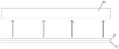
图2为本发明具体实施例所述背光模组的结构示意图;2 is a schematic structural view of the backlight module according to a specific embodiment of the present invention;
图3为本发明第一实施例所述透明显示装置的结构示意图;3 is a schematic structural diagram of the transparent display device according to the first embodiment of the present invention;
图4为本发明第一实施例所述透明显示装置的结构示意图;4 is a schematic structural view of the transparent display device according to the first embodiment of the present invention;
图5为本发明具体实施例所述透明显示装置中,所述显示面板第一种结构的示意图;5 is a schematic diagram of the first structure of the display panel in the transparent display device according to the specific embodiment of the present invention;
图6为本发明具体实施例所述透明显示装置中,所述显示面板第二种结构的示意图。FIG. 6 is a schematic diagram of a second structure of the display panel in the transparent display device according to the specific embodiment of the present invention.
具体实施方式Detailed ways
为使本发明的实施例要解决的技术问题、技术方案和优点更加清楚,下面将结合附图及具体实施例进行详细描述。In order to make the technical problems, technical solutions and advantages to be solved by the embodiments of the present invention clearer, the following will describe in detail with reference to the drawings and specific embodiments.
如图2为本发明具体实施例所述背光模组的结构示意图,图3为采用本发明所述背光模组的透明显示装置第一实施例的结构示意图。FIG. 2 is a schematic structural diagram of a backlight module according to a specific embodiment of the present invention, and FIG. 3 is a schematic structural diagram of a first embodiment of a transparent display device using the backlight module according to the present invention.
参阅图2和图3,所述背光模组包括:Referring to Figure 2 and Figure 3, the backlight module includes:
光源10,用于提供一自然光;The
用于将所述光源10所发出自然光转换为线偏振光的光转换元件20,所述光转换元件设置于所述光源10的一侧。A
利用所设置的光转换元件20,可以为透明显示装置的显示面板30提供线偏振光,使到达显示面板30的所有入射光均能够用于图像显示,从而大大提高显示面板30的光透过率,以提高显示面板的透明效果。The
本发明具体实施例中,所述光转换元件20可以包括一起偏器,具体地,该起偏器可以为偏光片、尼科尔棱镜或渥氏棱镜,其中偏光片或尼科尔棱镜为通常的用于将自然光转换为线偏振光的光学器件,本领域技术人员应该会了解通过偏光片或尼科尔棱镜将自然光转换为线偏振光的原理及结构,在此不详细描述。In a specific embodiment of the present invention, the
此外,所述光转换元件20也可以包括一反射型偏光增亮膜片(DBEF,Dual-Brightness Enhancement Film),能够将自然光转换为两个振动方向相互垂直的线偏振光。通常DBEF采用多层棱镜膜构成,所设置的棱镜膜能够使沿第一方向振动的线偏振光通过,使沿第二方向(与第一方向垂直)振动的线偏振光被反射,从而能够将光线转换为振动方向相垂直的第一偏振光和第二偏振光。In addition, the
本领域技术人员应该能够了解DBEF将自然光转换为振动方向相互垂直的线偏振光的原理与设置结构,在此不作详细描述。Those skilled in the art should be able to understand the principle and configuration of the DBEF for converting natural light into linearly polarized light whose vibration directions are perpendicular to each other, and will not be described in detail here.
此外,本发明所述背光模组中,所述光转换元件20可以与光源10贴合连接,使光源10所发出自然光全部入射至光转换元件20,以充分利用光源10所发出光线;此外,所述光转换元件20与光源10之间也可以设置导光板,光源10所发出自然光传输至导光板内,光转换元件20与导光板的出光面贴合连接,或者位于导光板出光面的一侧,使导光板上的光能够全部传输进入光转换元件20,转换为线偏振光。In addition, in the backlight module of the present invention, the
本发明另一方面提供一种透明显示装置,结合图2与图3,包括背光模组和呈透明的显示面板30,所述背光模组包括光源10,用于为所述显示面板提供入射光,还包括:用于将所述光源所发出自然光转换为线偏振光的光转换元件20,所述光转换元件20设置于所述光源10向所述显示面板30发射入射光的一侧,经转换后的所述线偏振光入射至所述显示面板30。Another aspect of the present invention provides a transparent display device, which includes a backlight module and a
本发明所述背光模组应用于透明显示装置时,如图3所述透明显示装置的第一种实施例结构,所述透明显示装置包括上述结构的背光模组和呈透明的显示面板30,该透明显示装置形成为一箱体结构,其中显示面板30设置于箱体一侧的外表面,背光模组设置于箱体的内部,且位于显示面板20的两侧。箱体内部可以设置有用于向外展示的物品40,透过透明的显示面板30,可以观看到该物品40。When the backlight module of the present invention is applied to a transparent display device, the structure of the first embodiment of the transparent display device as shown in FIG. 3 , the transparent display device includes the backlight module of the above structure and a
图3所示透明显示装置,采用本发明具体实施例的背光模组,利用所设置的光转换元件20,可以为透明显示装置的显示面板30提供线偏振光。经过光转换元件20转换后的线偏振光,一部分直接进入显示面板30,另一部分照射到箱体内的物品40上,被物品40所反射后进入显示面板30,而到达显示面板30的线偏振光可以无吸收的进入显示面板30,用于图像显示。因此,能够大大提高显示面板30的光透过率,以提高显示面板的透明效果。The transparent display device shown in FIG. 3 can provide linearly polarized light for the
如图4为本发明所述透明显示装置的第二种实施例结构。在第二实施例中,所述背光模组相对于显示面板30设置于后方位置,并非位于显示面板30的两侧。与第一实施例相同,所述背光模组包括光源10和用于将光源10所发出自然光转换为线偏振光的光转换元件20,利用所设置的光转换元件20,为显示面板30提供线偏振光,到达显示面板30的所有线偏振光可以全部进入显示面板30,用于图像显示,因此能够大大提高显示面板30的光透光率,提高显示面板30的透明效果。FIG. 4 shows the structure of the second embodiment of the transparent display device of the present invention. In the second embodiment, the backlight module is disposed behind the
具有本发明所述背光模组的所述透明显示装置的结构并不限于上述的两种实施例,如也可以采用将背光模组设置于显示面板前方的结构制作透明显示装置。本领域技术人员应该可以根据本发明的技术思想对所述透明显示装置的结构作出改动,在此不一一描述。The structure of the transparent display device with the backlight module of the present invention is not limited to the above-mentioned two embodiments, for example, the transparent display device can also be manufactured by adopting a structure in which the backlight module is arranged in front of the display panel. Those skilled in the art should be able to make changes to the structure of the transparent display device according to the technical idea of the present invention, which will not be described here one by one.
图5为本发明具体实施例所述透明显示装置中,所述显示面板30第一种结构的示意图。具体地,所述显示面板包括阵列基板31、彩膜基板32以及设置于阵列基板31和彩膜基板32之间的液晶层33。其中所述彩膜基板32相对于液晶层33的另一侧设置第一偏光片321,阵列基板31相对于液晶层33的另一侧设置第二偏光片311,利用第二偏光片311使入射至显示面板30的线偏振光转换为显示面板30实现显示效果所需要的线偏振光,利用第一偏光片321来控制线偏振光在显示面板30上的通过与否。FIG. 5 is a schematic diagram of a first structure of the
此外具体地,第一偏光片321的透光轴角度与第二偏光片311的透光轴角度相垂直,经过背光模组光转换元件20后发出的线偏振光的方向与第二偏光片311的透光轴角度相同(如为图3所示形成为垂直于纸面向里的方向),以使得从光转换元件20发出的线偏振光能够透过第二偏光片311传输进入显示面板内,也即当光转换元件20为偏光片时,光转换元件20的透光轴方向与第一偏光片321的透光轴方向相垂直,与第二偏光片311的透光轴方向相平行。In addition, specifically, the angle of the transmission axis of the
图6为本发明具体实施例所述透明显示装置中,所述显示面板30的第二种结构的示意图。由于采用本发明所述背光模组,入射至显示面板30的光已经为线偏振光,因此相对于显示面板30的第一种结构,阵列基板31相对于所述液晶层33的另一侧可以不需设置偏光片,而只需在彩膜基板32相对液晶层33的另一侧设置第一偏光片321,用来控制光线通过与否。FIG. 6 is a schematic diagram of a second structure of the
采用该种实施结构时,相对于现有技术的显示面板,由于减少了一层偏光片的设置,因此能够更进一步达到提高透明显示效果的目的。When this implementation structure is adopted, compared with the display panel in the prior art, since the arrangement of one layer of polarizer is reduced, the purpose of improving the transparent display effect can be further achieved.
此外,该实施例中,为实现图像显示,经过背光模组光转换元件20后发出的线偏振光的方向与第一偏光片321的透光轴角度相垂直,也即当光转换元件20为偏光片时,光转换元件20的透光轴方向与第一偏光片321的透光轴方向相垂直。In addition, in this embodiment, in order to realize image display, the direction of the linearly polarized light emitted after passing through the
本发明具体实施例所述背光模组及透明显示装置,利用所设置的光转换元件,可以为透明显示装置的显示面板提供线偏振光,使到达显示面板的所有入射光均能够用于图像显示,从而大大提高显示面板的光透过率,以提高显示面板的透明效果。The backlight module and the transparent display device described in the specific embodiments of the present invention can provide linearly polarized light for the display panel of the transparent display device by using the light conversion element provided, so that all incident light reaching the display panel can be used for image display , thereby greatly increasing the light transmittance of the display panel, so as to improve the transparency effect of the display panel.
以上所述是本发明的优选实施方式,应当指出,对于本技术领域的普通技术人员来说,在不脱离本发明所述原理的前提下,还可以作出若干改进和润饰,这些改进和润饰也应视为本发明的保护范围。The above description is a preferred embodiment of the present invention, it should be pointed out that for those of ordinary skill in the art, without departing from the principle of the present invention, some improvements and modifications can also be made, and these improvements and modifications can also be made. It should be regarded as the protection scope of the present invention.
Claims (10)
Priority Applications (1)
| Application Number | Priority Date | Filing Date | Title |
|---|---|---|---|
| CN201310713391.7ACN103698939A (en) | 2013-12-20 | 2013-12-20 | Backlight module and transparent display device |
Applications Claiming Priority (1)
| Application Number | Priority Date | Filing Date | Title |
|---|---|---|---|
| CN201310713391.7ACN103698939A (en) | 2013-12-20 | 2013-12-20 | Backlight module and transparent display device |
Publications (1)
| Publication Number | Publication Date |
|---|---|
| CN103698939Atrue CN103698939A (en) | 2014-04-02 |
Family
ID=50360521
Family Applications (1)
| Application Number | Title | Priority Date | Filing Date |
|---|---|---|---|
| CN201310713391.7APendingCN103698939A (en) | 2013-12-20 | 2013-12-20 | Backlight module and transparent display device |
Country Status (1)
| Country | Link |
|---|---|
| CN (1) | CN103698939A (en) |
Cited By (3)
| Publication number | Priority date | Publication date | Assignee | Title |
|---|---|---|---|---|
| CN103995389A (en)* | 2014-05-04 | 2014-08-20 | 京东方科技集团股份有限公司 | Transparent display device |
| WO2017118167A1 (en)* | 2016-01-05 | 2017-07-13 | 京东方科技集团股份有限公司 | Transparent show window display device |
| CN116594183A (en)* | 2023-06-01 | 2023-08-15 | 浙江炽云科技有限公司 | Head-up display device and design method thereof |
Citations (4)
| Publication number | Priority date | Publication date | Assignee | Title |
|---|---|---|---|---|
| CN102236203A (en)* | 2010-04-23 | 2011-11-09 | 乐金显示有限公司 | Transparent display device |
| CN202132807U (en)* | 2011-07-14 | 2012-02-01 | 京东方科技集团股份有限公司 | Backlight Module and LCD Display |
| CN102608808A (en)* | 2012-04-01 | 2012-07-25 | 青岛海信电器股份有限公司 | Transparent display device and electronic device applying transparent display device |
| CN202747156U (en)* | 2012-08-29 | 2013-02-20 | 京东方科技集团股份有限公司 | Backlight module and liquid crystal display device |
- 2013
- 2013-12-20CNCN201310713391.7Apatent/CN103698939A/enactivePending
Patent Citations (4)
| Publication number | Priority date | Publication date | Assignee | Title |
|---|---|---|---|---|
| CN102236203A (en)* | 2010-04-23 | 2011-11-09 | 乐金显示有限公司 | Transparent display device |
| CN202132807U (en)* | 2011-07-14 | 2012-02-01 | 京东方科技集团股份有限公司 | Backlight Module and LCD Display |
| CN102608808A (en)* | 2012-04-01 | 2012-07-25 | 青岛海信电器股份有限公司 | Transparent display device and electronic device applying transparent display device |
| CN202747156U (en)* | 2012-08-29 | 2013-02-20 | 京东方科技集团股份有限公司 | Backlight module and liquid crystal display device |
Cited By (5)
| Publication number | Priority date | Publication date | Assignee | Title |
|---|---|---|---|---|
| CN103995389A (en)* | 2014-05-04 | 2014-08-20 | 京东方科技集团股份有限公司 | Transparent display device |
| CN103995389B (en)* | 2014-05-04 | 2016-08-24 | 京东方科技集团股份有限公司 | A kind of transparent display |
| WO2017118167A1 (en)* | 2016-01-05 | 2017-07-13 | 京东方科技集团股份有限公司 | Transparent show window display device |
| US10660457B2 (en) | 2016-01-05 | 2020-05-26 | Boe Technology Group Co., Ltd. | Transparent window display apparatus |
| CN116594183A (en)* | 2023-06-01 | 2023-08-15 | 浙江炽云科技有限公司 | Head-up display device and design method thereof |
Similar Documents
| Publication | Publication Date | Title |
|---|---|---|
| JP5027734B2 (en) | Video viewing equipment | |
| JP2006139283A (en) | Liquid crystal display and manufacturing method thereof | |
| JP3197142U (en) | Mirror display panel | |
| TW201137458A (en) | Transparent display device | |
| CN104375325B (en) | A kind of transparent display | |
| CN103838029B (en) | A kind of display unit | |
| KR100945359B1 (en) | LCD Display | |
| WO2014059756A1 (en) | Liquid crystal display device, special glasses and displaying system | |
| TWI506310B (en) | Liquid crystal display device | |
| JP2017027004A5 (en) | ||
| CN107505773B (en) | Backlight module and display device | |
| TW200701475A (en) | Liquid crystal display and method of manufacturing of a tft array panel of the same | |
| KR101644518B1 (en) | Transparent display device and method for displaying using the same | |
| CN105445999A (en) | Dual-face display | |
| CN103353682B (en) | Display floater and transparent display | |
| US9964785B2 (en) | Display device | |
| WO2010047144A1 (en) | Liquid crystal display apparatus | |
| US9658387B2 (en) | Double-screen display device and double-screen displaying method | |
| CN103698939A (en) | Backlight module and transparent display device | |
| US20150153503A1 (en) | Backlight module and transparent display device comprising the same | |
| CN103676305A (en) | Double-sided liquid crystal display | |
| CN104240608A (en) | Display device | |
| JP2004354818A (en) | Display device | |
| CN205049840U (en) | Double-sided display module with optical functional film | |
| CN212181215U (en) | Backlight module and liquid crystal display device |
Legal Events
| Date | Code | Title | Description |
|---|---|---|---|
| C06 | Publication | ||
| PB01 | Publication | ||
| C10 | Entry into substantive examination | ||
| SE01 | Entry into force of request for substantive examination | ||
| RJ01 | Rejection of invention patent application after publication | Application publication date:20140402 | |
| RJ01 | Rejection of invention patent application after publication |