CN1036872A - interlocking zoom device - Google Patents
interlocking zoom deviceDownload PDFInfo
- Publication number
- CN1036872A CN1036872ACN89102152ACN89102152ACN1036872ACN 1036872 ACN1036872 ACN 1036872ACN 89102152 ACN89102152 ACN 89102152ACN 89102152 ACN89102152 ACN 89102152ACN 1036872 ACN1036872 ACN 1036872A
- Authority
- CN
- China
- Prior art keywords
- zoom
- interlocking
- cameras
- focal length
- camera
- Prior art date
- Legal status (The legal status is an assumption and is not a legal conclusion. Google has not performed a legal analysis and makes no representation as to the accuracy of the status listed.)
- Expired - Lifetime
Links
- 230000003287optical effectEffects0.000claimsdescription14
- 238000001514detection methodMethods0.000claimsdescription12
- 230000001681protective effectEffects0.000claims1
- 238000003384imaging methodMethods0.000abstractdescription23
- 230000008859changeEffects0.000abstractdescription17
- 238000000034methodMethods0.000description24
- 230000007246mechanismEffects0.000description15
- 230000008569processEffects0.000description8
- 238000010586diagramMethods0.000description6
- 230000005540biological transmissionEffects0.000description3
- 238000005286illuminationMethods0.000description3
- 238000003491arrayMethods0.000description2
- 230000006698inductionEffects0.000description2
- 238000003825pressingMethods0.000description2
- 241000669298Pseudaulacaspis pentagonaSpecies0.000description1
- 241000872198Serjania polyphyllaSpecies0.000description1
- 239000003990capacitorSubstances0.000description1
- 230000007423decreaseEffects0.000description1
- 230000005611electricityEffects0.000description1
- 230000006870functionEffects0.000description1
- 230000003760hair shineEffects0.000description1
- 230000001939inductive effectEffects0.000description1
- 230000010354integrationEffects0.000description1
- 238000004020luminiscence typeMethods0.000description1
- 230000014759maintenance of locationEffects0.000description1
- 238000004519manufacturing processMethods0.000description1
- 238000004321preservationMethods0.000description1
- 238000003860storageMethods0.000description1
- 230000001360synchronised effectEffects0.000description1
Images


Classifications
- H—ELECTRICITY
- H04—ELECTRIC COMMUNICATION TECHNIQUE
- H04N—PICTORIAL COMMUNICATION, e.g. TELEVISION
- H04N13/00—Stereoscopic video systems; Multi-view video systems; Details thereof
- H04N13/20—Image signal generators
- H04N13/204—Image signal generators using stereoscopic image cameras
- H04N13/239—Image signal generators using stereoscopic image cameras using two 2D image sensors having a relative position equal to or related to the interocular distance
- G—PHYSICS
- G03—PHOTOGRAPHY; CINEMATOGRAPHY; ANALOGOUS TECHNIQUES USING WAVES OTHER THAN OPTICAL WAVES; ELECTROGRAPHY; HOLOGRAPHY
- G03B—APPARATUS OR ARRANGEMENTS FOR TAKING PHOTOGRAPHS OR FOR PROJECTING OR VIEWING THEM; APPARATUS OR ARRANGEMENTS EMPLOYING ANALOGOUS TECHNIQUES USING WAVES OTHER THAN OPTICAL WAVES; ACCESSORIES THEREFOR
- G03B35/00—Stereoscopic photography
- G03B35/08—Stereoscopic photography by simultaneous recording
- G—PHYSICS
- G03—PHOTOGRAPHY; CINEMATOGRAPHY; ANALOGOUS TECHNIQUES USING WAVES OTHER THAN OPTICAL WAVES; ELECTROGRAPHY; HOLOGRAPHY
- G03B—APPARATUS OR ARRANGEMENTS FOR TAKING PHOTOGRAPHS OR FOR PROJECTING OR VIEWING THEM; APPARATUS OR ARRANGEMENTS EMPLOYING ANALOGOUS TECHNIQUES USING WAVES OTHER THAN OPTICAL WAVES; ACCESSORIES THEREFOR
- G03B3/00—Focusing arrangements of general interest for cameras, projectors or printers
- G—PHYSICS
- G03—PHOTOGRAPHY; CINEMATOGRAPHY; ANALOGOUS TECHNIQUES USING WAVES OTHER THAN OPTICAL WAVES; ELECTROGRAPHY; HOLOGRAPHY
- G03B—APPARATUS OR ARRANGEMENTS FOR TAKING PHOTOGRAPHS OR FOR PROJECTING OR VIEWING THEM; APPARATUS OR ARRANGEMENTS EMPLOYING ANALOGOUS TECHNIQUES USING WAVES OTHER THAN OPTICAL WAVES; ACCESSORIES THEREFOR
- G03B5/00—Adjustment of optical system relative to image or object surface other than for focusing
- H—ELECTRICITY
- H04—ELECTRIC COMMUNICATION TECHNIQUE
- H04N—PICTORIAL COMMUNICATION, e.g. TELEVISION
- H04N13/00—Stereoscopic video systems; Multi-view video systems; Details thereof
- H04N13/20—Image signal generators
- H04N13/296—Synchronisation thereof; Control thereof
- G—PHYSICS
- G03—PHOTOGRAPHY; CINEMATOGRAPHY; ANALOGOUS TECHNIQUES USING WAVES OTHER THAN OPTICAL WAVES; ELECTROGRAPHY; HOLOGRAPHY
- G03B—APPARATUS OR ARRANGEMENTS FOR TAKING PHOTOGRAPHS OR FOR PROJECTING OR VIEWING THEM; APPARATUS OR ARRANGEMENTS EMPLOYING ANALOGOUS TECHNIQUES USING WAVES OTHER THAN OPTICAL WAVES; ACCESSORIES THEREFOR
- G03B2205/00—Adjustment of optical system relative to image or object surface other than for focusing
- G03B2205/0046—Movement of one or more optical elements for zooming
- G—PHYSICS
- G03—PHOTOGRAPHY; CINEMATOGRAPHY; ANALOGOUS TECHNIQUES USING WAVES OTHER THAN OPTICAL WAVES; ELECTROGRAPHY; HOLOGRAPHY
- G03B—APPARATUS OR ARRANGEMENTS FOR TAKING PHOTOGRAPHS OR FOR PROJECTING OR VIEWING THEM; APPARATUS OR ARRANGEMENTS EMPLOYING ANALOGOUS TECHNIQUES USING WAVES OTHER THAN OPTICAL WAVES; ACCESSORIES THEREFOR
- G03B2205/00—Adjustment of optical system relative to image or object surface other than for focusing
- G03B2205/0053—Driving means for the movement of one or more optical element
Landscapes
- Engineering & Computer Science (AREA)
- Multimedia (AREA)
- Signal Processing (AREA)
- Physics & Mathematics (AREA)
- General Physics & Mathematics (AREA)
- Lens Barrels (AREA)
- Testing, Inspecting, Measuring Of Stereoscopic Televisions And Televisions (AREA)
- Stereoscopic And Panoramic Photography (AREA)
- Studio Devices (AREA)
- Length Measuring Devices By Optical Means (AREA)
Abstract
Translated fromChineseDescription
Translated fromChinese本发明是一种用于立体摄象机的联锁变焦装置,该立体摄象机包括两个视频摄象机或类似的装置,具体说本发明提供一种便于执行联锁变焦的联锁变焦装置。The present invention is an interlocking zoom device for a stereo camera comprising two video cameras or the like, and more specifically the present invention provides an interlocking zoom that facilitates the execution of interlocking zooming device.
在日本专利公报62678/1982中公开了一种与本发明有关的联锁变焦装置,图1所示便是一种在公报中所述的具有那种传统的联锁变焦装置典型的摄象装置。In Japanese Patent Publication 62678/1982, a kind of interlocking zoom device related to the present invention is disclosed, and Fig. 1 shows a kind of typical image pickup device with that traditional interlocking zoom device described in the gazette .
在图1的这种带有传统联锁变焦装置的摄象装置中包括:第一和第二摄象机101和102,它们拍下实物116的影像;同步信号发生器117,它产生第一和第二摄象机101和102同步工作的信号;一个信号开关装置118,用于控制第一和第二摄象机101和102输出信号的开关。第一和第二摄象机101和102上分别具有可变焦的第一、第二变焦镜头103和104。第一、第二变焦镜头103和104则分别包括变焦装置105和106,它可以通过改变变焦镜头的焦距来改变被摄物的放大倍数。变焦镜头上还分别具有聚焦装置108和109,通过改变变焦装置105和106来分别调整变焦透镜的焦距。在老式的联锁变焦装置中还有将聚焦装置108和109联锁起来的对焦操作件107,和把变焦装置105,106联锁起来的变焦操作件110。对焦操作件107和变焦操作件110是由人工操作部分41和44操纵的。软的缆线111分别将聚焦装置108、109和对焦操作件107、及变焦装置105、106和变焦操作件110联接起来。Comprise in this image pickup device with traditional interlocking zoom device of Fig. 1: first and
老式的联锁变焦装置是这样工作的:当第一、第二摄象机101、102变焦联锁时,使用者手工操纵变焦操作件110和对焦操作件107的手动部分41和44,同时观察两个摄象机的监视屏(图中未示),这样,用人工的方法调节第一、第二摄象机101、102,使影像的变焦比相匹配。The old-fashioned interlocking zoom device works like this: when the first and
如上所述的这种老式联锁变焦装置中,每次拍摄场景的画面变化时,就要人工调整左右摄象机的变焦镜头。可见,摄象时的操作性很差,以致拍摄一个画面要化费很多时间。In this old-fashioned interlocking zoom device as mentioned above, when the picture of the shooting scene changes every time, the zoom lenses of the left and right cameras will be manually adjusted. It can be seen that the operability when taking pictures is very poor, so that it takes a lot of time to take a picture.
另外,这种传统的联锁变焦装置的两个变焦镜头的调整范围也很有限。特别是,第一,第二变焦镜头不一定制造得完全一样,而且,既使将它们制造得完全相同,它们也不一定是以同样的方法装在摄象机机体上,在变焦镜头分别装在摄象机上时,所用的各种部件也不是全相同的。由于变焦镜头通常是由直流电机带动的,所以,如果装在摄象机上的变焦镜头各部分不完全相同,就很难进行统一的操作控制。此外,在拍摄和放置这对摄象机的过程中,很难将其置于恒定的外界条件中,在这种情况下,使用者很难靠手动调整这两个摄象机成像的大小,尤其在双镜头摄象机中,根据变焦镜头变焦比的变化,靠手工操纵对焦和变焦装置,同步调整左右摄象机的成像大小是很困难的。In addition, the adjustment range of the two zoom lenses of this traditional interlocking zoom device is also very limited. In particular, the first and second zoom lenses are not necessarily made exactly the same, and even if they are made exactly the same, they are not necessarily installed on the camera body in the same way. When on a video camera, the various components used are not all the same. Since the zoom lens is usually driven by a DC motor, if the various parts of the zoom lens mounted on the video camera are not identical, it is difficult to perform unified operation and control. In addition, in the process of shooting and placing the pair of cameras, it is difficult to place them in constant external conditions. In this case, it is difficult for the user to manually adjust the size of the images of the two cameras. Especially in a double-lens camera, according to the variation of the zoom ratio of the zoom lens, it is very difficult to synchronously adjust the imaging size of the left and right cameras by manipulating the focusing and zooming devices.
因此,本发明的目的是能够使双筒立体摄象机的联锁变焦装置,在二个变焦镜头的变焦比改变时,其左右摄象机成像大小便于调整。Therefore, the purpose of the present invention is to be able to make the interlocking zoom device of binocular stereo camera, when the zoom ratio of two zoom lenses changes, the imaging size of the left and right cameras is easy to adjust.
本发明的另一个目的是要使双筒立体摄象机的联锁变焦装置每次变焦时,左右两个像大小相同。Another object of the present invention is to make the interlocking zoom device of the binocular stereo camera zoom each time, and the left and right images have the same size.
本发明还有一个目的是使联锁变焦装置中,由左右变焦镜头所成的两个像可以容易地调整到一样大小。Yet another object of the present invention is to make the two images formed by the left and right zoom lenses easily adjusted to the same size in the interlocking zoom device.
本发明的最后一个目的就是使联锁变焦装置变焦比的改变比较容易地进行。A final object of the invention is to make the change of the zoom ratio of the interlocking zoom device relatively easy.
本发明是一种同步操作一对摄象机的联锁变焦装置,这对摄象机彼此分离,拍摄同一实物,其中一个摄象机中有第一变焦装置,另一个摄象机中有第二变焦装置,所述的联锁变焦装置包括改变第一变焦装置焦距的第一焦距变焦装置,改变第二变焦装置焦距的第二焦距变焦装置,和用电源作动力同步驱动第一焦距变焦装置和第二焦距变焦装置的变焦装置驱动器。在本发明的联锁变焦装置中,装在左右两个摄象机里的第一、二焦距变焦装置是电源同步驱动的,这样,当其中一个变焦镜头的焦距改变时,靠电动方式,使另一个变焦镜头的焦距也同步变化。因此,当两个变焦镜头的变焦比改变时,在双筒立体摄象机的联锁变焦装置中很容易调整其左右成像的大小。The present invention is an interlocking zoom device for synchronously operating a pair of cameras. The pair of cameras are separated from each other and shoot the same real object. One camera has a first zoom device, and the other camera has a second zoom device. Two zooming devices, the interlocking zooming device includes a first focal length zooming device for changing the focal length of the first zooming device, a second focal length zooming device for changing the focal length of the second zooming device, and synchronously driving the first focal length zooming device with a power supply and a zoom device driver for the second focal length zoom device. In the interlocking zoom device of the present invention, the first and second focal length zoom devices installed in the left and right cameras are synchronously driven by power supply. The focal length of the other zoom lens also changes synchronously. Therefore, when the zoom ratio of the two zoom lenses is changed, it is easy to adjust the size of the left and right imaging in the interlocking zoom device of the binocular stereo camera.
在本发明的最佳实施例中,联锁变焦装置还包括图像放大倍数调整装置,调整第一,第二变焦镜头在望远端所成第一图像的大小,和第一、第二变焦镜头在广角端所成第二图像的大小。由于联锁变焦装置中有如上的联锁变焦机构,所以可分别在望远端和广角端将成像的大小调整到相同的程度。每个摄象机在广角端和望远端间变焦时,也可形成大小相同的像。由此,双筒立体摄象机的联锁变焦装置总是可以使左右摄象机的成像大小相同。In a preferred embodiment of the present invention, the interlocking zoom device also includes an image magnification adjustment device, which adjusts the size of the first image formed by the first and second zoom lenses at the telephoto end, and the first and second zoom lenses at the telephoto end. The size of the second image formed at the wide-angle end. Since the above-mentioned interlocking zoom mechanism is included in the interlocking zoom device, the size of the imaging can be adjusted to the same degree at the telephoto end and the wide-angle end respectively. Each camera can also form an image of the same size when zooming between the wide-angle end and the telephoto end. Thus, the interlocking zoom device of the binocular stereo camera can always make the imaging size of the left and right cameras the same.
在本发明的实施例中,第一、第二变焦镜头的变焦装置包括:用电力驱动第一、第二变焦镜头在望远端和广角端间运动的第一、第二变焦镜头驱动装置,而第一、第二变焦镜头驱动装置分别带有脉冲电机联锁变焦装置中的变焦镜头分别由脉冲电机驱动,脉冲信号可以同时送到两个脉冲电机上,以使左右变焦镜头变焦比的变化率相匹配。因此,按照这两个变焦镜头变焦比的变化,很容使两个摄象机成象大小相同。In an embodiment of the present invention, the zooming devices of the first and second zoom lenses include: first and second zoom lens driving devices that drive the first and second zoom lenses to move between the telephoto end and the wide-angle end with electricity, and The first and second zoom lens driving devices are respectively equipped with pulse motors. The zoom lenses in the interlocking zoom device are respectively driven by pulse motors. match. Therefore, according to the change of the zoom ratio of the two zoom lenses, it is easy to make the image size of the two cameras the same.
在下面,结合附图对本发明进行了详细的说明以后,可更清楚地看出本发明上述的、或其它的目的、特点和优点。In the following, after the present invention is described in detail in conjunction with the accompanying drawings, the above-mentioned or other objects, features and advantages of the present invention can be seen more clearly.
图1是两个摄象机的传统拍摄装置;Fig. 1 is the traditional shooting device of two video cameras;
图2是本发明的双筒立体摄象机的主体图;Fig. 2 is the main figure of binocular stereo camera of the present invention;
图3是变焦镜头的具体结构;Fig. 3 is the concrete structure of zoom lens;
图4A至4C是本发明分别在望远端和广角端调整左右摄象机成像大小的第一种结构;4A to 4C are the first structures of the present invention to adjust the imaging size of the left and right cameras at the telephoto end and the wide-angle end respectively;
图5是根据本发明在望远端调整二个摄象机成像大小的第二种结构;Fig. 5 is the second structure that adjusts the imaging size of two cameras at the telephoto end according to the present invention;
图6A和6B至图12A和12B是对使用本发明的端像调整装置的成像大小进行调整的机构;Figures 6A and 6B to Figures 12A and 12B are mechanisms for adjusting the imaging size of the end image adjustment device of the present invention;
图13是本发明联锁变焦装置控制方法的框图;Fig. 13 is a block diagram of the control method of the interlocking zoom device of the present invention;
图14至16分别表示本发明左右摄象机变焦比的变化曲线;Fig. 14 to 16 represent the change curve of zoom ratio of left and right cameras of the present invention respectively;
图17是本发明的变焦环在望远端或广角端定位的特例;Fig. 17 is a special case of the positioning of the zoom ring of the present invention at the telephoto end or the wide-angle end;
图18是图13框图的具体结构;Fig. 18 is the concrete structure of Fig. 13 block diagram;
图19是本发明联锁变焦装置的另一种控制流程图;Fig. 19 is another control flowchart of the interlocking zoom device of the present invention;
图20是本发明的联锁变焦装置控制方法的框图;Fig. 20 is a block diagram of the control method of the interlocking zoom device of the present invention;
图21A和21B是本发明左右两个摄象机调整成像大小的第二个实施例;Fig. 21A and 21B are the second embodiment of adjusting the imaging size of two left and right cameras of the present invention;
图22是本发明图像放大倍数第二种自动调整装置电路结构的框图;Fig. 22 is a block diagram of the second automatic adjustment device circuit structure of the image magnification of the present invention;
图23是图21所示控制装置执行的控制流程图;Fig. 23 is the control flowchart that the control device shown in Fig. 21 executes;
现对本发明的立体摄象装置进行说明。Now, the stereoscopic imaging device of the present invention will be described.
图2是一个立体摄象机的透视图,这个摄象机中使用了本发明的联锁变焦装置。根据本发明,立体摄象机有:拍摄同一实物的左右两个摄象机10a、10b;架持这两个摄象机的三脚架头12;和撑住三脚架头12的三脚架15。左右摄象机10a和10b分别具有:使实物成像的变焦镜头5a、5b;影像记录部分11a和11b,它们将变焦镜头5a、5b的影像记录下来。摄象机10a和10b拍摄同一实物的图像,在该实物的立体影像形成时,联锁变焦装置将以如下所述的方式进行控制,使摄象机10a和10b成像大小相等。Fig. 2 is a perspective view of a stereo camera in which the interlocking zoom device of the present invention is used. According to the present invention, stereoscopic camera has: two left and right video cameras 10a, 10b of photographing same real object; The left and right cameras 10a and 10b respectively have:
实物横向运动时,三脚架头12带着装在其上的摄象机10a、10b一起同步转动。同时,在本实施例中,立体摄象装置的两个摄象机10a、10b还可以各自沿(图2中的)光轴d方向运动。When the object moves laterally, the
图3进一步说明了图2中的每个变焦镜头5a、5b的具体结构。参见图3,每个变焦镜头5a、5b中包括变焦镜头组52,以改变变焦比;一组前透镜51,将变焦镜头52中所成的像聚焦成点像;变焦装置100使变焦镜头组52相互联锁,使前透镜组51联锁,并使其依同一方式运动。这样在变焦比改变时,便可调整焦点。变焦装置100包括一个能使变焦镜头组52旋转的传动齿轮53,旋转是由镜头筒54上的螺旋齿轮实现的;变焦马达55驱动传动齿轮53;小齿轮56将变焦马达55的驱动力传给传动齿轮53。FIG. 3 further illustrates the specific structure of each
变焦镜头5a和5b是按如下方式工作的。当每个变焦镜头5a、5b使所摄实物的变焦比变化时,一个预定的信号便输入到变焦马达55中,变焦马达55根据该信号正向或反向旋转,通过小齿轮56带动旋转齿轮53随之正向或反向旋转,这样,变焦镜头组52便沿着预定的方向运动。The
由于变焦马达55是(如下所述的)步进电机或一般的直流电机,所以旋转的量可以得到准确的控制。依此法,变焦镜头组52焦距的改变可使图像的大小发生变化,同时,前镜头组51由预定的聚焦装置(图中未示)控制。这样,就在摄象机10a、10b的记录部分11a、11b上形成了一个聚焦的像。Since the
图4A是变焦镜头5a、5b的透视图,该图说明了本发明的联锁变焦装置。图4A在说明变焦镜头5a、5b时,只画出了与联锁变焦装置有关的部分。Fig. 4A is a perspective view of the
参见图4A,在变焦镜头5a、5b上分别具有变焦镜头52的凹槽,可使变焦镜头从广角端到望远端移动1长度,变焦镜头的运动是通过变焦环3沿镜头筒54上的筒形凸轮2的凸轮槽旋转得到的。变焦环挡块4装在变焦环3的一端。变焦环挡块4的运动由框20上的孔调整,以使镜头筒54一端的变焦环(后称变焦环框)运动,特别是当变焦镜头组52在图4所示的长度上运动时,变焦环3则在图4A上由A到B的弧长γ上旋转。Referring to Fig. 4A, there are grooves for the
本发明的联锁变焦装置中有:端像调整装置,以使左右变焦镜头分别在望远端和广角端形成的像大小相同;影像放大倍数自动调整装置,它自动适应在望远端和广角端间图像大小的变化速度。The interlocking zoom device of the present invention includes: an end image adjustment device, so that the images formed by the left and right zoom lenses at the telephoto end and the wide-angle end are of the same size; How fast the image size changes.
有两类方法可以使变焦镜头5a、5b分别在望远端和广角端形成同样大小的像;使图像在望远端和广角端间变化时,自动匹配成像大小的变化速度。其方法如下所述。There are two types of methods to make the
首先说明使变焦镜头分别在望远端和广角端形成同样大小的端像调整装置。First, an end image adjustment device for making the zoom lens have the same size at the telephoto end and the wide-angle end will be described.
(1)端像调整装置的第一个实施例:(1) The first embodiment of the end image adjustment device:
图4A至4C说明了本发明使左右变焦镜头分别在望远端和广角端形成同样大小图像的方法。4A to 4C illustrate the method of the present invention to make the left and right zoom lenses respectively form images of the same size at the telephoto end and the wide-angle end.
图4B是沿图4A中的ⅣB-ⅣB线的平面图。在图4B中,望远端有调整挡块6,广角端有调整挡块7,分别调整变焦环3的旋转量,挡块6、7是设置在变焦环框20的孔的一端上。在望远端处的调整挡块6和广角端处的调整挡块7上设有长孔8a和9a,望远端处的调整挡块6和广角端处的调整挡块7的位置是靠调节长孔8a和9a中的调整螺钉8和9的位置来精确调整的。Fig. 4B is a plan view taken along line IVB-IVB in Fig. 4A. In FIG. 4B , there is an
图4C是沿图4A中的ⅣC-ⅣC线的剖面图。在图4C中,变焦环挡块4可在望远端处的调整挡块6和广角端处的挡块7间运动。具体说就是使变焦环3在望远端处的调整挡块6和广角端处的挡块7间运动。Fig. 4C is a sectional view along the line IVC-IVC in Fig. 4A. In FIG. 4C , the
用调整挡块调整左右两个摄象机成像大小的方法如下:在调整两个摄象机分别在望远端和广角端成像大小时,两个摄象机所成的像显示在显示屏上(图中未示出)。调整望远端处的调整挡块6和广角端处的调整挡块7的位置,使两个摄象机分别在望远端、广角端在显示屏上显示出大小相同的成像。调整好了望远端处调整挡块6和广角端处的调整挡块7的位置后,将调整螺钉8和9拧紧,由此固定望远端处的调整挡块6和广角端处的调整挡块7的位置。The method of adjusting the imaging size of the left and right cameras with the adjustment block is as follows: When adjusting the imaging size of the two cameras at the telephoto end and the wide-angle end respectively, the images formed by the two cameras will be displayed on the display screen ( not shown in the figure). Adjust the positions of the
(2)端像调整装置的第二个实施例:(2) The second embodiment of the end image adjustment device:
现将本发明分别在望远端和广角端使成像大小相同的图像调整装置的第二实施例进行描述。图5是图2所示三脚架头12的立体图,为便于理解,未将左右两个摄象机10a和10b画在其上。三脚架头12上有固定右摄象机10a的固定螺钉13a,固定左摄象机0b的固定螺钉13b,以及可使摄象机10a、10b沿光轴方向运动的滑槽12a、12b。Now, the second embodiment of the image adjustment device of the present invention which makes the imaging size the same at the telephoto end and the wide-angle end will be described. FIG. 5 is a perspective view of the
在根据本发明第二实施例利用端像调整装置调整摄象机10a、10b成像大小时,将摄象机10a、10b中的任一个固定,而另一个摄象机则沿槽12a或12b运动,这样,变焦镜头5a、5b即可分别在广角端和望远端形成同样大小的影像,完成这一步骤后,用固定螺钉13a和13b将摄象机固定在三脚架头12上,以使摄象机10a和10b的位置固定。同时,望远端(或广角端)和广角端(或望远端)成像的大小用图4A所示第一实施例的端像调整装置进行调整。According to the second embodiment of the present invention, when using the end image adjusting device to adjust the imaging size of the cameras 10a, 10b, any one of the cameras 10a, 10b is fixed, while the other camera moves along the
现在参照图6A、6B到12A、12B具体说明使用本发明上述第一、第二实施例的端像调整爸茫髡抖撕凸憬嵌舜λ上竦木咛宸椒āM?A和6B表明了用本发明第一实施例的端像调整装置调整成像大小的方法。图6A表示的是右变焦镜头5a,图6B则对应的是左变焦镜头5b(图6A、6B中的A、B分别与右、左变焦镜头5a,5b相对应)。图4A所示的调整挡块6和7分别设在每个摄象机变焦环框20的广角端和望远端(调整挡块6和7在后面被称为调整机构14)。Now referring to Figs. 6A, 6B to 12A, 12B, the end image adjustment method using the above-mentioned first and second embodiments of the present invention will be described in detail. and 6B show the method of adjusting the image size by the end image adjusting device of the first embodiment of the present invention. Figure 6A shows the
图7A和7B表明了用本发明第一实施例所述的端像调整装置的另一种调整机构。在图7A和7B中,图4A所述的调整挡块6和7只分别装在一个摄象机变焦环框20的广角端和望远端处,而另一个摄象机的变焦环框20上则没有装调整机构14。7A and 7B show another adjustment mechanism using the end image adjustment device according to the first embodiment of the present invention. In FIGS. 7A and 7B, the adjustment blocks 6 and 7 described in FIG. 4A are only installed at the wide-angle end and the telephoto end of the
在图8A和8B中,一个变焦镜头上变焦环框20的广角端装有图4A所示的调整机构14,而另一个变焦镜头的变焦环框20则在望远端上装有图4A所示的调整机构。8A and 8B, the wide-angle end of the
图10A和10B所示是将本发明第一、第二实施例组合在一起,用第(2)种方法调整成像大小的机构。图9A和9B中,只在一个摄象机变焦环框20的望远端上装有图4A所示的调整机构14,以使左右两个摄象机成像大小相同。在图5所示前后方向上,调整机构将摄象机机体移动X距离,即可调整广角端的成像。这样在广角端或望远端左右两个摄象机所成的像大小相同。与之相反,在图10A和图10B中,在图5所示前后方向上,调整机构使摄象机机体移动距离Y,即可调整望远端的成像,图4A所示的调整左右成像相同的调整机构14装在变焦环框20的广角端,这样也可以保证在广角端和望远端两个摄象机均能形成相同大小的像。Figures 10A and 10B show the combination of the first and second embodiments of the present invention, and use the (2) method to adjust the imaging size. Among Figs. 9A and 9B, the
在图11A、11B和图12A、12B中,一个摄象机变焦环框20的望远端(或广角端)上设有图4A所述的调整机构14,而另一个摄象机上则设有可使摄象机机体沿图5所示方向前后运动的机构,这样也可确保在广角端和望远端,左右摄象机能形成大小相同的影像。In Figs. 11A, 11B and Figs. 12A, 12B, the telephoto end (or wide-angle end) of the
现在说明本发明的影像放大倍数自动调整装置,该装置可以根据变焦比自动将变焦镜头5a和5b上所成的像调整到相同大小。本发明的影像放大倍数自动调整装置有二个实施例。第一个实施例是用脉冲电机作为变焦电机的。而第二个实施例采用的是其它电机而不是脉冲电机作为变焦电机,如使用直流电机等。Now, the image magnification automatic adjustment device of the present invention is described, which can automatically adjust the images formed on the
(3)影像放大倍数自动调整装置的第一实施例:(3) The first embodiment of the image magnification automatic adjustment device:
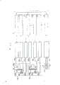
图13是本发明第一实施例的影像放大倍数自动调整装置的框图。参照图13,在该图所示的本发明影像放大倍数自动调整装置包括:拍摄同一实物的左右两个变焦镜头5a和5b;左右两个马达驱动器23a和23b,它们分别向左右两个变焦镜头5a和5b输出驱动信号,控制部分20向马达驱动器23a和23b输出控制信号,用以分别驱动变焦镜头5a和5b;命令控制部分20开始变焦的变焦开关27;还有一个复位开关16,它能使控制部分20清零。变焦镜头5a、5b上分别包括变焦环3a和3b,它们可以通过改变变焦镜头凹槽的焦距来改变成像的大小,变焦马达55a,55b则分别使变焦环3a和3b转动(如图3)。从马达驱动器23a和23b输出的变焦马达驱动信号分别送到变焦马达55a和55b上。在本发明的第一实施例中,变焦马达55a和55b均为脉冲电机。控制部分20包括一个能控制联锁变焦的中央处理单元(CPU)17,存贮预定数据的只读存贮器(ROM)18和随机存贮器(RAM)25;及保持RAM25中所存数据的电池26。变焦开关27上有三个触点a、b和c。与触点a接触时,各变焦镜头的焦距移向望远端;与触点c接触时,则移向广角端;而当接触b点时,便停止工作。图中B表示电源。FIG. 13 is a block diagram of an automatic adjustment device for image magnification according to the first embodiment of the present invention. With reference to Fig. 13, the image magnification automatic adjustment device of the present invention shown in this figure includes: two left and
本发明的联锁变焦装置是这样工作的:按下复位开关16后,低电平信号就被输入到CPU17中,CPU17便控制马达驱动器23a和23b,根据ROM18的指令控制的脉冲电机55a和55b的脉冲频率,使变焦环3a和3b随之从广角端向望远端或从望远端向广角端运动。这时,转动左右摄象机所需的脉冲个数由CPU17中的计数器进行计数。同时在广角端和望远端两个变焦镜头形成的两个像与事先已由第一实施例(图4A至4C)中的端像调整装置预先调到的相同大小。The interlocking zoom device of the present invention works like this: after pressing the
图14所示曲线为左右两个摄象机变焦比的变化曲线。The curve shown in Fig. 14 is the variation curve of the zoom ratio of the left and right cameras.
在图14中,脉冲数n和m分别表示两个摄象机中的变焦马达将变焦镜头从广角端转向望远端所施加的脉冲数。In FIG. 14, the pulse numbers n and m respectively indicate the number of pulses applied by the zoom motors in the two cameras to turn the zoom lens from the wide-angle end to the telephoto end.
CPU17沿图14的X轴取值,同时,在Y轴上得到相应的数据,并将其存入RAM25。CPU17根据这些存贮的数据对加到左右摄象机脉冲电机上的脉冲频率进行调整,这样,两个摄象机的脉冲数及变焦比(分别如图15或16所示)大致相当。图15是靠向左摄象机的曲线,图16是靠向右摄象机的曲线。CPU17 takes values along the X-axis of FIG. 14, and at the same time, obtains corresponding data on the Y-axis, and stores them in RAM25. CPU17 adjusts the pulse frequency that is added on the left and right camera pulse motors according to the data of these storages, like this, the pulse number and zoom ratio (respectively shown in Figure 15 or 16) of two cameras are approximately equivalent. Fig. 15 is a curve towards the left camera, and Fig. 16 is a curve towards the right camera.
在图15和16中,曲线5a’(或5b’)是与曲线5a(5b)和5b(5a)相匹配后得到的曲线。In Figs. 15 and 16, the
现举一个计算例子予以说明。在图14中,假设计到脉冲数m和n所需的时间分别为T1和T2由于两个变焦镜头是以同一脉冲频率运动的,所以有:Now give a calculation example to illustrate. In Figure 14, it is assumed that the time required to design the number of pulses m and n is T1 and T2 respectively. Since the two zoom lenses move at the same pulse frequency, there are:
(m)/(T1) = (n)/(T2)(m)/(T1 ) = (n)/(T2 )
此外,如果左右变焦镜头在T1的时间内分别从广角端转到望远端(如图15),则右摄象机的脉冲频率X为:In addition, if the left and right zoom lenses are respectively turned from the wide-angle end to the telephoto end within the time T1 (as shown in Figure 15), the pulse frequency X of the right camera is:
(n)/(X) =T1(n)/(X) = T1
X= (n)/(T1)X= (n)/(T1 )
该计算结果存到RAM25中。既使关上电源,存进去的数据由电池26供给电源,以便保存。The calculation result is stored in RAM25. Even if the power is turned off, the data stored is powered by the
根据上述方法,在左右变焦镜头上形成两个影像的大小便自动调整到了一样大(后称为自动跟踪)。同时,变焦开关27接在触点a上,变焦镜头从广角端到望远端变焦,并将低电平信号加到CPU17的J端。在变焦镜头从望远端变焦回到广角端时,变焦开关27必须接在触点c上,于是就在CPU17的K端加了一个低电平信号。CPU17在K端有低电平信号输入的时间内驱动两个脉冲电机55a和55b,左右两个像能够根据RAM25中存贮的数据(为指数函数数据)调整到一样大。According to the above method, the sizes of the two images formed on the left and right zoom lenses are automatically adjusted to the same size (hereinafter referred to as automatic tracking). Simultaneously, the
现在再来进一步说明图13所示的第一实施例。图17是检测变焦环是否在望远端或广角端的具体方法。图18说明了图13所示第一实施例的一些具体结构,图19是图18的流程图。The first embodiment shown in FIG. 13 will now be further described. FIG. 17 is a specific method for detecting whether the zoom ring is at the telephoto end or the wide-angle end. FIG. 18 illustrates some specific structures of the first embodiment shown in FIG. 13 , and FIG. 19 is a flowchart of FIG. 18 .
在图17中,固定刻度环28是黑色的,其上标有白色的刻度线29。在带有bis的变焦环30上装有可感应白色刻线的感应头31,bis和变焦环30一起运动。当感应头31感应到白色刻线29时,即可确定变焦环30到达望远端或广角端。In FIG. 17 , the fixed
在图13所示的实施例中,当变焦环30从变焦环框的广角端处开始运动和其到达望远端时,感应头31感应到刻线29,便将变焦环30到达望远端的信号输入CPU中。In the embodiment shown in Fig. 13, when the zoom ring 30 starts to move from the wide-angle end of the zoom ring frame and reaches the telephoto end, the induction head 31 senses the
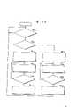
图18和19具体描述了CPU17的工作过程。18 and 19 specifically describe the working process of the
接通复位开关16(第10步),CPU17将具有相同频率的脉冲信号输入到马达驱动器23a和23b上(第12和14步),左右两个摄象机便从广角端运动到了望远端。当两个摄象机的变焦环上所设的感应头31分别检测出其到达了望远端时(第16步),输入马达驱动器23a和23b的脉冲便停止了,此时,相应于两个像发生同样大小变化的脉冲数被计数下来(第18步),计数的结果贮存在RAM25中(第20步),然后计算左右两个像的大小产生相同的变化时,需要加在变焦马达上的脉冲频率和脉冲数(第22步),计算结果贮存在RAM25里(第24步)。接通变焦开关27(第26步),马达驱动器23a和23b上便有加在左右变焦马达上的脉冲信号输入,根据存贮在RAM25中的每次变焦比改变的计算结果,即可使左右两个像大小相同(第28步)。Connect reset switch 16 (the 10th step), CPU17 will have the pulse signal input with identical frequency on the
参照图13,图20表示了这样一个例子:在电源接通时,每次操纵变焦键,不用操作复位开关16,使变焦比改变的情况下,左右两个影像的大小自动调整到大小相同。With reference to Fig. 13, Fig. 20 has shown such an example: when power is turned on, manipulate zoom key at every turn, do not need to operate
在图20中,接通电源后,电阻R1和电容C1积分得到的脉冲信号输入冲息多谐振荡器32,在一个波形形成以后,脉冲信号从“或”门33输入CPU17,其脉宽加大。复位开关16的信号输入到“或”门33的另一输入端。因此,在接通电源或操作复位开关16时,CPU17执行与图13所示的实施例相同的操作过程。同时,由于上述操作过程是在电源接通以后进行的,所以RAM25中不需要用电池来保持数据。In Fig. 20, after the power is turned on, the pulse signal obtained by the integration of the resistorR1 and the capacitorC1 is input into the
下面所述的实施例特别适于在这样的条件下使用:在每次变焦比改变时,用上述装置的双筒立体摄象机的变焦开关的操纵使左右成像的大小相同,由于外界条件的变化、这种机械调整的数值往往不能满足要求。外界条件的影响包括温度、湿度的变化(如在炎热潮湿的地区拍摄后又到了寒冷的地区拍摄),如大风等气象条件的影响及拍摄场景的变化等。The embodiment described below is particularly suitable for use under such conditions: when the zoom ratio changes at every turn, the size of the left and right images is the same with the manipulation of the zoom switch of the binocular stereo camera of the above-mentioned device, due to external conditions Changes, the value of this mechanical adjustment often cannot meet the requirements. The impact of external conditions includes changes in temperature and humidity (such as shooting in a hot and humid area and then shooting in a cold area), such as the impact of meteorological conditions such as strong winds, and changes in shooting scenes.
首先,用图4A至4C所示的机械调整装置,调整在广角端和望远端处变焦镜头左右二个像的大小,左右两个像的大小发生同时变化时的量由图13所示的自动调节装置中的操纵键测出,根据变焦比自动调节两个图象的大小。First, use the mechanical adjustment device shown in Figures 4A to 4C to adjust the size of the left and right images of the zoom lens at the wide-angle end and the telephoto end. The operation key in the automatic adjustment device is detected, and the size of the two images is automatically adjusted according to the zoom ratio.
如果依图4A至4C所示方法的机械调节一次后,该调节值不能满足要求,摄象机的变焦环必须在广角端和望远端重新调节一次。调节值不能满足要求的原因可能是拍摄现场温度的变化,大风或其它类似的情况及拍摄景点变化等。但是变焦环可以调节的范围都是很小的。因此,本发明除了采用图4A至4C的调节机构外,还采用了如图5所示的摄象机位置调节装置,它可以向前或向后移动一个或同时移动两个摄象机的位置。If after the mechanical adjustment according to the method shown in FIGS. 4A to 4C once, the adjustment value cannot meet the requirements, the zoom ring of the video camera must be readjusted at the wide-angle end and the telephoto end. The reason why the adjustment value cannot meet the requirements may be the change of the temperature of the shooting site, strong wind or other similar situations, and the change of the shooting location. But the zoom ring can adjust the range is very small. Therefore, the present invention has also adopted the camera position adjusting device as shown in Figure 5, except that adopting the adjusting mechanism of Fig. 4A to 4C, it can move forward or backward one or move the position of two cameras simultaneously .
既使在如图1所示的机械调整不能令人满意时,采用上述方法,误差也很容易得到修正。该值的修正还可以通过向前或向后移动一个或同时移动两个摄象机的位置,以及用图10所示的由电池26保持在RAM25中的数据来完成。Even when the mechanical adjustment as shown in Fig. 1 is not satisfactory, the error can be easily corrected by the method described above. Correction of this value can also be done by moving one or both cameras forward or backward, and using data held in
(4)图像放大倍数自动调整装置的第二实施例:(4) The second embodiment of the image magnification automatic adjustment device:
图21A所示为本发明图像放大倍数自动调整装置第二实施例主体部分的透视图。图21B是在图21A上沿光轴所在平面的变焦镜头剖视图。图21A与图3所示的变焦镜头的主体图大致相同,由于其中相同的部分用了同一标号表示,故略去对其的描述。Fig. 21A is a perspective view of the main part of the second embodiment of the device for automatically adjusting image magnification according to the present invention. FIG. 21B is a sectional view of the zoom lens along the plane of the optical axis in FIG. 21A . FIG. 21A is substantially the same as the main body view of the zoom lens shown in FIG. 3 , and since the same parts are denoted by the same reference numerals, their descriptions are omitted.
与图3所示的变焦镜头不同的是:图21A所示的变焦镜头包括一个光敏件57,该光敏件57放在变焦镜头组52的前端,沿变焦镜头组52光轴的方向上有一个二极管列阵58。The difference from the zoom lens shown in FIG. 3 is that the zoom lens shown in FIG. 21A includes a
如图21B所示,二极管列阵58上有许多依次排列在一条直线上的微型发光二极管62,隔板59将每个发光二极管62分别隔开,因此二极管列阵58就被分为许多小格61。根据前镜头组51的位置,前镜头组后的发光二极管的数量从零开始增加。沿着光轴方向,镶在镜头筒60下面的光敏件57的长度与该方向上每个小格61的长度一样,这样,光敏件57上只能接受到其相应的小格61中的发光二极管62所发出的光。As shown in Figure 21B, on the
同时,二极管列阵58可以沿着光轴方向作一些运动。这样,在制造光学元件时左右变焦镜头的变焦比上产生的误差可以通过二极管列阵58的运动得到补偿。At the same time, the
图22所示框图是本发明图像放大倍数自动调整装置第二实施例的电路结构,它相应于图13所示的图像放大倍数第一自动调整装置。The block diagram shown in FIG. 22 is the circuit structure of the second embodiment of the automatic adjustment device for image magnification according to the present invention, which corresponds to the first automatic adjustment device for image magnification shown in FIG. 13 .
图22所示的本发明图像放大倍数自动调整装置包括:左右变焦镜头5a和5b;分别带动变焦镜头5a和5b的马达驱动器23a和23b;控制变焦镜头5a和5b工作的控制部分20;开始或停止变焦镜头5a和5b工作的变焦开关27;以及一个将变焦开关27的信号输入到控制部分20的输入电路31。变焦镜头5a、5b上分别有:变焦镜头组52a和52b,通过改变焦距即可使图像有不同的放大倍数;带动变焦镜头组52a和52b的变焦马达55a和55b;在变焦镜头组52a和52b前端的光敏件57a和57b;以及沿变焦镜头组52a和52b的光轴方向设置的二极管列阵58a和58b。在本实施例的图像放大倍数自动调整装置中,与第一个实施例不同的是,变焦马达除了可以是脉冲电机外,也可以是一般的直流电机。The image magnification automatic adjustment device of the present invention shown in Figure 22 includes: left and
控制部分20包括:分别控制带动变焦镜头5a和5b的变焦马达55a和55b的控制部分411a和411b;通过输入电路22a和22b输入的,分别感受光敏件57a和57b信号的光照检测部分412a和412b;输出信号的控制部分414,它根据通过输入电路31得到的变焦马达变焦方向的信号,使变焦镜头组52a和52b运动到该信号对应焦距的位置上;和一个发光控制部分413,控制部分414的控制信号经过驱动电路24a和24b分别输入到二极管列阵58a和58b上,使一预定位置上的二极管发光。变焦开关27的构成与图13相同,不再详述。The
图22虚线框内的控制部分20是由微机里的软件来完成的。微机包括一个CPU,一个ROM和一个RAM等,与图13所示相同。The
光敏件57(后面将相对于右左摄象机的标号a、b略去)的输出信号、经输入电路22,送到光照检测部分412,发光控制部分413的输出经驱动电路24送到二极管列阵58上。马达控制部分411的输出信号经马达驱动器23输入变焦马达55。The output signal of the photosensitive element 57 (the labels a and b of the right and left cameras will be omitted later) is sent to the light detection part 412 through the
摄象机机体(图中未示)操作部分的变焦开关27的输出经输入电路31到达控制部分414。控制信号从控制部分414输出端接在发光控制部分413和马达控制部分411上。光照检测部?12的输出接到马达控制部分411上。The output of the
现参照图21A,说明本发明第二实施例的图像放大倍数自动调节装置。Referring now to FIG. 21A , an apparatus for automatically adjusting image magnification according to a second embodiment of the present invention will be described.
在变焦马达55和变焦环3转动时,变焦镜头组52通过镜头筒54内的螺旋沿光轴方向运动,所以改变第一和第二变焦镜头5a和5b的焦距,因此变焦比也就改变了。当变焦镜头组52向镜头筒54后端方向移动时,变焦比加大,而在该镜头组向前镜头51的镜头方向移动时,变焦比减小。此外,排成一列的发光二极管62也随着变焦镜头组52的移动而变化。装在镜头筒60前部且位于前镜头组51下部的光敏件57,被发光二极管62所发出的光照到,由此可以确定变焦镜头组52的位置。When the
在该实施例中,假设两个变焦镜头间的变焦比和移动距离的关系是已经按图15和16所示的方法预先调整好的。In this embodiment, it is assumed that the relationship between the zoom ratio and the moving distance between the two zoom lenses has been adjusted in advance as shown in FIGS. 15 and 16 .
图23是控制部分20的操作流程图。FIG. 23 is an operation flowchart of the
在需要改变变焦比时,打开操作部分的变焦开关27。现在结合实例说明按 下加大变焦比开关时的工作过程。When the zoom ratio needs to be changed, the
通过输入电路31的控制部分414确定是否按下了变焦开关27(第40步),然后确定是接通了变焦开关27的a和b中的哪一个(第42步),由于现在假设接通的是变焦比加大的开关a,所以程序从第42步进到第44步。It is determined whether the
控制部分414指示发光控制部分413变化一个发光二极管62位置,这样,当变焦镜头组52处于如图21B所示的位置时,发光控制部分413对发光二极管62a停止发光和发光二极管62b开始发光进行控制(第44步)。图上所示发光二极管62a的位置在图上是第4个,62b是第5个。The control part 414 instructs the light emitting
马达控制部分411发出使变焦镜头组52向后运动的信号,根据该信号,马达控制部分411带动变焦马达55转动,使变焦镜头组52向后运动,直到光照检测部分412输出检测信号时为止(第46和48步)。The motor control part 411 sends out a signal to make the
在变焦镜头组52向后运动,光敏件57到达了相应于发光二极管62b(图中为第5个)位置时,发光二极管62b所发出的光照在光敏件57上,通过输入电路22,光照探测部分412测出该光照信号,探测结果输入马达控制部分411,接收该光照探测信号的马达控制部分411便停止驱动变焦马达55(第50步)。When the
上述操作过程的目的是使变焦镜头组52a和52b都能移动(虽然在图23的流程中只说明了一组变焦镜头52的移动,而实际上,变焦镜头组52a和52b是从同一时间开始同步移动的)。因此,当变焦马达55不再转动时,两个变焦镜头(第一和第二镜头)的变焦比便是相同的了。The purpose of the above-mentioned operation process is to make both the
控制部分414检查变焦开关27是否仍是接通的(第40步),如果还是接通的,则如前面所述的一样,向发光部分413和马达控制部分411发出指令,进一步增加变焦比(第42步到50步)。按照这种方式,只要变焦开关是接通的,变焦比就一直增加。变焦开关27断开后,程序返回第40步。The control part 414 checks whether the
如果接通变焦开关27的触点b,执行的操作过程几乎与上面所述的相同。在第42步后程序执行第52步,发光控制部分413发出指令,改变发光二极管62发光的位置。二极管62的发光位置沿前镜头组51的方向移动,此外,发光控制部分413向马达驱动控制部分411发出指令,使变焦镜头组52向前镜头组51侧移动(第54步)。If the contact point b of the
在马达控制部分接收到光照探测部分412的光照信号以前,马达控制部分411驱使变焦马达55转动。马达控制部分411使变焦镜头组52向前镜头组51一侧移动,当它接收到光照信号时,变焦马达55便停止转动(第56和58步)。Before the motor control part receives the light signal from the light detection part 412, the motor control part 411 drives the
上述过程不断重复执行。在开关b断开以后,程序返回到第40步。The above process is repeated continuously. After the switch b is turned off, the program returns to step 40.
变焦镜头组52按上述的方法运动,在变焦开关打开,而后又关上时,带有凹槽52a的变焦镜头组和带有凹槽52b的另一个变焦镜头具有相同的变焦比。
应该注意到,本发明的内容并不仅限于上述实施例,在这些实施例中,变焦比是根据变焦镜头组52在光轴方向的位置测定的。然而,变焦比也可以根据变焦环3的转动方向上的位置来测定。It should be noted that the content of the present invention is not limited to the above embodiments. In these embodiments, the zoom ratio is determined according to the position of the
在上述实施例中,二极管列阵58用以探测变焦镜头组52在光轴方向上的位置。说明书中对这种反馈控制系统进行了描述,在该系统中,当二极管列阵58中发光二极管的位置变化,且光敏件57感应到该位置变化时,便可以确认变焦镜头组52处于预定的位置上。当然,本发明并不是只有这一种方式,例如,可以沿着光轴方向开一个细缝进行位置检测,光敏件、发光二极管或类似的装置检测开在镜头筒60一端的该细缝的位置,在光敏件检测靠近镜头筒60运动之细缝的那个细缝,则表明变焦镜头组52向预定的位置运动。In the above embodiments, the
如上所述,在本发明中,由于双筒立体摄象机所用的联锁变焦装置包括了一个端像调整装置和一个图像放大倍数自动调整装置,所以调整后,在广角端和望远端两个摄象机均可形成大小相同的像。因此当变焦比变化时,左右两侧的影像的大小很容易达到一致。As mentioned above, in the present invention, since the used interlocking zooming device of the binocular stereo camera includes an end image adjustment device and an image magnification automatic adjustment device, after adjustment, at both the wide-angle end and the telephoto end, Each camera can form an image of the same size. Therefore, when the zoom ratio changes, the size of the images on the left and right sides can easily be consistent.
按照本发明的最佳实施例,变焦镜头是由脉冲电机驱动的,这样调整就更容易些。According to the preferred embodiment of the present invention, the zoom lens is driven by a pulse motor, so that adjustment is easier.
在本发明的另一个最佳实施例中,先计算出每个变焦镜头运动的量,然后由反馈控制系统执行,使变焦镜头按计算出的运动量运动。因此,除了使用脉冲电机外,直流电机也可以准确地调整变焦比。In another preferred embodiment of the present invention, the movement amount of each zoom lens is calculated first, and then the feedback control system executes to make the zoom lens move according to the calculated movement amount. Therefore, in addition to using a pulse motor, a DC motor can also accurately adjust the zoom ratio.
虽然以上对本发明内容进行了详细的描述,但是它的说明和实例不是唯一的,也不是限制性的,只有本申请的权利要求才限定了本申请的主题和保护的范围。Although the content of the present invention has been described in detail above, its illustrations and examples are neither exclusive nor restrictive. Only the claims of the application limit the subject matter and protection scope of the application.
Claims (14)
Translated fromChineseApplications Claiming Priority (4)
| Application Number | Priority Date | Filing Date | Title |
|---|---|---|---|
| JP53024/88 | 1988-03-07 | ||
| JP63053024AJPH0758386B2 (en) | 1988-03-07 | 1988-03-07 | Left-right interlocking zoom device |
| JP146601/88 | 1988-06-14 | ||
| JP63146601AJPH0682187B2 (en) | 1988-06-14 | 1988-06-14 | Stereoscopic imaging device |
Publications (2)
| Publication Number | Publication Date |
|---|---|
| CN1036872Atrue CN1036872A (en) | 1989-11-01 |
| CN1018231B CN1018231B (en) | 1992-09-09 |
Family
ID=26393727
Family Applications (1)
| Application Number | Title | Priority Date | Filing Date |
|---|---|---|---|
| CN89102152AExpiredCN1018231B (en) | 1988-03-07 | 1989-03-07 | interlocking zoom device |
Country Status (11)
| Country | Link |
|---|---|
| US (1) | US4999713A (en) |
| EP (1) | EP0332403B1 (en) |
| KR (1) | KR920003650B1 (en) |
| CN (1) | CN1018231B (en) |
| AU (1) | AU617431B2 (en) |
| BR (1) | BR8901060A (en) |
| CA (1) | CA1323785C (en) |
| DE (1) | DE68918614T2 (en) |
| ES (1) | ES2061976T3 (en) |
| MY (1) | MY104410A (en) |
| PH (1) | PH26623A (en) |
Cited By (3)
| Publication number | Priority date | Publication date | Assignee | Title |
|---|---|---|---|---|
| CN101656840B (en)* | 2008-08-22 | 2011-09-28 | 原相科技股份有限公司 | Wide-angle sensor array module and its image correction method, operation method and application |
| CN103298393A (en)* | 2011-05-17 | 2013-09-11 | 奥林巴斯医疗株式会社 | Medical instrument, method for controlling marker display in medical images, and medical processor |
| CN113014808A (en)* | 2021-02-09 | 2021-06-22 | 湖南大学 | Image acquisition system and method |
Families Citing this family (44)
| Publication number | Priority date | Publication date | Assignee | Title |
|---|---|---|---|---|
| US5142642A (en)* | 1988-08-24 | 1992-08-25 | Kabushiki Kaisha Toshiba | Stereoscopic television system |
| US5185670A (en)* | 1990-04-26 | 1993-02-09 | Gold Star Co., Ltd. | Zooming position on-screen display device for camcorders |
| DE69313694T2 (en)* | 1992-03-23 | 1998-02-19 | Canon Kk | Multi-lens imaging device and correction of misregistration |
| US5864360A (en)* | 1993-08-26 | 1999-01-26 | Canon Kabushiki Kaisha | Multi-eye image pick-up apparatus with immediate image pick-up |
| US6414709B1 (en)* | 1994-11-03 | 2002-07-02 | Synthonics Incorporated | Methods and apparatus for zooming during capture and reproduction of 3-dimensional images |
| US6023588A (en)* | 1998-09-28 | 2000-02-08 | Eastman Kodak Company | Method and apparatus for capturing panoramic images with range data |
| US6958746B1 (en) | 1999-04-05 | 2005-10-25 | Bechtel Bwxt Idaho, Llc | Systems and methods for improved telepresence |
| US20020025519A1 (en)* | 1999-06-17 | 2002-02-28 | David J. Wright | Methods and oligonucleotides for detecting nucleic acid sequence variations |
| JP4146984B2 (en)* | 2000-03-09 | 2008-09-10 | 富士フイルム株式会社 | Imaging device |
| US7142281B2 (en)* | 2000-06-02 | 2006-11-28 | Georae Ltd. | Method and system for providing a three dimensional image |
| US20020141635A1 (en)* | 2001-01-24 | 2002-10-03 | Swift David C. | Method and system for adjusting stereoscopic image to optimize viewing for image zooming |
| US20030117395A1 (en)* | 2001-08-17 | 2003-06-26 | Byoungyi Yoon | Method and system for calculating a photographing ratio of a camera |
| US9124877B1 (en) | 2004-10-21 | 2015-09-01 | Try Tech Llc | Methods for acquiring stereoscopic images of a location |
| US20070109657A1 (en)* | 2005-11-15 | 2007-05-17 | Byoungyi Yoon | System and method for providing a three dimensional image |
| KR100735447B1 (en)* | 2005-12-20 | 2007-07-04 | 삼성전기주식회사 | Stereo camera module for portable terminals |
| JP4714176B2 (en)* | 2007-03-29 | 2011-06-29 | 富士フイルム株式会社 | Stereoscopic apparatus and optical axis adjustment method |
| MY164503A (en)* | 2007-07-20 | 2017-12-29 | Mimos Berhad | Setup for three dimensional image capture |
| EP2053443A1 (en)* | 2007-10-24 | 2009-04-29 | Swiss Medical Technology GmbH | Zoom system for an optical stereo device |
| US10831093B1 (en)* | 2008-05-19 | 2020-11-10 | Spatial Cam Llc | Focus control for a plurality of cameras in a smartphone |
| JP4995854B2 (en) | 2009-03-11 | 2012-08-08 | 富士フイルム株式会社 | Imaging apparatus, image correction method, and image correction program |
| US8406619B2 (en) | 2009-03-23 | 2013-03-26 | Vincent Pace & James Cameron | Stereo camera with automatic control of interocular distance |
| US7899321B2 (en)* | 2009-03-23 | 2011-03-01 | James Cameron | Stereo camera with automatic control of interocular distance |
| US7933512B2 (en)* | 2009-03-24 | 2011-04-26 | Patrick Campbell | Stereo camera with controllable pivot point |
| US8238741B2 (en)* | 2009-03-24 | 2012-08-07 | James Cameron & Vincent Pace | Stereo camera platform and stereo camera |
| JP5513024B2 (en)* | 2009-07-01 | 2014-06-04 | 富士フイルム株式会社 | Imaging apparatus, zoom correction information creation method, and program |
| US20110063418A1 (en)* | 2009-08-04 | 2011-03-17 | Parker Matthew A | Integrated Mount and Control Device for Stereoscopic Video |
| US8319938B2 (en)* | 2009-10-13 | 2012-11-27 | James Cameron | Stereo camera with emulated prime lens set |
| US8265477B2 (en) | 2010-03-31 | 2012-09-11 | James Cameron | Stereo camera with preset modes |
| US8139935B2 (en) | 2010-03-31 | 2012-03-20 | James Cameron | 3D camera with foreground object distance sensing |
| JP2012085030A (en)* | 2010-10-08 | 2012-04-26 | Panasonic Corp | Stereoscopic imaging device and stereoscopic imaging method |
| JP5709545B2 (en)* | 2011-01-18 | 2015-04-30 | キヤノン株式会社 | Imaging device |
| JP5315480B2 (en)* | 2011-03-25 | 2013-10-16 | 富士フイルム株式会社 | Lens control device and lens control method |
| US8655163B2 (en) | 2012-02-13 | 2014-02-18 | Cameron Pace Group Llc | Consolidated 2D/3D camera |
| DE102012012276B4 (en)* | 2012-06-21 | 2023-01-05 | Carl Zeiss Microscopy Gmbh | Microscopy device and method for operating a microscopy device |
| US10659763B2 (en) | 2012-10-09 | 2020-05-19 | Cameron Pace Group Llc | Stereo camera system with wide and narrow interocular distance cameras |
| TWI503618B (en) | 2012-12-27 | 2015-10-11 | Ind Tech Res Inst | Device for acquiring depth image, calibrating method and measuring method therefore |
| DE102013211095A1 (en)* | 2013-06-14 | 2014-12-18 | BSH Bosch und Siemens Hausgeräte GmbH | Refrigeration device with a door |
| DE102014103169A1 (en) | 2014-03-10 | 2015-09-10 | Technische Universität Berlin | Optical device and optical system |
| CN104932174B (en)* | 2015-06-25 | 2018-03-16 | 南昌欧菲光电技术有限公司 | double-camera module |
| TWI663466B (en)* | 2015-09-25 | 2019-06-21 | 佳能企業股份有限公司 | Image capture device and operating method thereof |
| JPWO2017145945A1 (en)* | 2016-02-25 | 2018-11-29 | 京セラ株式会社 | Stereo camera device, vehicle, and parallax calculation method |
| US11218632B2 (en)* | 2019-11-01 | 2022-01-04 | Qualcomm Incorporated | Retractable panoramic camera module |
| TWI791206B (en)* | 2021-03-31 | 2023-02-01 | 圓展科技股份有限公司 | Dual lens movement control system and method |
| WO2024191403A1 (en)* | 2023-03-13 | 2024-09-19 | Hall John Peter | Focal point stereoscopic video and camera |
Family Cites Families (8)
| Publication number | Priority date | Publication date | Assignee | Title |
|---|---|---|---|---|
| US4418993A (en)* | 1981-05-07 | 1983-12-06 | Stereographics Corp. | Stereoscopic zoom lens system for three-dimensional motion pictures and television |
| US4562463A (en)* | 1981-05-15 | 1985-12-31 | Stereographics Corp. | Stereoscopic television system with field storage for sequential display of right and left images |
| US4734756A (en)* | 1981-12-31 | 1988-03-29 | 3-D Video Corporation | Stereoscopic television system |
| US4559555A (en)* | 1982-02-24 | 1985-12-17 | Arnold Schoolman | Stereoscopic remote viewing system |
| FR2561400B3 (en)* | 1983-12-19 | 1987-04-10 | Thomson Csf | VARIABLE-BASED STEREOSCOPIC VIEWING DEVICE |
| GB8430980D0 (en)* | 1984-12-07 | 1985-01-16 | Robinson M | Generation of apparently three-dimensional images |
| FR2599579A1 (en)* | 1986-05-30 | 1987-12-04 | Electricite De France | Picture-taking device for 3D colour television |
| US4819064A (en)* | 1987-11-25 | 1989-04-04 | The United States Of America As Represented By The Administrator Of The National Aeronautics And Space Administration | Television monitor field shifter and an opto-electronic method for obtaining a stereo image of optimal depth resolution and reduced depth distortion on a single screen |
- 1989
- 1989-03-02AUAU30944/89Apatent/AU617431B2/ennot_activeExpired
- 1989-03-02MYMYPI89000253Apatent/MY104410A/enunknown
- 1989-03-03USUS07/318,634patent/US4999713A/ennot_activeExpired - Lifetime
- 1989-03-06PHPH38284Apatent/PH26623A/enunknown
- 1989-03-06KRKR1019890002724Apatent/KR920003650B1/ennot_activeExpired
- 1989-03-06CACA000592824Apatent/CA1323785C/ennot_activeExpired - Lifetime
- 1989-03-07DEDE68918614Tpatent/DE68918614T2/ennot_activeExpired - Lifetime
- 1989-03-07EPEP89302273Apatent/EP0332403B1/ennot_activeExpired - Lifetime
- 1989-03-07BRBR898901060Apatent/BR8901060A/ennot_activeIP Right Cessation
- 1989-03-07CNCN89102152Apatent/CN1018231B/ennot_activeExpired
- 1989-03-07ESES89302273Tpatent/ES2061976T3/ennot_activeExpired - Lifetime
Cited By (4)
| Publication number | Priority date | Publication date | Assignee | Title |
|---|---|---|---|---|
| CN101656840B (en)* | 2008-08-22 | 2011-09-28 | 原相科技股份有限公司 | Wide-angle sensor array module and its image correction method, operation method and application |
| CN103298393A (en)* | 2011-05-17 | 2013-09-11 | 奥林巴斯医疗株式会社 | Medical instrument, method for controlling marker display in medical images, and medical processor |
| CN103298393B (en)* | 2011-05-17 | 2015-09-16 | 奥林巴斯医疗株式会社 | Labelling display control method in armarium, medical image and medical processor |
| CN113014808A (en)* | 2021-02-09 | 2021-06-22 | 湖南大学 | Image acquisition system and method |
Also Published As
| Publication number | Publication date |
|---|---|
| BR8901060A (en) | 1989-10-24 |
| CA1323785C (en) | 1993-11-02 |
| ES2061976T3 (en) | 1994-12-16 |
| EP0332403A2 (en) | 1989-09-13 |
| EP0332403A3 (en) | 1990-12-19 |
| DE68918614T2 (en) | 1995-05-04 |
| MY104410A (en) | 1994-03-31 |
| DE68918614D1 (en) | 1994-11-10 |
| CN1018231B (en) | 1992-09-09 |
| EP0332403B1 (en) | 1994-10-05 |
| US4999713A (en) | 1991-03-12 |
| AU3094489A (en) | 1989-09-07 |
| KR920003650B1 (en) | 1992-05-06 |
| KR890015582A (en) | 1989-10-30 |
| PH26623A (en) | 1992-08-19 |
| AU617431B2 (en) | 1991-11-28 |
Similar Documents
| Publication | Publication Date | Title |
|---|---|---|
| CN1036872A (en) | interlocking zoom device | |
| CN1038092C (en) | Viewpoint detecting device | |
| CN1182421C (en) | Apparatus for three-dimensional measurement and with focus convergence compensation and method of use thereof | |
| CN1081801C (en) | Object tracking method for automatic zooming and the apparatus therefor | |
| JP2009163179A (en) | Imaging apparatus and control method thereof | |
| CN1450398A (en) | Image pick up apparatus and camera system thereof | |
| CN1716075A (en) | Optical apparatus | |
| CN1771741A (en) | 3D camera system and method thereof | |
| CN1519639A (en) | Camera | |
| CN104853105B (en) | Three-dimensional rapid automatic focusing method of camera device based on controllable lens inclination | |
| CN101063791A (en) | Camera capable of displaying live view | |
| JP2004177919A (en) | Zoom lens control device and photographing system | |
| TWI472864B (en) | Image processing device and method for controlling the same | |
| JP2010004465A (en) | Stereoscopic image photographing system | |
| CN1407791A (en) | Automatic focusing device, imaging device and pickup camera system | |
| CN1405615A (en) | Picture pick-up device and lens driving method thereof and picture pick-up system | |
| JP2001036799A (en) | Method for adjusting the position of an optical lens of a fixed focus type imaging device, a computer-readable recording medium storing a program according to the method, and a device for adjusting the position of an optical lens of a fixed focus type imaging device | |
| CN1477440A (en) | Camera and control method of focusing device | |
| CN1069415C (en) | Real-time compound stereoscopic and cartoon photographic method and device | |
| CN1231783C (en) | Optical driving unit, optical apparatus and camera system | |
| CN1470932A (en) | Optical apparatus | |
| JP4692980B2 (en) | Optical device | |
| CN1700738A (en) | Image input device | |
| US9083955B2 (en) | Three-dimensional image pickup system | |
| TWI588585B (en) | Image capturing device and focusing method |
Legal Events
| Date | Code | Title | Description |
|---|---|---|---|
| C06 | Publication | ||
| PB01 | Publication | ||
| C10 | Entry into substantive examination | ||
| SE01 | Entry into force of request for substantive examination | ||
| C13 | Decision | ||
| GR02 | Examined patent application | ||
| C14 | Grant of patent or utility model | ||
| GR01 | Patent grant | ||
| C15 | Extension of patent right duration from 15 to 20 years for appl. with date before 31.12.1992 and still valid on 11.12.2001 (patent law change 1993) | ||
| OR01 | Other related matters | ||
| C17 | Cessation of patent right | ||
| CX01 | Expiry of patent term |