CN103677256A - Method for displaying touch image and touch screen device used for executing same - Google Patents
Method for displaying touch image and touch screen device used for executing sameDownload PDFInfo
- Publication number
- CN103677256A CN103677256ACN201310401578.3ACN201310401578ACN103677256ACN 103677256 ACN103677256 ACN 103677256ACN 201310401578 ACN201310401578 ACN 201310401578ACN 103677256 ACN103677256 ACN 103677256A
- Authority
- CN
- China
- Prior art keywords
- touch
- voltage
- tactile
- haptic
- interval
- Prior art date
- Legal status (The legal status is an assumption and is not a legal conclusion. Google has not performed a legal analysis and makes no representation as to the accuracy of the status listed.)
- Granted
Links
- 238000000034methodMethods0.000titleclaimsabstractdescription36
- 230000003213activating effectEffects0.000claimsdescription8
- 238000000926separation methodMethods0.000claims8
- 238000010586diagramMethods0.000description54
- 230000006870functionEffects0.000description45
- 230000005540biological transmissionEffects0.000description36
- 239000000758substrateSubstances0.000description36
- 239000004973liquid crystal related substanceSubstances0.000description8
- 230000005684electric fieldEffects0.000description6
- 230000000694effectsEffects0.000description4
- 239000003990capacitorSubstances0.000description3
- 241000699666Mus <mouse, genus>Species0.000description2
- 230000003993interactionEffects0.000description2
- 238000004519manufacturing processMethods0.000description2
- 239000011159matrix materialSubstances0.000description2
- 230000035807sensationEffects0.000description2
- 241000699670Mus sp.Species0.000description1
- 238000013459approachMethods0.000description1
- 230000000903blocking effectEffects0.000description1
- 238000005516engineering processMethods0.000description1
- 239000004744fabricSubstances0.000description1
- AMGQUBHHOARCQH-UHFFFAOYSA-Nindium;oxotinChemical compound[In].[Sn]=OAMGQUBHHOARCQH-UHFFFAOYSA-N0.000description1
- 239000002184metalSubstances0.000description1
- 229910052751metalInorganic materials0.000description1
- 238000012986modificationMethods0.000description1
- 230000004048modificationEffects0.000description1
- 230000002093peripheral effectEffects0.000description1
- 239000011435rockSubstances0.000description1
- 238000004088simulationMethods0.000description1
- 239000010409thin filmSubstances0.000description1
- 238000002834transmittanceMethods0.000description1
Images


Landscapes
- Liquid Crystal (AREA)
- Position Input By Displaying (AREA)
- Controls And Circuits For Display Device (AREA)
- User Interface Of Digital Computer (AREA)
Abstract
Translated fromChineseDescription
Translated fromChinese技术领域technical field
本发明的示例性实施例涉及一种用于呈现触觉图像(tactile image)的方法和用于执行该方法的触摸屏设备。更具体地讲,本发明的示例性实施例涉及一种用于在电容型触摸屏面板上呈现触觉图像以实现触感反馈功能(hapticfeedback function)的方法和用于执行该方法的触摸屏设备。Exemplary embodiments of the present invention relate to a method for presenting a tactile image and a touch screen device for performing the method. More particularly, exemplary embodiments of the present invention relate to a method for presenting a haptic image on a capacitive type touch screen panel to implement a haptic feedback function and a touch screen device for performing the method.
背景技术Background technique
人们在各种应用中与电子装置和机械装置进行交互,可以用更自然、易于使用且供给信息的界面来改善这种交互。具体地讲,人们与用于各种应用的计算机装置进行交互。一种这样的应用可以与由计算机产生的环境(诸如游戏、仿真和应用程序)进行交互。计算机输入装置(诸如鼠标和追踪球)可以用于控制图形环境内的光标并且在这样的应用中提供输入。People interact with electronic and mechanical devices in a variety of applications, and this interaction can be improved with more natural, easy-to-use, and informative interfaces. In particular, people interact with computing devices for a variety of applications. One such application can interact with computer-generated environments such as games, simulations and applications. Computer input devices, such as mice and trackballs, can be used to control cursors within graphical environments and provide input in such applications.
在一些接口装置中,还向用户提供力反馈或触觉反馈,力反馈或触觉反馈在这里被统称为“触感反馈”。例如,控制杆、鼠标、游戏平板、转向盘或其它类型装置的触感形式可以基于在图形环境内(诸如在游戏或其它应用程序中)出现的事件或交互向用户输出力。In some interface devices, force feedback or tactile feedback is also provided to the user, which are collectively referred to as "haptic feedback" herein. For example, a tactile form of a joystick, mouse, game pad, steering wheel, or other type of device may output forces to a user based on events or interactions occurring within a graphical environment, such as in a game or other application.
在便携式电子装置(诸如膝上型计算机)中,可以使用致密装置(诸如追踪球)来替代鼠标。在便携式电子装置中,广泛使用“触摸板”,触摸板是设置在计算机的键盘附近的小的矩形平板。触摸板通过各种感测技术(诸如检测施加到触摸板的压力的电容式传感器或压力传感器)中的任何一种来感测指示对象的位置。用户通常用指尖接触触摸板,并且将他或她的手指在触摸板上移动,以移动在图形环境中显示的光标。In portable electronic devices such as laptop computers, a compact device such as a trackball may be used instead of a mouse. In portable electronic devices, a "touchpad" is widely used, which is a small rectangular flat panel placed near the keyboard of a computer. The touchpad senses the position of the pointing object by any of various sensing technologies, such as a capacitive sensor or a pressure sensor that detects pressure applied to the touchpad. A user typically touches the touchpad with a fingertip and moves his or her finger on the touchpad to move a cursor displayed in the graphical environment.
触摸屏通常用于经由覆盖在显示屏上的感测板来输入信息,所述感测板广泛用于诸如个人数字助理(PDA)和其它移动电子装置的装置中。Touch screens are commonly used to input information via a sensor pad overlaid on a display screen, which is widely used in devices such as personal digital assistants (PDAs) and other mobile electronic devices.
可以在电容型触摸屏面板上设置触觉面板以提供触感反馈功能,并且可以分开地设置触摸屏面板和触觉面板。A tactile panel may be provided on a capacitive type touch screen panel to provide a tactile feedback function, and the touch screen panel and the tactile panel may be separately provided.
发明内容Contents of the invention
本发明的示例性实施例提供了一种用于呈现触觉图像的方法,该方法防止当通过电容型触摸屏面板执行触摸操作时被触觉图像所产生的电场阻止。Exemplary embodiments of the present invention provide a method for presenting a tactile image that prevents being blocked by an electric field generated by the tactile image when a touch operation is performed through a capacitive type touch screen panel.
本发明的示例性实施例还提供了一种用于执行上述方法的触摸屏设备。Exemplary embodiments of the present invention also provide a touch screen device for performing the above method.
根据本发明的示例性实施例,一种用于呈现触觉图像并且向触觉触摸面板提供触摸功能和触感反馈功能的方法包括:向触觉触摸面板施加触摸驱动电压;以及当可以通过触觉触摸面板的多个触摸感测线接收到与触觉触摸面板上的触摸对应的触摸感测电压时,在可以不向触觉触摸面板的多个触摸驱动线施加触摸驱动电压的消隐间隔中,向触觉触摸面板施加与将显示的图像对应的触觉电压。According to an exemplary embodiment of the present invention, a method for presenting a tactile image and providing a touch function and a tactile feedback function to a tactile touch panel includes: applying a touch driving voltage to the tactile touch panel; When a touch sensing line receives a touch sensing voltage corresponding to a touch on the tactile touch panel, in a blanking interval in which a touch driving voltage may not be applied to a plurality of touch driving lines of the tactile touch panel, the touch driving voltage is applied to the tactile touch panel. The haptic voltage corresponding to the image that will be displayed.
在示例性实施例中,可按在显示面板上显示的图像的每个帧间隔来反转触觉电压的相位。In an exemplary embodiment, the phase of the tactile voltage may be reversed every frame interval of an image displayed on the display panel.
在示例性实施例中,可以在不向用于显示图像的显示面板施加用于激活显示面板的开关元件的扫描信号的垂直消隐间隔中,向触觉触摸面板施加触觉电压。In an exemplary embodiment, a haptic voltage may be applied to the haptic touch panel in a vertical blanking interval in which a scan signal for activating a switching element of the display panel is not applied to the display panel for displaying an image.
在示例性实施例中,垂直消隐间隔可以包括触摸间隔和触觉间隔。在这种实施例中,可以在触觉间隔中向触觉触摸面板施加触觉电压。In an exemplary embodiment, the vertical blanking interval may include a touch interval and a tactile interval. In such an embodiment, a haptic voltage may be applied to the haptic touch panel during the haptic interval.
在示例性实施例中,在垂直消隐间隔的触觉间隔中施加的触觉电压的相位可以不同于在相邻的垂直消隐间隔的触觉间隔中施加的触觉电压的相位。In an exemplary embodiment, a phase of a haptic voltage applied in a haptic interval of a vertical blanking interval may be different from a phase of a haptic voltage applied in a haptic interval of an adjacent vertical blanking interval.
在示例性实施例中,施加触摸驱动电压的触摸帧间隔可以包括第一触觉帧间隔和第二触觉帧间隔,并且在第一触觉帧间隔中向触觉触摸面板施加的触觉电压的相位与在第二触觉帧间隔中向触觉触摸面板施加的触觉电压的相位可以彼此不同。In an exemplary embodiment, the touch frame interval for applying the touch driving voltage may include a first haptic frame interval and a second haptic frame interval, and the phase of the haptic voltage applied to the haptic touch panel in the first haptic frame interval is the same as that in the second haptic frame interval. Phases of haptic voltages applied to the haptic touch panel in two haptic frame intervals may be different from each other.
在示例性实施例中,可以向触摸驱动线施加触摸驱动电压的两个触摸帧间隔对应于一个触觉帧间隔,可以在第一触摸帧间隔中向触摸驱动线施加触摸驱动电压之前,向触觉触摸面板施加触觉电压,并且可以在第二触摸帧间隔中向触摸驱动线施加触摸驱动电压之后,向触觉触摸面板施加触觉电压。In an exemplary embodiment, the two touch frame intervals in which the touch drive voltage can be applied to the touch drive line correspond to one haptic frame interval, and the haptic touch can be applied before the touch drive voltage is applied to the touch drive line in the first touch frame interval. The panel applies the tactile voltage, and the tactile voltage may be applied to the tactile touch panel after the touch driving voltage is applied to the touch driving line in the second touch frame interval.
在示例性实施例中,在第(4N-3)触摸帧间隔中和在第(4N-1)触摸帧间隔中,向触觉触摸面板施加触觉电压,并且在第(4N-3)触摸帧间隔中向触觉触摸面板施加的触觉电压的相位与在第(4N-1)触摸帧间隔中向触觉触摸面板施加的触觉电压的相位可以彼此不同,其中,N是自然数。In an exemplary embodiment, in the (4N-3)th touch frame interval and in the (4N-1)th touch frame interval, a haptic voltage is applied to the tactile touch panel, and the (4N-3)th touch frame interval The phase of the haptic voltage applied to the haptic touch panel in the (4N-1) th touch frame interval may be different from each other, where N is a natural number.
在示例性实施例中,图像的垂直消隐间隔可以包括触摸间隔和触觉间隔。在这种实施例中,可以在触摸间隔中向触摸驱动线施加触摸驱动电压,并且可以在触觉间隔中向触觉触摸面板施加触觉电压。In an exemplary embodiment, the vertical blanking interval of the image may include a touch interval and a tactile interval. In such an embodiment, a touch driving voltage may be applied to the touch driving line in the touch interval, and a haptic voltage may be applied to the tactile touch panel in the haptic interval.
在示例性实施例中,图像的垂直消隐间隔可以包括触摸间隔和触觉间隔,并且触觉间隔可以包括第一触觉帧间隔和第二触觉帧间隔。在这种实施例中,可以在触摸间隔中向触摸驱动线施加触摸驱动电压,可以在第一触觉帧间隔中向触觉触摸面板施加第一触觉电压,并且可以在第二触觉帧间隔中向触觉触摸面板施加相位与第一触觉电压相反的第二触觉电压。In an exemplary embodiment, the vertical blanking interval of the image may include a touch interval and a haptic interval, and the haptic interval may include a first haptic frame interval and a second haptic frame interval. In such an embodiment, the touch driving voltage may be applied to the touch driving line in the touch interval, the first haptic voltage may be applied to the haptic touch panel in the first haptic frame interval, and the haptic voltage may be applied to the haptic touch panel in the second haptic frame interval. The touch panel applies a second haptic voltage with a phase opposite to the first haptic voltage.
根据本发明的另一示例性实施例,一种触摸屏设备包括:触觉触摸面板,包括多个触摸驱动线和多个触摸感测线,其中,触觉触摸面板执行触摸功能和触感反馈功能;触摸电压施加部,向触觉触摸面板施加触摸驱动电压;以及触觉电压施加部,当可以通过触摸感测线接收到与其上的触摸对应的触摸感测电压时,在可以不施加触摸驱动电压的消隐间隔中,向触觉触摸面板施加与其上显示的图像对应的触觉电压。According to another exemplary embodiment of the present invention, a touch screen device includes: a tactile touch panel including a plurality of touch driving lines and a plurality of touch sensing lines, wherein the tactile touch panel performs a touch function and a tactile feedback function; a touch voltage An applying section that applies a touch driving voltage to the tactile touch panel; and a tactile voltage applying section that, when a touch sensing voltage corresponding to a touch thereon can be received through the touch sensing line, may not apply the touch driving voltage during a blanking interval , a tactile voltage corresponding to an image displayed thereon is applied to the tactile touch panel.
在示例性实施例中,触摸驱动线和触摸感测线可以设置在同一基板上。在这种实施例中,触摸驱动线和触摸感测线可以彼此交叉地延伸。触觉触摸面板还可以包括绝缘层,绝缘层设置在触摸驱动线和触摸感测线彼此重叠的区域上,并且绝缘层将触摸驱动线和触摸感测线电隔离。在这种实施例中,触摸驱动线和触摸感测线可以彼此基本上平行。在这种实施例中,触觉电压施加部可以向触摸驱动线和触摸感测线施加触觉电压。In exemplary embodiments, touch driving lines and touch sensing lines may be disposed on the same substrate. In such an embodiment, touch driving lines and touch sensing lines may extend across each other. The tactile touch panel may further include an insulating layer disposed on a region where the touch driving line and the touch sensing line overlap each other, and the insulating layer electrically isolates the touch driving line and the touch sensing line. In such an embodiment, the touch drive lines and the touch sense lines may be substantially parallel to each other. In such an embodiment, the tactile voltage applying part may apply the tactile voltage to the touch driving line and the touch sensing line.
在示例性实施例中,触摸驱动线和触摸感测线可以分别设置在不同基板上。在这种实施例中,触觉电压施加部可以向触摸感测线施加触觉电压。In exemplary embodiments, the touch driving lines and the touch sensing lines may be disposed on different substrates, respectively. In such an embodiment, the tactile voltage applying part may apply the tactile voltage to the touch sensing line.
在示例性实施例中,可以按在触觉显示面板上显示的图像的每个帧间隔来反转施加到触觉显示面板的触觉电压的相位。In an exemplary embodiment, a phase of a tactile voltage applied to the tactile display panel may be reversed every frame interval of an image displayed on the tactile display panel.
在示例性实施例中,可以向触觉触摸面板的与通过触摸感测线检测到的触摸的位置对应的部分施加触觉电压。In an exemplary embodiment, a tactile voltage may be applied to a portion of the tactile touch panel corresponding to a position of a touch detected through the touch sensing line.
在示例性实施例中,所述触摸屏设备还可以包括显示面板和屏蔽层,其中,显示面板设置在触觉触摸面板下方,屏蔽层设置在触觉触摸面板和显示面板之间并且阻止触觉电压被施加到显示面板。In an exemplary embodiment, the touch screen device may further include a display panel and a shielding layer, wherein the display panel is disposed under the tactile touch panel, and the shielding layer is disposed between the tactile touch panel and the display panel and prevents the haptic voltage from being applied to the display panel.
在示例性实施例中,所述触摸屏设备还可以包括扫描驱动部,扫描驱动部输出用于激活在显示面板上设置的开关元件的扫描信号,其中,在不向显示面板施加扫描信号的垂直消隐间隔中,触觉电压施加部可以向触摸驱动线和触摸感测线施加触觉电压。In an exemplary embodiment, the touch screen device may further include a scan driving part that outputs a scan signal for activating a switching element provided on the display panel, wherein the vertical blanking signal is not applied to the display panel. In the hidden interval, the tactile voltage applying part may apply the tactile voltage to the touch driving line and the touch sensing line.
在示例性实施例中,消隐间隔可以在图像的垂直消隐间隔中。In an exemplary embodiment, the blanking interval may be in the vertical blanking interval of the image.
在示例性实施例中,在图像的垂直消隐间隔中,触摸电压施加部可以向触觉触摸面板施加单个触摸驱动电压,并且在图像的垂直消隐间隔中,触觉电压施加部可以向触觉触摸面板施加单个触觉电压。In an exemplary embodiment, the touch voltage applying part may apply a single touch driving voltage to the tactile touch panel during the vertical blanking interval of the image, and the tactile voltage applying part may apply a single touch driving voltage to the tactile touch panel during the vertical blanking interval of the image. Apply a single haptic voltage.
在示例性实施例中,可以向触摸驱动线施加触摸驱动电压的触摸帧间隔可以包括第一触觉帧间隔和第二触觉帧间隔。在这种实施例中,在第一触觉帧间隔中,触觉电压施加部可以向触觉触摸面板施加第一触觉电压,并且在第二触觉帧间隔中,触觉电压施加部可以向触觉触摸面板施加相位与第一触觉电压相反的第二触觉电压。In an exemplary embodiment, the touch frame interval at which the touch driving voltage may be applied to the touch driving line may include a first haptic frame interval and a second haptic frame interval. In such an embodiment, in the first haptic frame interval, the haptic voltage applying part may apply the first haptic voltage to the haptic touch panel, and in the second haptic frame interval, the haptic voltage applying part may apply the phase voltage to the haptic touch panel A second haptic voltage opposite the first haptic voltage.
在示例性实施例中,在触摸帧间隔中可以向触摸驱动线施加触摸驱动电压,并且两个触摸帧间隔可以定义一个触摸帧间隔。在这种实施例中,在第一触摸帧间隔中向触摸驱动线施加触摸驱动电压之前,触觉电压施加部可以向触觉触摸面板施加触觉电压,并且在第二触摸帧间隔中向触摸驱动线施加触摸驱动电压之后,触觉电压施加部可以向触觉触摸面板施加触觉电压。In an exemplary embodiment, a touch driving voltage may be applied to the touch driving line in a touch frame interval, and two touch frame intervals may define one touch frame interval. In such an embodiment, before applying the touch driving voltage to the touch driving line in the first touch frame interval, the haptic voltage applying part may apply the haptic voltage to the tactile touch panel, and apply the touch driving voltage to the touch driving line in the second touch frame interval. After the driving voltage is touched, the tactile voltage applying part may apply the tactile voltage to the tactile touch panel.
在示例性实施例中,可以在触摸帧间隔中向触摸驱动线施加触摸驱动电压,并且在第(4N-3)触摸帧间隔中,触觉电压施加部可以向触觉触摸面板施加第一触觉电压,并且在第(4N-1)触摸帧间隔中,触觉电压施加部可以向触觉触摸面板施加相位与第一触觉电压相反的第二触觉电压,其中,N是自然数。In an exemplary embodiment, the touch driving voltage may be applied to the touch driving line in the touch frame interval, and in the (4N-3)th touch frame interval, the haptic voltage applying part may apply the first haptic voltage to the haptic touch panel, And in the (4N-1)th touch frame interval, the haptic voltage applying part may apply a second haptic voltage having a phase opposite to that of the first haptic voltage to the haptic touch panel, where N is a natural number.
在示例性实施例中,图像的垂直消隐间隔可以包括触摸间隔和触觉间隔。在这种实施例中,在触摸间隔中,触摸电压施加部可以向触觉触摸面板施加触摸驱动电压,并且在触觉间隔中,触觉电压施加部可以向触觉触摸面板施加触觉电压。In an exemplary embodiment, the vertical blanking interval of the image may include a touch interval and a tactile interval. In such an embodiment, in the touch interval, the touch voltage applying part may apply the touch driving voltage to the tactile touch panel, and in the tactile interval, the tactile voltage applying part may apply the tactile voltage to the tactile touch panel.
在示例性实施例中,图像的垂直消隐间隔可以包括触摸间隔和触觉间隔,并且触觉间隔可以包括第一触觉帧间隔和第二触觉帧间隔。在这种实施例中,在触摸间隔中,触摸电压施加部可以向触觉触摸面板施加触摸驱动电压,并且在第一触觉帧间隔中,触觉电压施加部可以向触觉触摸面板施加第一触觉电压,并且在第二触觉帧间隔中,触觉电压施加部可以向触觉触摸面板施加相位与第一触觉电压相反的第二触觉电压。In an exemplary embodiment, the vertical blanking interval of the image may include a touch interval and a haptic interval, and the haptic interval may include a first haptic frame interval and a second haptic frame interval. In such an embodiment, in the touch interval, the touch voltage applying part may apply the touch driving voltage to the tactile touch panel, and in the first tactile frame interval, the tactile voltage applying part may apply the first tactile voltage to the tactile touch panel, And in the second haptic frame interval, the haptic voltage applying part may apply a second haptic voltage having a phase opposite to that of the first haptic voltage to the haptic touch panel.
根据用于呈现触觉图像的方法和用于执行该方法的触摸屏设备,在不向触觉触摸面板施加触摸驱动电压的消隐间隔中,向触觉触摸面板施加与所显示的图像对应的触觉电压,以在电容型触摸屏设备上执行触感反馈功能,从而有效防止触摸操作被触觉图像所产生的电场阻止。According to the method for presenting a tactile image and the touch screen device for performing the method, in a blanking interval in which a touch drive voltage is not applied to the tactile touch panel, a tactile voltage corresponding to a displayed image is applied to the tactile touch panel to The tactile feedback function is implemented on capacitive touch screen devices, which effectively prevents touch operations from being blocked by the electric field generated by the tactile image.
附图说明Description of drawings
通过参照附图详细地描述本发明的示例性实施例,本发明的上述和其它特征将变得更加清楚,其中:The above and other features of the present invention will become more apparent by describing in detail exemplary embodiments of the present invention with reference to the accompanying drawings, in which:
图1是示出根据本发明的触觉图像呈现方法的示例性实施例的流程图;1 is a flowchart illustrating an exemplary embodiment of a tactile image presentation method according to the present invention;
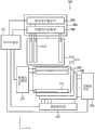
图2是示出根据本发明的触摸屏设备的示例性实施例的框图;2 is a block diagram illustrating an exemplary embodiment of a touch screen device according to the present invention;
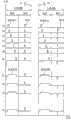
图3是示出图2中描述的触摸屏设备中的触摸驱动电压、触摸感测电压和触觉电压的示例性实施例的发送/接收时序的信号时序图;3 is a signal timing diagram illustrating transmission/reception timings of an exemplary embodiment of a touch driving voltage, a touch sensing voltage, and a haptic voltage in the touch screen device described in FIG. 2;
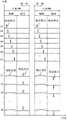
图4是示出图2中描述的触摸屏设备中的触摸驱动电压、触摸感测电压和触觉电压的替代示例性实施例的发送/接收时序的信号时序图;4 is a signal timing diagram illustrating transmission/reception timings of an alternative exemplary embodiment of a touch driving voltage, a touch sensing voltage, and a haptic voltage in the touch screen device described in FIG. 2;
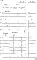
图5是示出图2中描述的触摸屏设备中的触摸驱动电压、触摸感测电压和触觉电压的另一替代示例性实施例的发送/接收时序的信号时序图;5 is a signal timing diagram illustrating transmission/reception timings of another alternative exemplary embodiment of a touch driving voltage, a touch sensing voltage, and a haptic voltage in the touch screen device described in FIG. 2;
图6是示出图2中描述的触摸屏设备中的触摸驱动电压、触摸感测电压和触觉电压的另一替代示例性实施例的发送/接收时序的信号时序图;6 is a signal timing diagram illustrating transmission/reception timings of another alternative exemplary embodiment of a touch driving voltage, a touch sensing voltage, and a haptic voltage in the touch screen device described in FIG. 2;
图7是示出图2中描述的触摸屏设备中的触摸驱动电压、触摸感测电压和触觉电压的另一替代示例性实施例的发送/接收时序的信号时序图;7 is a signal timing diagram illustrating transmission/reception timings of another alternative exemplary embodiment of a touch driving voltage, a touch sensing voltage, and a haptic voltage in the touch screen device described in FIG. 2;
图8是示出图2中描述的触摸屏设备中的触摸驱动电压、触摸感测电压和触觉电压的另一替代示例性实施例的发送/接收时序的信号时序图;8 is a signal timing diagram illustrating transmission/reception timings of another alternative exemplary embodiment of a touch driving voltage, a touch sensing voltage, and a haptic voltage in the touch screen device described in FIG. 2;
图9是示出根据本发明的触摸屏设备的替代示例性实施例的框图;9 is a block diagram illustrating an alternative exemplary embodiment of a touch screen device according to the present invention;
图10是示出图9中描述的触摸屏设备中的触摸驱动电压、触摸感测电压和触觉电压的示例性实施例的发送/接收时序的信号时序图;FIG. 10 is a signal timing diagram illustrating a transmission/reception timing of an exemplary embodiment of a touch driving voltage, a touch sensing voltage, and a haptic voltage in the touch screen device described in FIG. 9;
图11是示出图9中描述的触摸屏设备中的触摸驱动电压、触摸感测电压和触觉电压的替代示例性实施例的发送/接收时序的信号时序图;11 is a signal timing diagram illustrating transmission/reception timings of an alternative exemplary embodiment of a touch driving voltage, a touch sensing voltage, and a haptic voltage in the touch screen device described in FIG. 9;
图12是示出图9中描述的触摸屏设备中的触摸驱动电压、触摸感测电压和触觉电压的另一替代示例性实施例的发送/接收时序的信号时序图;12 is a signal timing diagram illustrating transmission/reception timings of another alternative exemplary embodiment of a touch driving voltage, a touch sensing voltage, and a haptic voltage in the touch screen device described in FIG. 9;
图13是示出图9中描述的触摸屏设备中的触摸驱动电压、触摸感测电压和触觉电压的另一替代示例性实施例的发送/接收时序的信号时序图;FIG. 13 is a signal timing diagram illustrating a transmission/reception timing of another alternative exemplary embodiment of a touch driving voltage, a touch sensing voltage, and a haptic voltage in the touch screen device described in FIG. 9;
图14是示出根据本发明的触摸屏设备的替代示例性实施例的框图;14 is a block diagram illustrating an alternative exemplary embodiment of a touch screen device according to the present invention;
图15是示出图14中描述的触摸屏设备中的触摸驱动电压、触摸感测电压和触觉电压的示例性实施例的发送/接收时序的信号时序图;FIG. 15 is a signal timing diagram illustrating a transmission/reception timing of an exemplary embodiment of a touch driving voltage, a touch sensing voltage, and a haptic voltage in the touch screen device described in FIG. 14;
图16是示出根据本发明的触摸屏设备的替代示例性实施例的框图;16 is a block diagram illustrating an alternative exemplary embodiment of a touch screen device according to the present invention;
图17是示出图16中描述的触摸屏设备中的触摸驱动电压、触摸感测电压和触觉电压的示例性实施例的发送/接收时序的信号时序图;FIG. 17 is a signal timing diagram illustrating a transmission/reception timing of an exemplary embodiment of a touch driving voltage, a touch sensing voltage, and a haptic voltage in the touch screen device described in FIG. 16;
图18是示出根据本发明的触摸屏设备的另一替代示例性实施例的框图;18 is a block diagram illustrating another alternative exemplary embodiment of a touch screen device according to the present invention;
图19是示出图18中描述的触摸屏设备中的触摸驱动电压、触摸感测电压和触觉电压的示例性实施例的发送/接收时序的信号时序图;19 is a signal timing diagram illustrating transmission/reception timing of an exemplary embodiment of a touch driving voltage, a touch sensing voltage, and a haptic voltage in the touch screen device described in FIG. 18;
图20是示出图18中描述的触摸屏设备中的触摸驱动电压、触摸感测电压和触觉电压的替代示例性实施例的发送/接收时序的信号时序图;20 is a signal timing diagram illustrating transmission/reception timings of an alternative exemplary embodiment of a touch driving voltage, a touch sensing voltage, and a haptic voltage in the touch screen device described in FIG. 18;
图21是示出图18中描述的触摸屏设备中的触摸驱动电压、触摸感测电压和触觉电压的另一替代示例性实施例的发送/接收时序的信号时序图;21 is a signal timing diagram illustrating transmission/reception timings of another alternative exemplary embodiment of a touch driving voltage, a touch sensing voltage, and a haptic voltage in the touch screen device described in FIG. 18;
图22是示出图18中描述的触摸屏设备中的触摸驱动电压、触摸感测电压和触觉电压的另一替代示例性实施例的发送/接收时序的信号时序图;FIG. 22 is a signal timing diagram illustrating a transmission/reception timing of another alternative exemplary embodiment of a touch driving voltage, a touch sensing voltage, and a haptic voltage in the touch screen device described in FIG. 18;
图23是示出图18中描述的触摸屏设备中的触摸驱动电压、触摸感测电压和触觉电压的另一替代示例性实施例的发送/接收时序的信号时序图;23 is a signal timing diagram illustrating transmission/reception timings of another alternative exemplary embodiment of a touch driving voltage, a touch sensing voltage, and a haptic voltage in the touch screen device described in FIG. 18;
图24是示出根据本发明的触摸屏设备的替代示例性实施例的框图;24 is a block diagram illustrating an alternative exemplary embodiment of a touch screen device according to the present invention;
图25是示出图24中描述的触摸屏设备中的触摸驱动电压和触觉电压的示例性实施例的发送/接收时序的信号时序图。FIG. 25 is a signal timing diagram illustrating a transmission/reception timing of an exemplary embodiment of a touch driving voltage and a haptic voltage in the touch screen device described in FIG. 24 .
具体实施方式Detailed ways
下文中,将参照附图更充分地描述本发明,在附图中示出本发明的示例性实施例。然而,本发明可以用许多不同形式来实施并且不应该被理解为限于这里阐明的实施例。相反地,提供这些实施例,使得本公开将是彻底和完全的,并且这些实施例将把本发明的范围充分地传达给本领域的技术人员。相同的参考标号始终表示相同的元件。Hereinafter, the present invention will be described more fully with reference to the accompanying drawings, in which exemplary embodiments of the invention are shown. However, this invention may be embodied in many different forms and should not be construed as limited to the embodiments set forth herein. Rather, these embodiments are provided so that this disclosure will be thorough and complete, and will fully convey the scope of the invention to those skilled in the art. The same reference numerals denote the same elements throughout.
将理解的是,当元件或层被称作“在”另一个元件或层“上”、“连接到”或“结合到”另一个元件或层时,该元件或层可以直接在另一个元件或层上、直接连接或直接结合到另一个元件或层,或者可以存在中间元件或层。相反,当元件被称作“直接在”另一个元件或层“上”、“直接连接到”或“直接结合到”另一个元件或层时,不存在中间元件或层。相同的标号始终表示相同的元件。如在这里使用的,术语“和/或”包括一个或多个相关列出项目的任意组合和所有组合。It will be understood that when an element or layer is referred to as being "on," "connected to," or "coupled to" another element or layer, it can be directly on the other element or layer. or layer, directly connected to or directly bonded to another element or layer, or intervening elements or layers may be present. In contrast, when an element is referred to as being "directly on," "directly connected to" or "directly coupled to" another element or layer, there are no intervening elements or layers present. Like reference numerals refer to like elements throughout. As used herein, the term "and/or" includes any and all combinations of one or more of the associated listed items.
将理解的是,尽管在这里可以使用术语“第一”、“第二”等来描述各种元件、组件、区域、层和/或部分,但是这些元件、组件、区域、层和/或部分不应该受这些术语的限制。这些术语只是用来将一个元件、组件、区域、层或部分与另一个元件、组件、区域、层或部分区分开来。因此,在不脱离本发明的教导的情况下,下面讨论的第一元件、组件、区域、层或部分可被命名为第二元件、组件、区域、层或部分。It will be understood that, although the terms "first", "second", etc. may be used herein to describe various elements, components, regions, layers and/or sections, these elements, components, regions, layers and/or sections Should not be limited by these terms. These terms are only used to distinguish one element, component, region, layer or section from another element, component, region, layer or section. Thus, a first element, component, region, layer or section discussed below could be termed a second element, component, region, layer or section without departing from the teachings of the present invention.
为了便于描述,在这里可以使用空间相对术语(诸如“在…下面”、“在…下方”、“下面的”、“在…上方”、“上面的”等)来描述如图中所示的一个元件或特征与其它元件或特征的关系。将理解的是,空间相对术语意在包含除了在附图中描绘的方位之外的装置在使用或操作时的不同方位。例如,如果在附图中装置被翻转,则被描述为在其它元件或特征“下方”或“下面”的元件随后将被定位为在所述其它元件或特征“上方”。因此,示例性术语“在…下方”可以包括上方和下方这两种方位。装置可被另外定位(旋转90度或者在其它方位),并相应地解释这里使用的空间相对描述符。For ease of description, spatially relative terms (such as "under", "under", "below", "above", "above", etc.) may be used herein to describe The relationship of one element or feature to other elements or features. It will be understood that the spatially relative terms are intended to encompass different orientations of the device in use or operation in addition to the orientation depicted in the figures. For example, if the device in the figures is turned over, elements described as "below" or "beneath" other elements or features would then be oriented "above" the other elements or features. Thus, the exemplary term "below" can encompass both an orientation of above and below. The device may be otherwise positioned (rotated 90 degrees or at other orientations) and the spatially relative descriptors used herein interpreted accordingly.
这里使用的术语只是为了描述特定实施例的目的,而不意图限制本发明。如这里所使用的,除非上下文另外明确指出,否则单数形式也意图包括复数形式。将进一步理解的是,当在本说明书中使用术语“包含”和/或“包括”时,说明存在所述特征、整体、步骤、操作、元件和/或组件,但不排除存在或附加一个或多个其它特征、整体、步骤、操作、元件、组件和/或它们的组合。The terminology used herein is for the purpose of describing particular embodiments only and is not intended to be limiting of the invention. As used herein, singular forms are intended to include plural forms unless the context clearly dictates otherwise. It will be further understood that when the terms "comprises" and/or "comprises" are used in this specification, it means that the features, integers, steps, operations, elements and/or components exist, but does not exclude the existence or addition of one or Various other features, integers, steps, operations, elements, components and/or combinations thereof.
除非另有定义,否则这里使用的所有术语(包括技术术语和科学术语)具有与本发明所属领域的普通技术人员所通常理解的意思相同的意思。将进一步理解的是,除非这里明确定义,否则例如在通用字典中定义的那些术语应该被解释为具有与它们在相关领域的上下文中的意思一致的意思,而将不理想地或者过于正式地解释这些术语。Unless otherwise defined, all terms (including technical and scientific terms) used herein have the same meaning as commonly understood by one of ordinary skill in the art to which this invention belongs. It will be further understood that, unless expressly defined herein, terms such as those defined in commonly used dictionaries should be construed to have a meaning consistent with their meaning in the context of the relevant field and will not be interpreted ideally or overly formally these terms.
这里参照横截面图示描述示例性实施例,这些横截面图示是理想化实施例的示意性图示。如此,将预料到由于(例如)制造技术和/或公差造成的图示形状的变化。因此,这里描述的实施例不应该被理解为限于这里示出的区域的特定形状,而是将包括由于(例如)制造所造成的形状偏差。例如,被示出或描述为平面的区域通常可具有粗糙和/或非线性的特征。此外,示出的尖锐角度可以被倒圆。因此,附图中示出的区域本质上是示意性的,它们的形状不意图示出区域的精确形状并且不意图限制这里阐明的权利要求书的范围。Exemplary embodiments are described herein with reference to cross-sectional illustrations that are schematic illustrations of idealized embodiments. As such, variations in the shapes of the illustrations due, for example, to manufacturing techniques and/or tolerances are to be expected. Thus, embodiments described herein should not be construed as limited to the particular shapes of regions illustrated herein but are to include deviations in shapes that result, for example, from manufacturing. For example, a region illustrated or described as planar may, typically, have rough and/or non-linear features. Furthermore, sharp angles shown may be rounded. Thus, the regions illustrated in the figures are schematic in nature and their shapes are not intended to illustrate the precise shape of a region and are not intended to limit the scope of the claims set forth herein.
除非这里另外指明或者上下文另外明确地否认,否则这里描述的所有方法可以按合适的次序执行。除非另外声明,否则任何和所有示例或示例性语言(例如,“诸如”)的使用只是意图更好地示出本发明,并且不对本发明的范围施加限制。说明书中的语言都不应该被理解为指示任何没有声明的元件对如这里使用的本发明的实践是必需的。All methods described herein can be performed in a suitable order unless otherwise indicated herein or otherwise clearly contradicted by context. The use of any and all examples, or exemplary language (eg, "such as"), is intended merely to better illuminate the invention and does not pose a limitation on the scope of the invention unless otherwise claimed. No language in the specification should be construed as indicating any non-claimed element as essential to the practice of the invention as used herein.
技术术语“视角”被定义为观看屏幕的观看者的视线和该视线与所观察的屏幕表面之间相交点的切线之间的角度,中心和左/右边缘视角之差被定义为并且被用于表示“视角差”。The technical term "viewing angle" is defined as the angle between the line of sight of the viewer looking at the screen and the tangent of the point of intersection between this line of sight and the screen surface being viewed, the difference between the central and left/right edge viewing angles is defined and used as Yu means "viewing angle difference".
下文中,将参照附图详细描述根据本发明的用于呈现触觉图像的方法的示例性实施例和用于执行该方法的触摸屏设备的示例性实施例。Hereinafter, an exemplary embodiment of a method for presenting a tactile image and an exemplary embodiment of a touch screen device for performing the method according to the present invention will be described in detail with reference to the accompanying drawings.
图1是示出根据本发明的触觉图像呈现方法的示例性实施例的流程图。FIG. 1 is a flowchart illustrating an exemplary embodiment of a tactile image presentation method according to the present invention.
参照图1,在显示面板上显示图像(步骤S110)。在显示面板上显示的图像可以具有各种纹理。在一个示例性实施例中,例如,图像可以是不平坦纹理的图像,诸如树皮或岩石表面。在这种实施例中,例如,图像可以是金属纹理的图像或织物纹理的图像。Referring to FIG. 1 , an image is displayed on a display panel (step S110 ). Images displayed on the display panel may have various textures. In one exemplary embodiment, for example, the image may be an image of an uneven texture, such as tree bark or a rock surface. In such an embodiment, the image may be, for example, an image of a metal texture or an image of a fabric texture.
在显示面板上不显示图像的显示垂直消隐间隔(vertical blanking interval)中,向在布置在显示面板上的触觉触摸面板上设置的触摸驱动线提供触摸驱动电压(步骤S120),并且通过设置在触觉触摸面板上的触摸感测线接收触摸感测电压(步骤S130)。在示例性实施例中,触摸驱动线和触摸感测线可以设置在同一基板上。在替代示例性实施例中,触摸驱动线和触摸感测线可以分别设置在不同基板上。在触摸驱动线和触摸感测线设置在彼此不同的基板上的这种实施例中,其上具有触摸感测线的基板被设置在其上具有触摸驱动线的基板上。In the display vertical blanking interval (vertical blanking interval) when no image is displayed on the display panel, the touch driving voltage is supplied to the touch driving line provided on the tactile touch panel arranged on the display panel (step S120), and by setting the A touch sensing line on the tactile touch panel receives a touch sensing voltage (step S130 ). In exemplary embodiments, touch driving lines and touch sensing lines may be disposed on the same substrate. In alternative exemplary embodiments, touch driving lines and touch sensing lines may be disposed on different substrates, respectively. In such embodiments where the touch drive lines and the touch sense lines are disposed on different substrates from each other, the substrate having the touch sense lines thereon is disposed on the substrate having the touch drive lines thereon.
当触摸驱动电压(例如,驱动电压或驱动电流)被施加到触摸驱动线时,在与相应触摸驱动线相邻的触摸感测线的外围部分形成电容器。例如,当触摸工具(诸如用户的手指或触摸笔)接近电容器时,从电容器产生电荷,使得电场的强度发生变化。通过触摸感测线基于电场的变化量来收集触摸感测电压。When a touch driving voltage (for example, a driving voltage or a driving current) is applied to a touch driving line, a capacitor is formed at a peripheral portion of a touch sensing line adjacent to the corresponding touch driving line. For example, when a touch implement such as a user's finger or a touch pen approaches the capacitor, charges are generated from the capacitor so that the strength of the electric field changes. The touch sensing voltage is collected through the touch sensing line based on the variation amount of the electric field.
然后,确定是否发生了触摸(步骤S140)。在一个示例性实施例中,例如,当收集到的触摸感测电压大于或等于参考电压时,可以确定在相应部分发生了触摸。Then, it is determined whether a touch has occurred (step S140). In one exemplary embodiment, for example, when the collected touch sensing voltage is greater than or equal to a reference voltage, it may be determined that a touch has occurred at a corresponding portion.
当在步骤S140中确定没有产生触摸时,确定触觉图像呈现方法是否结束(步骤S142)。当在步骤S142中确定触觉图像呈现方法结束时,终止触觉图像呈现方法,而当触觉图像呈现方法未结束时,反馈回步骤S110。When it is determined in step S140 that no touch is generated, it is determined whether the haptic image presentation method ends (step S142 ). When it is determined in step S142 that the tactile image presentation method is finished, the tactile image presentation method is terminated, and when the tactile image presentation method is not finished, it is fed back to step S110 .
在步骤S140中,当确定发生了触摸时,基于收集到的感测电压来确定触摸位置(步骤S150)。In step S140, when it is determined that a touch has occurred, a touch position is determined based on the collected sensing voltage (step S150).
然后,向触摸产生部分的触摸电极提供与显示的图像相应的触觉电压(步骤S160),然后反馈回步骤S110。可以将触觉电压以具有各种宽度和各种幅值的脉冲形式施加到触摸电极。在一个示例性实施例中,例如,当不平坦纹理的量较大时,可以向触摸电极施加大幅值的触觉电压,而当不平坦纹理的量较小时,可以向触摸电极施加小幅值的触觉电压。在这种实施例中,可以按各种时序向触摸电极施加触觉电压。在一个示例性实施例中,例如,在与向触摸电极施加触摸驱动电压的触摸间隔不同的触觉间隔中,可以按相同时序或者按不同时序向触摸电极施加触觉电压。在这种实施例中,在向触摸电极施加触摸驱动电压的触摸间隔中,可以按与当不向触摸电极施加触摸驱动电压时不同的时序向触摸电极施加触觉电压。在示例性实施例中,可以按连续时序向触摸电极施加触觉电压。将参照附图更详细地描述连续时序。Then, a tactile voltage corresponding to the displayed image is supplied to the touch electrode of the touch generating part (step S160 ), and then fed back to step S110 . The tactile voltage may be applied to the touch electrodes in the form of pulses having various widths and various amplitudes. In an exemplary embodiment, for example, when the amount of the uneven texture is large, a tactile voltage of a large magnitude may be applied to the touch electrodes, and when the amount of the uneven texture is small, a haptic voltage of a small magnitude may be applied to the touch electrodes. tactile voltage. In such an embodiment, haptic voltages may be applied to the touch electrodes at various timings. In one exemplary embodiment, for example, in a touch interval different from a touch interval in which a touch driving voltage is applied to the touch electrodes, the haptic voltage may be applied to the touch electrodes at the same timing or at a different timing. In such an embodiment, in the touch interval in which the touch driving voltage is applied to the touch electrodes, the haptic voltage may be applied to the touch electrodes at a different timing than when the touch driving voltage is not applied to the touch electrodes. In an exemplary embodiment, the tactile voltage may be applied to the touch electrodes in continuous timing. The sequential timing will be described in more detail with reference to the accompanying drawings.
如上所述,在示例性实施例中,在不施加触摸驱动电压的消隐间隔中,向触觉触摸面板施加与图像相应的触觉电压,从而有效防止由触觉图像产生的电场阻止触摸操作。As described above, in an exemplary embodiment, a haptic voltage corresponding to an image is applied to the haptic touch panel during a blanking interval in which no touch driving voltage is applied, thereby effectively preventing an electric field generated by a haptic image from blocking a touch operation.
下文中,将描述用于执行触觉图像呈现方法的触摸屏设备的示例性实施例。Hereinafter, an exemplary embodiment of a touch screen device for performing a tactile image presentation method will be described.
图2是示出根据本发明的触摸屏设备的示例性实施例的框图。FIG. 2 is a block diagram illustrating an exemplary embodiment of a touch screen device according to the present invention.
参照图2,根据本发明的触摸屏设备100的示例性实施例包括触觉触摸面板110、电压发送/接收部120、显示面板130、数据驱动部140、扫描驱动部150和时序控制部160。Referring to FIG. 2 , an exemplary embodiment of a
触觉触摸面板110包括多个触摸驱动线112和多个触摸感测线114,其中,触摸驱动线112和触摸感测线114执行触摸功能和触感反馈功能。触摸驱动线112可以基本上平行于Y轴延伸并且可以沿X轴布置。触摸感测线114可以基本上平行于X轴延伸并且可以沿Y轴布置。The
在示例性实施例中,触摸驱动线112具有矩形形状的铟锡氧化物(“ITO”)图案以链状彼此连接的结构。在这种实施例中,触摸感测线114具有矩形形状的ITO图案以链状彼此连接的结构。因此,当在XY平面上观察时,触觉触摸面板110可以具有矩阵形状。在示例性实施例中,如图2中所示,触摸驱动线112和触摸感测线114被设置成彼此交叉,并且还在触摸驱动线112和触摸感测线114的交叉区域上设置绝缘层(未示出)。In an exemplary embodiment, the
电压发送/接收部120包括触摸电压施加部122、感测电压收集部124和触觉电压施加部126,其中,触摸电压施加部122、感测电压收集部124和触觉电压施加部126中的每个连接到触觉触摸面板110和时序控制部160。The voltage transmitting/receiving
触摸电压施加部122连接到触摸驱动线112,并且向触摸驱动线112施加触摸驱动电压。The touch
感测电压收集部124连接到触摸感测线114,并且接收触摸感测电压。感测电压收集部124向时序控制部160提供接收到的触摸感测电压。The sensing
触觉电压施加部126连接到触摸驱动线112和触摸感测线114。在不向触摸驱动线112施加触摸驱动电压的消隐间隔中,触觉电压施加部126向触摸驱动线112和触摸感测线114施加与在显示面板130上显示的图像对应的触觉电压。在示例性实施例中,消隐间隔可以在图像的垂直消隐间隔中。在示例性实施例中,触觉电压大于触摸驱动电压。在一个示例性实施例中,例如,当在显示面板130上显示的图像是具有不平坦纹理的图像时,触觉电压施加部126向触摸驱动线112和触摸感测线114提供具有第一电平的触觉电压。可以按交替方式施加触觉电压,以增强触感反馈效果。在一个示例性实施例中,例如,可以在第一消隐间隔中向触摸驱动线112和触摸感测线114施加具有第一相位的第一触觉电压,并且可以在第二消隐间隔中向触摸驱动线112和触摸感测线114施加具有与第一相位相反的第二相位的第二触觉电压。The tactile
触觉电压施加部126和触摸电压施加部122在不同时间操作。触觉电压施加部126和触摸电压施加部122可以基于时序控制部160的控制来操作。The haptic
在触觉触摸面板110下方设置显示面板130。例如,显示面板130可以是液晶显示面板、等离子体显示面板或有机发光显示面板。在显示面板130是液晶显示面板的示例性实施例中,显示面板130可以包括用于显示图像的多个像素电极(未示出)、用于激活像素电极的多个开关元件(未示出)。在这种实施例中,开关元件可以包括薄膜晶体管(“TFT”)。The
数据驱动部140向设置在显示面板130上的像素电极提供数据信号。在一个示例性实施例中,例如,当显示面板130包括开关元件时,数据驱动部140通过开关元件向像素电极提供数据信号。The
扫描驱动部150输出用于激活在显示面板130上设置的开关元件的扫描信号。当扫描信号被施加到开关元件时,开关元件被接通,以将数据信号传送到像素电极。在这种实施例中,在不向显示面板130施加扫描信号的垂直消隐间隔中,触觉电压施加部126向触摸驱动线112和触摸感测线114中的每个施加触觉电压。The
时序控制部160向数据驱动部150提供用于在显示面板130上显示图像的图像数据和与图像数据对应的第一控制信号,并且向扫描驱动部150提供用于激活在显示面板130上设置的开关元件的第二控制信号。在这种实施例中,时序控制部160向触摸电压施加部122提供用于执行触摸功能的第三控制信号,并且接收从感测电压收集部124提供的触摸感测电压。在这种实施例中,时序控制部160向触觉电压施加部126提供用于执行触感反馈功能的第四控制信号。The
在示例性实施例中,如图2中所示,触摸屏设备100还可以包括屏蔽层170。屏蔽层170被设置在触觉触摸面板110和显示面板130之间,并且有效防止从触觉电压施加部126输出的触觉电压被施加到显示面板130。In an exemplary embodiment, as shown in FIG. 2 , the
在替代示例性实施例中,屏蔽层170可以被设置在显示面板130内。在显示面板130是包括阵列基板、与阵列基板相对的对向基板和置于阵列基板与对向基板之间的液晶层的液晶显示面板的示例性实施例中,屏蔽层170可以被设置在对向基板上。在替代示例性实施例中,屏蔽层170可以被设置在阵列基板上。In an alternative exemplary embodiment, the
下文中,将描述向在图2中描述的触觉触摸面板110施加的触摸驱动电压和触觉电压的各种示例性实施例的时序。在后面的信号时序图中,D1、D2、D3、…、Dn表示触摸驱动线,并且S1、S2、S3、…、Sn表示触摸感测线,其中,n是自然数。Hereinafter, timings of various exemplary embodiments of touch driving voltages and haptic voltages applied to the
图3是示出图2中描述的触摸屏设备中的触摸驱动电压、触摸感测电压和触觉电压的示例性实施例的发送/接收时序的信号时序图。FIG. 3 is a signal timing diagram illustrating a transmission/reception timing of an exemplary embodiment of a touch driving voltage, a touch sensing voltage, and a haptic voltage in the touch screen device described in FIG. 2 .
参照图2和图3,帧(例如第一帧和第二帧)中的每个包括有在显示面板上不显示图像的垂直消隐间隔(V_BLANK),并且垂直消隐间隔包括触摸间隔(TOUCH)和触觉间隔(TACTILE)。Referring to FIGS. 2 and 3 , each of the frames (for example, the first frame and the second frame) includes a vertical blanking interval (V_BLANK) in which no image is displayed on the display panel, and the vertical blanking interval includes a touch interval (TOUCH ) and tactile interval (TACTILE).
在触摸间隔中,从触摸电压施加部122输出触摸驱动电压并且向触摸驱动线D1、D2、D3、…、Dn中的每个顺序地施加触摸驱动电压,并且由感测电压收集部124收集与触摸感测线S1、S2、S3、…、Sn对应的触摸感测电压。In the touch interval, the touch driving voltage is output from the touch
在触觉间隔中,向触摸驱动线D1、D2、D3、…、Dn施加触觉电压时的时序与向触摸感测线S1、S2、S3、…、Sn施加触觉电压时的时序基本上相同。在示例性实施例中,在触觉间隔内的预定时间期间,向触摸驱动线D1、D2、D3、…、Dn和触摸感测线S1、S2、S3、…、Sn施加触觉电压。在一个示例性实施例中,例如,向第一触摸驱动线施加触觉电压的施加时间与向第二触摸驱动线施加触觉电压的施加时间基本上相同。在这种实施例中,向第一触摸感测线施加触觉电压的施加时间与向第二触摸感测线施加触觉电压的施加时间基本上相同。In the haptic interval, the timing of applying haptic voltages to the touch driving lines D1 , D2 , D3 , . In an exemplary embodiment, a haptic voltage is applied to the touch driving lines D1 , D2 , D3 , . . . , Dn and the touch sensing lines S1 , S2 , S3 , . In one exemplary embodiment, for example, the application time of applying the haptic voltage to the first touch driving line is substantially the same as the application time of applying the haptic voltage to the second touch driving line. In such an embodiment, the application time of the haptic voltage to the first touch-sensing line is substantially the same as the application time of the haptic voltage to the second touch-sensing line.
触觉电压的相位按每帧反转。在一个示例性实施例中,例如,在与第一垂直消隐间隔对应的触觉间隔中,向触摸驱动线D1、D2、D3、…、Dn和触摸感测线S1、S2、S3、…、Sn施加第一触觉电压。在与第二垂直消隐间隔对应的触觉间隔中,向触摸驱动线D1、D2、D3、…、Dn和触摸感测线S1、S2、S3、…、Sn施加相位与第一触觉电压相反的第二触觉电压。因此,触觉电压的相位按每帧反转,使得触感反馈效果(例如,振动效果)显著增加。The phase of the haptic voltage is reversed every frame. In an exemplary embodiment, for example, in the tactile interval corresponding to the first vertical blanking interval, the touch driving lines D1, D2, D3, ..., Dn and the touch sensing lines S1, S2, S3, ..., Sn applies a first tactile voltage. In the tactile interval corresponding to the second vertical blanking interval, a tactile voltage whose phase is opposite to that of the first tactile voltage is applied to the touch driving lines D1, D2, D3, ..., Dn and the touch sensing lines S1, S2, S3, ..., Sn. Second tactile voltage. Therefore, the phase of the haptic voltage is reversed every frame, so that the haptic feedback effect (eg, vibration effect) is significantly increased.
在示例性实施例中,如图3中所示,向所有触摸驱动线D1、D2、D3、…、Dn和所有触摸感测线S1、S2、S3、…、Sn同时施加触觉电压。在替代示例性实施例中,可以基于发生触摸的区域来施加触觉电压。In an exemplary embodiment, as shown in FIG. 3 , haptic voltages are simultaneously applied to all touch driving lines D1 , D2 , D3 , . . . , Dn and all touch sensing lines S1 , S2 , S3 , . . . , Sn. In an alternative exemplary embodiment, the haptic voltage may be applied based on the area where the touch occurs.
在一个示例性实施例中,例如,当感测电压收集部124收集到触摸感测电压时,时序控制部160可以确定在某个位置发生了触摸。在这种实施例中,时序控制部160向触觉电压施加部126提供触摸的信息。触觉电压施加部126向与触摸位置对应的部分中的触摸驱动线和与触摸位置对应的部分中的触摸感测线施加触觉电压。在这种实施例中,与触摸位置对应的部分中的触摸驱动线的数量可以大于2。在这种实施例中,与触摸位置对应的部分中的触摸感测线的数量可以大于2。In an exemplary embodiment, for example, when the sensing
如上所述,在示例性实施例中,在显示面板上不显示图像的垂直消隐间隔的触摸间隔期间,向触摸驱动线施加触摸驱动电压,并且收集触摸感测电压,而在触觉间隔中,向触摸驱动线和触摸感测线同时施加触觉电压,使得可以在显示在显示面板上的图像中执行触感反馈功能。As described above, in the exemplary embodiment, during the touch interval of the vertical blanking interval in which no image is displayed on the display panel, the touch driving voltage is applied to the touch driving line and the touch sensing voltage is collected, while in the touch interval, Simultaneously applying a tactile voltage to the touch driving line and the touch sensing line makes it possible to perform a tactile feedback function in an image displayed on the display panel.
图4是示出图2中描述的触摸屏设备中的触摸驱动电压、触摸感测电压和触觉电压的替代示例性实施例的发送/接收时序的信号时序图。在图4中,向触摸驱动线D1、D2、D3、…、Dn施加的触觉电压的幅值大于向触摸驱动线D1、D2、D3、…、Dn施加的触摸驱动电压的幅值。在图4中,向触摸感测线S1、S2、S3、…、Sn施加的触摸感测电压的幅值小于向触摸感测线S1、S2、S3、…、Sn施加的触觉电压的幅值。FIG. 4 is a signal timing diagram illustrating a transmission/reception timing of an alternative exemplary embodiment of a touch driving voltage, a touch sensing voltage, and a haptic voltage in the touch screen device described in FIG. 2 . In FIG. 4 , the amplitudes of the tactile voltages applied to the touch driving lines D1 , D2 , D3 , . In FIG. 4, the magnitude of the touch sensing voltage applied to the touch sensing lines S1, S2, S3, ..., Sn is smaller than the magnitude of the tactile voltage applied to the touch sensing lines S1, S2, S3, ..., Sn. .
参照图2和图4,在显示面板上不显示图像的垂直消隐间隔包括触摸间隔和触觉间隔。触觉间隔包括第一触觉帧间隔和第二触觉帧间隔。Referring to FIGS. 2 and 4 , the vertical blanking interval in which an image is not displayed on the display panel includes a touch interval and a tactile interval. The haptic intervals include a first haptic frame interval and a second haptic frame interval.
在触摸间隔中,从触摸电压施加部122输出触摸驱动电压并且分别向触摸驱动线D1、D2、D3、…、Dn顺序地施加触摸驱动电压,并且由感测电压收集部124收集触摸感测线S1、S2、S3、…、Sn的触摸感测电压。在示例性实施例中,在向触摸驱动线D1、D2、D3、…、Dn施加所有触摸驱动电压的时间期间,感测电压收集部124向触摸感测线S1、S2、S3、…、Sn施加预定电平的电压,以收集触摸感测电压。在一个示例性实施例中,例如,当通过第一触摸感测线S1收集的第一感测电压大于或等于预定电平时,可以确定在第一触摸感测线S1上发生了触摸。In the touch interval, the touch driving voltage is output from the touch
在第一触觉帧间隔中,以相同时序向触摸驱动线D1、D2、D3、…、Dn和触摸感测线S1、S2、S3、…、Sn中的每个施加第一触觉电压。In the first haptic frame interval, the first haptic voltage is applied to each of the touch driving lines D1 , D2 , D3 , . . . , Dn and the touch sensing lines S1 , S2 , S3 , .
在第二触觉帧间隔中,以相同时序向触摸驱动线D1、D2、D3、…、Dn和触摸感测线S1、S2、S3、…、Sn中的每个施加相位与第一触觉电压相反的第二触觉电压。In the second haptic frame interval, each of the touch driving lines D1, D2, D3, . . . , Dn and the touch sensing lines S1, S2, S3, . of the second tactile voltage.
如上所述,在示例性实施例中,在垂直消隐间隔的第一触觉帧间隔中,以相同时序向触摸驱动线和触摸感测线施加第一触觉电压,并且在垂直消隐间隔的第二触觉帧间隔中,以相同时序向触摸驱动线和触摸感测线施加相位与第一触觉电压相反的第二触觉电压,从而针对在显示面板上显示的图像执行触感反馈功能。As described above, in an exemplary embodiment, in the first haptic frame interval of the vertical blanking interval, the first haptic voltage is applied to the touch driving line and the touch sensing line at the same timing, and in the first haptic frame interval of the vertical blanking interval In two haptic frame intervals, a second haptic voltage with a phase opposite to the first haptic voltage is applied to the touch driving line and the touch sensing line at the same timing, so as to perform a haptic feedback function on an image displayed on the display panel.
图5是示出图2中描述的触摸屏设备中的触摸驱动电压、触摸感测电压和触觉电压的另一替代示例性实施例的发送/接收时序的信号时序图。如图5中所示,在示例性实施例中,向触摸驱动线D1、D2、D3、…、Dn施加的触觉电压的幅值大于向触摸驱动线D1、D2、D3、…、Dn施加的触摸驱动电压的幅值。在这种实施例中,向触摸感测线S1、S2、S3、…、Sn施加的触摸感测电压的幅值小于向触摸感测线S1、S2、S3、…、Sn施加的触觉电压的幅值。FIG. 5 is a signal timing diagram illustrating a transmission/reception timing of another alternative exemplary embodiment of a touch driving voltage, a touch sensing voltage, and a haptic voltage in the touch screen device described in FIG. 2 . As shown in FIG. 5, in an exemplary embodiment, the amplitude of the haptic voltage applied to the touch driving lines D1, D2, D3, ..., Dn is larger than that applied to the touch driving lines D1, D2, D3, ..., Dn. The magnitude of the touch drive voltage. In such an embodiment, the magnitude of the touch sensing voltage applied to the touch sensing lines S1, S2, S3, . . . amplitude.
参照图2和图5,触摸帧间隔包括第一触觉帧间隔和第二触觉帧间隔。Referring to FIGS. 2 and 5 , the touch frame interval includes a first haptic frame interval and a second haptic frame interval.
在触摸帧间隔中,从触摸电压施加部122输出触摸驱动电压并且向触摸驱动线D1、D2、D3、…、Dn中的每个顺序地施加触摸驱动电压,并且由感测电压收集部124收集与触摸感测线S1、S2、S3、…、Sn对应的触摸感测电压。在示例性实施例中,在施加触摸驱动电压的时间,感测电压收集部124向触摸感测线S1、S2、S3、…、Sn施加预定电平的电压,以收集触摸感测电压。在一个示例性实施例中,例如,按照向触摸驱动线D1、D2、D3、…、Dn和触摸感测线S1、S2、S3、…、Sn施加触摸驱动电压的时间,向所有触摸感测线S1、S2、S3、…、Sn连续地施加预定电平的电压。因此,当通过第一触摸感测线S1收集的第一感测电压大于或等于预定电平的电压时,可以确定在第一触摸感测线S1上发生了触摸。In the touch frame interval, the touch driving voltage is output from the touch
在第一触觉帧间隔中,在施加触摸驱动电压之后,向触摸驱动线D1、D2、D3、…、Dn和触摸感测线S1、S2、S3、…、Sn顺序地施加第一触觉电压。向触摸驱动线D1、D2、D3、…、Dn和触摸感测线S1、S2、S3、…、Sn施加第一触觉电压的时间与施加触摸驱动电压的时间或者施加触摸感测电压的时间不重叠。In the first haptic frame interval, after the touch driving voltage is applied, the first haptic voltage is sequentially applied to the touch driving lines D1 , D2 , D3 , . . . , Dn and the touch sensing lines S1 , S2 , S3 , . The time when the first tactile voltage is applied to the touch driving lines D1, D2, D3, . . . , Dn and the touch sensing lines S1, S2, S3, . overlapping.
在第二触觉帧间隔中,在施加触摸驱动电压之前,向触摸驱动线D1、D2、D3、…、Dn和触摸感测线S1、S2、S3、…、Sn顺序地施加相位与第一触觉电压相反的第二触觉电压。向触摸驱动线D1、D2、D3、…、Dn和触摸感测线S1、S2、S3、…、Sn施加第二触觉电压的时间与向触摸驱动线D1、D2、D3、…、Dn施加触摸驱动电压的时间或者向触摸感测线S1、S2、S3、…、Sn施加触摸感测电压的时间不重叠。In the second haptic frame interval, before applying the touch driving voltage, the phase and the first haptic are sequentially applied to the touch driving lines D1, D2, D3, ..., Dn and the touch sensing lines S1, S2, S3, ..., Sn. A second tactile voltage of opposite voltage. The time for applying the second tactile voltage to the touch driving lines D1, D2, D3, . . . , Dn and the touch sensing lines S1, S2, S3, . The time of driving the voltage or the time of applying the touch sensing voltage to the touch sensing lines S1 , S2 , S3 , . . . , Sn does not overlap.
在示例性实施例中,如图5中所示,向所有触摸驱动线D1、D2、D3、…、Dn和所有触摸感测线S1、S2、S3、…、Sn同时施加触觉电压。在替代示例性实施例中,可以根据发生触摸的区域局部地施加触觉电压。In an exemplary embodiment, as shown in FIG. 5 , haptic voltages are simultaneously applied to all touch driving lines D1 , D2 , D3 , . . . , Dn and all touch sensing lines S1 , S2 , S3 , . . . , Sn. In an alternative exemplary embodiment, the haptic voltage may be applied locally according to the area where the touch occurs.
在一个示例性实施例中,例如,当感测电压收集部124收集到触摸感测电压时,时序控制部160可以确定在某个位置发生了触摸。在这种实施例中,时序控制部160向触觉电压施加部126提供触摸位置的信息。触觉电压施加部126向与触摸位置对应的部分中的触摸驱动线和与触摸位置对应的部分中的触摸感测线施加触觉电压。在这种实施例中,与触摸位置对应的部分中的触摸驱动线的数量可以大于2。在这种实施例中,与触摸位置对应的部分中的触摸感测线的数量可以大于2。In an exemplary embodiment, for example, when the sensing
如上所述,在示例性实施例中,在向触摸驱动线施加触摸驱动电压的触摸帧间隔中的第一触觉帧间隔中,向触摸驱动线和触摸感测线施加第一触觉电压,并且在触摸帧间隔中的第二触觉帧间隔中,向触摸驱动线和触摸感测线施加相位与第一触觉电压相反的第二触觉电压,从而针对在显示面板上显示的图像执行触感反馈功能。As described above, in an exemplary embodiment, in the first haptic frame interval in the touch frame interval in which the touch driving voltage is applied to the touch driving line, the first tactile voltage is applied to the touch driving line and the touch sensing line, and In a second haptic frame interval of the touch frame intervals, a second haptic voltage having a phase opposite to that of the first haptic voltage is applied to the touch driving lines and the touch sensing lines, thereby performing a haptic feedback function for an image displayed on the display panel.
图6是示出图2中描述的触摸屏设备中的触摸驱动电压、触摸感测电压和触觉电压的另一替代示例性实施例的发送/接收时序的信号时序图。在示例性实施例中,如图6中所示,向触摸驱动线D1、D2、D3、…、Dn施加的触觉电压的幅值大于向触摸驱动线D1、D2、D3、…、Dn施加的触摸驱动电压的幅值。在这种实施例中,向触摸感测线S1、S2、S3、…、Sn施加的触摸感测电压的幅值小于向触摸感测线S1、S2、S3、…、Sn施加的触觉电压的幅值。FIG. 6 is a signal timing diagram illustrating a transmission/reception timing of another alternative exemplary embodiment of a touch driving voltage, a touch sensing voltage, and a haptic voltage in the touch screen device described in FIG. 2 . In an exemplary embodiment, as shown in FIG. 6, the amplitude of the haptic voltage applied to the touch driving lines D1, D2, D3, ..., Dn is larger than that applied to the touch driving lines D1, D2, D3, ..., Dn. The magnitude of the touch drive voltage. In such an embodiment, the magnitude of the touch sensing voltage applied to the touch sensing lines S1, S2, S3, . . . amplitude.
参照图2和图6,在显示面板上不显示图像的奇数垂直消隐间隔中(例如在第二帧的垂直消隐间隔中),从触摸电压施加部122输出触摸驱动电压并且向触摸驱动线D1、D2、D3、…、Dn中的每个顺序地施加触摸驱动电压,并且由感测电压收集部124收集与触摸感测线S1、S2、S3、…、Sn对应的触摸感测电压。在这种实施例中,在不向触摸驱动线D1、D2、D3、…、Dn施加触摸驱动电压并且不收集触摸感测电压的时间中,向触摸驱动线D1、D2、D3、…、Dn中的每个和触摸感测线S1、S2、S3、…、Sn中的每个顺序地施加第一触觉电压。Referring to FIGS. 2 and 6 , in an odd vertical blanking interval in which no image is displayed on the display panel (for example, in a vertical blanking interval of a second frame), a touch driving voltage is output from the touch
在偶数垂直消隐间隔中(例如在第一帧的垂直消隐间隔中),从触摸电压施加部122输出触摸驱动电压并且向触摸驱动线D1、D2、D3、…、Dn中的每个顺序地施加触摸驱动电压,并且由感测电压收集部124收集与触摸感测线S1、S2、S3、…、Sn对应的触摸感测电压。在这种实施例中,在不向触摸驱动线D1、D2、D3、…、Dn施加触摸驱动电压并且不收集触摸感测电压的时间期间,向触摸驱动线D1、D2、D3、…、Dn和触摸感测线S1、S2、S3、…、Sn顺序地施加相位与第一触觉电压相反的第二触觉电压。In an even-numbered vertical blanking interval (for example, in the vertical blanking interval of the first frame), the touch driving voltage is output from the touch
在示例性实施例中,如图6中所示,在向触摸驱动线D1、D2、D3、…、Dn施加触摸驱动电压的时间期间,感测电压收集部124向触摸感测线S1、S2、S3、…、Sn施加预定电平的电压。在一个示例性实施例中,例如,在向触摸驱动线D1、D2、D3、…、Dn施加触摸驱动电压的时间期间,向所有触摸感测线S1、S2、S3、…、Sn连续地施加预定电平的电压。因此,当通过第一触摸感测线S1收集的第一感测电压大于或等于预定电平的电压时,可以确定在第一触摸感测线S1上发生了触摸。In an exemplary embodiment, as shown in FIG. 6 , during the time when the touch driving voltage is applied to the touch driving lines D1 , D2 , D3 , . , S3, . . . , Sn apply a voltage of a predetermined level. In one exemplary embodiment, for example, during the time when the touch drive voltage is applied to the touch drive lines D1 , D2 , D3 , . predetermined level of voltage. Accordingly, when the first sensing voltage collected through the first touch sensing line S1 is greater than or equal to a predetermined level of voltage, it may be determined that a touch has occurred on the first touch sensing line S1.
如图6中所示,向所有触摸驱动线D1、D2、D3、…、Dn和所有触摸感测线S1、S2、S3、…、Sn顺序地施加触觉电压。在替代示例性实施例中,可以根据发生触摸的区域局部地施加触觉电压。As shown in FIG. 6 , haptic voltages are sequentially applied to all touch driving lines D1 , D2 , D3 , . . . , Dn and all touch sensing lines S1 , S2 , S3 , . . . , Sn. In an alternative exemplary embodiment, the haptic voltage may be applied locally according to the area where the touch occurs.
如上所述,在示例性实施例中,在显示面板上不显示图像的奇数垂直消隐间隔中,向其顺序地施加第一触觉电压,并且在显示面板上不显示图像的偶数垂直消隐间隔中,向其顺序地施加相位与第一触觉电压相反的第二触觉电压,从而针对在显示面板上显示的图像执行触感反馈功能。As described above, in an exemplary embodiment, the first haptic voltage is sequentially applied thereto in odd-numbered vertical blanking intervals in which no image is displayed on the display panel, and in even-numbered vertical blanking intervals in which no image is displayed on the display panel. , a second haptic voltage having a phase opposite to that of the first haptic voltage is sequentially applied thereto, thereby performing a haptic feedback function on an image displayed on the display panel.
图7是示出图2中描述的触摸屏设备中的触摸驱动电压、触摸感测电压和触觉电压的另一替代示例性实施例的发送/接收时序的信号时序图。如图7中所示,在示例性实施例中,向触摸驱动线D1、D2、D3、…、Dn施加的触觉电压的幅值大于向触摸驱动线D1、D2、D3、…、Dn施加的触摸驱动电压的幅值。在这种实施例中,向触摸感测线S1、S2、S3、…、Sn施加的触摸感测电压的幅值小于向触摸感测线S1、S2、S3、…、Sn施加的触觉电压的幅值。FIG. 7 is a signal timing diagram illustrating a transmission/reception timing of another alternative exemplary embodiment of a touch driving voltage, a touch sensing voltage, and a haptic voltage in the touch screen device described in FIG. 2 . As shown in FIG. 7, in an exemplary embodiment, the amplitude of the haptic voltage applied to the touch driving lines D1, D2, D3, ..., Dn is larger than that applied to the touch driving lines D1, D2, D3, ..., Dn. The magnitude of the touch drive voltage. In such an embodiment, the magnitude of the touch sensing voltage applied to the touch sensing lines S1, S2, S3, . . . amplitude.
参照图2和图7,两个触摸帧间隔(即,第一触摸帧间隔和第二触摸帧间隔)可以对应于一个触觉帧间隔。在第一触摸帧间隔中向触摸驱动线D1、D2、D3、…、Dn施加触摸驱动电压之前,向触摸驱动线D1、D2、D3、…、Dn施加触觉电压,并且在第二触摸帧间隔中向触摸驱动线D1、D2、D3、…、Dn施加触摸驱动电压之后,向触摸驱动线D1、D2、D3、…、Dn施加触觉电压。Referring to FIGS. 2 and 7 , two touch frame intervals (ie, a first touch frame interval and a second touch frame interval) may correspond to one haptic frame interval. Before the touch drive voltage is applied to the touch drive lines D1, D2, D3, ..., Dn in the first touch frame interval, the tactile voltage is applied to the touch drive lines D1, D2, D3, ..., Dn, and in the second touch frame interval After the touch driving voltage is applied to the touch driving lines D1 , D2 , D3 , . . . , Dn, the tactile voltage is applied to the touch driving lines D1 , D2 , D3 , .
在第一触摸帧间隔中,从触摸电压施加部122输出触摸驱动电压并且向触摸驱动线D1、D2、D3、…、Dn中的每个顺序地施加触摸驱动电压,并且由感测电压收集部124收集与触摸感测线S1、S2、S3、…、Sn对应的触摸感测电压。在这种实施例中,在向触摸驱动线D1、D2、D3、…、Dn施加触摸驱动电压之前,向触摸驱动线D1、D2、D3、…、Dn和触摸感测线S1、S2、S3、…、Sn施加触觉电压。In the first touch frame interval, the touch driving voltage is output from the touch
在第二触摸帧间隔中,从触摸电压施加部122输出触摸驱动电压并且向触摸驱动线D1、D2、D3、…、Dn中的每个顺序地施加触摸驱动电压,并且由感测电压收集部124收集与触摸感测线S1、S2、S3、…、Sn对应的触摸感测电压。在这种实施例中,在向触摸驱动线D1、D2、D3、…、Dn施加触摸驱动电压之后,向触摸驱动线D1、D2、D3、…、Dn和触摸感测线S1、S2、S3、…、Sn施加触觉电压。In the second touch frame interval, the touch driving voltage is output from the touch
在示例性实施例中,如图7中所示,在向触摸驱动线D1、D2、D3、…、Dn施加触摸驱动电压的时间期间,感测电压收集部124向触摸感测线S1、S2、S3、…、Sn施加预定电平的电压,以收集触摸感测电压。在一个示例性实施例中,例如,在向触摸驱动线D1、D2、D3、…、Dn施加触摸驱动电压的时间期间,向所有触摸感测线S1、S2、S3、…、Sn连续地施加预定电平的电压。因此,当通过第一触摸感测线S1收集的第一感测电压大于或等于预定电平的电压时,可以确定在第一触摸感测线S1上发生了触摸。In an exemplary embodiment, as shown in FIG. 7 , during the time when the touch driving voltage is applied to the touch driving lines D1 , D2 , D3 , . , S3 , . . . , Sn apply a predetermined level of voltage to collect a touch sensing voltage. In one exemplary embodiment, for example, during the time when the touch drive voltage is applied to the touch drive lines D1 , D2 , D3 , . predetermined level of voltage. Accordingly, when the first sensing voltage collected through the first touch sensing line S1 is greater than or equal to a predetermined level of voltage, it may be determined that a touch has occurred on the first touch sensing line S1.
如图7中所示,向所有触摸驱动线D1、D2、D3、…、Dn和所有触摸感测线S1、S2、S3、…、Sn施加触觉电压。在替代示例性实施例中,可以根据发生触摸的区域局部地施加触觉电压。As shown in FIG. 7 , haptic voltages are applied to all touch driving lines D1 , D2 , D3 , . . . , Dn and all touch sensing lines S1 , S2 , S3 , . . . , Sn. In an alternative exemplary embodiment, the haptic voltage may be applied locally according to the area where the touch occurs.
如上所述,在示例性实施例中,触觉帧间隔被设置成包括两个触摸帧间隔,在两个触摸帧间隔之中的第一触摸帧间隔中向触摸驱动线施加触摸驱动电压之前,向触摸驱动线和触摸感测线顺序地施加触觉电压,并且在两个触摸帧间隔之中的第二触摸帧间隔中向触摸驱动线施加触摸驱动电压之后,向触摸驱动线和触摸感测线顺序地施加触觉电压,从而针对在显示面板上显示的图像执行触感反馈功能。As described above, in the exemplary embodiment, the haptic frame interval is set to include two touch frame intervals, and the touch driving voltage is applied to the touch driving line before the touch driving voltage is applied to the touch driving line in the first touch frame interval among the two touch frame intervals. The touch driving line and the touch sensing line sequentially apply the tactile voltage, and after the touch driving voltage is applied to the touch driving line in a second touch frame interval among the two touch frame intervals, the touch driving line and the touch sensing line are sequentially applied. A haptic voltage is applied to perform a haptic feedback function on an image displayed on the display panel.
图8是示出图2中描述的触摸屏设备中的触摸驱动电压、触摸感测电压和触觉电压的另一替代示例性实施例的发送/接收时序的信号时序图。如图8中所示,在示例性实施例中,向触摸驱动线D1、D2、D3、…、Dn施加的触觉电压的幅值大于向触摸驱动线D1、D2、D3、…、Dn施加的触摸驱动电压的幅值。在这种实施例中,向触摸感测线S1、S2、S3、…、Sn施加的触摸感测电压的幅值小于向触摸感测线S1、S2、S3、…、Sn施加的触觉电压的幅值。FIG. 8 is a signal timing diagram illustrating a transmission/reception timing of another alternative exemplary embodiment of a touch driving voltage, a touch sensing voltage, and a haptic voltage in the touch screen device described in FIG. 2 . As shown in FIG. 8, in an exemplary embodiment, the amplitude of the haptic voltage applied to the touch driving lines D1, D2, D3, ..., Dn is larger than that applied to the touch driving lines D1, D2, D3, ..., Dn. The magnitude of the touch drive voltage. In such an embodiment, the magnitude of the touch sensing voltage applied to the touch sensing lines S1, S2, S3, . . . amplitude.
参照图2和图8,在第(4N-3)触摸帧间隔(这里,N是自然数)中(例如,在第一帧中的触摸帧间隔中),从触摸电压施加部122输出触摸驱动电压并且向触摸驱动线D1、D2、D3、…、Dn中的每个顺序地施加触摸驱动电压,并且由感测电压收集部124收集与触摸感测线S1、S2、S3、…、Sn对应的触摸感测电压。在第(4N-3)触摸帧间隔中,在与从触摸感测线S1、S2、S3、…、Sn中的每个感测触摸感测电压的时间不同的其它时间,向触摸驱动线D1、D2、D3、…、Dn和触摸感测线S1、S2、S3、…、Sn顺序地施加第一触觉电压。Referring to FIGS. 2 and 8 , in the (4N-3)th touch frame interval (here, N is a natural number) (for example, in the touch frame interval in the first frame), the touch driving voltage is output from the touch
在第(4N-2)触摸帧间隔中(例如,在第二帧中的触摸帧间隔中),从触摸电压施加部122输出触摸驱动电压并且向触摸驱动线D1、D2、D3、…、Dn中的每个顺序地施加触摸驱动电压,并且由感测电压收集部124收集与触摸感测线S1、S2、S3、…、Sn对应的触摸感测电压。在第(4N-2)触摸帧间隔中,不向触摸驱动线D1、D2、D3、…、Dn和触摸感测线S1、S2、S3、…、Sn施加第一触觉电压。In the (4N-2)th touch frame interval (for example, in the touch frame interval in the second frame), the touch driving voltage is output from the touch
在第(4N-1)触摸帧间隔中(例如,在第三帧中的触摸帧间隔中),从触摸电压施加部122输出触摸驱动电压并且向触摸驱动线D1、D2、D3、…、Dn中的每个顺序地施加触摸驱动电压,并且由感测电压收集部124收集与触摸感测线S1、S2、S3、…、Sn对应的触摸感测电压。在第(4N-1)触摸帧间隔中,在与从触摸感测线S1、S2、S3、…、Sn中的每个感测触摸感测电压的时间不同的其它时间,向触摸驱动线D1、D2、D3、…、Dn和触摸感测线S1、S2、S3、…、Sn顺序地施加相位与第一触觉电压相反的第二触觉电压。In the (4N-1)th touch frame interval (for example, in the touch frame interval in the third frame), the touch driving voltage is output from the touch
在第4N触摸帧间隔中(例如,在第四帧(图6中未示出)中的触摸帧间隔中),从触摸电压施加部122输出触摸驱动电压并且向触摸驱动线D1、D2、D3、…、Dn中的每个顺序地施加触摸驱动电压,并且由感测电压收集部124收集与触摸感测线S1、S2、S3、…、Sn对应的触摸感测电压。在第4N触摸帧间隔中,不向触摸驱动线D1、D2、D3、…、Dn和触摸感测线S1、S2、S3、…、Sn施加第二触觉电压。In the 4N touch frame interval (eg, in the touch frame interval in the fourth frame (not shown in FIG. 6 )), the touch driving voltage is output from the touch
在示例性实施例中,如图8中所示,在向触摸驱动线D1、D2、D3、…、Dn施加触摸驱动电压的时间期间,感测电压收集部124向触摸感测线S1、S2、S3、…、Sn施加预定电平的电压。在一个示例性实施例中,例如,在向触摸驱动线D1、D2、D3、…、Dn施加触摸驱动电压的时间期间,向所有触摸感测线S1、S2、S3、…、Sn连续地施加预定电平的电压。因此,当通过第一触摸感测线S1收集的第一感测电压大于或等于预定电平的电压时,可以确定在第一触摸感测线S1上发生了触摸。In an exemplary embodiment, as shown in FIG. 8 , during the time when the touch driving voltage is applied to the touch driving lines D1 , D2 , D3 , . , S3, . . . , Sn apply a voltage of a predetermined level. In one exemplary embodiment, for example, during the time when the touch drive voltage is applied to the touch drive lines D1 , D2 , D3 , . predetermined level of voltage. Accordingly, when the first sensing voltage collected through the first touch sensing line S1 is greater than or equal to a predetermined level of voltage, it may be determined that a touch has occurred on the first touch sensing line S1.
如上所述,在示例性实施例中,在第二触摸帧间隔和第四触摸帧间隔中,向触摸驱动线和触摸感测线顺序地施加触觉电压,并且在第一触摸帧间隔和第三触摸帧间隔中,向触摸驱动线和触摸感测线顺序地施加触觉电压,从而针对在显示面板上显示的图像执行触感反馈功能。As described above, in the exemplary embodiment, during the second touch frame interval and the fourth touch frame interval, the tactile voltage is sequentially applied to the touch driving line and the touch sensing line, and between the first touch frame interval and the third touch frame interval. During the touch frame interval, a tactile voltage is sequentially applied to the touch driving line and the touch sensing line, thereby performing a tactile feedback function on an image displayed on the display panel.
图9是示出根据本发明的触摸屏设备的替代示例性实施例的框图。FIG. 9 is a block diagram illustrating an alternative exemplary embodiment of a touch screen device according to the present invention.
参照图9,根据本发明的触摸屏设备200的替代示例性实施例包括触觉触摸面板210、电压发送/接收部220、显示面板230、数据驱动部240、扫描驱动部250和时序控制部260。Referring to FIG. 9 , an alternative exemplary embodiment of a touch screen device 200 according to the present invention includes a tactile touch panel 210 , a voltage transmitting/receiving
触觉触摸面板210包括多个触摸驱动线212和多个触摸感测线214以执行触摸功能和触感反馈功能。触摸驱动线212可以基本上平行于Y轴延伸并且沿X轴布置。触摸感测线214可以基本上平行于X轴延伸并且沿Y轴布置。在示例性实施例中,触摸驱动线212具有条形的ITO图案结构。在这种实施例中,触摸感测线214具有条形的ITO图案结构。触摸驱动线212中的每个的尺寸可以大于触摸感测线214中的每个的尺寸。The tactile touch panel 210 includes a plurality of touch driving lines 212 and a plurality of touch sensing lines 214 to perform touch functions and tactile feedback functions. The touch driving lines 212 may extend substantially parallel to the Y-axis and be arranged along the X-axis. The touch sensing line 214 may extend substantially parallel to the X-axis and be arranged along the Y-axis. In an exemplary embodiment, the touch driving line 212 has a strip-shaped ITO pattern structure. In this embodiment, the touch sensing line 214 has a strip-shaped ITO pattern structure. The size of each of the touch driving lines 212 may be greater than the size of each of the touch sensing lines 214 .
触摸驱动线212中的每个通过驱动路由器(driving router)(未示出)连接到触摸电压施加部222。触摸驱动线212中的每个通过驱动路由器从触摸电压施加部222接收触摸驱动电压。Each of the touch driving lines 212 is connected to the touch
触摸感测线214中的每个通过感测路由器(sensing router)(未示出)连接到感测收集部224。触摸感测线214中的每个通过感测路由器将触摸感测电压传送到感测电压收集部224。Each of the touch sensing lines 214 is connected to the
触摸驱动线212中的每个可以包括基本上平行于Y轴延伸的ITO图案,例如,单个ITO图案。在替代示例性实施例中,触摸驱动线212中的每个可以包括多个ITO图案。Each of the touch driving lines 212 may include an ITO pattern extending substantially parallel to the Y axis, eg, a single ITO pattern. In alternative exemplary embodiments, each of the touch driving lines 212 may include a plurality of ITO patterns.
在触摸驱动线212中的每个包括单个ITO图案的示例性实施例中,触摸感测线214中的每个分别被构造为包括被设置成与触摸驱动线212相邻的多个ITO图案。In an exemplary embodiment in which each of the touch driving lines 212 includes a single ITO pattern, each of the touch sensing lines 214 is respectively configured to include a plurality of ITO patterns disposed adjacent to the touch driving lines 212 .
在触摸驱动线212中的每个包括多个ITO图案的示例性实施例中,触摸感测线214中的每个可以被构造为包括被设置成以Z字形与触摸驱动线212中的每个相邻的多个ITO图案。在这种实施例中,设置在X轴上的触摸驱动线212中的每个和设置在Y轴上的触摸感测线214中的每个可以被设置成Z字形。In an exemplary embodiment where each of the touch drive lines 212 includes a plurality of ITO patterns, each of the touch sense lines 214 may be configured to include a pattern arranged in a zigzag pattern with each of the touch drive lines 212. adjacent multiple ITO patterns. In such an embodiment, each of the touch driving lines 212 arranged on the X axis and each of the touch sensing lines 214 arranged on the Y axis may be arranged in a zigzag shape.
电压发送/接收部220包括触摸电压施加部222、感测电压收集部224和触觉电压施加部226,其中,触摸电压施加部222、感测电压收集部224和触觉电压施加部226将分别连接到触觉触摸面板210和时序控制部260。The voltage transmitting/receiving
触摸电压施加部222分别连接到触摸驱动线212,以向触摸驱动线212施加触摸驱动电压。The touch
感测电压收集部222分别连接到触摸感测线214以接收触摸感测电压。感测电压收集部222向时序控制部260提供接收到的触摸感测电压。The sensing
触觉电压施加部226连接到触摸驱动线212和触摸感测线214中的每个,并且在不向触摸驱动线212施加触摸驱动电压的消隐间隔中,向触摸驱动线212和触摸感测线214施加与在显示面板230上显示的图像对应的触觉电压。The tactile
消隐间隔可以是图像的垂直消隐间隔。触觉电压可以大于触摸驱动电压。在一个示例性实施例中,例如,当在显示面板230上显示的图像是具有不平坦纹理的图像时,触觉电压施加部226向触摸驱动线212和触摸感测线214施加具有第一电平的触觉电压。可以按交替方式施加触觉电压,以增强触感反馈效果。在一个示例性实施例中,例如,可以在第一消隐间隔中向触摸驱动线212和触摸感测线214施加具有第一相位的第一触觉电压,并且可以在第二消隐间隔中向触摸驱动线212和触摸感测线214施加具有与第一相位相反的第二相位的第二触觉电压。The blanking interval may be a vertical blanking interval of the image. The haptic voltage may be greater than the touch drive voltage. In an exemplary embodiment, for example, when the image displayed on the
触觉电压施加部226和触摸电压施加部222以不同时序操作。触摸电压施加部222和触觉电压施加部226的操作可以由时序控制部260来控制。The haptic
在触觉触摸面板210下方设置显示面板230。显示面板230与参照图2描述的显示面板130基本上相同,因此下文中将省略对其的任何重复的详细描述。A
数据驱动部240和扫描驱动部250中的每个与参照图2描述的数据驱动部140和扫描驱动部150基本上相同,因此下文中将省略对其的任何重复的详细描述。Each of the
在示例性实施例中,时序控制部260向数据驱动部240提供用于在显示面板230上显示图像的图像数据和与图像数据对应的第一控制信号,并且向扫描驱动部250提供用于激活在显示面板230上设置的开关元件的第二控制信号。在示例性实施例中,时序控制部260向触摸电压施加部222提供用于执行触摸功能的第三控制信号,并且接收从感测电压收集部224提供的触摸感测电压。在示例性实施例中,时序控制部260向触觉电压施加部226提供用于执行触感反馈功能的第四控制信号。In an exemplary embodiment, the
在示例性实施例中,触摸屏设备200还可以包括屏蔽层270。屏蔽层270被设置在触觉触摸面板210和显示面板230之间,并且阻止从触觉电压施加部226输出的触觉电压被施加到显示面板230。In an exemplary embodiment, the touch screen device 200 may further include a
在替代示例性实施例中,屏蔽层270可以被设置在显示面板230内。在显示面板230是包括阵列基板、与阵列基板相对的对向基板和置于阵列基板与对向基板之间的液晶层的液晶显示面板的示例性实施例中,屏蔽层270可以被设置在对向基板上。在替代示例性实施例中,屏蔽层270可以被设置在阵列基板上。In an alternative exemplary embodiment, the
下文中,将描述向图9中描述的触觉触摸面板210施加的触摸驱动电压和触觉电压的示例性实施例的时序。在后面的信号时序图中,D1、D2、D3、…、Dn表示触摸驱动线,并且S1、S2、S3、…、Sn表示触摸感测线,其中,n是自然数。Hereinafter, the timing of an exemplary embodiment of the touch driving voltage and the haptic voltage applied to the haptic touch panel 210 depicted in FIG. 9 will be described. In the following signal timing diagrams, D1 , D2 , D3 , . . . , Dn represent touch driving lines, and S1 , S2 , S3 , . . . , Sn represent touch sensing lines, where n is a natural number.
图10是示出图9中描述的触摸屏设备中的触摸驱动电压、触摸感测电压和触觉电压的示例性实施例的发送/接收时序的信号时序图。如图10中所示,在示例性实施例中,向触摸驱动线D1、D2、D3、…、Dn施加的触觉电压的幅值大于向触摸驱动线D1、D2、D3、…、Dn施加的触摸驱动电压的幅值。在这种实施例中,向触摸感测线S1、S2、S3、…、Sn施加的触摸感测电压的幅值小于向触摸感测线S1、S2、S3、…、Sn施加的触觉电压的幅值。FIG. 10 is a signal timing diagram illustrating a transmission/reception timing of an exemplary embodiment of a touch driving voltage, a touch sensing voltage, and a haptic voltage in the touch screen device described in FIG. 9 . As shown in FIG. 10, in an exemplary embodiment, the amplitude of the haptic voltage applied to the touch drive lines D1, D2, D3, ..., Dn is larger than that applied to the touch drive lines D1, D2, D3, ..., Dn. The magnitude of the touch drive voltage. In such an embodiment, the magnitude of the touch sensing voltage applied to the touch sensing lines S1, S2, S3, . . . amplitude.
参照图9和图10,跟随在显示面板上不显示图像的奇数帧的奇数垂直消隐间隔包括第一触摸间隔和第一触觉间隔,并且跟随在显示面板上不显示图像的偶数帧的偶数垂直消隐间隔包括第二触摸间隔和第二触觉间隔。Referring to FIG. 9 and FIG. 10 , the odd vertical blanking interval following the odd frame that does not display an image on the display panel includes the first touch interval and the first haptic interval, and follows the even vertical blanking interval of the even frame that does not display an image on the display panel. The blanking interval includes a second touch interval and a second haptic interval.
在第一触摸间隔中,从触摸电压施加部222输出触摸驱动电压并且向触摸驱动线D1、D2、D3、…、Dn中的每个顺序地施加触摸驱动电压,并且由感测电压收集部224收集与触摸感测线S1、S2、S3、…、Sn对应的触摸感测电压。在示例性实施例中,如图9中所示,两个触摸感测线对应于一个触摸驱动线。在这种实施例中,感测电压收集部224从第一触摸感测线S1和第二触摸感测线S2同时收集触摸感测电压,以收集与施加到第一触摸驱动线D1的触摸驱动电压对应的触摸感测电压。在这种实施例中,感测电压收集部224从第三触摸感测线S3和第四触摸感测线S4同时收集触摸感测电压,以收集与施加到第二触摸驱动线D2的触摸驱动电压对应的触摸感测电压。In the first touch interval, the touch driving voltage is output from the touch
在第一触觉间隔中,向触摸驱动线D1、D2、D3、…、Dn和触摸感测线S1、S2、S3、…、Sn中的每个同时施加第一触觉电压。In the first tactile interval, the first tactile voltage is simultaneously applied to each of the touch driving lines D1 , D2 , D3 , . . . , Dn and the touch sensing lines S1 , S2 , S3 , . . . , Sn.
在第二触摸间隔中,从触摸电压施加部222输出触摸驱动电压并且向触摸驱动线D1、D2、D3、…、Dn中的每个顺序地施加触摸驱动电压,并且由感测电压收集部224收集与触摸感测线S1、S2、S3、…、Sn对应的触摸感测电压。In the second touch interval, the touch driving voltage is output from the touch
在第二触觉间隔中,向触摸驱动线D1、D2、D3、…、Dn和触摸感测线S1、S2、S3、…、Sn中的每个同时施加与第一触觉电压相反的第二触觉电压。In the second tactile interval, a second tactile sensation opposite to the first tactile voltage is simultaneously applied to each of the touch driving lines D1, D2, D3, ..., Dn and the touch sensing lines S1, S2, S3, ..., Sn. Voltage.
在示例性实施例中,如图10中所示,向所有触摸驱动线D1、D2、D3、…、Dn和所有触摸感测线S1、S2、S3、…、Sn同时施加触觉电压。在替代示例性实施例中,可以根据发生触摸的区域局部地施加触觉电压。In an exemplary embodiment, as shown in FIG. 10 , haptic voltages are simultaneously applied to all touch driving lines D1 , D2 , D3 , . . . , Dn and all touch sensing lines S1 , S2 , S3 , . . . , Sn. In an alternative exemplary embodiment, the haptic voltage may be applied locally according to the area where the touch occurs.
在一个示例性实施例中,例如,当感测电压收集部224收集到触摸感测电压时,时序控制部260可以确定在某个位置发生了触摸。在这种实施例中,时序控制部260向触觉电压施加部226提供触摸位置的信息。触觉电压施加部226向与触摸位置对应的部分中的触摸驱动线和与触摸位置对应的部分中的触摸感测线施加触觉电压。在这种实施例中,与触摸位置对应的部分中的触摸驱动线的数量可以大于2。在这种实施例中,与触摸位置对应的部分中的触摸感测线的数量可以大于2。In an exemplary embodiment, for example, when the sensing
如上所述,在示例性实施例中,在奇数触摸帧间隔的第一触觉间隔中向触摸驱动线和触摸感测线同时施加第一触觉电压,并且在偶数触摸帧间隔的第二触觉间隔中向触摸驱动线和触摸感测线施加相位与第一触觉电压相反的第二触觉电压,从而针对在显示面板上显示的图像执行触感反馈功能。As described above, in an exemplary embodiment, the first haptic voltage is simultaneously applied to the touch driving line and the touch sensing line in the first haptic interval of the odd-numbered touch frame interval, and the second haptic voltage is applied to the even-numbered touch frame interval. A second tactile voltage having a phase opposite to that of the first tactile voltage is applied to the touch driving line and the touch sensing line, thereby performing a tactile feedback function on an image displayed on the display panel.
图11是示出图9中描述的触摸屏设备中的触摸驱动电压、触摸感测电压和触觉电压的替代示例性实施例的发送/接收时序的信号时序图。在示例性实施例中,如图11中所示,向触摸驱动线D1、D2、D3、…、Dn施加的触觉电压的幅值大于向触摸驱动线D1、D2、D3、…、Dn施加的触摸驱动电压的幅值。在这种实施例中,向触摸感测线S1、S2、S3、…、Sn施加的触摸感测电压的幅值小于向触摸感测线S1、S2、S3、…、Sn施加的触觉电压的幅值。FIG. 11 is a signal timing diagram illustrating a transmission/reception timing of an alternative exemplary embodiment of a touch driving voltage, a touch sensing voltage, and a haptic voltage in the touch screen device described in FIG. 9 . In an exemplary embodiment, as shown in FIG. 11 , the amplitude of the tactile voltage applied to the touch driving lines D1, D2, D3, ..., Dn is larger than that applied to the touch driving lines D1, D2, D3, ..., Dn. The magnitude of the touch drive voltage. In such an embodiment, the magnitude of the touch sensing voltage applied to the touch sensing lines S1, S2, S3, . . . amplitude.
参照图9和图11,在显示面板上不显示图像的垂直消隐间隔包括触摸间隔和触觉间隔。触觉间隔包括第一触觉帧间隔和第二触觉帧间隔。Referring to FIGS. 9 and 11 , the vertical blanking interval in which an image is not displayed on the display panel includes a touch interval and a tactile interval. The haptic intervals include a first haptic frame interval and a second haptic frame interval.
在触摸间隔中,从触摸电压施加部222输出触摸驱动电压并且向触摸驱动线D1、D2、D3、…、Dn中的每个顺序地施加触摸驱动电压,并且由感测电压收集部224收集与触摸感测线S1、S2、S3、…、Sn对应的触摸感测电压。在示例性实施例中,如图11中所示,两个触摸感测线对应于一个触摸驱动线。在这种实施例中,感测电压收集部224从第一触摸感测线S1和第二触摸感测线S2同时收集触摸感测电压,以收集与施加到第一触摸驱动线D1的触摸驱动电压对应的触摸感测电压。在这种实施例中,感测电压收集部224从第三触摸感测线S3和第四触摸感测线S4同时收集触摸感测电压,以收集与施加到第二触摸驱动线D2的触摸驱动电压对应的触摸感测电压。In the touch interval, the touch driving voltage is output from the touch
在第一触觉帧间隔中,向触摸驱动线D1、D2、D3、…、Dn和触摸感测线S1、S2、S3、…、Sn中的每个顺序地施加第一触觉电压。In the first haptic frame interval, the first haptic voltage is sequentially applied to each of the touch driving lines D1 , D2 , D3 , . . . , Dn and the touch sensing lines S1 , S2 , S3 , . . . , Sn.
在第二触觉帧间隔中,向触摸驱动线D1、D2、D3、…、Dn和触摸感测线S1、S2、S3、…、Sn中的每个顺序地施加相位与第一触觉电压相反的第二触觉电压。In the second tactile frame interval, sequentially apply a tactile voltage whose phase is opposite to that of the first tactile voltage to each of the touch driving lines D1, D2, D3, ..., Dn and the touch sensing lines S1, S2, S3, ..., Sn. Second tactile voltage.
如上所述,在示例性实施例中,在垂直消隐间隔的第一触觉帧间隔中向触摸驱动线和触摸感测线顺序地施加第一触觉电压,并且在垂直消隐间隔的第二触觉帧间隔中向触摸驱动线和触摸感测线顺序地施加相位与第一触觉电压相反的第二触觉电压,从而针对在显示面板上显示的图像执行触感反馈功能。As described above, in an exemplary embodiment, the first haptic voltage is sequentially applied to the touch driving line and the touch sensing line in the first haptic frame interval of the vertical blanking interval, and the second haptic voltage is applied to the touch sensing line in the vertical blanking interval. A second tactile voltage having a phase opposite to that of the first tactile voltage is sequentially applied to the touch driving line and the touch sensing line in frame intervals, thereby performing a tactile feedback function on an image displayed on the display panel.
图12是示出图9中描述的触摸屏设备中的触摸驱动电压、触摸感测电压和触觉电压的另一替代示例性实施例的发送/接收时序的信号时序图。在示例性实施例中,如图12中所示,向触摸驱动线D1、D2、D3、…、Dn施加的触觉电压的幅值大于向触摸驱动线D1、D2、D3、…、Dn施加的触摸驱动电压的幅值。在这种实施例中,向触摸感测线S1、S2、S3、…、Sn施加的触摸感测电压的幅值小于向触摸感测线S1、S2、S3、…、Sn施加的触觉电压的幅值。FIG. 12 is a signal timing diagram illustrating a transmission/reception timing of another alternative exemplary embodiment of a touch driving voltage, a touch sensing voltage, and a haptic voltage in the touch screen device described in FIG. 9 . In an exemplary embodiment, as shown in FIG. 12 , the amplitude of the tactile voltage applied to the touch driving lines D1, D2, D3, ..., Dn is larger than that applied to the touch driving lines D1, D2, D3, ..., Dn. The magnitude of the touch drive voltage. In such an embodiment, the magnitude of the touch sensing voltage applied to the touch sensing lines S1, S2, S3, . . . amplitude.
参照图9和图12,在奇数触摸帧间隔中,从触摸电压施加部222输出触摸驱动电压并且向触摸驱动线D1、D2、D3、…、Dn中的每个顺序地施加触摸驱动电压,并且由感测电压收集部224收集与触摸感测线S1、S2、S3、…、Sn对应的触摸感测电压。在这种实施例中,向触摸驱动线D1、D2、D3、…、Dn和触摸感测线S1、S2、S3、…、Sn顺序地施加第一触觉电压。向触摸驱动线D1、D2、D3、…、Dn和触摸感测线S1、S2、S3、…、Sn施加第一触觉电压的时间与向触摸驱动线D1、D2、D3、…、Dn施加触摸驱动电压的时间或者向触摸感测线S1、S2、S3、…、Sn施加触摸感测电压的时间不重叠。Referring to FIGS. 9 and 12 , in odd touch frame intervals, the touch driving voltage is output from the touch
在偶数触摸帧间隔中,从触摸电压施加部222输出触摸驱动电压并且向触摸驱动线D1、D2、D3、…、Dn中的每个顺序地施加触摸驱动电压,并且由感测电压收集部224收集与触摸感测线S1、S2、S3、…、Sn对应的触摸感测电压。在这种实施例中,向触摸驱动线D1、D2、D3、…、Dn和触摸感测线S1、S2、S3、…、Sn顺序地施加相位与第一触觉电压相反的第二触觉电压。向触摸驱动线D1、D2、D3、…、Dn和触摸感测线S1、S2、S3、…、Sn施加第二触觉电压的时间与向触摸驱动线D1、D2、D3、…、Dn施加触摸驱动电压的时间或者向触摸感测线S1、S2、S3、…、Sn施加触摸感测电压的时间不重叠。In the even-numbered touch frame interval, the touch driving voltage is output from the touch
在示例性实施例中,如图9中所示,两个触摸感测线对应于一个触摸驱动线。在这种实施例中,感测电压收集部224从第一触摸感测线S1和第二触摸感测线S2同时收集触摸感测电压,以收集与施加到第一触摸驱动线D1的触摸驱动电压对应的触摸感测电压。在这种实施例中,感测电压收集部224从第三触摸感测线S3和第四触摸感测线S4同时收集触摸感测电压,以收集与施加到第二触摸驱动线D2的触摸驱动电压对应的触摸感测电压。In an exemplary embodiment, as shown in FIG. 9 , two touch sensing lines correspond to one touch driving line. In such an embodiment, the sensing
在示例性实施例中,如图12中所示,向所有触摸驱动线D1、D2、D3、…、Dn和所有触摸感测线S1、S2、S3、…、Sn同时施加触觉电压。在替代示例性实施例中,可以根据发生触摸的区域局部地施加触觉电压。In an exemplary embodiment, as shown in FIG. 12 , haptic voltages are simultaneously applied to all touch driving lines D1 , D2 , D3 , . . . , Dn and all touch sensing lines S1 , S2 , S3 , . . . , Sn. In an alternative exemplary embodiment, the haptic voltage may be applied locally according to the area where the touch occurs.
在一个示例性实施例中,例如,当感测电压收集部224收集到触摸感测电压时,时序控制部260可以确定在某个位置发生了触摸。在这种实施例中,时序控制部260向触觉电压施加部226提供触摸位置的信息。触觉电压施加部226向与触摸位置对应的部分中的触摸驱动线和与触摸位置对应的部分中的触摸感测线施加触觉电压。在这种实施例中,与触摸位置对应的部分中的触摸驱动线的数量可以大于2。在这种实施例中,与触摸位置对应的部分中的触摸感测线的数量可以大于2。In an exemplary embodiment, for example, when the sensing
如上所述,在示例性实施例中,在奇数触摸帧间隔中向触摸驱动线和触摸感测线同时施加第一触觉电压,并且在偶数触摸帧间隔中向触摸感测线施加相位与第一触觉电压相反的第二触觉电压,从而针对在显示面板上显示的图像执行触感反馈功能。As described above, in an exemplary embodiment, the first tactile voltage is simultaneously applied to the touch driving line and the touch sensing line in odd-numbered touch frame intervals, and the phase and the first touch voltage are applied to the touch-sensing lines in even-numbered touch frame intervals. A second haptic voltage opposite to the haptic voltage, thereby performing a haptic feedback function for an image displayed on the display panel.
图13是示出图9中描述的触摸屏设备中的触摸驱动电压、触摸感测电压和触觉电压的另一替代示例性实施例的发送/接收时序的信号时序图。如图13中所示,在示例性实施例中,向触摸驱动线D1、D2、D3、…、Dn施加的触觉电压的幅值大于向触摸驱动线D1、D2、D3、…、Dn施加的触摸驱动电压的幅值。在这种实施例中,向触摸感测线S1、S2、S3、…、Sn施加的触摸感测电压的幅值小于向触摸感测线S1、S2、S3、…、Sn施加的触觉电压的幅值。FIG. 13 is a signal timing diagram illustrating a transmission/reception timing of another alternative exemplary embodiment of a touch driving voltage, a touch sensing voltage, and a haptic voltage in the touch screen device described in FIG. 9 . As shown in FIG. 13 , in an exemplary embodiment, the magnitude of the tactile voltage applied to the touch driving lines D1, D2, D3, ..., Dn is larger than that applied to the touch driving lines D1, D2, D3, ..., Dn. The magnitude of the touch drive voltage. In such an embodiment, the magnitude of the touch sensing voltage applied to the touch sensing lines S1, S2, S3, . . . amplitude.
参照图9和图13,跟随在显示面板上不显示图像的奇数帧的奇数垂直消隐间隔包括第一触摸间隔和第一触觉间隔,并且跟随在显示面板上不显示图像的偶数帧的偶数垂直消隐间隔包括第二触摸间隔和第二触觉间隔。Referring to FIG. 9 and FIG. 13 , the odd vertical blanking interval following the odd frame that does not display an image on the display panel includes the first touch interval and the first haptic interval, and follows the even vertical blanking interval of the even frame that does not display an image on the display panel. The blanking interval includes a second touch interval and a second haptic interval.
在第一触摸间隔中,从触摸电压施加部222输出触摸驱动电压并且向触摸驱动线D1、D2、D3、…、Dn中的每个顺序地施加触摸驱动电压,并且由感测电压收集部224同时收集与触摸感测线S1、S2、S3、…、Sn对应的触摸感测电压。In the first touch interval, the touch driving voltage is output from the touch
在第一触觉间隔中,向触摸驱动线D1、D2、D3、…、Dn和触摸感测线S1、S2、S3、…、Sn中的每个同时施加第一触觉电压。In the first tactile interval, the first tactile voltage is simultaneously applied to each of the touch driving lines D1 , D2 , D3 , . . . , Dn and the touch sensing lines S1 , S2 , S3 , . . . , Sn.
在第二触摸间隔中,从触摸电压施加部222输出触摸驱动电压并且向触摸驱动线D1、D2、D3、…、Dn中的每个顺序地施加触摸驱动电压,并且由感测电压收集部224同时收集与触摸感测线S1、S2、S3、…、Sn对应的触摸感测电压。In the second touch interval, the touch driving voltage is output from the touch
在第二触觉间隔中,向触摸驱动线D1、D2、D3、…、Dn和触摸感测线S1、S2、S3、…、Sn中的每个同时施加与第一触觉电压相反的第二触觉电压。In the second tactile interval, a second tactile sensation opposite to the first tactile voltage is simultaneously applied to each of the touch driving lines D1, D2, D3, ..., Dn and the touch sensing lines S1, S2, S3, ..., Sn. Voltage.
在示例性实施例中,如图13中所示,向所有触摸驱动线D1、D2、D3、…、Dn和所有触摸感测线S1、S2、S3、…、Sn同时施加触觉电压。在替代示例性实施例中,可以根据发生触摸的区域局部地施加触觉电压。In an exemplary embodiment, as shown in FIG. 13 , tactile voltages are simultaneously applied to all touch driving lines D1 , D2 , D3 , . . . , Dn and all touch sensing lines S1 , S2 , S3 , . . . , Sn. In an alternative exemplary embodiment, the haptic voltage may be applied locally according to the area where the touch occurs.
在一个示例性实施例中,例如,当感测电压收集部224收集到触摸感测电压时,时序控制部260可以确定在某个位置发生了触摸。在这种实施例中,时序控制部260向触觉电压施加部226提供触摸位置的信息。触觉电压施加部226向与触摸位置对应的部分中的触摸驱动线和与触摸位置对应的部分中的触摸感测线施加触觉电压。在这种实施例中,与触摸位置对应的部分中的触摸驱动线的数量可以大于2。在这种实施例中,与触摸位置对应的部分中的触摸感测线的数量可以大于2。In an exemplary embodiment, for example, when the sensing
如上所述,在示例性实施例中,在奇数触摸帧间隔的第一触觉间隔中向触摸驱动线和触摸感测线同时施加第一触觉电压,并且在偶数触摸帧间隔的第二触觉间隔中向触摸驱动线和触摸感测线施加相位与第一触觉电压相反的第二触觉电压,从而针对在显示面板上显示的图像执行触感反馈功能。As described above, in an exemplary embodiment, the first haptic voltage is simultaneously applied to the touch driving line and the touch sensing line in the first haptic interval of the odd-numbered touch frame interval, and the second haptic voltage is applied to the even-numbered touch frame interval. A second tactile voltage having a phase opposite to that of the first tactile voltage is applied to the touch driving line and the touch sensing line, thereby performing a tactile feedback function on an image displayed on the display panel.
图14是示出根据本发明的触摸屏设备的替代示例性实施例的框图。FIG. 14 is a block diagram illustrating an alternative exemplary embodiment of a touch screen device according to the present invention.
参照图14,根据本发明的触摸屏设备的替代示例性实施例包括触觉触摸面板1210、电压发送/接收部220、显示面板230、数据驱动部240、扫描驱动部250和时序控制部260。显示面板230、数据驱动部240、扫描驱动部250和时序控制部260与参照图9描述的显示面板230、数据驱动部240、扫描驱动部250和时序控制部260基本相同,因此以下可省略任何重复的详细解释。Referring to FIG. 14 , an alternative exemplary embodiment of a touch screen device according to the present invention includes a
触觉触摸面板1210包括多个触摸驱动线1212和多个触摸感测图案1214,以执行触摸功能和触感反馈功能。触摸驱动线1212可基本上平行于Y轴延伸并沿X轴布置。触摸感测图案1214可基本上平行于X轴延伸并沿Y轴布置。在示例性实施例中,触摸驱动线1212具有条形的ITO图案结构。在这种实施例中,触摸感测图案1214具有邻近于一个触摸驱动线布置的ITO图案结构。也就是说,触摸驱动线和触摸感测图案以一对多方式相应地布置。The
触摸驱动线1212中的每一个通过驱动路由器(未示出)连接到触摸电压施加部222。触摸驱动线1212中的每一个通过驱动路由器从触摸电压施加部222接收触摸驱动电压。Each of the
触摸感测图案1214中的每一个通过感测路由器(未示出)连接到感测电压收集部224。触摸感测图案1214中的每一个通过感测路由器将触摸感测电压传送到感测电压收集部224。Each of the
电压发送/接收部220包括分别连接到触觉触摸面板1210和时序控制部260的触摸电压施加部222、感测电压收集部224和触觉电压施加部226。The voltage transmitting/receiving
触摸电压施加部222分别连接到触摸驱动线1212,以将触摸驱动电压施加到触摸驱动线1212。The touch
感测电压收集部224分别连接到触摸感测图案1214,以接收触摸感测电压。感测电压收集部224向时序控制部260提供接收到的触摸感测电压。The sensing
触觉电压施加部226连接到触摸驱动线1212和触摸感测图案1214中的每一个,并在触摸驱动电压未被施加到触摸驱动线1212的消隐间隔中将与在显示面板230上显示的图像相应的触觉电压施加到触摸驱动线1212和触摸感测图案1214。The tactile
触觉电压施加部226和触摸电压施加部222按不同时序操作。触摸电压施加部222和触觉电压施加部226的操作可由时序控制部260控制。The haptic
在示例性实施例中,触摸屏设备还可包括屏蔽层270。屏蔽层270已在图9中描述,因此,省略任何的进一步解释。In exemplary embodiments, the touch screen device may further include a
下文中,将描述施加到图14中描述的触觉触摸面板1210的触摸驱动电压、触摸感测电压和触觉电压的示例性实施例的时序。在下面的信号时序图中,D1、D2、D3、…、Dn表示触摸驱动线,S1、S2、S3、…、Sn表示触摸感测图案,其中,n是自然数。Hereinafter, timings of an exemplary embodiment of touch driving voltages, touch sensing voltages, and haptic voltages applied to the
图15是示出图14中描述的触摸屏设备中的触摸驱动电压、触摸感测电压和触觉电压的示例性实施例的发送/接收时序的信号时序图。如图15中所示,在示例性实施例中,向触摸驱动线D1、D2、D3、…、Dn施加的触觉电压的幅值大于向触摸驱动线D1、D2、D3、…、Dn施加的触摸驱动电压的幅值。在这种实施例中,向触摸感测图案S1、S2、S3、…、Sn施加的触摸感测电压的幅值小于向触摸感测图案S1、S2、S3、…、Sn施加的触觉电压的幅值。FIG. 15 is a signal timing diagram illustrating a transmission/reception timing of an exemplary embodiment of a touch driving voltage, a touch sensing voltage, and a haptic voltage in the touch screen device described in FIG. 14 . As shown in FIG. 15, in an exemplary embodiment, the amplitude of the haptic voltage applied to the touch driving lines D1, D2, D3, ..., Dn is larger than that applied to the touch driving lines D1, D2, D3, ..., Dn. The magnitude of the touch drive voltage. In such an embodiment, the magnitude of the touch sensing voltage applied to the touch sensing patterns S1, S2, S3, . . . amplitude.
参照图14和图15,在显示面板上不显示图像的垂直消隐间隔包括触摸间隔和触觉间隔。Referring to FIGS. 14 and 15 , the vertical blanking interval in which an image is not displayed on the display panel includes a touch interval and a tactile interval.
在触摸间隔中,从触摸电压施加部222输出触摸驱动电压并且向触摸驱动线D1、D2、D3、…、Dn中的每个顺序地施加触摸驱动电压,并且由感测电压收集部224收集与触摸感测图案S1、S2、S3、…、Sn对应的触摸感测电压。在图14中,布置了三个触摸驱动线,并且邻近于触摸驱动线布置了多个触摸感测图案。因此,从与第一线对应的触摸感测图案同时收集触摸感测电压。然后,从与第二线对应的触摸感测图案同时收集触摸感测电压。然后,从与第三线对应的触摸感测图案同时收集触摸感测电压。以这种方式,从与最后线对应的触摸感测图案同时收集触摸感测电压。In the touch interval, the touch driving voltage is output from the touch
在触觉间隔中,触摸驱动电压和触摸感测电压失活。这里,当在第一行和第一列中发生了触摸时,向与第一行和第一列对应的触摸感测图案施加触觉电压,而当在第三行和第二列中发生了触摸时,向与第三行和第二列对应的触摸感测图案施加触觉电压。During the tactile interval, the touch drive voltage and the touch sense voltage are inactive. Here, when a touch occurs in the first row and the first column, a tactile voltage is applied to the touch sensing pattern corresponding to the first row and the first column, and when a touch occurs in the third row and the second column , the tactile voltage is applied to the touch sensing pattern corresponding to the third row and the second column.
如上所述,在示例性实施例中,向在垂直消隐间隔的触觉间隔期间发生触摸的触摸感测图案施加触摸驱动电压,从而可在显示在显示面板上的图像中执行触感反馈功能。As described above, in an exemplary embodiment, a touch driving voltage is applied to a touch sensing pattern touched during a haptic interval of a vertical blanking interval, so that a haptic feedback function may be performed in an image displayed on the display panel.
图16是示出根据本发明的触摸屏设备的替代示例性实施例的框图。FIG. 16 is a block diagram illustrating an alternative exemplary embodiment of a touch screen device according to the present invention.
参照图16,根据本发明的触摸屏设备的替代示例性实施例包括触觉触摸面板2210、电压发送/接收部220、显示面板230、数据驱动部240、扫描驱动部250和时序控制部260。显示面板230、数据驱动部240、扫描驱动部250和时序控制部260与参照图9描述的显示面板230、数据驱动部240、扫描驱动部250和时序控制部260基本相同,因此以下可省略任何重复的详细解释。Referring to FIG. 16 , an alternative exemplary embodiment of a touch screen device according to the present invention includes a
触觉触摸面板2210包括多个触摸感测线2212和多个触摸驱动图案2214,以执行触摸功能和触感反馈功能。触摸感测线2212可基本上平行于Y轴延伸并沿X轴布置。触摸驱动图案2214可基本上平行于X轴延伸并沿Y轴布置。在示例性实施例中,触摸感测线2212具有条形的ITO图案结构。在这种实施例中,触摸驱动图案2214具有邻近于一个触摸感测线布置的ITO图案结构。也就是说,触摸感测线和触摸驱动图案以一对多方式相应地布置。The
触摸感测线2212中的每一个通过感测路由器(未示出)连接到感测电压收集部224。触摸感测线2212中的每一个通过感测路由器将触摸感测电压传送到感测电压收集部224。Each of the
触摸驱动图案2214中的每一个通过驱动路由器(未示出)连接到触摸电压施加部222。触摸驱动图案2214中的每一个通过驱动路由器从触摸电压施加部222接收触摸驱动电压。Each of the
电压发送/接收部220包括分别连接到触觉触摸面板210和时序控制部260的触摸电压施加部222、感测电压收集部224和触觉电压施加部226。The voltage transmitting/receiving
触摸电压施加部222分别连接到触摸驱动图案2214,以向触摸驱动图案2214施加触摸驱动电压。The touch
感测电压收集部224分别连接到触摸感测线2212,以接收触摸感测电压。感测电压收集部224向时序控制部260提供接收到的触摸感测电压。The sensing
触觉电压施加部226连接到触摸感测线2212和触摸驱动图案2214中的每一个,并在触摸驱动电压未被施加到触摸驱动图案2214的消隐间隔中向触摸感测线2212和触摸驱动图案2214施加与在显示面板230上显示的图像对应的触觉电压。The tactile
触觉电压施加部226和触摸电压施加部222按不同时序操作。触摸电压施加部222和触觉电压施加部226的操作可由时序控制部260控制。The haptic
在示例性实施例中,触摸屏设备还可包括屏蔽层270。屏蔽层270已在图9中描述,因此,省略任何的进一步解释。In exemplary embodiments, the touch screen device may further include a
下文中,将描述施加到图16中描述的触觉触摸面板2210的触摸驱动电压、触摸感测电压和触觉电压的示例性实施例的时序。在下面的信号时序图中,S1、S2、S3、…、Sn表示触摸感测线,D1、D2、D3、…、Dn表示触摸驱动图案,其中,n是自然数。Hereinafter, a timing of an exemplary embodiment of a touch driving voltage, a touch sensing voltage, and a haptic voltage applied to the
图17是示出图16中描述的触摸屏设备中的触摸驱动电压、触摸感测电压和触觉电压的示例性实施例的发送/接收时序的信号时序图。如图17中所示,在示例性实施例中,向触摸驱动图案D1、D2、D3、…、Dn施加的触觉电压的幅值大于向触摸驱动图案D1、D2、D3、…、Dn施加的触摸驱动电压的幅值。在这种实施例中,向触摸感测线S1、S2、S3、…、Sn施加的触摸感测电压的幅值小于向触摸驱动图案D1、D2、D3、…、Dn施加的触觉电压的幅值。FIG. 17 is a signal timing diagram illustrating a transmission/reception timing of an exemplary embodiment of a touch driving voltage, a touch sensing voltage, and a haptic voltage in the touch screen device described in FIG. 16 . As shown in FIG. 17, in an exemplary embodiment, the magnitude of the tactile voltage applied to the touch driving patterns D1, D2, D3, ..., Dn is larger than that applied to the touch driving patterns D1, D2, D3, ..., Dn. The magnitude of the touch drive voltage. In such an embodiment, the amplitude of the touch sensing voltage applied to the touch sensing lines S1, S2, S3, ..., Sn is smaller than the amplitude of the touch sensing voltage applied to the touch driving patterns D1, D2, D3, ..., Dn. value.
参照图16和图17,在显示面板上不显示图像的垂直消隐间隔包括触摸间隔和触觉间隔。Referring to FIGS. 16 and 17 , the vertical blanking interval in which an image is not displayed on the display panel includes a touch interval and a tactile interval.
在触摸间隔中,从触摸电压施加部222输出触摸驱动电压并且向触摸驱动图案D1、D2、D3、…、Dn中的每个顺序地施加触摸驱动电压,并且由感测电压收集部224收集与触摸感测线S1、S2、S3、…、Sn对应的触摸感测电压。在图16中,布置了n个触摸感测线,与每个触摸感测线相应地布置了多个触摸驱动图案。In the touch interval, the touch driving voltage is output from the touch
因此,向与第一线对应的触摸驱动图案同时施加触摸驱动电压。然后,向与第二线对应的触摸驱动图案同时施加触摸驱动电压。然后,向与第三线对应的触摸驱动图案同时施加触摸驱动电压。以这种方式,向与最后线对应的触摸驱动图案同时施加触摸驱动电压。Accordingly, the touch driving voltage is simultaneously applied to the touch driving patterns corresponding to the first lines. Then, the touch driving voltage is simultaneously applied to the touch driving patterns corresponding to the second lines. Then, a touch driving voltage is simultaneously applied to the touch driving patterns corresponding to the third lines. In this way, touch driving voltages are simultaneously applied to the touch driving patterns corresponding to the last line.
在触觉间隔中,触摸驱动电压和触摸感测电压失活。这里,当在第一行和第一列中发生了触摸时,向与第一行和第一列对应的触摸驱动图案施加触觉电压,而当在第三行和第二列中发生了触摸时,向与第三行和第二列对应的触摸驱动图案施加触觉电压。还可在下一帧的触觉间隔中向触摸驱动图案施加触觉电压。During the tactile interval, the touch drive voltage and the touch sense voltage are inactive. Here, when a touch occurs in the first row and the first column, a tactile voltage is applied to the touch driving pattern corresponding to the first row and the first column, and when a touch occurs in the third row and the second column , applying a tactile voltage to the touch driving pattern corresponding to the third row and the second column. The haptic voltage may also be applied to the touch driving pattern in the haptic interval of the next frame.
如上所述,在示例性实施例中,向在垂直消隐间隔的触觉间隔期间发生触摸的触摸驱动图案施加触觉电压,从而可在显示在显示面板上的图像中执行触感反馈功能。As described above, in an exemplary embodiment, a haptic voltage is applied to a touch driving pattern touched during a haptic interval of a vertical blanking interval, so that a haptic feedback function may be performed in an image displayed on the display panel.
图18是示出根据本发明的触摸屏设备的另一替代示例性实施例的框图。FIG. 18 is a block diagram illustrating another alternative exemplary embodiment of a touch screen device according to the present invention.
参照图18,根据本发明的触摸屏设备300的示例性实施例包括触觉触摸面板310、触摸电压施加部320、电压发送/接收部330、显示面板340、数据驱动部350、扫描驱动部360和时序控制部370。Referring to FIG. 18 , an exemplary embodiment of a
触觉触摸面板310包括第一基板312和设置在第一基板312上的第二基板314,以执行触摸功能和触感反馈功能。The tactile touch panel 310 includes a
在第一基板312上设置多个触摸驱动线313。触摸驱动线313基本上平行于X轴延伸并且沿Y轴方向布置。触摸驱动线313可以具有条形的ITO图案结构。A plurality of
在第二基板314上设置多个触摸感测线315。触摸感测线315基本上平行于Y轴延伸并且沿X轴方向布置。触摸感测线315可以具有条形的ITO图案结构。当从平面图上观察时,触摸驱动线313和触摸感测线315可以彼此交叉。A plurality of
触摸电压施加部320连接到触摸驱动线313并且向触摸驱动线313中的每个施加触摸驱动电压。The touch
电压发送/接收部330包括感测电压收集部332和触觉电压施加部334。The voltage transmitting/receiving
感测电压收集部332连接到触摸感测线315并且接收触摸感测电压。感测电压收集部332向时序控制部370提供接收到的触摸感测电压。The sensing
触觉电压施加部334连接到触摸感测线315,并且在不向触摸感测线315施加触摸驱动电压的消隐间隔中,向触摸感测线315施加与在显示面板340上显示的图像对应的触觉电压。触觉电压可以是大于触摸驱动电压的电压。在一个示例性实施例中,例如,当在显示面板340上显示的图像是不平坦纹理的图像时,触觉电压施加部334向触摸感测线315提供具有第一幅值的触觉电压。The tactile
在触觉触摸面板310下方设置显示面板340。显示面板340与参照图2描述的显示面板130基本上相同,因此下文中将省略对其的任何重复的详细描述。A
数据驱动部350和扫描驱动部360分别与参照图2描述的数据驱动部140和扫描驱动部150基本上相同,因此下文中将省略对其的任何重复的详细描述。The
时序控制部370向数据驱动部350提供用于在显示面板340上显示图像的图像数据和与图像数据对应的第一控制信号,并且向扫描驱动部360提供用于激活在显示面板340上设置的开关元件的第二控制信号。在这种实施例中,时序控制部370向触摸电压施加部320提供用于执行触摸功能的第三控制信号,并且接收从感测电压收集部332提供的触摸感测电压。在这种实施例中,时序控制部370向触觉电压施加部334提供用于执行触感反馈功能的第四控制信号。The
在示例性实施例中,触摸屏设备300还可以包括屏蔽层380。屏蔽层380被设置在触觉触摸面板310和显示面板340之间,并且阻止从触觉电压施加部334输出的触觉电压被施加到显示面板340。In an exemplary embodiment, the
在替代示例性实施例中,屏蔽层380可以被设置在显示面板340内。在显示面板340是包括阵列基板、与阵列基板相对的对向基板和置于阵列基板与对向基板之间的液晶层的液晶显示面板的示例性实施例中,屏蔽层380可以被设置在对向基板上。在替代示例性实施例中,屏蔽层380可以被设置在阵列基板上。In an alternative exemplary embodiment, the
下文中,将详细描述向图18中描述的触觉触摸面板310施加的触摸驱动电压和触觉电压的示例性实施例的时序。在后面的信号时序图中,D1、D2、D3、…、Dn表示触摸驱动线,并且S1、S2、S3、…、Sn表示触摸感测线,其中,n是自然数。Hereinafter, the timing of an exemplary embodiment of the touch driving voltage and the haptic voltage applied to the haptic touch panel 310 depicted in FIG. 18 will be described in detail. In the following signal timing diagrams, D1 , D2 , D3 , . . . , Dn represent touch driving lines, and S1 , S2 , S3 , . . . , Sn represent touch sensing lines, where n is a natural number.
图19是示出图18中描述的触摸屏设备中的触摸驱动电压、触摸感测电压和触觉电压的示例性实施例的发送/接收时序的信号时序图。FIG. 19 is a signal timing diagram illustrating a transmission/reception timing of an exemplary embodiment of a touch driving voltage, a touch sensing voltage, and a haptic voltage in the touch screen device described in FIG. 18 .
参照图18和图19,在显示面板上不显示图像的奇数垂直消隐间隔(例如,第一帧的垂直消隐间隔(V_BLANK))包括第一触摸间隔(TOUCH)和第一触觉间隔(TACTILE),并且在显示面板上不显示图像的偶数垂直消隐间隔(例如,第二帧的垂直消隐间隔(V_BLANK))包括第二触摸间隔(TOUCH)和第二触觉间隔(TACTILE)。Referring to FIG. 18 and FIG. 19 , the odd-numbered vertical blanking interval (for example, the vertical blanking interval (V_BLANK) of the first frame) in which no image is displayed on the display panel includes the first touch interval (TOUCH) and the first tactile interval (TACTILE ), and the even-numbered vertical blanking interval (for example, the vertical blanking interval (V_BLANK) of the second frame) that does not display an image on the display panel includes a second touch interval (TOUCH) and a second tactile interval (TACTILE).
在第一触摸间隔中,从触摸电压施加部320输出触摸驱动电压并且向触摸驱动线D1、D2、D3、…、Dn中的每个顺序地施加触摸驱动电压,并且由感测电压收集部332收集与触摸感测线S1、S2、S3、…、Sn对应的触摸感测电压。In the first touch interval, the touch driving voltage is output from the touch
在第一触觉间隔中,向触摸感测线S1、S2、S3、…、Sn中的每个同时施加第一触觉电压。In the first tactile interval, the first tactile voltage is simultaneously applied to each of the touch sensing lines S1 , S2 , S3 , . . . , Sn.
在第二触摸间隔中,从触摸电压施加部320输出触摸驱动电压并且向触摸驱动线D1、D2、D3、…、Dn中的每个顺序地施加触摸驱动电压,并且由感测电压收集部332收集与触摸感测线S1、S2、S3、…、Sn对应的触摸感测电压。In the second touch interval, the touch driving voltage is output from the touch
在第二触觉间隔中,向触摸感测线S1、S2、S3、…、Sn中的每个同时施加与第一触觉电压相反的第二触觉电压。In the second tactile interval, a second tactile voltage opposite to the first tactile voltage is simultaneously applied to each of the touch sensing lines S1 , S2 , S3 , . . . , Sn.
在示例性实施例中,如图19中所示,向所有触摸感测线S1、S2、S3、…、Sn施加触觉电压。在替代示例性实施例中,可以根据在触觉触摸面板310上发生触摸的区域局部地施加触觉电压。In an exemplary embodiment, as shown in FIG. 19 , a tactile voltage is applied to all touch sensing lines S1 , S2 , S3 , . . . , Sn. In an alternative exemplary embodiment, the haptic voltage may be locally applied according to an area where a touch occurs on the haptic touch panel 310 .
如上所述,在示例性实施例中,在奇数垂直消隐间隔的触觉间隔中向触摸感测线施加第一触觉电压,并且在偶数垂直消隐间隔的触觉间隔中向触摸感测线施加相位与第一触觉电压相反的第二触觉电压,从而针对在显示面板上显示的图像执行触感反馈功能。As described above, in an exemplary embodiment, the first haptic voltage is applied to the touch sense line in the haptic interval of the odd vertical blanking interval, and the phase is applied to the touch sensing line in the haptic interval of the even vertical blanking interval. A second haptic voltage opposite to the first haptic voltage to perform a haptic feedback function on an image displayed on the display panel.
图20是示出图18中描述的触摸屏设备中的触摸驱动电压、触摸感测电压和触觉电压的替代示例性实施例的发送/接收时序的信号时序图。FIG. 20 is a signal timing diagram illustrating a transmission/reception timing of an alternative exemplary embodiment of a touch driving voltage, a touch sensing voltage, and a haptic voltage in the touch screen device described in FIG. 18 .
参照图18和图20,在显示面板上不显示图像的垂直消隐间隔包括触摸间隔和触觉间隔。触觉间隔包括第一触觉帧间隔和第二触觉帧间隔。Referring to FIGS. 18 and 20 , the vertical blanking interval in which an image is not displayed on the display panel includes a touch interval and a tactile interval. The haptic intervals include a first haptic frame interval and a second haptic frame interval.
在触摸间隔中,从触摸电压施加部320输出触摸驱动电压并且向触摸驱动线D1、D2、D3、…、Dn中的每个顺序地施加触摸驱动电压,并且由感测电压收集部332收集与触摸感测线S1、S2、S3、…、Sn对应的触摸感测电压。In the touch interval, the touch driving voltage is output from the touch
在第一触觉帧间隔中,向触摸感测线S1、S2、S3、…、Sn中的每个施加第一触觉电压。In the first haptic frame interval, the first haptic voltage is applied to each of the touch sensing lines S1, S2, S3, . . . , Sn.
在第二触觉帧间隔中,向触摸感测线S1、S2、S3、…、Sn中的每个施加相位与第一触觉电压相反的第二触觉电压。In the second haptic frame interval, a second haptic voltage having a phase opposite to that of the first haptic voltage is applied to each of the touch sensing lines S1 , S2 , S3 , . . . , Sn.
在示例性实施例中,如图20中所示,向所有触摸感测线S1、S2、S3、…、Sn同时施加触觉电压。在替代示例性实施例中,可以根据在触觉触摸面板310上发生触摸的区域局部地施加触觉电压。In an exemplary embodiment, as shown in FIG. 20 , tactile voltages are simultaneously applied to all touch sensing lines S1 , S2 , S3 , . . . , Sn. In an alternative exemplary embodiment, the haptic voltage may be locally applied according to an area where a touch occurs on the haptic touch panel 310 .
图21是示出图18中描述的触摸屏设备中的触摸驱动电压、触摸感测电压和触觉电压的替代示例性实施例的发送/接收时序的信号时序图。在示例性实施例中,如图21中所示,向触摸感测线S1、S2、S3、…、Sn施加的触摸感测电压的幅值小于向触摸感测线S1、S2、S3、…、Sn施加的触觉电压的幅值。FIG. 21 is a signal timing diagram illustrating a transmission/reception timing of an alternative exemplary embodiment of a touch driving voltage, a touch sensing voltage, and a haptic voltage in the touch screen device described in FIG. 18 . In an exemplary embodiment, as shown in FIG. 21 , the magnitude of the touch sensing voltage applied to the touch sensing lines S1, S2, S3, ..., Sn is smaller than that applied to the touch sensing lines S1, S2, S3, ... , the magnitude of the tactile voltage applied by Sn.
参照图18和图21,一个触摸帧间隔包括第一触觉帧间隔和第二触觉帧间隔。Referring to FIGS. 18 and 21 , one touch frame interval includes a first haptic frame interval and a second haptic frame interval.
在触摸帧间隔中,从触摸电压施加部320输出触摸驱动电压并且向触摸驱动线D1、D2、D3、…、Dn中的每个顺序地施加触摸驱动电压,并且由感测电压收集部332收集与触摸感测线S1、S2、S3、…、Sn对应的触摸感测电压。In the touch frame interval, the touch driving voltage is output from the touch
在第一触觉帧间隔中,在向触摸感测线S1、S2、S3、…、Sn施加触摸驱动电压之后,向触摸感测线S1、S2、S3、…、Sn中的每个顺序地施加第一触觉电压。In the first haptic frame interval, after the touch driving voltage is applied to the touch sensing lines S1, S2, S3, ..., Sn, each of the touch sensing lines S1, S2, S3, ..., Sn is sequentially applied first tactile voltage.
在第二触觉帧间隔中,在向触摸感测线S1、S2、S3、…、Sn施加触摸驱动电压之后,向触摸感测线S1、S2、S3、…、Sn中的每个施加相位与第一触觉电压相反的第二触觉电压。In the second tactile frame interval, after applying the touch driving voltage to the touch sensing lines S1, S2, S3, ..., Sn, applying the phase and A second haptic voltage opposite to the first haptic voltage.
在示例性实施例中,如图21中所示,向所有触摸感测线S1、S2、S3、…、Sn同时施加触觉电压。在替代示例性实施例中,可以根据在触觉触摸面板310上发生触摸的区域局部地施加触觉电压。In an exemplary embodiment, as shown in FIG. 21 , tactile voltages are simultaneously applied to all touch sensing lines S1 , S2 , S3 , . . . , Sn. In an alternative exemplary embodiment, the haptic voltage may be locally applied according to an area where a touch occurs on the haptic touch panel 310 .
在一个示例性实施例中,例如,当感测电压收集部332收集到触摸感测电压时,时序控制部360可以确定在某个位置发生了触摸。在这种实施例中,时序控制部360向触觉电压施加部334提供触摸位置的信息。触觉电压施加部334向与触摸位置对应的部分中的触摸感测线施加触觉电压。在这种实施例中,与触摸位置对应的部分中的触摸感测线的数量可以大于2。In an exemplary embodiment, for example, when the sensing
如上所述,在示例性实施例中,在向触摸感测线施加触摸驱动电压的一个触摸帧间隔的第一触觉帧间隔中向触摸感测线施加第一触觉电压,并且在一个触摸帧间隔的第二触觉帧间隔中向触摸感测线施加相位与第一触觉电压相反的第二触觉电压,从而针对在显示面板上显示的图像执行触感反馈功能。As described above, in an exemplary embodiment, the first tactile voltage is applied to the touch sensing line in the first haptic frame interval of one touch frame interval in which the touch driving voltage is applied to the touch sensing line, and the first tactile voltage is applied to the touch sensing line in one touch frame interval. A second tactile voltage having a phase opposite to that of the first tactile voltage is applied to the touch sensing line in a second tactile frame interval of , thereby performing a tactile feedback function on an image displayed on the display panel.
图22是示出图18中描述的触摸屏设备中的触摸驱动电压、触摸感测电压和触觉电压的另一替代示例性实施例的发送/接收时序的信号时序图。在示例性实施例中,如图22中所示,向触摸感测线S1、S2、S3、…、Sn施加的触摸感测电压的幅值小于向触摸感测线S1、S2、S3、…、Sn施加的触觉电压的幅值。FIG. 22 is a signal timing diagram illustrating a transmission/reception timing of another alternative exemplary embodiment of a touch driving voltage, a touch sensing voltage, and a haptic voltage in the touch screen device described in FIG. 18 . In an exemplary embodiment, as shown in FIG. 22 , the magnitude of the touch sensing voltage applied to the touch sensing lines S1, S2, S3, ..., Sn is smaller than that applied to the touch sensing lines S1, S2, S3, ... , the magnitude of the tactile voltage applied by Sn.
参照图18和图22,两个触摸帧间隔可以对应于一个触觉帧间隔。在第一触摸帧间隔中向触摸驱动线D1、D2、D3、…、Dn施加触摸驱动电压之前,向触摸驱动线D1、D2、D3、…、Dn施加触觉电压,并且在第二触摸帧间隔中向触摸驱动线D1、D2、D3、…、Dn施加触摸驱动电压之后,向触摸驱动线D1、D2、D3、…、Dn施加触觉电压。Referring to FIGS. 18 and 22 , two touch frame intervals may correspond to one haptic frame interval. Before the touch drive voltage is applied to the touch drive lines D1, D2, D3, ..., Dn in the first touch frame interval, the tactile voltage is applied to the touch drive lines D1, D2, D3, ..., Dn, and in the second touch frame interval After the touch driving voltage is applied to the touch driving lines D1 , D2 , D3 , . . . , Dn, the tactile voltage is applied to the touch driving lines D1 , D2 , D3 , .
在第一触摸帧间隔中,从触摸电压施加部320输出触摸驱动电压并且向触摸驱动线D1、D2、D3、…、Dn中的每个顺序地施加触摸驱动电压,并且由感测电压收集部332收集与触摸感测线S1、S2、S3、…、Sn对应的触摸感测电压。在这种实施例中,在向触摸感测线S1、S2、S3、…、Sn施加触摸驱动电压之前,向触摸感测线S1、S2、S3、…、Sn施加触觉电压。In the first touch frame interval, the touch driving voltage is output from the touch
在第二触摸帧间隔中,从触摸电压施加部320输出触摸驱动电压并且向触摸驱动线D1、D2、D3、…、Dn中的每个顺序地施加触摸驱动电压,并且由感测电压收集部332收集与触摸感测线S1、S2、S3、…、Sn对应的触摸感测电压。在这种实施例中,在向触摸感测线S1、S2、S3、…、Sn施加触摸驱动电压之后,向触摸感测线S1、S2、S3、…、Sn施加触觉电压。In the second touch frame interval, the touch driving voltage is output from the touch
如上所述,在示例性实施例中,一个触觉帧间隔被设置成包括两个触摸帧间隔,在第一触摸帧间隔中向触摸感测线施加触摸驱动电压之前,向触摸感测线顺序地施加触觉电压,并且在第二触摸帧间隔中向触摸感测线施加触摸驱动电压之后,向触摸感测线顺序地施加触觉电压,从而针对在显示面板上显示的图像执行触感反馈功能。As described above, in an exemplary embodiment, one haptic frame interval is set to include two touch frame intervals, and the touch driving voltage is sequentially applied to the touch sensing line before the touch driving voltage is applied to the touch sensing line in the first touch frame interval. The haptic voltage is applied, and after the touch driving voltage is applied to the touch sensing line in the second touch frame interval, the haptic voltage is sequentially applied to the touch sensing line, thereby performing a haptic feedback function for an image displayed on the display panel.
图23是示出图18中描述的触摸屏设备中的触摸驱动电压、触摸感测电压和触觉电压的另一替代示例性实施例的发送/接收时序的信号时序图。在示例性实施例中,如图23中所示,向触摸感测线S1、S2、S3、…、Sn施加的触摸感测电压的幅值小于向触摸感测线S1、S2、S3、…、Sn施加的触觉电压的幅值。FIG. 23 is a signal timing diagram illustrating a transmission/reception timing of another alternative exemplary embodiment of a touch driving voltage, a touch sensing voltage, and a haptic voltage in the touch screen device described in FIG. 18 . In an exemplary embodiment, as shown in FIG. 23 , the magnitude of the touch sensing voltage applied to the touch sensing lines S1, S2, S3, ..., Sn is smaller than that applied to the touch sensing lines S1, S2, S3, ... , the magnitude of the tactile voltage applied by Sn.
参照图18和图23,在第(4N-3)触摸帧间隔(这里,N是自然数)中(例如,在第一帧中的触摸帧间隔中),从触摸电压施加部320输出触摸驱动电压并且向触摸驱动线D1、D2、D3、…、Dn中的每个顺序地施加触摸驱动电压,并且由感测电压收集部332收集与触摸感测线S1、S2、S3、…、Sn对应的触摸感测电压。在这种实施例中,在与从触摸感测线S1、S2、S3、…、Sn中的每个感测触摸感测电压的时间不同的其它时间,向触摸感测线S1、S2、S3、…、Sn顺序地施加第一触觉电压。Referring to FIGS. 18 and 23 , in the (4N-3)th touch frame interval (here, N is a natural number) (for example, in the touch frame interval in the first frame), the touch driving voltage is output from the touch
在第(4N-2)触摸帧间隔中(例如,在第二帧中的触摸帧间隔中),从触摸电压施加部320输出触摸驱动电压并且向触摸驱动线D1、D2、D3、…、Dn中的每个顺序地施加触摸驱动电压,并且由感测电压收集部332收集与触摸感测线S1、S2、S3、…、Sn对应的触摸感测电压。在这种实施例中,不向触摸驱动线D1、D2、D3、…、Dn和触摸感测线S1、S2、S3、…、Sn施加第一触觉电压。In the (4N-2)th touch frame interval (for example, in the touch frame interval in the second frame), the touch driving voltage is output from the touch
在第(4N-1)触摸帧间隔中(例如,在第三帧中的触摸帧间隔中),从触摸电压施加部320输出触摸驱动电压并且向触摸驱动线D1、D2、D3、…、Dn中的每个顺序地施加触摸驱动电压,并且由感测电压收集部332收集与触摸感测线S1、S2、S3、…、Sn对应的触摸感测电压。在这种实施例中,在与从触摸感测线S1、S2、S3、…、Sn中的每个感测触摸感测电压的时间不同的其它时间,向触摸感测线S1、S2、S3、…、Sn顺序地施加相位与第一触觉电压相反的第二触觉电压。In the (4N-1)th touch frame interval (for example, in the touch frame interval in the third frame), the touch driving voltage is output from the touch
在第4N触摸帧间隔中(例如,在第四帧(图23中未示出)中的触摸帧间隔中),从触摸电压施加部320输出触摸驱动电压并且向触摸驱动线D1、D2、D3、…、Dn中的每个顺序地施加触摸驱动电压,并且由感测电压收集部332收集与触摸感测线S1、S2、S3、…、Sn对应的触摸感测电压。在这种实施例中,不向触摸驱动线D1、D2、D3、…、Dn和触摸感测线S1、S2、S3、…、Sn施加第二触觉电压。In the 4N touch frame interval (eg, in the touch frame interval in the fourth frame (not shown in FIG. 23 )), the touch driving voltage is output from the touch
在示例性实施例中,如图23中所示,在第(4N-3)触摸帧间隔和第(4N-1)触摸帧间隔中,向所有触摸感测线S1、S2、S3、…、Sn同时施加第一触觉电压和第二触觉电压。在替代示例性实施例中,可以向触摸感测线S1、S2、S3、…、Sn局部地施加第一触觉电压和第二触觉电压。In an exemplary embodiment, as shown in FIG. 23 , in the (4N-3)th touch frame interval and the (4N-1)th touch frame interval, all touch sensing lines S1 , S2 , S3 , . . . Sn simultaneously applies the first haptic voltage and the second haptic voltage. In an alternative exemplary embodiment, the first and second haptic voltages may be locally applied to the touch sensing lines S1 , S2 , S3 , . . . , Sn.
如上所述,在示例性实施例中,在第二触摸帧间隔和第四触摸帧间隔中不向触摸驱动线和触摸感测线施加触觉电压,并且在第一触摸帧间隔和第三触摸帧间隔中向触摸驱动线和触摸感测线顺序地施加触觉电压,从而针对在显示面板上显示的图像执行触感反馈功能。As described above, in the exemplary embodiment, no haptic voltage is applied to the touch driving line and the touch sensing line during the second touch frame interval and the fourth touch frame interval, and the touch voltage is not applied to the touch driving line and the touch sensing line during the first touch frame interval and the third touch frame interval. A tactile voltage is sequentially applied to the touch driving line and the touch sensing line in intervals, thereby performing a tactile feedback function for an image displayed on the display panel.
如上所述,在示例性实施例中,在显示面板上不显示图像的垂直消隐间隔包括触摸间隔和触觉间隔。在触觉间隔中向触摸感测线顺序地施加触觉电压,从而针对在显示面板上显示的图像执行触感反馈功能。As described above, in an exemplary embodiment, the vertical blanking interval in which an image is not displayed on the display panel includes a touch interval and a tactile interval. Haptic voltages are sequentially applied to the touch sensing lines in tactile intervals, thereby performing a tactile feedback function for an image displayed on the display panel.
如上所述,在示例性实施例中,在显示面板上不显示图像的垂直消隐间隔包括触摸间隔、第一触觉帧间隔和第二触觉帧间隔。在第一触觉帧间隔和第二触觉帧间隔中向触摸感测线同时施加相位彼此相反的触觉电压,从而针对在显示面板上显示的图像执行触感反馈功能。As described above, in an exemplary embodiment, the vertical blanking interval in which no image is displayed on the display panel includes a touch interval, a first haptic frame interval, and a second haptic frame interval. Haptic voltages with phases opposite to each other are simultaneously applied to the touch sensing lines in the first haptic frame interval and the second haptic frame interval, thereby performing a haptic feedback function with respect to an image displayed on the display panel.
图24是示出根据本发明的触摸屏设备的替代示例性实施例的框图。FIG. 24 is a block diagram illustrating an alternative exemplary embodiment of a touch screen device according to the present invention.
参照图24,根据本发明的触摸屏设备的替代示例性实施例包括触觉触摸面板3210、电压发送/接收部220、显示面板230、数据驱动部240、扫描驱动部250和时序控制部260。电压发送/接收部220、显示面板230、数据驱动部240、扫描驱动部250和时序控制部260与参照图9描述的电压发送/接收部220、显示面板230、数据驱动部240、扫描驱动部250和时序控制部260基本相同,因此以下可省略任何重复的详细解释。Referring to FIG. 24 , an alternative exemplary embodiment of a touch screen device according to the present invention includes a
触觉触摸面板3210包括以矩阵图案布置的多个感测图案3212,以执行触摸功能和触感反馈功能。The
感测图案3212中的每一个连接到电压发送/接收部220的触摸电压施加部222以接收感测信号,并连接到电压发送/接收部220的感测电压收集部224。当在预定感测图案中发生了触摸时,感测信号发生变化,并且由感测电压收集部224检测变化的感测信号的变化量以检测触摸的位置。Each of the
当在预定感测图案中发生了触摸时,向相应的感测图案施加触觉电压。触觉电压可仅被施加到发生触摸的感测图案。可选择地,触觉电压可被施加到所有感测图案。When a touch occurs in a predetermined sensing pattern, a tactile voltage is applied to the corresponding sensing pattern. The haptic voltage may be applied only to the touched sensing pattern. Alternatively, a haptic voltage may be applied to all sensing patterns.
下文中,将描述施加到图24中描述的触觉触摸面板3210的触摸驱动电压、触摸感测电压和触觉电压的示例性实施例的时序。在下面的信号时序图中,D1、D2、D3、…、D42表示感测图案。Hereinafter, a timing of an exemplary embodiment of a touch driving voltage, a touch sensing voltage, and a haptic voltage applied to the
图25是示出图24中描述的触摸屏设备中的触摸驱动电压和触觉电压的示例性实施例的发送/接收时序的信号时序图。FIG. 25 is a signal timing diagram illustrating a transmission/reception timing of an exemplary embodiment of a touch driving voltage and a haptic voltage in the touch screen device described in FIG. 24 .
参照图24和图25,在显示面板上不显示图像的垂直消隐间隔包括触摸间隔和触觉间隔。Referring to FIGS. 24 and 25 , the vertical blanking interval in which an image is not displayed on the display panel includes a touch interval and a tactile interval.
在触摸间隔中,向第一线的第一感测图案D1并向最后线的最后感测图案D42顺序地施加感测信号,并测量变化的感测信号的变化量以检测触摸位置的坐标。During the touch interval, sensing signals are sequentially applied to the first sensing pattern D1 of the first line and to the last sensing pattern D42 of the last line, and a variation amount of the changed sensing signal is measured to detect coordinates of a touch position.
在触觉间隔中,当在预定感测图案中发生了触摸时,向相应的感测图案施加触觉电压。在一示例性实施例中,例如,当分别在第一线的第二感测图案D2和第四线的第三感测图案D24中均发生触摸时,分别向第一线的第二感测图案D2和第四线的第三感测图案D24同时施加触觉电压。还可在下一帧的触觉间隔中向触摸驱动图案施加触觉电压。In a tactile interval, when a touch occurs in a predetermined sensing pattern, a tactile voltage is applied to the corresponding sensing pattern. In an exemplary embodiment, for example, when a touch occurs in the second sensing pattern D2 of the first line and the third sensing pattern D24 of the fourth line respectively, the second sensing pattern D24 of the first line respectively The pattern D2 and the third sensing pattern D24 of the fourth line simultaneously apply the tactile voltage. The haptic voltage may also be applied to the touch driving pattern in the haptic interval of the next frame.
在示例性实施例中,如图25中所示,触觉电压仅被施加到发生触摸的预定感测图案。在替代示例性实施例中,触觉电压可被施加到所有感测图案。In an exemplary embodiment, as shown in FIG. 25 , the haptic voltage is applied only to a predetermined sensing pattern where a touch occurs. In an alternative exemplary embodiment, a haptic voltage may be applied to all sensing patterns.
如上所述,在根据本发明的示例性实施例中,在不施加触摸驱动电压的消隐间隔中,向触觉触摸面板施加与所显示的图像对应的触觉电压,以在电容型的触摸屏设备上执行触感反馈功能,从而有效防止触摸操作被触觉图像所产生的电场阻止。As described above, in the exemplary embodiment according to the present invention, in the blanking interval in which no touch drive voltage is applied, the tactile voltage corresponding to the displayed image is applied to the tactile touch panel, so as to display a touch on the capacitive touch screen device. Implement the tactile feedback function, thereby effectively preventing the touch operation from being blocked by the electric field generated by the tactile image.
在示例性实施例中,由触摸屏设备执行触感反馈功能,并且触摸屏设备的厚度或重量显著减小。In an exemplary embodiment, the tactile feedback function is performed by a touch screen device, and the thickness or weight of the touch screen device is significantly reduced.
在示例性实施例中,具有触摸驱动线和触摸感测线的电容型触摸面板作为呈现触觉图像的触觉触摸面板来操作,从而可以省略用于触感反馈的触觉面板,并且由此显著提高触摸屏设备的透光率。In an exemplary embodiment, a capacitive touch panel having touch driving lines and touch sensing lines operates as a tactile touch panel presenting tactile images, so that a tactile panel for tactile feedback can be omitted, and thus the touch screen device can be significantly improved. light transmittance.
已经描述了本发明的示例性实施例,但还要注意,对本领域的技术人员显而易见的是,在不脱离由权利要求书的界限和边界所限定的本发明的精神和范围的情况下,可以进行各种修改。Exemplary embodiments of the present invention have been described, but it is also noted that it will be apparent to those skilled in the art that the invention can be made without departing from the spirit and scope of the present invention as defined by the metes and bounds of the claims. Make various modifications.
Claims (10)
Applications Claiming Priority (4)
| Application Number | Priority Date | Filing Date | Title |
|---|---|---|---|
| KR10-2012-0100914 | 2012-09-12 | ||
| KR20120100914 | 2012-09-12 | ||
| KR1020130100469AKR102122001B1 (en) | 2012-09-12 | 2013-08-23 | Method for representing a tactile image and touch screen apparatus for performing the method |
| KR10-2013-0100469 | 2013-08-23 |
Publications (2)
| Publication Number | Publication Date |
|---|---|
| CN103677256Atrue CN103677256A (en) | 2014-03-26 |
| CN103677256B CN103677256B (en) | 2018-05-01 |
Family
ID=50315068
Family Applications (1)
| Application Number | Title | Priority Date | Filing Date |
|---|---|---|---|
| CN201310401578.3AActiveCN103677256B (en) | 2012-09-12 | 2013-09-06 | The method of tactile pattern and the touch panel device for performing this method is presented |
Country Status (2)
| Country | Link |
|---|---|
| JP (1) | JP6220611B2 (en) |
| CN (1) | CN103677256B (en) |
Cited By (5)
| Publication number | Priority date | Publication date | Assignee | Title |
|---|---|---|---|---|
| CN107665662A (en)* | 2017-10-31 | 2018-02-06 | 厦门天马微电子有限公司 | The driving method of array base palte, display panel and array base palte |
| CN105389038B (en)* | 2014-08-29 | 2018-09-28 | DB HiTek株式会社 | Scan the method for touch screen and the touch-control integrated circuit for executing this method |
| CN109471566A (en)* | 2017-09-08 | 2019-03-15 | 乐金显示有限公司 | Touch display device, touch circuit and touch sensing method |
| CN110174792A (en)* | 2019-06-19 | 2019-08-27 | 京东方科技集团股份有限公司 | Display panel, driving circuit and display device |
| CN111326093A (en)* | 2018-12-14 | 2020-06-23 | 三星显示有限公司 | display device |
Families Citing this family (2)
| Publication number | Priority date | Publication date | Assignee | Title |
|---|---|---|---|---|
| DE112016000678T5 (en) | 2015-02-10 | 2017-10-19 | Mitsubishi Electric Corporation | Touch screen and touch panel device |
| KR102619961B1 (en)* | 2019-10-28 | 2024-01-02 | 엘지디스플레이 주식회사 | Touch circuit, touch display device, and touch driving method thereof |
Citations (4)
| Publication number | Priority date | Publication date | Assignee | Title |
|---|---|---|---|---|
| CN101630081A (en)* | 2008-07-17 | 2010-01-20 | Nec液晶技术株式会社 | Display and method for driving the display |
| CN101836175A (en)* | 2007-09-18 | 2010-09-15 | 森赛格公司 | Method and apparatus for sensory stimulation |
| CN101907922A (en)* | 2009-06-04 | 2010-12-08 | 智点科技(深圳)有限公司 | Touch system |
| US20120075221A1 (en)* | 2010-09-27 | 2012-03-29 | Stanley Electric Co., Ltd. | Touchscreen panel input device manufacturing method, piezoelectric element and touchscreen panel input device |
Family Cites Families (1)
| Publication number | Priority date | Publication date | Assignee | Title |
|---|---|---|---|---|
| US8805517B2 (en)* | 2008-12-11 | 2014-08-12 | Nokia Corporation | Apparatus for providing nerve stimulation and related methods |
- 2013
- 2013-09-06CNCN201310401578.3Apatent/CN103677256B/enactiveActive
- 2013-09-12JPJP2013189330Apatent/JP6220611B2/enactiveActive
Patent Citations (4)
| Publication number | Priority date | Publication date | Assignee | Title |
|---|---|---|---|---|
| CN101836175A (en)* | 2007-09-18 | 2010-09-15 | 森赛格公司 | Method and apparatus for sensory stimulation |
| CN101630081A (en)* | 2008-07-17 | 2010-01-20 | Nec液晶技术株式会社 | Display and method for driving the display |
| CN101907922A (en)* | 2009-06-04 | 2010-12-08 | 智点科技(深圳)有限公司 | Touch system |
| US20120075221A1 (en)* | 2010-09-27 | 2012-03-29 | Stanley Electric Co., Ltd. | Touchscreen panel input device manufacturing method, piezoelectric element and touchscreen panel input device |
Cited By (7)
| Publication number | Priority date | Publication date | Assignee | Title |
|---|---|---|---|---|
| CN105389038B (en)* | 2014-08-29 | 2018-09-28 | DB HiTek株式会社 | Scan the method for touch screen and the touch-control integrated circuit for executing this method |
| CN109471566A (en)* | 2017-09-08 | 2019-03-15 | 乐金显示有限公司 | Touch display device, touch circuit and touch sensing method |
| CN107665662A (en)* | 2017-10-31 | 2018-02-06 | 厦门天马微电子有限公司 | The driving method of array base palte, display panel and array base palte |
| CN111326093A (en)* | 2018-12-14 | 2020-06-23 | 三星显示有限公司 | display device |
| CN111326093B (en)* | 2018-12-14 | 2024-04-05 | 三星显示有限公司 | Display device |
| CN110174792A (en)* | 2019-06-19 | 2019-08-27 | 京东方科技集团股份有限公司 | Display panel, driving circuit and display device |
| CN110174792B (en)* | 2019-06-19 | 2022-08-23 | 京东方科技集团股份有限公司 | Display panel, driving circuit and display device |
Also Published As
| Publication number | Publication date |
|---|---|
| JP6220611B2 (en) | 2017-10-25 |
| CN103677256B (en) | 2018-05-01 |
| JP2014056580A (en) | 2014-03-27 |
Similar Documents
| Publication | Publication Date | Title |
|---|---|---|
| JP6446510B2 (en) | Touch panel and driving device thereof | |
| CN103677256B (en) | The method of tactile pattern and the touch panel device for performing this method is presented | |
| US9454255B2 (en) | Device and method for localized force sensing | |
| US9568999B2 (en) | Method for representing a tactile image and touch screen apparatus for performing the method | |
| CN105739754B (en) | Touch panel and display device including touch panel | |
| US9519361B2 (en) | Active stylus | |
| KR101521337B1 (en) | Detection of gesture orientation on repositionable touch surface | |
| CN104777952B (en) | Mitigating Electrode Interference in Integrated Input Devices | |
| KR102160245B1 (en) | Method for representing a tactile image and touch screen apparatus for performing the method | |
| CN105027044B (en) | Processing system for display device, method of input sensing, and input device | |
| CN104281306B (en) | Touch control type display device and manufacturing method thereof | |
| TW201727463A (en) | Capacitive touch sensor panel, digital audio player, and method for shielding a capacitive touch sensor panel | |
| KR102409254B1 (en) | Touch sensor signal integration | |
| CN106406643B (en) | Touch display device and driving method thereof | |
| KR20150052554A (en) | Touch screen panel and display apparatus | |
| TWI823319B (en) | Touch sensing methods, touch sensor devices, and associated computer-readable non-transitory storage media | |
| HK1196679B (en) | Active stylus |
Legal Events
| Date | Code | Title | Description |
|---|---|---|---|
| PB01 | Publication | ||
| PB01 | Publication | ||
| C10 | Entry into substantive examination | ||
| SE01 | Entry into force of request for substantive examination | ||
| GR01 | Patent grant | ||
| GR01 | Patent grant |