CN103675109A - Coupled system used for contact type detection of variable curvature component and based on ultrasonic phased array technology - Google Patents
Coupled system used for contact type detection of variable curvature component and based on ultrasonic phased array technologyDownload PDFInfo
- Publication number
- CN103675109A CN103675109ACN201310697179.6ACN201310697179ACN103675109ACN 103675109 ACN103675109 ACN 103675109ACN 201310697179 ACN201310697179 ACN 201310697179ACN 103675109 ACN103675109 ACN 103675109A
- Authority
- CN
- China
- Prior art keywords
- couplant
- probe
- phased array
- assembly
- variable curvature
- Prior art date
- Legal status (The legal status is an assumption and is not a legal conclusion. Google has not performed a legal analysis and makes no representation as to the accuracy of the status listed.)
- Granted
Links
- 238000005516engineering processMethods0.000titleclaimsabstractdescription16
- 238000001514detection methodMethods0.000titleabstractdescription37
- 239000000523sampleSubstances0.000claimsabstractdescription105
- VVQNEPGJFQJSBK-UHFFFAOYSA-NMethyl methacrylateChemical compoundCOC(=O)C(C)=CVVQNEPGJFQJSBK-UHFFFAOYSA-N0.000claimsdescription29
- 229920005372Plexiglas®Polymers0.000claimsdescription29
- XLYOFNOQVPJJNP-UHFFFAOYSA-NwaterSubstancesOXLYOFNOQVPJJNP-UHFFFAOYSA-N0.000claimsdescription27
- 239000007788liquidSubstances0.000claimsdescription5
- 238000010521absorption reactionMethods0.000claimsdescription2
- 238000005259measurementMethods0.000claims8
- 230000000712assemblyEffects0.000claims3
- 238000000429assemblyMethods0.000claims3
- 230000001276controlling effectEffects0.000claims2
- 230000009123feedback regulationEffects0.000claims1
- 230000001105regulatory effectEffects0.000claims1
- 230000008878couplingEffects0.000abstractdescription24
- 238000010168coupling processMethods0.000abstractdescription24
- 238000005859coupling reactionMethods0.000abstractdescription24
- 239000007822coupling agentSubstances0.000abstractdescription22
- 238000012360testing methodMethods0.000description13
- 238000000034methodMethods0.000description8
- 230000009193crawlingEffects0.000description5
- 238000010586diagramMethods0.000description4
- 239000011521glassSubstances0.000description3
- PEDCQBHIVMGVHV-UHFFFAOYSA-NGlycerineChemical compoundOCC(O)COPEDCQBHIVMGVHV-UHFFFAOYSA-N0.000description2
- 230000009471actionEffects0.000description2
- 230000008859changeEffects0.000description2
- 230000005484gravityEffects0.000description2
- 238000009434installationMethods0.000description2
- 230000008569processEffects0.000description2
- 230000001808coupling effectEffects0.000description1
- 230000007812deficiencyEffects0.000description1
- 230000000694effectsEffects0.000description1
- 230000005284excitationEffects0.000description1
- 235000011187glycerolNutrition0.000description1
- 238000003384imaging methodMethods0.000description1
- 230000001788irregularEffects0.000description1
- 239000000463materialSubstances0.000description1
- 238000009659non-destructive testingMethods0.000description1
- 238000005086pumpingMethods0.000description1
- 230000035945sensitivityEffects0.000description1
- 230000003746surface roughnessEffects0.000description1
Images


Landscapes
- Investigating Or Analyzing Materials By The Use Of Ultrasonic Waves (AREA)
Abstract
Translated fromChinese
Description
Translated fromChinese技术领域technical field
本发明涉及变曲率构件超声相控阵检测技术领域,特别涉及一种基于超声相控阵技术的变曲率构件接触式检测用耦合系统。The invention relates to the technical field of ultrasonic phased array detection of variable curvature components, in particular to a coupling system for contact detection of variable curvature components based on ultrasonic phased array technology.
背景技术Background technique
超声检测法是指超声波探头发出的超声波通过声耦合介质传入受检构件,最后通过观察显示在超声检测仪上的有关超声波在受检构件中发生的传播变化信号来反应受检构件连续性、完整性和其他特性的一种无损检测方法。在工业检测中,超声检测法因其检测范围大、灵敏度高、速度快等优点而得到广泛应用。Ultrasonic testing means that the ultrasonic wave emitted by the ultrasonic probe is transmitted to the component under test through the acoustic coupling medium, and finally the continuity, A non-destructive testing method for integrity and other properties. In industrial testing, ultrasonic testing is widely used due to its advantages of large detection range, high sensitivity, and fast speed.
超声接触式检测是指超声波探头与受检构件接触并通过声耦合介质传入受检构件中的一种超声检测法,在工业检测中应用尤其广泛。在超声接触式检测中,受检工件表面粗糙度、平整度对检测声耦合影响大,这种情况下声波的良好耦合尤为重要。Ultrasonic contact testing refers to an ultrasonic testing method in which the ultrasonic probe is in contact with the component under test and introduced into the component through the acoustic coupling medium. It is especially widely used in industrial testing. In ultrasonic contact testing, the surface roughness and flatness of the inspected workpiece have a great influence on the detection acoustic coupling, and in this case, good acoustic coupling is particularly important.
超声波相控阵是指按照一定的规则和时序激发一组探头晶片,通过调整激发晶片的序列、数量、时间来控制波束的形状、轴线偏转角度及聚焦位置等参数的超声波电子扫查方式,高速、高效、适合复杂结构构件以及实时成像等优点使其广泛应用于检测当中。Ultrasonic phased array refers to an ultrasonic electronic scanning method that excites a group of probe chips according to certain rules and timing, and controls parameters such as beam shape, axis deflection angle, and focus position by adjusting the sequence, quantity, and time of the excitation chips. , high efficiency, suitable for complex structural components and real-time imaging make it widely used in detection.
变曲率构件是工业检测中常见的检测对象,构件具有受检面曲率在任意方向均为无规律不断变化的特点,水轮机转轮叶片作为变曲率构件的典型代表,其表面曲率在与焊缝成任意夹角方向均为无规律不断变化,针对此类构件超声相控阵检测装置需多姿态运行。Variable curvature component is a common detection object in industrial testing. The component has the characteristics that the curvature of the tested surface changes irregularly in any direction. As a typical representative of variable curvature component, the turbine runner blade has a surface curvature that is consistent with the weld. The direction of any included angle is irregular and constantly changing, and the ultrasonic phased array detection device for such components needs to operate in multiple attitudes.
在超声接触式检测中,较常规探头,超声相控阵探头因其晶片数量多而与受检构件接触面积大,若要实现耦合剂的自动添加则需要进一步增加探头与工件接触面积,现有的超声相控阵接触式自动耦合检测探头多在平面上使用,若在规则曲面上使用,需要将探头表面曲率加工到与受检构件一致,但当受检构件表面曲率在不断变化时探头表面曲率也需要变化,因此现有技术无法适用于变曲率构件超声相控阵接触式自动耦合检测;现有耦合剂添加装置大多依靠耦合剂自身重量在简易装置的辅助下完成手动添加,无法适用于多姿态运行环境下的自动添加。In ultrasonic contact testing, compared with conventional probes, ultrasonic phased array probes have a larger contact area with the inspected components due to the large number of chips. To realize the automatic addition of coupling agent, it is necessary to further increase the contact area between the probe and the workpiece. The ultrasonic phased array contact automatic coupling detection probe is mostly used on a plane. If it is used on a regular curved surface, the curvature of the probe surface needs to be processed to be consistent with the tested component. However, when the surface curvature of the tested component is constantly changing, the probe surface The curvature also needs to be changed, so the existing technology cannot be applied to the ultrasonic phased array contact automatic coupling detection of variable curvature components; most of the existing couplant adding devices rely on the weight of the couplant itself to complete the manual addition with the assistance of simple devices, which cannot be applied to Automatic addition in multi-attitude runtime environment.
发明内容Contents of the invention
本发明的目的是针对上述现有超声相控阵接触式检测耦合系统无法适应变曲率构件多姿态运行的不足,设计一种基于超声相控阵技术的变曲率构件接触式检测用耦合系统。The purpose of the present invention is to design a coupling system for contact detection of variable curvature components based on ultrasonic phased array technology to solve the above-mentioned deficiency that the existing ultrasonic phased array contact detection coupling system cannot adapt to the multi-position operation of variable curvature components.
本发明基于超声相控阵技术的变曲率构件接触式检测用耦合系统,包括耦合剂添加组件2、添加控制组件3、探头组件4和探头夹持组件5,所述耦合剂添加组件2将耦合剂添加至探头组件4处进行耦合,所述添加控制组件3用于控制、反馈和调节耦合剂添加组件2,所述探头夹持组件5用于夹持和控制探头组件4。The coupling system for contact detection of variable curvature components based on ultrasonic phased array technology in the present invention includes a
所述耦合剂添加组件2,包括带有箱体盖24的箱体21,箱体21通过软管26与三通管29相连,继而三通管29和探头组件4相连通;The coupling
所述箱体21内设带有耦合剂室盖23的耦合剂室212、微型水泵室213和控制板室214,耦合剂室212的输出孔242通过导管25和微型水泵室213的输入孔243相连通,箱体21侧壁上设有液位计215;The
所述耦合剂室212内盛装有耦合剂并设有软管231和配重球232,软管231一端和箱体盖24上的输出孔242相连通,软管231另一端和配重球232相连,所述配重球232上开设有两个以上与软管231相连通、不同方向的孔;The
所述微型水泵室213内设微型水泵22。The micro
所述添加控制组件3包括上位机、控制板31、电源及控制线32、微型流量计33,控制板31安装在箱体21的控制板室214内;电源及控制线32从箱体21的控制线孔217引入箱体21内,对微型水泵22供电并对控制板31供电和输送上位机命令;微型流量计33设置在箱体21与软管26的连接处,上位机对控制板31发送耦合剂流量指令,控制板31通过微型流量计33测量的耦合剂输出流量来调节微型水泵的泵速,实现耦合剂流量的控制反馈调节。The added control assembly 3 includes a host computer, a
所述探头组件4包括相控阵探头41、有机玻璃块42、软套43,相控阵探头41通过螺栓与有机玻璃块42相连,有机玻璃块42上开有两个耦合剂输入孔421,耦合剂输入孔421与三通管29的两出口相连;The probe assembly 4 includes a
有机玻璃块42与工件接触一面两侧开槽422,有机玻璃块42上两侧还有夹持孔423,有机玻璃块42前端有声能吸收块424;There are
软套43为回字型,套在有机玻璃块42两侧槽422上并与有机玻璃块42相粘接,软套43上开有四个以上与有机玻璃块42的出口孔相连通的内侧孔431,软套43两侧开槽432。The
所述探头夹持组件5,包括探头夹51、扭簧安装件54和探头夹手柄56,所述探头夹51通过楔块固定螺母52与探头组件4的夹持孔423相连,探头夹51与扭簧安装件54之间通过探头夹固定轴53同轴旋转连接,扭簧安装件54与探头夹手柄56之间转轴连接,所述转轴上设置有扭簧55。The
所述箱体盖24上还开设有添加孔233,孔口设有第一止回阀27。The
所述三通管29与软管26相连通处设有第二止回阀28。A
所述箱体21下表面装配有三个万向球211,适应箱体在曲面上贴合推行。The lower surface of the
所述箱体盖24上有手柄241。There is a
耦合剂输入孔421的孔径不小于1.5mm。The diameter of the coupling
软套内侧孔431的截面面积不小于1mm2。The cross-sectional area of the
楔块固定螺母52末端段没有螺纹,楔块固定螺母52通过有螺纹的前端段拧在探头夹51上,没有螺纹的末端段伸入楔块两侧夹持孔423内。The end section of the
所述探头夹手柄56为流线型手柄状,其一侧为平面,另一侧为曲面,探头夹手柄56上有螺栓固定孔,用于手握或者安装在自动爬行装置上。The
本发明基于超声相控阵技术的变曲率构件接触式检测用耦合系统的优点是:本发明是一种适用于变曲率构件检测装置多姿态运行环境下的超声相控阵检测耦合系统,可作为超声相控阵自动检测的耦合系统模块使用,也可以作为独立的自动耦合手工检测系统使用,使用方便,不仅对水轮机转轮叶片能使用,类似结构特征构件也可方便运用。The advantages of the coupling system for contact detection of variable curvature components based on ultrasonic phased array technology in the present invention are: the present invention is an ultrasonic phased array detection coupling system suitable for multi-position operating environments of variable curvature component detection devices, and can be used as The coupling system module of ultrasonic phased array automatic detection can also be used as an independent automatic coupling manual detection system. It is easy to use, not only for turbine runner blades, but also for similar structural feature components.
附图说明Description of drawings
图1为本发明的原理图。Fig. 1 is a schematic diagram of the present invention.
图2为本发明的整体结构示意图。Fig. 2 is a schematic diagram of the overall structure of the present invention.
图3为本发明的仰视结构示意图。Fig. 3 is a schematic bottom view of the structure of the present invention.
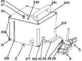
图4为耦合剂添加组件的结构示意图。Fig. 4 is a schematic structural diagram of a coupling agent adding component.
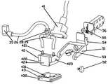
图5为探头组件和探头夹持组件的结构示意图。Fig. 5 is a structural schematic diagram of the probe assembly and the probe clamping assembly.
图中标记的含义如下:1为耦合剂;The meanings of the marks in the figure are as follows: 1 is coupling agent;
2为耦合剂添加组件,21为箱体,211为万向球,212为耦合剂室,213为微型水泵室,214为控制板室,215为液位计,216为耦合剂输出孔,217为控制线孔,218为固定孔,219为安装孔;2 is the couplant adding component, 21 is the box body, 211 is the universal ball, 212 is the couplant chamber, 213 is the micro pump chamber, 214 is the control board chamber, 215 is the liquid level gauge, 216 is the couplant output hole, 217 is Control line hole, 218 is a fixing hole, and 219 is an installation hole;
22为微型水泵,23为耦合剂室盖,231为软管,232为配重球,233为添加孔,234为固定孔;22 is a miniature water pump, 23 is a couplant chamber cover, 231 is a flexible pipe, 232 is a counterweight ball, 233 is an adding hole, and 234 is a fixing hole;
24为箱体盖,241为手柄,242为输出孔,243为输入孔;24 is a box cover, 241 is a handle, 242 is an output hole, and 243 is an input hole;
25为导管,26为软管,27为第一止回阀,28为第二止回阀,29为三通管;25 is a conduit, 26 is a flexible pipe, 27 is a first check valve, 28 is a second check valve, and 29 is a three-way pipe;
3为添加控制组件,31为控制板,32为电源及控制线,33为微型流量计;3 is adding a control assembly, 31 is a control board, 32 is a power supply and a control line, and 33 is a micro flow meter;
4为探头组件,41为相控阵探头,42为有机玻璃块,421为耦合剂输入孔,422为槽,423为夹持孔,424为声能吸收块;43为软套,431为内侧孔,432为槽;4 is the probe assembly, 41 is the phased array probe, 42 is the plexiglass block, 421 is the couplant input hole, 422 is the groove, 423 is the clamping hole, 424 is the sound energy absorption block; 43 is the soft cover, 431 is the inner side Holes, 432 are grooves;
5为探头夹持组件5,51为探头夹,52为楔块固定螺母,53为探头夹固定轴,54为扭簧安装件,55为扭簧,56为探头夹手柄。5 is a
具体实施方式Detailed ways
如图1-5所示,一种基于超声相控阵技术的变曲率构件接触式检测用耦合系统主要由耦合剂1、耦合剂添加组件2、添加控制组件3、探头组件4、探头夹持组件5组成,所述耦合剂1通过所述耦合剂添加组件2添加到所述探头组件4处进行耦合,所述添加控制组件3对所述耦合剂添加组件2进行控制、反馈、调节,所述探头组件4通过探头夹持组件5进行夹持。As shown in Figure 1-5, a coupling system for contact detection of variable curvature components based on ultrasonic phased array technology is mainly composed of coupling agent 1, coupling
本发明实施例中使用的耦合剂1是将粘稠状的甘油与纯净水以适当比例混合,既保证耦合剂的粘稠度,在探头处不快速流动,又保证耦合剂流动性,使耦合剂能进行自动添加。The coupling agent 1 used in the embodiment of the present invention is to mix viscous glycerin and pure water in an appropriate proportion, which not only ensures the viscosity of the coupling agent, does not flow quickly at the probe, but also ensures the fluidity of the coupling agent, so that the coupling Agents can be added automatically.
耦合剂添加组件2包括箱体21、微型水泵22、耦合剂室盖23、箱体盖24、导管25、软管26、第一止回阀27、第二止回阀28、三通29,所述箱体21下装配有三个万向球211,适应箱体在曲面上贴合推行。The
箱体21分为三个区室,分别为耦合剂室212盛装耦合剂、微型水泵室213安放微型水泵、控制板室214安放控制板,耦合剂容器212外附有液位计215,箱体水平放置时可通过液位计观察耦合剂室内的耦合剂量。箱体上有耦合剂输出孔216、控制线孔217、固定孔218、安装孔219。The
耦合剂室盖23上有软管231、重球232、添加孔233、固定孔234,添加孔外连接第一止回阀27,第一止回阀向耦合剂室内部导通,可以往耦合剂室内添加耦合剂,当耦合剂室内耦合剂减小压力下降时空气也可流入。用螺栓通过固定孔将耦合剂室盖安装在耦合剂室上方使其密封,软管一端通过耦合剂室盖通向箱体外,另一侧连接重球,重球上至少有两个孔分布在不同方向从重球外连接到重球内软管孔上,耦合剂通过重球再通过软管输出,重球在重力作用下始终保持在耦合剂室的最低位置,以适应装置多姿态运行,同时重球上至少两个孔,即使有孔与耦合剂室内部表面吸合在一起,依然有其他小孔可通过耦合剂。There is a
箱体盖24上有手柄241、耦合剂室输出孔242、耦合剂水泵输入孔243以及若干固定孔,通过固定孔可用螺栓将箱体盖和箱体固定,可通过手柄将箱体在受检面上推着行走,也可将整个装置提起,使用方便,通过导管25可将耦合剂从耦合剂室输出孔242输到耦合剂水泵输入孔243。所述微型水泵22安放在箱体上的微型水泵室213内,微型水泵输入一侧同耦合剂水泵输入孔243相连,输出一侧通过箱体上的耦合剂输出孔216输出。The
添加控制组件3包括上位机、控制板31、电源及控制线32、微型流量计33,控制板安装在箱体的控制板室,电源及控制线从箱体的控制线孔217引入箱体内,对微型水泵供电并对控制板供电和输送上位机命令,上位机对控制板发送耦合剂流量指令,控制板通过安放在耦合剂输出孔216附近的微型流量计测量的耦合剂输出流量来调节微型水泵的泵速,实现耦合剂流量的控制反馈调节。Add control assembly 3 and comprise upper computer,
耦合剂从微型水泵输出后通过软管26、第二止回阀28,再通过三通29分别从两根软管输到探头组件有机玻璃块上的孔内,第二止回阀向探头组件一侧导通,当微型水泵停止工作时,可以防止耦合剂回流,微型水泵下一次工作时便不需要再重新将微型水泵和软管重新填充满耦合剂。After the couplant is output from the micro-pump, it passes through the
探头组件4包括相控阵探头41、有机玻璃块42、软套43,相控阵探头同通过螺栓同有机玻璃块固定在一起,有机玻璃块上有两个耦合剂输入孔421,每个孔径不小于1.5mm,耦合剂则通过软管从此处输入到有机玻璃块内部,有机玻璃块与工件接触一面两侧开槽422,减小探头组件同受检构件硬接触面积,同时有机玻璃块上两侧还有夹持孔423,前端有声能吸收块424,软套由较软的材料做成,软套成“回”字型,套在有机玻璃块两侧槽上并粘接好,软套内侧开孔431,同有机玻璃块的耦合剂出口孔相连,并由两个孔分散为至少4个孔将耦合剂添加到探头组件和工件接触面上,每个孔截面面积不小于1mm2,软套两侧开槽432,使软套和受检面接触的地方更加柔软,耦合剂在添加到软套与受检构件接触的地方受到挤压迅速铺展开,对探头组件行程良好耦合,此结构减小了探头组件与工件硬接触面积,小面积接触使探头组件可在曲面上检测,同时软套会跟着受检面曲率变化而相应的变化,起到了良好的耦合效果,可用于变曲率构件检测。The probe assembly 4 includes a phased
探头夹持组件5包括探头夹51、楔块固定螺母52、探头夹固定轴53、扭簧安装件43、扭簧55、探头夹手柄56,楔块固定螺母前端一段没有螺纹,楔块固定螺母通过有螺纹一段拧在探头夹上,没有螺纹的一段伸入楔块两侧夹持孔423上,探头组件可同探头夹相互旋转,探头夹固定轴53穿过探头夹,并用螺栓将探头夹固定轴与扭簧安装件固定,探头夹可饶探头夹固定轴旋转,探头夹手柄与扭簧安装件通过螺栓固定,扭簧套在螺栓上安放在探头夹手柄与扭簧安装件之间,使两者能相互旋转且有弹力,探头夹手柄外形为流线型手柄状,其一侧为平面,另一侧为曲面,探头夹手柄上有螺栓固定孔,可以人工握住使用,也可安装自动爬行装置使用,探头夹手柄固定后探头组件在扭簧作用下产生一个压向受检构件的扭力使探头组件与受检构件贴合,两个旋转自由度使探头组件能适应曲面变化。The
探头夹手柄也可同箱体上固定孔218固定配合使用,使用者推着箱体盖上的手柄即可进行检测,使用方便。The probe clamp handle can also be used in conjunction with the fixing
以水轮机转轮叶片上进行检测为例,具体讲述本发明的超声相控阵检测耦合系统的使用过程。Taking the detection on the turbine runner blade as an example, the use process of the ultrasonic phased array detection coupling system of the present invention is described in detail.
叶片正压侧为凹面,背压侧为凸面,靠近入水边和出水边曲率较小,而在中间也变会随着焊缝的弯曲变化而曲率变大,叶片在与焊缝成任意角度方向曲率均为无规律变化,整个叶片呈现变曲率结构特征,检测过程中探头会呈现多姿态检测。The positive pressure side of the blade is concave, and the back pressure side is convex. The curvature is small near the water inlet and outlet edges, and the curvature becomes larger with the curvature of the weld in the middle. The blade is in any angle direction with the weld The curvature changes irregularly, and the entire blade presents a variable curvature structural feature, and the probe will present multi-attitude detection during the detection process.
整套系统连接好后,先将耦合剂从第一止回阀处加入耦合剂室,由于第一止回阀向耦合剂室内部单向导通,因此耦合剂可以加入其中但不会逆向流出,测试系统时,根据探头姿态和移动速度来计算耦合剂最大需求量,通过上位机向控制板输出耦合剂最大需求量控制命令,控制板根据上位机流量命令驱动微型水泵运行,由于重球通过软管、导管与微型水泵入水端连接,因此在重球上的孔口形成负压,耦合剂从重球中吸入,从微型水泵输出端输出,通过微型流量计时记录流速并反馈给控制板,控制板通过改变微型水泵泵速,使其接近预期流速。耦合剂通过微型流量计、软管、第二止回阀、三通后分别从有机玻璃块上的两个输入孔流入有机玻璃块,再流入软套,最后在流出软套。当测试结束后停下微型水泵,第二止回阀会阻止软管内的耦合剂回流,下次使用时便不必先将整个软管充满。After the whole system is connected, the couplant is firstly added to the couplant chamber from the first check valve. Since the first check valve leads to the interior of the couplant chamber in one direction, the couplant can be added into it but will not flow out in reverse. Test When the system is running, the maximum demand for couplant is calculated according to the attitude and moving speed of the probe, and the control command for the maximum demand for couplant is output to the control board through the host computer, and the control board drives the micro pump to run according to the flow command of the host computer. , The conduit is connected to the water inlet of the micro-water pump, so a negative pressure is formed at the orifice on the heavy ball, the couplant is sucked in from the heavy ball, and output from the output of the micro-water pump, the flow rate is recorded by the micro-flow meter and fed back to the control board, and the control board passes Change the pump speed of the micropump so that it is close to the expected flow rate. The couplant flows into the plexiglass block from the two input holes on the plexiglass block through the micro flow meter, the hose, the second check valve and the tee, then flows into the soft cover, and finally flows out of the soft cover. When the micro water pump is stopped after the test is over, the second check valve will prevent the couplant in the hose from flowing back, so it is not necessary to fill the entire hose for the next use.
本系统有三种使用方法。There are three ways to use this system.
方法一,自动检测:配合自动爬行装置,探头夹持手柄平面一面通过螺栓固定孔与自动爬行装置固定,耦合剂添加组件也可通过固定孔安装在自动爬行装置上,将软套贴在叶片上,手握探头夹手柄沿着叶片表面运动,扭簧扭力使有机玻璃楔块、软套同叶片接触的一面良好贴合,耦合剂进行自动添加,便可进行耦合检测,由于有机玻璃块同叶片硬接触面积较小,在凹面曲率较小处检测时耦合良好,当到凹面曲率较大时,软套跟着叶片表面变形,依然可以良好耦合,起到变曲率构件表面良好检测的效果。若想减轻自动爬行装置重量,可加长微型流量计和第二止回阀之间的软管从而使耦合剂添加组件不跟着装置行走。Method 1, automatic detection: Cooperate with the automatic crawling device, the flat side of the probe clamping handle is fixed with the automatic crawling device through the bolt fixing hole, the coupling agent adding component can also be installed on the automatic crawling device through the fixing hole, and the soft cover is pasted on the blade , hold the handle of the probe clamp and move along the surface of the blade. The torsion spring makes the side of the plexiglass wedge and the soft sleeve in contact with the blade fit well. The coupling agent is added automatically, and the coupling detection can be carried out. The hard contact area is small, and the coupling is good when the concave surface curvature is small. When the concave surface curvature is large, the soft sleeve deforms with the blade surface, and it can still be well coupled, which has the effect of good detection on the surface of the variable curvature component. If it is desired to reduce the weight of the automatic crawling device, the hose between the micro flow meter and the second check valve can be lengthened so that the couplant adding component does not follow the device.
方法二,手工检测,耦合剂添加组件跟着行走:将探头夹手柄上平面一面与耦合剂箱体上安装孔219配合固定,此时则可手握箱体盖上的手柄使三个万向球和有机玻璃块、软套与叶片表面贴合,自动添加耦合剂,手握箱体上手柄推着运动即可进行检测,使用方便。当叶片表面姿态发生变化时,在重球重力作用下,重球是在在耦合剂室的最低点,适应多姿态检测,重球上有多个孔,若某个孔与耦合剂室的某个面贴合而无法通过耦合剂,其他孔可以顺利通过耦合剂。
方法三,手工检测,耦合剂添加组件不跟着运行:由于耦合剂添加组件不跟着探头行走,因此需要将微型流量计与第二止回阀之间的软管加长,若耦合剂需求量较大,可将导管取下,直接从外接容器用软管从耦合剂水泵输入孔处与微型水泵输入端连接。Method 3, manual detection, the couplant adding component does not follow the operation: Since the couplant adding component does not follow the probe, it is necessary to lengthen the hose between the micro flowmeter and the second check valve, if the demand for couplant is large , the conduit can be removed, and directly connected to the input end of the micro water pump from the input hole of the couplant water pump with a hose from the external container.
Claims (8)
Priority Applications (1)
| Application Number | Priority Date | Filing Date | Title |
|---|---|---|---|
| CN201310697179.6ACN103675109B (en) | 2013-12-18 | 2013-12-18 | Based on the variable curvature member contact formula detection coupled system of ultrasonic phased array technology |
Applications Claiming Priority (1)
| Application Number | Priority Date | Filing Date | Title |
|---|---|---|---|
| CN201310697179.6ACN103675109B (en) | 2013-12-18 | 2013-12-18 | Based on the variable curvature member contact formula detection coupled system of ultrasonic phased array technology |
Publications (2)
| Publication Number | Publication Date |
|---|---|
| CN103675109Atrue CN103675109A (en) | 2014-03-26 |
| CN103675109B CN103675109B (en) | 2015-11-18 |
Family
ID=50313306
Family Applications (1)
| Application Number | Title | Priority Date | Filing Date |
|---|---|---|---|
| CN201310697179.6AExpired - Fee RelatedCN103675109B (en) | 2013-12-18 | 2013-12-18 | Based on the variable curvature member contact formula detection coupled system of ultrasonic phased array technology |
Country Status (1)
| Country | Link |
|---|---|
| CN (1) | CN103675109B (en) |
Cited By (10)
| Publication number | Priority date | Publication date | Assignee | Title |
|---|---|---|---|---|
| CN104807891A (en)* | 2015-05-14 | 2015-07-29 | 爱德森(厦门)电子有限公司 | Device for identifying continuity of specially-shaped part by utilizing acoustic spectral analysis |
| CN105181796A (en)* | 2015-07-17 | 2015-12-23 | 河海大学 | Probe combination apparatus for testing strength of concrete |
| CN108535364A (en)* | 2018-04-12 | 2018-09-14 | 中车长春轨道客车股份有限公司 | Ultrasonic probe attitude-adaptive electro-optical feedback closed loop regulating device and method |
| CN108577885A (en)* | 2017-12-06 | 2018-09-28 | 浙江大学 | A kind of supersonic detection device |
| CN108663607A (en)* | 2018-06-21 | 2018-10-16 | 国网江苏省电力有限公司电力科学研究院 | A kind of shelf depreciation ultrasound examination couplant automatic adding device and method |
| CN113030266A (en)* | 2021-03-25 | 2021-06-25 | 武汉理工大学 | Automobile third-generation hub bearing outer ring ultrasonic phased array detection device and method |
| CN114019032A (en)* | 2021-11-16 | 2022-02-08 | 西安热工研究院有限公司 | Auxiliary device and method for ultrasonic detection of couplant on compressor blade |
| CN114878693A (en)* | 2022-03-29 | 2022-08-09 | 中国兵器科学研究院宁波分院 | Portable phased array ultrasonic scanning device and scanning method thereof |
| CN117685915A (en)* | 2024-02-02 | 2024-03-12 | 常州市智鸿机械有限公司 | Device for detecting cambered surface of blade crown of turbine blade |
| CN120352520A (en)* | 2025-06-23 | 2025-07-22 | 西安顺世鑫工贸有限公司 | Screw production detection device and method |
Citations (7)
| Publication number | Priority date | Publication date | Assignee | Title |
|---|---|---|---|---|
| JPH07318539A (en)* | 1994-05-24 | 1995-12-08 | Fuji Electric Co Ltd | Ultrasonic flaw detector |
| JP2003028847A (en)* | 2001-07-12 | 2003-01-29 | Hitachi Eng Co Ltd | High viscosity couplant feeder and ultrasonic flaw detector using the same |
| JP2004028762A (en)* | 2002-06-25 | 2004-01-29 | Osaka Gas Co Ltd | Method and device for ultrasonic flaw detection |
| CN102520074A (en)* | 2011-12-30 | 2012-06-27 | 西南交通大学 | Automatic couplant supply system for ultrasonic probe |
| CN202486104U (en)* | 2012-01-04 | 2012-10-10 | 华北电力科学研究院有限责任公司 | A system for detecting fir-tree-shaped blade roots of steam turbines |
| CN202740612U (en)* | 2012-08-22 | 2013-02-20 | 山东贝诺医药生物科技有限公司 | Dosing device |
| JP5356857B2 (en)* | 2009-02-17 | 2013-12-04 | 日立Geニュークリア・エナジー株式会社 | Ultrasonic probe shoe and method for removing ultrasonic probe |
- 2013
- 2013-12-18CNCN201310697179.6Apatent/CN103675109B/ennot_activeExpired - Fee Related
Patent Citations (7)
| Publication number | Priority date | Publication date | Assignee | Title |
|---|---|---|---|---|
| JPH07318539A (en)* | 1994-05-24 | 1995-12-08 | Fuji Electric Co Ltd | Ultrasonic flaw detector |
| JP2003028847A (en)* | 2001-07-12 | 2003-01-29 | Hitachi Eng Co Ltd | High viscosity couplant feeder and ultrasonic flaw detector using the same |
| JP2004028762A (en)* | 2002-06-25 | 2004-01-29 | Osaka Gas Co Ltd | Method and device for ultrasonic flaw detection |
| JP5356857B2 (en)* | 2009-02-17 | 2013-12-04 | 日立Geニュークリア・エナジー株式会社 | Ultrasonic probe shoe and method for removing ultrasonic probe |
| CN102520074A (en)* | 2011-12-30 | 2012-06-27 | 西南交通大学 | Automatic couplant supply system for ultrasonic probe |
| CN202486104U (en)* | 2012-01-04 | 2012-10-10 | 华北电力科学研究院有限责任公司 | A system for detecting fir-tree-shaped blade roots of steam turbines |
| CN202740612U (en)* | 2012-08-22 | 2013-02-20 | 山东贝诺医药生物科技有限公司 | Dosing device |
Cited By (13)
| Publication number | Priority date | Publication date | Assignee | Title |
|---|---|---|---|---|
| CN104807891A (en)* | 2015-05-14 | 2015-07-29 | 爱德森(厦门)电子有限公司 | Device for identifying continuity of specially-shaped part by utilizing acoustic spectral analysis |
| CN105181796A (en)* | 2015-07-17 | 2015-12-23 | 河海大学 | Probe combination apparatus for testing strength of concrete |
| CN105181796B (en)* | 2015-07-17 | 2017-11-14 | 河海大学 | A kind of probe combination unit for being used to test concrete strength |
| CN108577885A (en)* | 2017-12-06 | 2018-09-28 | 浙江大学 | A kind of supersonic detection device |
| CN108535364A (en)* | 2018-04-12 | 2018-09-14 | 中车长春轨道客车股份有限公司 | Ultrasonic probe attitude-adaptive electro-optical feedback closed loop regulating device and method |
| CN108663607B (en)* | 2018-06-21 | 2023-09-08 | 国网江苏省电力有限公司电力科学研究院 | Automatic adding device and method for partial discharge ultrasonic detection couplant |
| CN108663607A (en)* | 2018-06-21 | 2018-10-16 | 国网江苏省电力有限公司电力科学研究院 | A kind of shelf depreciation ultrasound examination couplant automatic adding device and method |
| CN113030266A (en)* | 2021-03-25 | 2021-06-25 | 武汉理工大学 | Automobile third-generation hub bearing outer ring ultrasonic phased array detection device and method |
| CN114019032A (en)* | 2021-11-16 | 2022-02-08 | 西安热工研究院有限公司 | Auxiliary device and method for ultrasonic detection of couplant on compressor blade |
| CN114878693A (en)* | 2022-03-29 | 2022-08-09 | 中国兵器科学研究院宁波分院 | Portable phased array ultrasonic scanning device and scanning method thereof |
| CN117685915A (en)* | 2024-02-02 | 2024-03-12 | 常州市智鸿机械有限公司 | Device for detecting cambered surface of blade crown of turbine blade |
| CN117685915B (en)* | 2024-02-02 | 2024-04-19 | 常州市智鸿机械有限公司 | Device for detecting cambered surface of blade crown of turbine blade |
| CN120352520A (en)* | 2025-06-23 | 2025-07-22 | 西安顺世鑫工贸有限公司 | Screw production detection device and method |
Also Published As
| Publication number | Publication date |
|---|---|
| CN103675109B (en) | 2015-11-18 |
Similar Documents
| Publication | Publication Date | Title |
|---|---|---|
| CN103675109B (en) | Based on the variable curvature member contact formula detection coupled system of ultrasonic phased array technology | |
| CN1654863A (en) | Flow control valve and flow control device | |
| CN108827591B (en) | Gravity type circulating water tunnel for drag reduction measurement of underwater complex surface | |
| CN102998087B (en) | Resistance testing device suitable for jet flow surface and non-smooth surface | |
| CN103776613B (en) | Assess assay device and the method for bionical jet surface resistance reducing performance | |
| CN103543077A (en) | Injection type erosion corrosion testing device | |
| CN106092505B (en) | A kind of test device of the drag reduction surface based on bionical jet stream | |
| CN206348352U (en) | A kind of sample charging mechanism of micro automatic sample adding instrument | |
| US20230296082A1 (en) | Integrated multidirectional loading model test device for offshore wind turbines | |
| CN208206436U (en) | A kind of gravity type circulating water tunnel for the measurement of underwater complex surface drag reduction | |
| CN204027536U (en) | Electromagnet type pulse-echo ultrasound ripple thicknessmeter servicing unit | |
| CN103759918A (en) | Test device and method for evaluating bionic jet flow surface panel friction reduction effect | |
| US20150153264A1 (en) | Corrosion- resistant test device | |
| JP2012177682A (en) | Water seal type probe holding device and inspection method using the same | |
| CN108844714A (en) | A kind of the bionic non-smooth surface drag reduction test device and simulator of variable curvature | |
| CN112161769A (en) | Horizontal two-degree-of-freedom hydraulic pump vibration acceleration life test stand | |
| CN104458140A (en) | Automobile part waterproof test equipment with adjustable angle | |
| CN103759919A (en) | Device and method for testing biomimetic jet surface fluid frictional resistance | |
| Zahari et al. | Design and development of low-cost water tunnel for educational purpose | |
| KR20120072233A (en) | Non-destructive inspection device equipped with couplant supplying apparatus | |
| CN201688876U (en) | Structural member capable of accurately locating ultrasonic reflection sheet | |
| CN110567997A (en) | A vacuum cavity assembly for a scattering experiment station | |
| US20210318269A1 (en) | Self misting wedge | |
| CN108621104A (en) | A kind of Big Diameter Flange face docking floating support device | |
| CN104655209A (en) | Ultrasonic water meter with flow rate control function |
Legal Events
| Date | Code | Title | Description |
|---|---|---|---|
| PB01 | Publication | ||
| PB01 | Publication | ||
| C10 | Entry into substantive examination | ||
| SE01 | Entry into force of request for substantive examination | ||
| C14 | Grant of patent or utility model | ||
| GR01 | Patent grant | ||
| CF01 | Termination of patent right due to non-payment of annual fee | ||
| CF01 | Termination of patent right due to non-payment of annual fee | Granted publication date:20151118 |