CN103649676A - Six-DoF Laser Tracker Collaborating with Remote Structured Light Scanner - Google Patents
Six-DoF Laser Tracker Collaborating with Remote Structured Light ScannerDownload PDFInfo
- Publication number
- CN103649676A CN103649676ACN201280018679.6ACN201280018679ACN103649676ACN 103649676 ACN103649676 ACN 103649676ACN 201280018679 ACN201280018679 ACN 201280018679ACN 103649676 ACN103649676 ACN 103649676A
- Authority
- CN
- China
- Prior art keywords
- light
- pattern
- projector
- retroreflector
- source
- Prior art date
- Legal status (The legal status is an assumption and is not a legal conclusion. Google has not performed a legal analysis and makes no representation as to the accuracy of the status listed.)
- Pending
Links
Images


Classifications
- G—PHYSICS
- G01—MEASURING; TESTING
- G01B—MEASURING LENGTH, THICKNESS OR SIMILAR LINEAR DIMENSIONS; MEASURING ANGLES; MEASURING AREAS; MEASURING IRREGULARITIES OF SURFACES OR CONTOURS
- G01B11/00—Measuring arrangements characterised by the use of optical techniques
- G01B11/02—Measuring arrangements characterised by the use of optical techniques for measuring length, width or thickness
- G01B11/03—Measuring arrangements characterised by the use of optical techniques for measuring length, width or thickness by measuring coordinates of points
- G—PHYSICS
- G01—MEASURING; TESTING
- G01B—MEASURING LENGTH, THICKNESS OR SIMILAR LINEAR DIMENSIONS; MEASURING ANGLES; MEASURING AREAS; MEASURING IRREGULARITIES OF SURFACES OR CONTOURS
- G01B11/00—Measuring arrangements characterised by the use of optical techniques
- G—PHYSICS
- G01—MEASURING; TESTING
- G01B—MEASURING LENGTH, THICKNESS OR SIMILAR LINEAR DIMENSIONS; MEASURING ANGLES; MEASURING AREAS; MEASURING IRREGULARITIES OF SURFACES OR CONTOURS
- G01B11/00—Measuring arrangements characterised by the use of optical techniques
- G01B11/24—Measuring arrangements characterised by the use of optical techniques for measuring contours or curvatures
- G01B11/25—Measuring arrangements characterised by the use of optical techniques for measuring contours or curvatures by projecting a pattern, e.g. one or more lines, moiré fringes on the object
- G—PHYSICS
- G01—MEASURING; TESTING
- G01C—MEASURING DISTANCES, LEVELS OR BEARINGS; SURVEYING; NAVIGATION; GYROSCOPIC INSTRUMENTS; PHOTOGRAMMETRY OR VIDEOGRAMMETRY
- G01C15/00—Surveying instruments or accessories not provided for in groups G01C1/00 - G01C13/00
- G01C15/002—Active optical surveying means
- G—PHYSICS
- G01—MEASURING; TESTING
- G01B—MEASURING LENGTH, THICKNESS OR SIMILAR LINEAR DIMENSIONS; MEASURING ANGLES; MEASURING AREAS; MEASURING IRREGULARITIES OF SURFACES OR CONTOURS
- G01B11/00—Measuring arrangements characterised by the use of optical techniques
- G01B11/02—Measuring arrangements characterised by the use of optical techniques for measuring length, width or thickness
- G—PHYSICS
- G01—MEASURING; TESTING
- G01B—MEASURING LENGTH, THICKNESS OR SIMILAR LINEAR DIMENSIONS; MEASURING ANGLES; MEASURING AREAS; MEASURING IRREGULARITIES OF SURFACES OR CONTOURS
- G01B11/00—Measuring arrangements characterised by the use of optical techniques
- G01B11/26—Measuring arrangements characterised by the use of optical techniques for measuring angles or tapers; for testing the alignment of axes
- G01B11/27—Measuring arrangements characterised by the use of optical techniques for measuring angles or tapers; for testing the alignment of axes for testing the alignment of axes
- G—PHYSICS
- G01—MEASURING; TESTING
- G01B—MEASURING LENGTH, THICKNESS OR SIMILAR LINEAR DIMENSIONS; MEASURING ANGLES; MEASURING AREAS; MEASURING IRREGULARITIES OF SURFACES OR CONTOURS
- G01B5/00—Measuring arrangements characterised by the use of mechanical techniques
- G01B5/004—Measuring arrangements characterised by the use of mechanical techniques for measuring coordinates of points
- G01B5/008—Measuring arrangements characterised by the use of mechanical techniques for measuring coordinates of points using coordinate measuring machines
- G01B5/012—Contact-making feeler heads therefor
- G—PHYSICS
- G01—MEASURING; TESTING
- G01C—MEASURING DISTANCES, LEVELS OR BEARINGS; SURVEYING; NAVIGATION; GYROSCOPIC INSTRUMENTS; PHOTOGRAMMETRY OR VIDEOGRAMMETRY
- G01C3/00—Measuring distances in line of sight; Optical rangefinders
- G01C3/02—Details
- G01C3/06—Use of electric means to obtain final indication
- G01C3/08—Use of electric radiation detectors
- G—PHYSICS
- G01—MEASURING; TESTING
- G01S—RADIO DIRECTION-FINDING; RADIO NAVIGATION; DETERMINING DISTANCE OR VELOCITY BY USE OF RADIO WAVES; LOCATING OR PRESENCE-DETECTING BY USE OF THE REFLECTION OR RERADIATION OF RADIO WAVES; ANALOGOUS ARRANGEMENTS USING OTHER WAVES
- G01S17/00—Systems using the reflection or reradiation of electromagnetic waves other than radio waves, e.g. lidar systems
- G01S17/02—Systems using the reflection of electromagnetic waves other than radio waves
- G01S17/06—Systems determining position data of a target
- G01S17/42—Simultaneous measurement of distance and other co-ordinates
- G—PHYSICS
- G01—MEASURING; TESTING
- G01S—RADIO DIRECTION-FINDING; RADIO NAVIGATION; DETERMINING DISTANCE OR VELOCITY BY USE OF RADIO WAVES; LOCATING OR PRESENCE-DETECTING BY USE OF THE REFLECTION OR RERADIATION OF RADIO WAVES; ANALOGOUS ARRANGEMENTS USING OTHER WAVES
- G01S17/00—Systems using the reflection or reradiation of electromagnetic waves other than radio waves, e.g. lidar systems
- G01S17/66—Tracking systems using electromagnetic waves other than radio waves
- G—PHYSICS
- G01—MEASURING; TESTING
- G01S—RADIO DIRECTION-FINDING; RADIO NAVIGATION; DETERMINING DISTANCE OR VELOCITY BY USE OF RADIO WAVES; LOCATING OR PRESENCE-DETECTING BY USE OF THE REFLECTION OR RERADIATION OF RADIO WAVES; ANALOGOUS ARRANGEMENTS USING OTHER WAVES
- G01S17/00—Systems using the reflection or reradiation of electromagnetic waves other than radio waves, e.g. lidar systems
- G01S17/88—Lidar systems specially adapted for specific applications
- G01S17/89—Lidar systems specially adapted for specific applications for mapping or imaging
- G—PHYSICS
- G01—MEASURING; TESTING
- G01S—RADIO DIRECTION-FINDING; RADIO NAVIGATION; DETERMINING DISTANCE OR VELOCITY BY USE OF RADIO WAVES; LOCATING OR PRESENCE-DETECTING BY USE OF THE REFLECTION OR RERADIATION OF RADIO WAVES; ANALOGOUS ARRANGEMENTS USING OTHER WAVES
- G01S7/00—Details of systems according to groups G01S13/00, G01S15/00, G01S17/00
- G01S7/02—Details of systems according to groups G01S13/00, G01S15/00, G01S17/00 of systems according to group G01S13/00
- G01S7/42—Diversity systems specially adapted for radar
- G—PHYSICS
- G01—MEASURING; TESTING
- G01S—RADIO DIRECTION-FINDING; RADIO NAVIGATION; DETERMINING DISTANCE OR VELOCITY BY USE OF RADIO WAVES; LOCATING OR PRESENCE-DETECTING BY USE OF THE REFLECTION OR RERADIATION OF RADIO WAVES; ANALOGOUS ARRANGEMENTS USING OTHER WAVES
- G01S7/00—Details of systems according to groups G01S13/00, G01S15/00, G01S17/00
- G01S7/48—Details of systems according to groups G01S13/00, G01S15/00, G01S17/00 of systems according to group G01S17/00
- G01S7/4808—Evaluating distance, position or velocity data
- G—PHYSICS
- G01—MEASURING; TESTING
- G01S—RADIO DIRECTION-FINDING; RADIO NAVIGATION; DETERMINING DISTANCE OR VELOCITY BY USE OF RADIO WAVES; LOCATING OR PRESENCE-DETECTING BY USE OF THE REFLECTION OR RERADIATION OF RADIO WAVES; ANALOGOUS ARRANGEMENTS USING OTHER WAVES
- G01S7/00—Details of systems according to groups G01S13/00, G01S15/00, G01S17/00
- G01S7/48—Details of systems according to groups G01S13/00, G01S15/00, G01S17/00 of systems according to group G01S17/00
- G01S7/481—Constructional features, e.g. arrangements of optical elements
- G01S7/4811—Constructional features, e.g. arrangements of optical elements common to transmitter and receiver
- G01S7/4813—Housing arrangements
- G—PHYSICS
- G01—MEASURING; TESTING
- G01S—RADIO DIRECTION-FINDING; RADIO NAVIGATION; DETERMINING DISTANCE OR VELOCITY BY USE OF RADIO WAVES; LOCATING OR PRESENCE-DETECTING BY USE OF THE REFLECTION OR RERADIATION OF RADIO WAVES; ANALOGOUS ARRANGEMENTS USING OTHER WAVES
- G01S7/00—Details of systems according to groups G01S13/00, G01S15/00, G01S17/00
- G01S7/48—Details of systems according to groups G01S13/00, G01S15/00, G01S17/00 of systems according to group G01S17/00
- G01S7/481—Constructional features, e.g. arrangements of optical elements
- G01S7/4818—Constructional features, e.g. arrangements of optical elements using optical fibres
- G—PHYSICS
- G01—MEASURING; TESTING
- G01S—RADIO DIRECTION-FINDING; RADIO NAVIGATION; DETERMINING DISTANCE OR VELOCITY BY USE OF RADIO WAVES; LOCATING OR PRESENCE-DETECTING BY USE OF THE REFLECTION OR RERADIATION OF RADIO WAVES; ANALOGOUS ARRANGEMENTS USING OTHER WAVES
- G01S7/00—Details of systems according to groups G01S13/00, G01S15/00, G01S17/00
- G01S7/48—Details of systems according to groups G01S13/00, G01S15/00, G01S17/00 of systems according to group G01S17/00
- G01S7/491—Details of non-pulse systems
- G—PHYSICS
- G06—COMPUTING OR CALCULATING; COUNTING
- G06F—ELECTRIC DIGITAL DATA PROCESSING
- G06F17/00—Digital computing or data processing equipment or methods, specially adapted for specific functions
- G06F17/40—Data acquisition and logging
- G—PHYSICS
- G16—INFORMATION AND COMMUNICATION TECHNOLOGY [ICT] SPECIALLY ADAPTED FOR SPECIFIC APPLICATION FIELDS
- G16Z—INFORMATION AND COMMUNICATION TECHNOLOGY [ICT] SPECIALLY ADAPTED FOR SPECIFIC APPLICATION FIELDS, NOT OTHERWISE PROVIDED FOR
- G16Z99/00—Subject matter not provided for in other main groups of this subclass
Landscapes
- Engineering & Computer Science (AREA)
- Physics & Mathematics (AREA)
- General Physics & Mathematics (AREA)
- Radar, Positioning & Navigation (AREA)
- Remote Sensing (AREA)
- Computer Networks & Wireless Communication (AREA)
- Electromagnetism (AREA)
- Computer Vision & Pattern Recognition (AREA)
- Length Measuring Devices By Optical Means (AREA)
- Optical Radar Systems And Details Thereof (AREA)
- Length Measuring Devices With Unspecified Measuring Means (AREA)
- Measurement Of Optical Distance (AREA)
- Position Input By Displaying (AREA)
Abstract
Description
Translated fromChinese相关申请的交叉引用Cross References to Related Applications
本申请要求2012年1月30日提交的美国临时专利申请No.61/592,049和2011年4月15日提交的美国临时专利申请No.61/475,703的优先权,在此通过引用并入这两个申请的全部内容。This application claims priority to U.S. Provisional Patent Application No. 61/592,049, filed January 30, 2012, and U.S. Provisional Patent Application No. 61/475,703, filed April 15, 2011, both of which are hereby incorporated by reference. the entire content of the application.
背景技术Background technique
本公开涉及坐标测量装置。一组坐标测量装置属于通过向点发送激光束来测量该点的三维(3D)坐标的一类仪器。该激光束可能直接照射在该点上或照射在与该点相接触的回射器目标上。在任一情况下,该仪器通过测量到该目标的距离和两个角来确定该点的坐标。该距离是利用诸如绝对距离仪或干涉仪的测距装置来测量的。这些角是利用诸如角编码器的角测装置来测量的。该仪器内的万向光束转向机构使激光束指向关注点。The present disclosure relates to coordinate measuring devices. A group of coordinate measuring devices is a class of instruments that measure the three-dimensional (3D) coordinates of a point by sending a laser beam at the point. The laser beam may impinge directly on the point or on a retroreflector target in contact with the point. In either case, the instrument determines the coordinates of the point by measuring the distance to the target and two angles. The distance is measured using a distance measuring device such as an absolute distance meter or an interferometer. These angles are measured using goniometric devices such as angle encoders. A gimbal beam steering mechanism within the instrument directs the laser beam to the point of interest.
激光追踪器是利用其发射的一个或多个激光束追踪回射器目标的特定类型的坐标测量装置。与激光追踪器紧密相关的坐标测量装置是激光扫描仪和全能测量仪。激光扫描仪使一个或多个激光束移动(step)至表面上的点。激光扫描仪拾取从表面散射的光并且根据该光确定到各点的距离和两个角。勘测应用中最常使用的全能测量仪可以用来测量漫反射或回射目标的坐标。在下文,在广义上使用术语激光追踪器以包括激光扫描仪和全能测量仪。A laser tracker is a specific type of coordinate measurement device that uses one or more laser beams it emits to track a retroreflector target. Coordinate measuring devices that are closely related to laser trackers are laser scanners and universal measuring machines. Laser scanners step one or more laser beams to points on a surface. The laser scanner picks up the light scattered from the surface and from this light determines the distance to each point and the two angles. The most commonly used universal gauges in surveying applications can be used to measure the coordinates of diffuse or retroreflective targets. In the following, the term laser tracker is used in a broad sense to include laser scanners and omnidirectional surveyors.
通常,激光追踪器向回射器目标发送激光束。回射器目标的常用类型是包括嵌入金属球体内的立方隅角回射器的球形安装的回射器(SMR)。立方隅角回射器包括三个相互垂直的镜。作为这三个镜的共同交叉点的顶点位于球体的中心。由于球体内立方隅角的该配置,即使在SMR转动时,从顶点到保持SMR的任何表面的垂直距离保持恒定。结果,激光追踪器可以通过随着SMR在表面上移动而跟踪SMR的位置来测量表面的3D坐标。换言之,激光追踪器仅需要测量三个自由度(一个径向距离和两个角)以完全表征表面的3D坐标。Typically, a laser tracker sends a laser beam at a retroreflector target. A common type of retroreflector target is a spherically mounted retroreflector (SMR) comprising a cube corner retroreflector embedded within a metal sphere. Cube corner retroreflectors consist of three mutually perpendicular mirrors. The vertex, which is the common intersection of these three mirrors, is at the center of the sphere. Due to this configuration of the cube corners within the sphere, the perpendicular distance from the apex to any surface holding the SMR remains constant even as the SMR rotates. As a result, a laser tracker can measure the 3D coordinates of a surface by tracking the position of the SMR as it moves across the surface. In other words, the laser tracker only needs to measure three degrees of freedom (one radial distance and two angles) to fully characterize the 3D coordinates of the surface.
一种类型的激光追踪器仅包括干涉仪(IFM)而不包括绝对距离仪(ADM)。在对象阻断了来自这些追踪器之一的激光束的路径的情况下,IFM丢失其距离参考。于是,操作员必须将回射器追踪至已知位置以在继续测量之前重置至参考距离。绕过这种限制的方式是将ADM置于追踪器中。如以下更详细地所述,ADM可以以对准即拍(point-and-shoot)的方式测量距离。一些激光追踪器仅包含ADM而不具有干涉仪。Bridges等人的美国专利No.7,352,446(‘446)(其内容通过引用并入于此)描述了仅具有能够精确地扫描移动目标的ADM(且无IFM)的追踪器。在‘446专利之前,绝对距离仪过慢而无法准确地找出移动目标的位置。One type of laser tracker includes only an interferometer (IFM) and not an absolute distance meter (ADM). In the event an object blocks the path of the laser beam from one of these trackers, the IFM loses its distance reference. Then, the operator must track the retroreflector to a known location to reset to a reference distance before continuing with the measurement. A way around this limitation is to put the ADM in the tracker. As described in more detail below, the ADM can measure distance in a point-and-shoot manner. Some laser trackers contain only ADMs without interferometers. US Patent No. 7,352,446 ('446) to Bridges et al., the contents of which are incorporated herein by reference, describes a tracker with only an ADM (and no IFM) capable of accurately scanning moving targets. Prior to the '446 patent, absolute range meters were too slow to accurately locate moving targets.
激光追踪器内的万向机构可以用来将来自追踪器的激光束指向SMR。由SMR回射的光的一部分入射到激光追踪器中并且传递至位置检测器上。激光追踪器内的控制系统可以使用光在位置检测器上的位置来调整激光追踪器的机械轴的转动角,以保持激光束在SMR上居中。这样,追踪器能够跟随(追踪)在关注对象的表面上移动的SMR。A gimbal mechanism within the laser tracker can be used to point the laser beam from the tracker at the SMR. A portion of the light retroreflected by the SMR is incident into the laser tracker and passed onto the position detector. A control system within the laser tracker can use the position of the light on the position detector to adjust the rotation angle of the laser tracker's mechanical axis to keep the laser beam centered on the SMR. In this way, the tracker is able to follow (track) the SMR moving on the surface of the object of interest.
将诸如角编码器的角度测量装置附接至追踪器的机械轴。由激光追踪器所进行的一个距离测量和两个角度测量足以完全指定SMR的三维位置。Attach an angle measuring device such as an angle encoder to the mechanical shaft of the tracker. One distance measurement and two angle measurements by the laser tracker are sufficient to fully specify the three-dimensional position of the SMR.
可利用或提出了用以测量六自由度而非普通的三自由度的几种激光追踪器。Bridges等人的美国专利No.7,800,758(‘758)(其全部内容通过引用并入于此)和Bridges等人的美国公开专利申请No.2010/0128259(其全部内容通过引用并入于此)描述了示例性的六自由度(六DOF)系统。Several laser trackers are available or proposed to measure six degrees of freedom instead of the usual three. U.S. Patent No. 7,800,758 ('758) to Bridges et al. (herein incorporated by reference in its entirety) and U.S. Published Patent Application No. 2010/0128259 to Bridges et al. (incorporated herein by reference in its entirety) describe An exemplary six degrees of freedom (six DOF) system is presented.
需要新型的六DOF组件,其在用于六DOF激光追踪器时提供各种性能。There is a need for new six DOF components that provide various properties when used in six DOF laser trackers.
发明内容Contents of the invention
根据本发明的实施例,一种利用坐标测量装置和目标扫描仪来测量对象表面上的三个或更多个表面集的方法,三个或更多个表面集中的每一个是装置参考坐标系内的对象表面上的点的三维坐标,各表面集包括三个值,装置参考坐标系与所述坐标测量装置相关联。该方法包括以下步骤:提供目标传感器,该目标传感器具有主体、第一回射器、投射器、摄像装置和扫描仪处理器,其中第一回射器、投射器和摄像装置刚性地附接至主体,并且目标传感器从坐标测量装置机械地拆卸,投射器包括光源图案和投射器透镜,该光源图案位于源面上并且包括至少三个非共线的图案元素,投射器透镜被配置为将光源图案投射到对象上以在对象上形成光的对象图案,至少三个非共线图案元素各自与至少一个表面集相对应,其中摄像装置包括摄像装置透镜和光敏阵列,该摄像装置透镜被配置为使对象光图案在光敏阵列上成像作为光的图像图案,光敏阵列包括摄像装置像素,光敏阵列被配置为针对各摄像装置像素产生与摄像装置像素从光的图像图案接收到的光量相对应的相应像素数字值。该方法还包括:提供所述坐标测量装置,所述坐标测量装置被配置为测量平移集和方位集,所述平移集是所述目标传感器在所述装置参考坐标系中的三个平移自由度的值并且所述方位集是所述目标传感器在所述装置参考坐标系中的三个方位自由度的值,所述平移集和所述方位集足以限定所述目标传感器在空间内的位置和方位,所述坐标测量装置被配置为将第一光束发送至所述第一回射器并且从所述第一回射器接收第二光束,所述第二光束是所述第一光束的一部分,所述坐标测量装置包括装置处理器,所述装置处理器被配置为确定所述方位集和所述平移集,所述平移集至少部分基于所述第二光束,所述传感器处理器和所述装置处理器共同被配置为确定所述感测特性和所述表面集,所述表面集至少部分基于所述平移集、所述方位集和所述像素数字值。所述方法还包括:选择所述光源图案;将所述光源图案投射到对象上以产生对象光图案;使所述对象光图案在所述光敏阵列上成像以获得光的图像图案;获得光的图像图案的像素数字值;将所述第一光束从所述坐标测量装置发送至所述第一回射器;从所述所述第一回射器接收所述第二光束;至少部分基于所述第二光束来利用所述坐标测量装置测量所述方位集和所述平移集;确定与至少三个非共线图案元素各自相对应的表面集;以及保存所述表面集。According to an embodiment of the present invention, a method of measuring three or more surface sets on a surface of an object using a coordinate measuring device and a target scanner, each of the three or more surface sets being a device reference coordinate system The three-dimensional coordinates of points on the surface of the object within, each surface set comprising three values, a device reference coordinate system associated with the coordinate measuring device. The method includes the steps of: providing an object sensor having a body, a first retroreflector, a projector, a camera, and a scanner processor, wherein the first retroreflector, projector, and camera are rigidly attached to The main body and the target sensor are mechanically detached from the coordinate measuring device, the projector includes a light source pattern located on the source face and includes at least three non-collinear pattern elements, and the projector lens is configured to direct the light source The pattern is projected onto the object to form an object pattern of light on the object, the at least three non-collinear pattern elements each corresponding to at least one surface set, wherein the camera includes a camera lens and a photosensitive array, the camera lens configured to The subject light pattern is imaged as an image pattern of light on a photosensitive array comprising camera pixels, the photosensitive array being configured to generate, for each camera pixel, a response corresponding to the amount of light received by the camera pixel from the image pattern of light. Pixel numeric value. The method also includes providing the coordinate measurement device configured to measure a translation set and an orientation set, the translation set being three translational degrees of freedom of the target sensor in the device reference frame and the orientation set is the value of the three orientation degrees of freedom of the target sensor in the device reference coordinate system, the translation set and the orientation set are sufficient to define the position and position of the target sensor in space Azimuthally, the coordinate measuring device is configured to send a first beam to the first retroreflector and to receive a second beam from the first retroreflector, the second beam being a portion of the first beam , the coordinate measuring device includes a device processor configured to determine the set of orientations and the set of translations based at least in part on the second light beam, the sensor processor and the set of translations The device processors are collectively configured to determine the sensing characteristic and the surface set based at least in part on the translation set, the orientation set, and the pixel digital value. The method also includes: selecting the light source pattern; projecting the light source pattern onto an object to generate an object light pattern; imaging the object light pattern on the photosensitive array to obtain an image pattern of light; obtaining an image pattern of light digital values of pixels of an image pattern; sending the first light beam from the coordinate measuring device to the first retroreflector; receiving the second light beam from the first retroreflector; based at least in part on the measuring the set of orientations and the set of translations with the coordinate measuring device using the second beam; determining a set of surfaces corresponding to each of at least three non-collinear pattern elements; and saving the set of surfaces.
附图说明Description of drawings
现在参考附图,示出了不应当被解释为限制本公开的整个范围的示例性实施例,其中在几个附图中元件被类似地编号:Referring now to the drawings, there are shown exemplary embodiments which should not be construed as limiting the entire scope of the present disclosure, wherein elements are similarly numbered in the several figures:
图1是根据本发明实施例的具有回射器目标的激光追踪器系统的立体图;1 is a perspective view of a laser tracker system with a retroreflector target in accordance with an embodiment of the present invention;
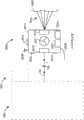
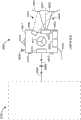
图2是根据本发明实施例的具有六DOF目标的激光追踪器系统的立体图;2 is a perspective view of a laser tracker system with a six DOF target according to an embodiment of the present invention;
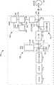
图3是说明根据本发明实施例的激光追踪器的光学和电子学元件的框图;3 is a block diagram illustrating optical and electronic components of a laser tracker according to an embodiment of the invention;
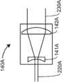
包括图4A和4B的图4示出两种类型的现有技术的无焦光束扩展器;Figure 4, comprising Figures 4A and 4B, shows two types of prior art afocal beam expanders;
图5示出现有技术的光纤光束发射;Figure 5 shows a prior art fiber optic beam launch;
图6A~6D是示出四种类型的现有技术的位置检测器组件的示意图;6A-6D are schematic diagrams showing four types of prior art position detector assemblies;
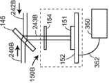
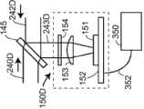
图6E和6F是示出根据本发明的实施例的位置检测器组件的示意图;6E and 6F are schematic diagrams illustrating a position detector assembly according to an embodiment of the present invention;
图7是现有技术的ADM内的电气和光电元件的框图;Figure 7 is a block diagram of electrical and optoelectronic components within a prior art ADM;
图8A和8B是示出现有技术的光纤网络内的光纤元件的示意图;8A and 8B are schematic diagrams illustrating fiber optic components within a prior art fiber optic network;
图8C是示出根据本发明实施例的光纤网络内的光纤元件的示意图;Figure 8C is a schematic diagram illustrating fiber optic components within a fiber optic network according to an embodiment of the invention;
图9是现有技术的激光追踪器的分解图;Fig. 9 is an exploded view of a prior art laser tracker;
图10是现有技术的激光追踪器的截面图;Fig. 10 is a sectional view of a prior art laser tracker;
图11是根据本发明实施例的激光追踪器的计算和通信元件的框图;Figure 11 is a block diagram of the computing and communication elements of a laser tracker according to an embodiment of the invention;
图12A是根据本发明实施例的使用单个波长的激光追踪器中的元件的框图;12A is a block diagram of components in a laser tracker using a single wavelength according to an embodiment of the invention;
图12B是根据本发明实施例的使用单个波长的激光追踪器中的元件的框图;12B is a block diagram of components in a laser tracker using a single wavelength according to an embodiment of the invention;
图13是根据本发明实施例的具有六DOF能力的激光追踪器中的元件的框图;13 is a block diagram of components in a laser tracker with six DOF capability according to an embodiment of the invention;
图14是根据本发明实施例的具有六DOF能力的激光追踪器中的元件的框图;14 is a block diagram of components in a laser tracker with six DOF capability according to an embodiment of the invention;
图15和15C是根据本发明实施例的具有六DOF能力的激光追踪器中的元件的框图;15 and 15C are block diagrams of components in a laser tracker with six DOF capability, according to an embodiment of the invention;
图15A、15B、15D和15E是示出基于三角测量的扫描测量系统的操作原理的示意图;15A, 15B, 15D and 15E are schematic diagrams illustrating the operating principle of a triangulation-based scanning measurement system;
图15F示出根据本发明实施例可以采取的用以确保高质量测量结果的步骤;Figure 15F illustrates steps that may be taken to ensure high quality measurement results in accordance with an embodiment of the present invention;
图16、16A和16B是示出根据本发明实施例的六DOF指示器的元件的示意图;16, 16A and 16B are schematic diagrams illustrating elements of a six DOF indicator according to an embodiment of the present invention;
图17是根据本发明实施例的六DOF投射器的框图;Figure 17 is a block diagram of a six DOF projector according to an embodiment of the invention;
图18是根据本发明实施例的六DOF投射器的框图;Figure 18 is a block diagram of a six DOF projector according to an embodiment of the invention;
图19是根据本发明实施例的六DOF传感器的框图;19 is a block diagram of a six DOF sensor according to an embodiment of the invention;
图19A是根据本发明实施例的六DOF传感器的框图;Figure 19A is a block diagram of a six DOF sensor according to an embodiment of the invention;
图20是根据本发明实施例的利用坐标测量装置和目标扫描仪来测量对象表面上的三个或更多个表面集的方法中的步骤的流程图;20 is a flowchart of steps in a method of measuring three or more surface sets on an object surface using a coordinate measuring device and a target scanner, according to an embodiment of the invention;
图21是图20中的标记A之后的方法中的步骤的流程图;Figure 21 is a flowchart of the steps in the method following label A in Figure 20;
图22是图20中的标记A之后的方法中的步骤的流程图;Figure 22 is a flowchart of the steps in the method following label A in Figure 20;
图23是图20中的标记A之后的方法中的步骤的流程图;Figure 23 is a flowchart of the steps in the method following label A in Figure 20;
图24是根据本发明实施例的利用坐标测量装置和目标传感器测量感测特性和与该感测特性相关联的表面集的方法中的步骤的流程图;24 is a flowchart of steps in a method of measuring a sensed property and a surface set associated with the sensed property using a coordinate measuring device and a target sensor according to an embodiment of the invention;
图25是图24中的标记B之后的方法中的步骤的流程图;Figure 25 is a flowchart of the steps in the method following label B in Figure 24;
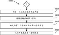
图26是根据本发明实施例的通过利用第一目标投射器投射第一图案来将第一信息传送至坐标测量装置的用户的方法中的步骤的流程图;26 is a flowchart of steps in a method of communicating first information to a user of a coordinate measuring device by projecting a first pattern with a first target projector in accordance with an embodiment of the present invention;
图27是图26中的标记C之后的方法中的步骤的流程图;Figure 27 is a flowchart of the steps in the method following label C in Figure 26;
图28是图26中的标记C之后的方法中的步骤的流程图;Figure 28 is a flowchart of the steps in the method following label C in Figure 26;
图29是图26中的标记C之后的方法中的步骤的流程图;Figure 29 is a flowchart of the steps in the method following label C in Figure 26;
图30是图26中的标记C之后的方法中的步骤的流程图;Figure 30 is a flowchart of the steps in the method following label C in Figure 26;
图31是根据本发明实施例的利用坐标测量装置和目标扫描仪来测量对象表面上的多个表面集的方法中的步骤的流程图;以及31 is a flowchart of steps in a method of measuring a plurality of surface sets on a surface of an object using a coordinate measuring device and a target scanner, according to an embodiment of the invention; and
图32是根据本发明实施例的利用坐标测量装置和目标扫描仪来测量对象对象表面上的多个表面集的方法中的步骤的流程图。32 is a flowchart of steps in a method of measuring a plurality of surface sets on a surface of an object using a coordinate measuring device and a target scanner, according to an embodiment of the invention.
具体实施方式Detailed ways
图1示出的示例性激光追踪器系统5包括激光追踪器10、回射器目标26、可选辅助单元处理器50和可选辅助计算机60。激光追踪器10的示例性万向光束转向机构12包括安装在方位基座16上并且绕方位轴20转动的天顶滑架14。有效载荷15安装在天顶滑架14上并且绕天顶轴18转动。在追踪器10内部,天顶轴18和方位轴20在通常作为距离测量的原点的万向点22处垂直相交。激光束46实际上穿过万向点22并且指向成与天顶轴18垂直。换句话说,激光束46存在于与天顶轴18大致垂直并且穿过方位轴20的平面内。输出激光束46由于有效载荷15绕天顶轴18的转动以及天顶滑架14绕方位轴20的转动而指向期望方向。将追踪器内部的天顶角编码器附接至与天顶轴18对准的天顶机械轴。将追踪器内部的方位角编码器附接至与方位轴20对准的方位机械轴。天顶角编码器和方位角编码器以相对较高的精度测量转动的天顶角和方位角。输出激光束46传播至例如可能是如上所述的球形安装的回射器(SMR)的回射器目标26。通过测量万向点22和回射器26之间的径向距离、绕天顶轴18的转动角和绕方位轴20的转动角,在追踪器的球面坐标系中找到回射器26的位置。The exemplary
如以下所述,输出激光束46可以包括一个或多个激光波长。为了清楚和简便,在以下论述中假定图1所示的这种转向机构。然而,其它类型的转向机构是可以的。例如,能够使激光束从绕方位轴和天顶轴转动的镜反射。无论转向机构的类型如何,均可应用本文描述的技术。As described below,
在激光追踪器上可以包括磁槽17以针对例如1.5、7/8和1/2英寸的SMR的不同大小的SMR将激光追踪器重置为“初始”位置。可以使用追踪器上回射器19将追踪器重置为参考距离。另外,如美国专利No.7,327,446(其内容通过引用并入于此)所述,可以将从图1不可见的追踪器上镜与追踪器上回射器相结合使用以使得能够进行自补偿。Magnetic slots 17 may be included on the laser tracker to reset the laser tracker to a "home" position for different sized SMRs such as 1.5, 7/8 and 1/2 inch SMRs. The tracker can be reset to a reference distance using the
图2示出示例性激光追踪器系统7,其中,除了以六DOF探测器1000替换回射器目标26以外,激光追踪器系统7与图1的激光追踪器系统5相同。在图1中,可以使用其它类型的回射器目标。例如,有时使用作为光会聚至玻璃结构的反射后表面上的小光斑的玻璃回射器的猫眼回射器。FIG. 2 shows an exemplary
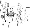
图3是示出激光追踪器实施例中的光学和电气元件的框图。图3示出如下激光追踪器的元件:该激光追踪器发出两个波长的光并且用于追踪,其中,第一波长用于ADM,第二波长用于可见指示器。可见指示器使得用户能够看见追踪器所发出的激光束光斑的位置。使用自由空间分束器来组合这两个不同波长。电光(EO)系统100包括可见光源110、隔离器115、可选第一光纤发射器170、可选干涉仪(IFM)120、扩束器140、第一分束器145、位置检测器组件150、第二分束器155、ADM160和第二光纤发射器170。Figure 3 is a block diagram showing the optical and electrical components in an embodiment of a laser tracker. Figure 3 shows elements of a laser tracker that emits two wavelengths of light and is used for tracking, where the first wavelength is used for the ADM and the second wavelength is used for the visible indicator. The visible indicator enables the user to see the location of the laser beam spot emitted by the tracker. The two different wavelengths are combined using a free space beam splitter. Electro-optic (EO)
可见光源110可以是激光器、超发光二极管或其它发光装置。隔离器115可以是Faraday隔离器、衰减器或能够减少反射回至光源的光的其它装置。可选IFM可以被配置为多种方式。作为可能实现的具体示例,IFM可以包括分束器122、回射器126、四分之一波板124、130和相位分析器128。可见光源110可以将光发射到自由空间,然后该光经过隔离器115和可选IFM120在自由空间内传播。可选地,隔离器115可以经由光纤线缆耦接至可见光源110。在这种情况下,如以下参考图5所论述的,来自隔离器的光可以经过第一光发射器170发射到自由空间内。Visible
可以使用各种透镜结构来设置扩束器140,但在图4A、4B中示出两种常用的现有技术结构。图4A示出基于使用负透镜141A和正透镜142A的结构140A。入射到负透镜141A上的准直光束220A从正透镜142A出射为较大的准直光束230A。图4B示出基于使用两个正透镜141B、142B的结构140B。入射到第一正透镜141B上的准直光束220B从第二正透镜142B出射为较大的准直光束230B。在从扩束器140离开的光中,少量光在从追踪器出来的路上从分束器145、155反射并且丢失。穿过分束器155的那部分光与来自ADM160的光相组合以形成离开激光追踪器并且传播至回射器90的复合光束188。The
在实施例中,ADM160包括光源162、ADM电子器件164、光纤网络166、互连电缆165和互连光纤168、169、184、186。ADM电子器件将电气调制和偏置电压发送至光源162,其中该光源162例如可以是以约1550nm的波长工作的分布式反馈激光器。在实施例中,光纤网络166可以是图8A所示的现有技术的光纤网络420A。在本实施例中,来自图3中的光源162的光经由与图8A中的光纤432等同的光纤184传播。In an embodiment,
图8A的光纤网络包括第一光纤耦合器430、第二光纤耦合器436和低传输反射器435、440。光经由第一光纤耦合器430传播并且分裂成以下两个路径,其中第一路径经由光纤433至第二光纤耦合器436,第二路径经过光纤422和光纤长度均衡器423。光纤长度均衡器423连接至图3的光纤长度168,其中该光纤长度168传播至ADM电子器件164的参考通道。光纤长度均衡器423的目标是使光在参考通道内所经过的光纤的长度与光在测量通道内所经过的光纤的长度一致。这种方式的光纤长度一致减少了因环境温度的变化所引起的ADM误差。由于光纤的有效光路长度与光纤的平均折射率乘以光纤长度相等,因此可能产生这样的误差。由于光纤的折射率依赖于光纤的温度,因此光纤的温度变化导致测量通道和参考通道的有效光路长度出现变化。在测量通道内的光纤的有效光路长度相对于参考通道内的光纤的有效光路长度改变的情况下,即使回射器目标90保持静止,该结果也将在回射器目标90的位置发生明显偏移。为了避免该问题,采取两个步骤。首先,使参考通道内的光纤的长度与测量通道内的光纤的长度尽可能匹配。其次,并排铺设测量光纤和参考光纤以达到能够确保两个通道内的光纤经历近乎相同的温度变化的程度。The fiber optic network of FIG. 8A includes a first
光经由第二光纤光耦合器436传播并且分裂成以下两个路径,其中,第一路径至低反射光纤终端440,第二路径至光纤438,其中光从光纤438传播至图3的光纤186。光穿过光纤186而传播至第二光纤发射器170。The light propagates through the second
在实施例中,在现有技术的图5中示出光纤发射器170。来自图3中的光纤186的光入射到图5中的光纤172。光纤发射器170包括光纤172、箍174和透镜176。光纤172附接至箍174,其中箍174稳定地附接至激光追踪器10内的结构。如果需要,可以将光纤的端部打磨成角以减少背向反射。根据所使用的光的波长和光纤的特定类型,光250从可以是直径为4~12微米的单模光纤的光纤的纤芯出射。光250分叉成一定角并且与透镜176相交,其中透镜176使光250平行。参考专利‘758中的图3说明了经由ADM系统中的单模光纤来发射和接收光信号的方法。In an embodiment, a
参考图3,分束器155可以是发射不同于所反射的波长的两色分束器。在实施例中,来自ADM160的光从两色分束器155反射并且与透过两色分束器155的来自可见激光110的光合并。复合光束188从激光追踪器传播出来至回射器90作为第一光束,其中回射器90返回光的一部分作为第二光束。第二光束部分以ADM波长从两色分束器155反射并且返回至第二光纤发射器170,其中第二光纤发射器170将光返回耦接至光纤186。Referring to FIG. 3, the
在实施例中,光纤186与图8A中的光纤438相对应。返回光自光纤438穿过第二光纤耦合器436传播并且分裂成两个路径。在本实施例中,第一路径通往光纤424,光纤424与通往图3中的ADM电子器件164的测量通道的光纤169相对应。第二路径通往光纤433,然后通往第一光纤耦合器430。离开第一光纤耦合器430的光分裂成两个路径,第一路径至光纤432,第二路径至低反射终端435。在实施例中,光纤432与通往图3中的光源162的光纤184相对应。在大多情况中,光源162包含使从光纤432进入光源的光量最小化的内置Faraday隔离器。在相反方向上反馈到激光内的过多的光可能会使激光不稳定。In an embodiment,
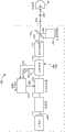
来自光纤网络166的光经由光纤168、169入射到ADM电子器件164。在图7中示出现有技术的ADM电子器件的实施例。图3中的光纤168与图7中的光纤3232相对应,并且图3中的光纤169与图7中的光纤3230相对应。现在参考图7,ADM电子器件3300包括频率参考3302、合成器3304、测量检测器3306、参考检测器3308、测量混合器3310、参考混合器3312、调节电子器件3314、3316、3318、3320、N分预分频器3324和模数转换器(ADC)3322。例如可以是恒温控制的晶体振荡器(OCXO)的频率参考将例如可以为10MHz的参考频率fREF发送至合成器,其中合成器产生两种电信号:频率为fRF的一个信号和频率为fLO的两个信号。信号fRF进入与图3中的光源162相对应的光源3102。频率为fLO的两个信号进入测量混合器3310和参考混合器3312。来自图3中的光纤168,169的光分别出现在图7中的光纤3232,3230上,并且分别入射到参考通道和测量通道。参考检测器3308和测量检测器3306将光信号转换成电信号。这些信号分别由电气组件3316、3314进行调节,并且分别被发送至混合器3312、3310。这些混合器产生与fLO–fRF的绝对值相等的频率fIF。信号fRF可以是例如2GHz的相对高的频率,而信号fIF可以是例如10kHz的相对较低的频率。Light from
将参考频率fREF发送至预分频器3324,其中预分频器3324将频率除以整数值。例如,可以将10MHz的频率除以40以获得250kHz的输出频率。在该示例中,以250kHz的速率对进入ADC3322的10kHz信号进行采样,由此产生25个样本/每周期。将来自ADC3322的信号发送至数据处理器3400,其中数据处理器3400例如可以是位于图3的ADM电子器件164中的一个或多个数字信号处理器(DSP)单元。The reference frequency fREF is sent to
用于提取距离的方法基于针对参考通道和测量通道的ADC信号的相位的计算。在Bridges等人的美国专利No.7,701,559(‘559)中详细描述了该方法,其内容通过引用并入于此。计算包括使用专利‘559的等式(1)~(8)。另外,在ADM首次开始测量回射器时,将合成器所生成的频率改变若干次(例如,3次),并且在各情况下计算可能的ADM距离。通过针对所选择的各频率比较可能的ADM距离,消除了ADM测量时的不确定。专利‘559的等式(1)~(8)连同关于专利‘559的图5所述的同步方法和专利‘559所述的Kalman滤波器方法使得ADM能够测量移动目标。在其它实施例中,可以使用用于获得绝对距离测量的其它方法,例如通过使用脉冲飞行时间(time-of-flight)而不是相位差来获得绝对距离测量的方法。The method for extracting the distance is based on the calculation of the phases of the ADC signals for the reference channel and the measurement channel. This method is described in detail in Bridges et al., U.S. Patent No. 7,701,559 ('559), the contents of which are incorporated herein by reference. The calculation involves using equations (1)-(8) of the '559 patent. In addition, when the ADM first starts measuring the retroreflector, the frequency generated by the synthesizer is changed several times (eg, 3 times) and the possible ADM distance is calculated in each case. By comparing the possible ADM distances for each selected frequency, uncertainties in ADM measurements are eliminated. Equations (1)-(8) of the '559 patent, together with the synchronization method described in relation to Figure 5 of the '559 patent and the Kalman filter method described in the '559 patent, enable the ADM to measure moving targets. In other embodiments, other methods for obtaining absolute distance measurements may be used, such as by using pulse time-of-flight rather than phase differences to obtain absolute distance measurements.
返回光束190的穿过分束器155的部分到达分束器145,其中分束器145将该光的一部分发送至扩束器140并且将该光的另一部分发送至位置检测器组件150。从激光追踪器10或EO系统100出射的光可被看作第一光束,并且从回射器90或26反射的光的一部分可被看作第二光束。反射光束的部分被发送至EO系统100的不同功能元件。例如,可以将第一部分发送至诸如图3中的ADM160的测距仪。可以将第二部分发送至位置检测器组件150。在一些情况下,可以将第三部分发送至诸如可选干涉仪120的其它功能单元。理解以下很重要:在图3的示例中,尽管第二光束的第一部分和第二部分在从分束器155和145反射之后分别被发送至测距仪和位置检测器,但可以使光透过而不是反射到测距仪或位置检测器上。The portion of
在图6A~6D中示出现有技术的位置检测器组件150A~150D的四个示例。图6A示出最简单的实现方式,其中位置检测器组件包括安装在用于从电子箱350获得电力并且将信号返回至电子箱350的电路板152上的位置传感器151,其可以表示在激光追踪器10、辅助单元50或外部计算机60内的任意位置处的电子处理能力。图6B包括用于阻断不期望的光波长到达位置传感器151的光学滤波器154。例如,还可以通过利用适当膜涂覆分束器145或位置传感器151的表面来阻断不期望的光波长。图6C包括用于减小光束的大小的透镜153。图6D包括光学滤波器154和透镜153这两者。Four examples of prior art
图6E示出根据本发明的一个实施例的包括光学调节器149E的位置检测器组件。光学调节器包括透镜153并且还可以包含可选的波长滤波器154。另外,光学调节器包括扩散器156和空间滤波器157中的至少一个。如以上所述,普遍类型的回射器为立方隅角回射器。一种类型的立方隅角回射器由三个镜构成,其中,每个镜与其它两个镜以直角结合。这三个镜相结合的截交线可以具有光不会被完全反射回至追踪器的有限厚度。有限厚度的线随着它们传播而衍射,使得这些线在到达位置检测器时可以不出现在位置检测器上的完全相同位置处。然而,衍射光图案通常将不满足完全对称。结果,照射位置检测器151的光例如在衍射线附近可能光学功率(热点)下降或上升。由于来自回射器的光的均一性在各回射器之间可能改变,并且还由于位置检测器上的光的分布也可能随着回射器转动或倾斜而改变,因此包括扩散器156以提高照射位置检测器151的光的平滑度可能是有利的。可能会争辩,由于理想位置检测器应当对应于质心并且理想扩散器应当对称地扩散光斑,因此不会对位置检测器所给出的结果位置产生影响。然而,实际上,观察到扩散器改进了位置检测器组件的性能,这可能是因为位置检测器151和透镜153的非线性(不完善)的影响。由玻璃制成的立方隅角回射器还可能在位置检测器151处产生非均匀的光斑。如根据共同受让人的于2012年2月10日提交的美国专利申请No.13/370,339和于2012年2月29日提交的美国专利申请No.13/407,983(这两个申请通过引用并入于此)可以更加清楚地理解,位置检测器处的光斑的变化相对于从六DOF目标中的立方隅角反射的光特别明显。在实施例中,扩散器156是全息扩散器。全息扩散器在指定扩散角上提供受控的同质光。在其它实施例中,使用诸如毛玻璃或“乳色玻璃”扩散器的其它类型的扩散器。Figure 6E shows a position detector assembly including an
位置检测器组件150E的空间滤波器157的目标是阻断例如可能作为光学表面的不期望的反射结果的重影光束照射位置检测器151。空间滤波器包括具有孔径的板157。通过将空间滤波器157布置为距透镜的距离近似等于透镜的焦距,返回光243E在接近其最窄时(即光束的腰部处)穿过空间滤波器。例如,作为光学元件的反射结果而以不同角传播的光束偏离孔径照射空间滤波器并且被阻止达到位置检测器151。在图6E中示出如下示例:不期望的重影光束244E从分束器145的表面反射并且传播至空间滤波器157,在空间滤波器157处,该重影光束被阻断。在不存在空间滤波器的情况下,重影光束244E将与位置检测器151相交,由此导致不正确地确定光束243E在位置检测器151上的位置。在重影光束位于距光的主要斑点相对大的距离处的情况下,即使微弱的重影光束也可能极大地改变位置检测器151上质心的位置。The goal of the
这里论述的这种回射器、立方隅角或猫眼反射器具有例如反射沿与入射光线平行的方向入射到回射器的光射线的性质。另外,入射光线和反射光线关于回射器的对称点对称配置。例如,在露天的立方隅角回射器中,回射器的对称点是立方隅角的顶点。在玻璃立方隅角回射器中,对称点也是顶点,但这种情况下必须考虑玻璃空气界面处的光的弯曲。在衍射率为2.0的猫眼回射器中,对称点也是球体中心。在由对称地位于共同面上的两个玻璃半球体制成的猫眼回射器中,对称点是存在于该平面上并且处于各半球体的球形中心的点。对于激光追踪器通常使用的回射器类型,主点是将回射器返回至追踪器的光偏向相对于入射激光束的顶点的另一侧。Such retroreflectors, cube corners or cat's eye reflectors as discussed herein have, for example, the property of reflecting light rays incident on the retroreflector in a direction parallel to the incident light rays. In addition, incident rays and reflected rays are arranged symmetrically about the symmetry point of the retroreflector. For example, in an open air cube corner retroreflector, the point of symmetry of the retroreflector is the apex of the cube corner. In glass cube corner retroreflectors, the point of symmetry is also the vertex, but in this case the bending of light at the glass-air interface must be considered. In a cat's eye retroreflector with a diffraction index of 2.0, the point of symmetry is also the center of the sphere. In a cat's eye retroreflector made of two glass hemispheres symmetrically located on a common plane, the point of symmetry is the point that exists on this plane and is at the spherical center of each hemisphere. For the type of retroreflector typically used with laser trackers, the principal point is the direction of light returning to the tracker from the retroreflector to the other side of the apex relative to the incident laser beam.
图3中的回射器90的该行为是利用激光追踪器来追踪回射器的基础。位置传感器在其表面上具有理想折回点。该理想折回点是发送至回射器的对称点(例如,SMR中的立方隅角回射器的顶点)的激光束将返回的点。通常,折回点接近位置传感器的中心。在将激光束发送至回射器的一侧的情况下,该激光束在另一侧上反射回来并且呈现为离开位置传感器上的折回点。通过注意位置传感器上的返回光束的位置,激光追踪器10的控制系统可以使电机将光束朝向回射器的对称点移动。This behavior of the
在回射器以恒定速度相对于追踪器横向移动的情况下,回射器处的光束(在解决了瞬态之后)在距回射器的对称点固定偏移距离处照射回射器。激光追踪器基于从控制测量所获得的缩放因数和从位置传感器上的光束到理想折回点的距离进行校正,以补偿回射器处的该偏移距离。With the retroreflector moving laterally with respect to the tracker at a constant velocity, the beam at the retroreflector (after resolving the transient) illuminates the retroreflector at a fixed offset distance from the retroreflector's point of symmetry. The laser tracker is corrected based on the scaling factor obtained from the control measurements and the distance from the beam on the position sensor to the ideal return point to compensate for this offset distance at the retroreflector.
如以上所述,位置检测器进行两个主要功能,这两个功能使得能够追踪并校正测量以补偿回射器的移动。位置检测器内的位置传感器可以是能够测量位置的任意类型的装置。例如,位置传感器可以是位置感测检测器或光敏阵列。位置感测检测器例如可以是横向效应检测器或象限检测器。光敏阵列例如可以是CMOS或CCD阵列。As mentioned above, the position detector performs two main functions which enable tracking and correcting measurements to compensate for retroreflector movement. The position sensor within the position detector may be any type of device capable of measuring position. For example, the position sensor may be a position sensing detector or a photosensitive array. The position sensing detectors may be, for example, lateral effect detectors or quadrant detectors. The photosensitive array can be, for example, a CMOS or CCD array.
在实施例中,没有从分束器145反射的返回光穿过扩束器140,从而变得较小。在另一实施例中,颠倒位置检测器的位置和测距仪的位置,以使得分束器145所反射的光传播至测距仪并且透过分束器的光传播至位置检测器。In an embodiment, return light not reflected from the
光继续穿过可选IFM,穿过隔离器并且入射到可见光源110。在该阶段,光学功率应足够小以使得其不会使可见光源110不稳定。The light continues through the optional IFM, through the isolator and is incident on the visible
在实施例中,经由图5中的光束发射器170发射来自可见光源110的光。光纤发射器可以附接至光源110的输出或隔离器115的光纤输出。In an embodiment, light from visible
在实施例中,图3的光纤网络166可以是图8的现有技术的光纤网络420B。这里,图3的光纤184、186、168、169与图8B的光纤443、444、424、422相对应。除了图8B的光纤网络具有单个光纤耦合器而非两个光纤耦合器之外,图8B的光纤网络与图8A的光纤网络相同。图8B相对于图8A的优点是简洁;然而,图8B更可能使不期望的光学背向反射进入光纤422和424。In an embodiment,
在实施例中,图3的光纤网络166是图8C的光纤网络420C。这里,图3的光纤184、186、168、169与图8C的光纤447、455、423、424相对应。光纤网络420C包括第一光纤耦合器445和第二光纤耦合器451。第一光纤耦合器445是具有两个输入端口和两个输出端口的2×2耦合器。这种耦合器通常通过邻近地配置两个光纤纤芯然后在被加热时拉制这些光纤制成。这样,光纤之间的倏逝波耦合(evanescent coupling)可以将光的期望部分分离到相邻光纤。第二光纤耦合器451是所谓的环行器类型。第二光纤耦合器451包括三个端口,每个端口具有仅在指定方向上发送或接收光的能力。例如,光纤448上的光入射到端口453并且如由箭头所示朝向端口454传播。在端口454处,光可以被传输至光纤455。同样,在端口455上传播的光可以入射到端口454并且沿箭头方向传播至端口456,其中在端口456处,一些光可以被传输至光纤424。在仅需要三个端口的情况下,环行器451可能经受比2×2耦合器小的光学功率损耗。另一方面,环行器451可能比2×2耦合器更贵,并且可能经历在一些情形下可能成为问题的偏振模式分散。In an embodiment,
图9和10分别示出Bridges等人的美国公开专利申请No.2010/0128259的图2和3中所述的现有技术的激光追踪器2100的分解图和截面图,其中通过引用并入该申请。方位组件2110包括柱状壳体2112、方位编码器组件2120、下方位轴承2114A和上方位轴承2114B、方位电机组件2125、方位滑环组件2130和方位电路板2135。9 and 10 show an exploded and cross-sectional view, respectively, of a prior
方位编码器组件2120的目标是准确地测量轭2142相对于柱状壳体2112的转动角。方位编码器组件2120包括编码器盘2121和读取头组件2122。编码器盘2121附接至轭壳体2142的轴,并且读取头组件2122附接至支柱组件2110。读取头组件2122包括其上紧固有一个或多个读取头的电路板。发送自读取头的激光从编码器盘2121上的细光栅线反射出来。对编码器读取头上的检测器拾取到的反射光进行处理以求出编码器盘相对于固定读取头转动的角。The goal of the
方位电机组件2125包括方位电机转子2126和方位电机定子2127。方位电机转子包括直接附接至轭壳体2142的轴的永磁体。方位电机定子2127包括产生规定的磁场的场绕组。该磁场与方位电机定子2126的磁体相互作用以产生期望的转动动作。方位电机定子2127附接至柱状架2112。The
方位电路板2135表示用于提供诸如编码器和电机的方位组件所需的电气功能的一个或多个电路板。方位滑环组件2130包括外部部件2131和内部部件2132。在实施例中,线束2138从辅助单元处理器50露出。线束2138可以将电力传递至追踪器或者将信号传输至追踪器或从追踪器传输信号。线束2138中的一些布线可以指向电路板上的连接器。在图10所示的示例中,将线布到方位电路板2135、编码器读取头组件2122和方位电机组件2125。其它线布到达滑环组件2130的内部部件2132。内部部件2132附接至柱状组件2110并且因而保持静止。外部部件2131附接至轭组件2140并且因而相对于内部部件2132转动。滑环组件2130被设计成随着外部部件2131相对于内部部件2132转动而允许低阻抗电气接触。
天顶部件2140包括轭壳体2142、天顶编码器组件2150、左天顶轴承2144A和右天顶轴承2144B、天顶电机组件2155、天顶滑环组件2160和天顶电路板2165。
天顶编码器组件2150的目标是准确地测量有效载荷框架2172相对于轭壳体2142的转动角。天顶编码器组件2150包括天顶编码器盘2151和天顶读取头组件2152。编码器盘2151附接至有效载荷壳体2142并且读取头组件2152附接至轭壳体2142。天顶读取头组件2152包括其上紧固有一个或多个读取头的电路板。发送自读取头的激光从编码器盘2151上的细光栅线反射出来。对编码器读取头上的检测器所拾取的反射光进行处理,以求出编码器盘相对于固定读取头转动的角。The goal of the
天顶电机组件2155包括方位电机转子2156和方位电机定子2157。天顶电机转子2156包括直接附接至有效载荷框架2172的轴的永磁体。天顶电机定子2157包括用于生成规定的磁场的场绕组。该磁场与转子磁体相互作用以产生期望的转动动作。天顶电机定子2157附接至轭框架2142。
天顶电路板2165表示用于提供诸如编码器和电机的天顶部件所需的电气功能的一个或多个电路板。天顶滑环组件2160包括外部部件2161和内部部件2162。线束2168从方位外部滑环2131露出并且可以输送电力或信号。线束2168中的一些布线可以指向电路板上的连接器。在图10所示的例子中,将线布到天顶电路板2165、天顶电机组件2150和编码器读取头组件2152。将其它线布到滑环组件2160的内部部件2162。内部部件2162附接至轭框架2142并且因而仅以方位角而不以天顶角转动。外部部件2161附接至有效载荷框架2172并且因而以天顶角和方位角这两者转动。滑环组件2160被设计成随着外部部件2161相对于内部部件2162转动而允许低阻抗电气接触。有效载荷组件2170包括主光学组件2180和副光学组件2190。
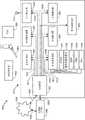
图11是示出维度测量电子处理系统1500的框图,其中,维度测量电子处理系统1500包括激光追踪器电子处理系统1510、外围元件1582、1584、1586的处理系统、计算机1590和这里表示为云的其它网络部件1600。示例性的激光追踪器电子处理系统1510包括主处理器1520、有效载荷功能电子器件1530、方位编码器电子器件1540、天顶编码器电子器件1550、显示器和用户界面(UI)电子器件1560、可移除存储硬件1565、射频识别(RFID)电子器件和天线1572。有效载荷功能电子器件1530包括多个子功能,包含六DOF电子器件1531、摄像装置电子器件1532、ADM电子器件1533、位置检测器(PSD)电子器件1534和水平电子器件1535。大多数子功能具有例如可以是数字信号处理器(DSP)或现场可编程门阵列(FPGA)的至少一个处理器单元。电子单元1530、1540和1550由于它们在激光追踪器内的位置而单独示出。在实施例中,有效载荷功能1530位于图9、10的有效载荷2170内,而方位编码器电子器件1540位于方位组件2110内并且天顶编码器电子器件1550位于天顶组件2140内。11 is a block diagram illustrating a dimensional measurement
可以具有多种外围装置,但这里示出三个这种装置:温度传感器1582、六DOF探测器1584和例如可以是智能电话的个人数字助理1586。激光追踪器可以通过各种方式与外围装置通信,包括:通过诸如摄像装置的视觉系统和通过激光追踪器向诸如六DOF探测器1584的协作目标的距离读取和角读取来经由天线1572进行无线通信。外围装置可以包含处理器。六DOF辅助设备可以包括六DOF探测系统、六DOF扫描仪、六DOF投射器、六DOF传感器和六DOF指示器。这些六DOF装置内的处理器可以结合激光追踪器内的处理装置以及外部计算机和云处理资源来使用。通常,在使用术语激光追踪器处理器或测量装置处理器时,这意味着包括可能的外部计算机和云支持。There may be a variety of peripheral devices, but three such devices are shown here: a
在实施例中,单独的通信总线从主处理器1520到达各电子单元1530、1540、1550、1560、1565和1570。每个通信线例如可以具有三个串行线,这三个串行线包括数据线、时钟线和帧线。帧线表示电子单元是否应关注时钟线。在帧线表示应注意的情况下,电子单元在各时钟信号读取数据线的当前值。时钟信号例如可能对应于时钟脉冲的上升沿。在实施例中,以包的形式经由数据线来传输信息。在实施例中,每个包包括地址、数字值、数据消息和校验和。该地址表示数字消息要指向电子单元内的何处。该位置例如可以与电子单元内的处理器子例程相对应。数字值表示数据消息的长度。数据消息包含电子单元要执行的数据或指令。校验和是用于使经由通信线传输误差的机会最小的数字值。In an embodiment, a separate communication bus goes from the
在实施例中,主处理器1520将信息包经由总线1610发送至有效载荷功能电子器件1530,经由总线1611发送至方位编码器电子器件1540,经由总线1612发送至天顶编码器电子器件1550,经由总线1613发送至显示器和UI电子器件1560,经由总线1614发送至可移除存储硬件1565,并且经由总线1616发送至RFID和无线电子器件1570。In an embodiment, the
在实施例中,主处理器1520还将同步脉冲经由同步总线1630同时发送至各电子单元。同步脉冲提供使激光追踪器的测量功能所收集到的值同步的方式。例如,方位编码器电子器件1540和天顶电子器件1550一旦接收到同步脉冲,就锁存它们的编码器值。类似地,有效载荷功能电子器件1530锁存由有效载荷内包含的电子器件所收集的数据。在给出同步脉冲时,六DOF、ADM和位置检测器全部锁存数据。在多数情况下,摄像装置和倾斜仪以比同步脉冲速率慢的速率收集数据但可以以同步脉冲周期的多倍锁存数据。In an embodiment, the
方位编码器电子器件1540和天顶编码器电子器件1550彼此分开并且经由图9、10所示的滑环2130、2160与有效载荷电子器件1530分开。这就是将总线1610、1611和1612描述为图11中的单独总线的原因。The
激光追踪器电子处理系统1510可以与外部计算机1590进行通信,或者可以提供激光追踪器内的计算、显示和UI功能。激光追踪器经由例如可以是以太网线或无线连接的通信链路1606与计算机1590进行通信。激光追踪器还可以经由可以包括诸如以太网线缆的一个或多个电缆以及一个或多个无线连接的通信链路1602来与以云为代表的其它元件1600进行通信。元件1600的示例是可以利用激光追踪器来重新定位的例如关节臂CMM的其它三维测试仪器。计算机1590和元件1600之间的通信链路1604可以是有线(例如,以太网)或无线的。坐在远程计算机1590处的操作员可以经由以太网或无线线路连接至以云1600为代表的因特网,而云1600经由以太网或无线线路连接至主处理器1520。这样,用户可以对远程激光追踪器的动作进行控制。Laser tracker
如今激光追踪器针对ADM使用一个可见波长(通常为红色)和一个红外波长。红色波长可以由适合用在干涉仪中并且还用来提供红色指示光束的频率稳定的氦氖(HeNe)激光是来提供。可选地,红色波长可以由仅用作指示光束的二极管激光来提供。使用两个光源的缺点在于额外光源、分束器、隔离器和其它部件所需的额外空间和附加成本。使用两个光源的另一缺点是难以使这两个光束沿着光束传播的整个路径完全对准。这可能会导致各种问题,包括无法从以不同波长工作的不同子系统同时获得良好性能。在图12A的光电系统500中示出使用单个光源并由此消除这些缺点的系统。Today's laser trackers use a visible wavelength (usually red) and an infrared wavelength for the ADM. The red wavelength may be provided by a frequency stabilized helium-neon (HeNe) laser suitable for use in an interferometer and also used to provide a red indicator beam. Alternatively, the red wavelength may be provided by a diode laser used only as an indicator beam. The disadvantage of using two light sources is the extra space and additional cost required for the extra light source, beam splitter, isolator and other components. Another disadvantage of using two light sources is that it is difficult to perfectly align the two beams along the entire path the beams travel. This can lead to various problems, including not being able to simultaneously get good performance from different subsystems operating at different wavelengths. A system that uses a single light source and thereby eliminates these disadvantages is shown in the
图12A包括可见光源110、隔离器115、光纤网络420、ADM电子器件530、光纤发射器170、分束器145和位置检测器150。可见光源110例如可以是红色或绿色二极管激光或垂直腔面发射激光(VCSEL)。隔离器可以是Faraday隔离器、衰减器或能够充分减少反馈至光源的光量的任何其它装置。来自隔离器115的光传播至光纤网络420,在实施例中,光纤网络420为图8A的光纤网络420A。12A includes visible
图12B示出光电系统400的实施例,其中,在光电系统400中,使用单波长的光但通过光的电光调制而不是光源的直接调制来实现调制。光电系统400包括可见光源110、隔离器115、电光调制器410、ADM电子器件475、光纤网络420、光纤发射器170、分束器145和位置检测器150。可见光源110例如可以是红色或绿色激光二极管。经由例如可以是Faraday隔离器或衰减器的隔离器115来发送激光。可以在隔离器115的输入端口和输出端口进行光纤耦合。隔离器115将光发送至电光调制器410,其中,电光调制器410将光调制为选择频率,选择频率可以根据需要高达10GHz或更高。来自ADM电子器件475的电信号476驱动电光调制器410内的调制。来自电光调制器410的调制光传播至光纤网络420,其可以是以上所述的光纤网络420A、420B、420C或420D。光的一些部分经由光纤422传播至ADM电子器件475内的参考通道。光的另一部分传播到追踪器外、从回射器90反射、返回至追踪器并且到达分束器145。少量的光从分束器反射并且传播至以上参考图6A~6F所述的位置检测器150。光的一部分穿过分束器145入射到光纤发射器170、经由光纤网络420入射到光纤424,并且入射到ADM电子器件475的测量通道。通常,为了比图12B的系统400省钱,可以制造图12A的系统500;然而,电光调制器410能够实现更高的调制频率,这在一些情形下是有利的。Figure 12B shows an embodiment of an
图13示出定位摄像装置系统950和光电系统900的实施例,其中,方位摄像装置910与3D激光追踪器的光电功能相结合来测量六自由度。光电系统900包括可见光源905、隔离器910、可选光电调制器410、ADM电子器件715、光纤网络420、光纤发射器170、分束器145、位置检测器150、分束器922和方位摄像装置910。来自可见光源的光在光纤980中发出并且经由输入端口和输出端口可以耦合有光纤的隔离器910传播。光可以经由利用来自ADM电子器件715的电信号716调制的电光调制器410传播。可选地,ADM电子器件715可以经由线缆717发送电信号以对可见光源905进行调制。入射到光纤网络的光的一部分经由光纤长度均衡器423和光纤422传播以入射到ADM电子器件715的参考通道。可以可选地将电信号469应用于光纤网络420以将开关信号提供至光纤网络420内的光纤开关。光的一部分从光纤网络传播至光纤发射器170,其中该光纤发射器170将光纤上的光作为光束982发送到自由空间内。少量的光从分束器145反射并且丢失。光的一部分穿过分束器145、穿过分束器922,并且传播到追踪器外而到达六自由度(DOF)装置4000。六DOF装置4000可以是探测器、扫描仪、投射器、传感器或其它装置。Figure 13 shows an embodiment of a
在其返回路径上,来自六DOF装置4000的光入射到光电系统900并且到达分束器922。光的一部分从分束器922反射并且入射到方位摄像装置910。方位摄像装置910记录放置在回射器目标上的一些标记的位置。根据这些标记,求出六DOF探测器的方位角(即,三自由度)。以下说明本申请及专利‘758中的方位摄像装置的原理。分束器145处的光的一部分经由分束器传播并且通过光纤发射器170发射到光纤上。光传播至光纤网络420。该光的一部分传播至光纤424,其中该光从光纤424入射到ADM电子器件715的测量通道。On its return path, light from six
定位摄像装置系统950包括摄像装置960和一个或多个光源970。在图1中也示出该定位摄像装置系统,其中摄像装置为元件52并且光源是元件54。摄像装置包括透镜系统962、光敏阵列964和主体966。定位摄像装置系统950的一个用途是在工作体积中定位回射器目标。这通过使光源970闪光来进行,其中摄像装置将光源970拍摄作为光敏阵列964上的亮点。定位摄像装置系统950的第二个用途是基于反射器光点或LED在六DOF装置4000上的观察位置来建立六DOF装置4000的粗略方位。在激光追踪器上可存在两个或更多个定位摄像装置的情况下,可以使用三角测量原理来计算至工作体积中的每个回射器目标的方向。在单个定位摄像装置被定位成拍摄沿着激光追踪器的光轴反射的光的情况下,可以找到至每个回射器目标的方向。在单个摄像装置被定位为偏离激光追踪器的光轴的情况下,可以根据光敏阵列上的图像立即获得至回射器目标的近似方向。在这种情况下,可以通过使激光的机械轴朝向不止一个方向转动并且观察光敏阵列上的光点位置的变化来求出至目标的更精确方向。
图14示出与光电系统900和定位摄像装置系统950相结合使用的六DOF探测器200的实施例。参考图13说明了光电系统900和定位摄像装置系统950。在另一实施例中,以具有两个或更多个波长的光电系统替换光电系统900。六DOF探测器2000包括主体2014、回射器2010、探测器延伸组件2050、可选电缆2046、可选电池2044、接口部件2012、识别元件2049、致动器按钮2016、天线2048和电子电路板2042。回射器可以是具有中空纤芯或玻璃纤芯的立方隅角回射器。可以对回射器进行标记,以使得能够利用光电系统900内的方位摄像装置确定六DOF探测器2000的三个方位自由度。如专利‘758所述,这种标记的示例是回射器2010的三个平坦反射面之间的截交线的暗色化。探测器延伸组件2050包括探测器延伸2052和探测器前端2054。使探测器前端接触被测对象。尽管探测器前端2054独立于回射器2010,但六DOF激光追踪器能够在隐藏于来自激光追踪器的光束784的视线的点处确定探测器前端2054的三维坐标。这就是六DOF探测器有时被称为隐藏点探测器的原因。FIG. 14 shows an embodiment of a six DOF detector 200 used in conjunction with an
可以经由可选电缆2046或通过可选电池2044来提供电力。电子电源力向电子电路板2042提供电力。电子电路板2042向可以与激光追踪器或外部计算机进行通信的天线2048、以及向用户提供与激光追踪器或外部计算机进行通信的简便方式的致动器按钮2016提供电力。电子电路板2042还可以向LED、材料温度传感器(未示出)、空气温度传感器(未示出)、惯性传感器(未示出)或倾斜仪(未示出)提供电力。接口部件2012例如可以是光源(诸如LED)、小型回射器、反射材料的区域或参考标记。接口组件2012用于建立六DOF角的计算时所需的回射器2010的粗略方位。识别元件2049用于向激光追踪器提供六DOF探测器的参数或序列号。识别元件例如可以是条形码或RF识别标签。Power may be provided via an
可选地,激光追踪器可以将光束784提供至回射器2011。通过将光束784提供至多个回射器中的任一个,六DOF探测器2000可以在利用探测延伸组组件2050进行探测的同时朝向各种方向。Optionally, a laser tracker may provide
激光追踪器所测量的六自由度可被视为包括三个平移自由度和三个方位自由度。三个平移自由度可以包括径向距离测量、第一角测量和第二角测量。径向距离测量可以利用IFM或ADM来进行。第一角测量可以利用诸如方位角编码器的方位角测量装置来进行,并且第二角测量可以利用天顶角测量装置来进行。可选地,第一角测量装置可以是天顶角测量装置并且第二角测量装置可以是方位角测量装置。径向距离、第一角测量和第二角测量构成球体坐标系中的三个坐标,这三个坐标可以变换成Cartesian坐标系或其它坐标系中的三个坐标。The six degrees of freedom measured by the laser tracker can be regarded as including three translational degrees of freedom and three orientational degrees of freedom. The three translational degrees of freedom may include a radial distance measurement, a first angular measurement, and a second angular measurement. Radial distance measurements can be made using IFM or ADM. The first angular measurement may be made with an azimuth measuring device, such as an azimuth encoder, and the second angular measurement may be made with a zenith measuring device. Alternatively, the first angular measuring device may be a zenith measuring device and the second angular measuring device may be an azimuth measuring device. The radial distance, the first angular measure and the second angular measure constitute three coordinates in a spherical coordinate system, which can be transformed into three coordinates in a Cartesian coordinate system or other coordinate systems.
如以上和专利‘758所述,可以使用图案化立方隅角来确定三个方位自由度。可选地,可以使用确定三个方位自由度的其它方法。三个平移自由度和三个方位自由度完全确定了六DOF探测器2000在空间内的位置和方位。注意,由于可能具有六自由度不独立由此六自由度不足以完全限定空间内的位置和方位的系统,因此这是针对这里所述的系统的情况。术语“平移集”是追踪器参考坐标系(或装置参考坐标系)中的六DOF附件(诸如六DOF探测器)的三个平移自由度的简化符号。术语“方位集”是追踪器参考坐标系中的六DOF附件的三个方位自由度的简化符号。术语“表面集”是装置参考坐标系中的对象面上的点的三维坐标的简化符号。As described above and in the '758 patent, patterned cube corners can be used to determine three azimuth degrees of freedom. Alternatively, other methods of determining the three orientation degrees of freedom can be used. Three translation degrees of freedom and three orientation degrees of freedom fully determine the position and orientation of the six
图15示出与光电系统900和定位摄像装置系统950结合使用的六DOF扫描仪2500的实施例。六DOF扫描仪2500还可被称为“目标扫描仪”。参考图13讨论了光电系统900和定位摄像装置系统950。在另一实施例中,以使用两个或更多个波长的光的光电系统代替光电系统900。六DOF扫描仪2500包括主体2514、一个或多个回射器2510、2511、扫描仪摄像装置2530、扫描仪光投射器2520、可选电缆2546、可选电池2444、接口部件2512、识别元件2549、致动器按钮2516、天线2548和电子电路板2542。图15中的回射器2510、可选电缆2546、可选电池2544、接口部件2512、识别元件2549、致动器按钮2516、天线2548和电子电路板2542分别对应于图14中的回射器2010、可选电缆2046、可选电池2044、接口部件2012、识别元件2049、致动器按钮2016、天线2048和电子电路板2042。对于这些对应元件的说明与参考图14所述的原件的说明相同。并且,扫描投射器2520和扫描摄像装置2530用于测量工件2528的三维坐标。摄像装置2530包括摄像装置透镜系统2532和光敏阵列2534。光敏阵列2534例如可以是CCD或CMOS阵列。扫描投射器2520包括投射器透镜系统2523和光的源图案2524。该光的源图案可以发出光点、光线或光的结构(二维)图案。在扫描仪光源发出光点的情况下,例如可以通过移动镜来扫描该点,以产生线或线阵列。在扫描仪光源发射光线的情况下,可以利用例如移动镜扫描该线以产生一组线。在实施例中,光的源图案可以是LED、激光、或者从诸如来自Texas Instrument的数字光投射器(DLP)、液晶装置(LCD)或硅上液晶(LCOS)装置的数字微镜装置的反射出来的其它光源,或者可以是以透过模式而非反射模式使用的类似装置。光的源图案还可以是滑动图案,例如铬上玻璃滑动(chrome-on-glass slide),其可以具有单个图案或多个图案,这些滑动件根据需要移动至位置内和移动到位置外。可以向第一回射器2510添加诸如回射器2511的附加回射器,以使得激光追踪器能够从各种方向追踪六DOF扫描仪,由此给出在六DOF投射器2500可以投射光的方向上的更大灵活性。FIG. 15 shows an embodiment of a six
6DOF扫描仪2500可以由手保持或者安装在例如三脚架、仪器架、电动滑架或机器人末端执行器上。扫描仪摄像装置2530可以通过使用三角测量原理来测量工件2528的三维坐标。依据扫描仪光源2520所发出的光的图案和光敏阵列2534的类型,存在可以实现三角测量的几种方式。例如,在扫描仪光源2520所发出的光的图案是光线或被扫描成线的形状的光点并且在光敏阵列2534是二维阵列的情况下,二维阵列2534的一个维度与工件2528的表面上的点2526的方向相对应。二维阵列2534的其它维度与来自扫描仪光源2520的点2526的距离相对应。因而,沿着扫描仪光源2520所发出的光线的各点2526的三维坐标相对于6-DOF扫描仪2500的本地参考坐标系是已知的。使用专利‘758所述的方法的六DOF激光追踪器已知6-DOF扫描仪的六自由度。根据该六自由度,可以在追踪器参考坐标系中找到光的扫描线的三维坐标,而该三维坐标可以通过例如利用激光追踪器对工件上的三个点的测量而被转换成工件2528的参考坐标系。The
在6-DOF扫描仪2500由手保持的情况下,可以移动扫描仪光源2520所发出的激光光线以使得“绘制”工件2528的表面,由此获得整个表面的三维坐标。还可以使用发出结构光图案的扫描仪光源2520来“绘制”工件的表面。可选地,在使用发出结构光图案的扫描仪2500时,可以通过将6-DOF扫描仪安装在三脚架或仪器架上来进行更加准确的测量。扫描仪光源2520所发出的结构光图案例如可以包括条纹图案,其中各条纹具有在工件2528的表面上正弦变化的辐照度。在实施例中,正弦曲线偏移了三个或更多个相位值。使用摄像装置2530的各像素针对三个或更多个相位值各自所记录的振幅水平来提供正弦曲线上的各像素的位置。该信息有助于确定各点2526的三维坐标。在另一实施例中,结构光可以采用编码图案的形式,其中,编码图案可被评估为基于摄像装置2530所收集的单个而非多个图像帧来确定三维坐标。编码图案的使用使得能够在利用手以相对合理的速度移动6-DOF扫描仪2500的情况下进行相对准确的测量。With the 6-
与线光相反,投射结构光图案具有一些优点。在从手持型六DOF扫描仪2500投射的线光的情况下,点的密度沿着该线高但在线之间少得多。利用结构光图案,点的间距通常在两个正交方向的每一个上大致相同。另外,在一些工作模式中,利用结构光图案所计算出的三维点可能比其它方法更准确。例如,通过将六DOF扫描仪2500固定在适当位置处,例如通过将六DOF扫描仪2500附接至静止支架或底座,与获取到单个图案的其它可能方法(即,单次激发方法)相比,可以发出使得能够进行更加准确的计算的一系列结构光图案。一系列结构光图案的示例是将具有第一空间频率的图案投射到对象上的结构光图案。在实施例中,投射图案是光学功率正弦变化的条纹图案。在实施例中,正弦变化的图案的相位偏移,由此导致条纹偏向侧方。例如,可以利用各自相对于前一图案偏移了120度的三个相位角来投射图案。与背景光无关地,该一系列投射提供了使得能够相对准确地确定图案的各点的相位的足够信息。这可以在无需考虑对象面上的相邻点的情况下以点为单位来进行。Projecting structured light patterns, as opposed to line lights, has several advantages. In the case of a line light projected from a handheld six
尽管以上过程利用两个相邻线之间0~360度变化的相位确定每个点的相位,但可能仍存在哪个线是线的问题。如上所述,用以识别线的方式是重复相位的序列,但使用不同空间频率的正弦图案(即,不同的波纹间距)。在一些情况下,针对三个或四个不同的波纹间距,需要重复相同的方法。用于使用该方法来去除模糊性的方法在本领域内是众所周知的,并且这里将不进传播一步论述。Although the above procedure determines the phase of each point using the phase varying from 0 to 360 degrees between two adjacent lines, there may still be the question of which line is the line. As mentioned above, the way to identify the lines is to repeat the sequence of phases, but using sinusoidal patterns of different spatial frequencies (ie different corrugation pitches). In some cases, the same method needs to be repeated for three or four different corrugation pitches. Methods for using this method to remove ambiguity are well known in the art and will not be discussed further here.
为了使用诸如上述的正弦相位偏移方法的顺次投射方法来获得最可能的精度,使六DOF扫描仪的移动最小化可能是有利的。尽管通过激光追踪器所进行的六DOF测量得知六DOF扫描仪的位置和方位并且尽管可以对手持型六DOF扫描仪的移动进行校正,但所产生的噪声将略微高于扫描仪保持静止的情况下具有的噪声,其中,通过将扫描仪置于静止底座、支架或固定装置上来保持扫描仪静止。In order to obtain the best possible accuracy using a sequential projection method such as the sinusoidal phase offset method described above, it may be advantageous to minimize movement of the six DOF scanner. Although the position and orientation of the six DOF scanner is known from the six DOF measurements made by the laser tracker and although corrections can be made for the movement of the handheld six DOF scanner, the resulting noise will be slightly higher than if the scanner were kept stationary. Noise in situations where the scanner is kept stationary by placing it on a stationary base, stand, or fixture.
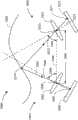
图15所表示的扫描方法基于三角测量原理。参考图15A的系统2560和图15B的系统4760给出三角测量原理的更加完整的解释。首先参考图15A,系统2560包括投射器2562和摄像装置2564。投射器2562包括位于源平面上的光2570的源图案和投射器透镜2572。投射器透镜可以包括若干透镜元件。投射器透镜具有透镜透视中心2575和投射光轴2576。光线2573从光的源图案上的点2571传播、穿过透镜透视中心而达到对象2590上,其中该光线在点2574处截止。The scanning method represented in Fig. 15 is based on the principle of triangulation. A more complete explanation of the principles of triangulation is given with reference to
摄像装置2564包括摄像装置透镜2582和光敏阵列2580。摄像装置透镜2582具有透镜透视中心2585和光轴2586。光线2583从对象点2574传播、穿过摄像装置透视中心2585并且在点2581处与光敏阵列2580相交。
连接各透视中心的线段是图15A中的基线2588和图15B中的基线4788。基线的长度被称作基线长度(2592,4792)。投射器光轴与基线之间的角是基线投射器角(2594,4794)。摄像装置光轴(2583,4786)与基线之间的角是基线摄像装置角(2596,4796)。在已知光的源图案上的点(2570,4771)与光敏阵列上的点(2581,4781)相对应的情况下,可以使用基线长度、基线投射器角和基线摄像装置角来确定连接点2585、2574和2575的三角形的边,因而确定对象2590的表面上的点相对于测量系统2560的参考坐标系的表面坐标。为此,使用透镜2572与平面2570之间的已知距离以及点2571与光轴2576和平面2570的交点之间的距离来求出投射器透镜2572与光的源图案2570之间的小三角形的边的角。将这些小角与较大角2596和2594适当相加或相减以获得期望的三角形角。本领域技术人员可知,可以使用等效的算术方法来求出三角形2574-2585-2575的各边的长度,或者可以使用其它相关三角形来获得对象2590的表面上的期望坐标。The line segments connecting the perspective centers are
首先参考图15B,除了系统4760不包括透镜以外,系统4760与图15A的系统2560类似。该系统可以包括投射器4762和摄像装置4764。在图15B所示的实施例中,投射器包括光源4778和光调制器4770。光源4778可以是激光光源,因为这种光源可以使用图15B的几何形状来在长距离内保持聚焦。来自光源4778的光线4773在点4771处照射光学调制器4770。来自光源4778的其它光线在调制器表面上的其它位置处照射光学调制器。在实施例中,光学调制器4770在多数情况下通过在一定程度上减少光学功率来改变发出光的功率。这样,光学调制器4770向处于光学调制器的表面的光施加这里被称为光的源图案的光学图案。光学调制器4770例如可以是DLP或LCOS装置。在一些实施例中,调制器4770是透射式的而非反射式的。从光学调制器4770出射的光呈现为从虚拟光透视中心4775出射的。光线呈现为从虚拟光透视中心4775出射、穿过点4771,并且传播至对象4790表面处的点4774。Referring first to FIG. 15B,
基线是从摄像装置透镜透视中心4785延伸至虚拟光透视中心4775的线段。通常,三角测量法涉及求出例如具有顶点4774、4785和4775的三角形的三角形的各边的长度。用于实现此的方式是求出基线的长度、基线与和摄像装置光轴4786之间的角以及基线与投射器参考轴4776之间的角。为了求出期望的角,求出另外较小的角。例如,可以通过基于从透镜到光敏阵列的距离及像素相对于摄像装置光轴的距离求解摄像装置透镜4782与光敏阵列4780之间的小三角形的角,来求出摄像装置光轴4786和光线4783之间的小角。然后,将小三角形的角与基线和摄像装置光轴之间的角相加以求出期望的角。与投射器类似,可以通过基于光源4777与光学调制的表面之间的已知距离及4771处的投射器像素相对于参考轴4776与光学调制器4770的表面的交点的距离求解这两个线之间的小三角形的角,来求出投射器参考轴4776与光线4773之间的角。从基线与投射器参考轴之间的角中减去该角以获得期望的角。The baseline is the line segment extending from the camera
摄像装置4764包括摄像装置透镜4782和光敏阵列4780。摄像装置透镜4782具有摄像装置透镜透视中心4785和摄像装置光轴4786。摄像装置光轴是摄像装置参考轴的示例。从数学观点看,在三角测量计算中可以同样容易地使用穿过摄像装置透镜透视中心的任何轴,但通常选择作为透镜的对称轴的摄像装置光轴。光线4783自对象点4774传播、穿过摄像装置透视中心4785并且与光敏阵列4780相交于点4781。本领域的普通技术人员显然可知,可以使用其它等同数学方法来求解三角形4774-4785-4775的各边的长度。
尽管这里所述的三角测量法是众所周知的,但为了完整性,以下给出一些附加技术信息。各透镜系统具有入射光瞳和出射光瞳。入射光瞳是在从一阶光学的角考虑时光出射的点。出射光瞳是在从透镜系统传播至光敏阵列时光出射的点。对于多元件透镜系统,入射光瞳和出射光瞳不必一致,并且相对于入射光瞳和出射光瞳的光线的角不必相同。然而,可以通过将透视中心视为透镜的入射光瞳、然后调整从透镜到源或图像面的距离以使得光线继续沿着直线传播以与源或图像面相交来简化模型。这样,获得了图15A所示的简单且广泛使用的模型。应当理解,该说明提供光的行为的良好一阶近似,但可以进行额外的精细校正,以补偿可能会导致光线相对于使用图15A的模型所计算出的位置略微偏移的透镜像差。尽管通常使用基线长度、基线投射器角和基线摄像装置角,但应当理解,在不丢失这里给出的说明的一般性的情况下,需要这些量并不排除可以应用其它相似但略有不同的公式的可能性。Although the triangulation methods described herein are well known, some additional technical information is given below for completeness. Each lens system has an entrance pupil and an exit pupil. The entrance pupil is the point at which light exits when considered from the perspective of first order optics. The exit pupil is the point at which light exits as it travels from the lens system to the photosensitive array. For a multi-element lens system, the entrance and exit pupils do not have to coincide, and the angles of the rays with respect to the entrance and exit pupils do not have to be the same. However, the model can be simplified by considering the center of perspective as the entrance pupil of the lens, and then adjusting the distance from the lens to the source or image plane so that rays continue to travel in straight lines to intersect the source or image plane. In this way, the simple and widely used model shown in Fig. 15A is obtained. It should be appreciated that this description provides a good first order approximation of the behavior of light, but that additional fine corrections can be made to compensate for lens aberrations that may cause light rays to shift slightly relative to their positions calculated using the model of Figure 15A. Although baseline length, baseline projector angle, and baseline camera angle are commonly used, it should be understood that the need for these quantities does not preclude other similar, but slightly different, applications without loss of generality of the description given here. Formula Possibilities.
在使用六DOF扫描仪的情况下,可以使用几种类型的扫描图案,并且组合不同类型以在最短时间内获得最佳性能可能是有利的。例如,在实施例中,快速测量方法使用可以在单次触发中获得三维坐标数据的二维编码图案。在使用编码图案的方法中,例如可以使用不同字符、不同形状、不同厚度或大小或者不同颜色来提供还已知为编码要素或编码特征的区别要素。这些特征可用来使得点2571与点2581一致。可以在光敏阵列2580上识别光的源图案2570上的编码特征。In the case of six DOF scanners, several types of scan patterns can be used, and it may be advantageous to combine different types to obtain the best performance in the shortest time. For example, in an embodiment, the rapid measurement method uses a two-dimensional encoded pattern that can obtain three-dimensional coordinate data in a single trigger. In methods using a coding pattern, for example different characters, different shapes, different thicknesses or sizes or different colors may be used to provide distinguishing elements, also known as coding elements or coding features. These features can be used to make
可以用来简化编码特征的一致的技术是使用核线。核线是由核面与源面2570或图像面2580的交线所形成的数学线。核平面是穿过投射器透视中心和摄像装置透视中心的任意平面。源平面和图像面上的何线在一些特殊情况下可以是平行的,但通常不平行。核线的方面是投射器平面上的给定核线在图像面上具有相应的核线。因而,在图像面中可以直接观察并且评估关于投射器平面中的核线的已知的任何特定图案。例如,在沿着可以使用利用光敏阵列2580的像素读出的值来确定图像面中的编码元件之间的间距的投射器平面中的核线配置编码图案的情况下,该信息用于确定对象点2574的三维坐标。还可以使编码图案以相对于核线的已知角倾斜并且高效地提取对象表面坐标。A consistent technique that can be used to simplify encoding features is to use epipolar lines. An epipolar line is a mathematical line formed by the intersection of the epipolar plane with the
使用编码图案的优点是可以快速获得对象表面点的三维坐标。然而,在多数情况下,诸如如上所述的正弦相位偏移方法的顺次结构光方法将得出更准确的结果。因此,用户可以有利地选择根据期望精度使用不同的投射方法来测量特定对象或特定对象区域或特征。通过使用可编程的光的源图案,可以容易地进行这种选择。The advantage of using a coded pattern is that the 3D coordinates of the object's surface points can be quickly obtained. However, in most cases sequential structured light methods such as the sinusoidal phase shift method described above will give more accurate results. Thus, a user may advantageously choose to use different projection methods for measuring specific objects or specific object regions or features depending on the desired accuracy. This selection can be easily made by using a programmable source pattern of light.
针对特定类型的对象可能存在扫描仪精度方面的重要限制。例如,可能难以有效地扫描诸如孔或凹部的特征。可能难以尽可能平滑地获得对象的边或孔。一些类型的材料不能返回所期望那么多的光或者可能具有针对光的大穿透深度。在其它情况下,光在返回至扫描仪之前可能从不止一个表面反射出来(多路径干涉)以使得观察光被“污染”,由此导致测量误差。在这些情况中的任意情况中,使用包括作为探测器延伸组件2550的一部分的触觉探测器(诸如探测器前端2554)的图15C所示的六DOF扫描仪2505来测量困难区域可能是有利的。在确定利用触觉探测器进行测量将是有利的之后,投射器2520可以发送激光束以照亮要测量的区域。在图15C中,光束的投射光线2522正照射对象2528上的点2527,这表示要利用探测器延伸组件2550测量该点。在一些情况中,可以将触觉探测器移动到投射器2550的投射场外部,从而避免缩小扫描仪的测量区域。在这种情况下,来自投射器的光束2522可以照射操作员可观看的区域。然后,操作员可以将触觉探测器2550移动至用以测量规定区域的位置。在其它情况下,要测量的区域可以在扫描仪的投射范围外部。在这种情况下,扫描仪可以将光束2522在其范围的程度上指向要测量的方向,或者扫描仪可以以表示光束应当放置的方向的图案移动光束2522。另一可能性是在显示监视器上呈现CAD模型或收集数据,然后在显示器上突出显示应重新测量的CAD模型的区域或收集数据。还可以使用例如球形安装的回射器或激光追踪器控制下的六DOF探测器的其它工具来测量突出显示区域。There may be important limitations in scanner accuracy for certain types of objects. For example, features such as holes or recesses may be difficult to scan efficiently. It can be difficult to get the edges or holes of an object to be as smooth as possible. Some types of materials do not return as much light as desired or may have a large penetration depth for light. In other cases, light may reflect off more than one surface before returning to the scanner (multipath interference) such that the viewing light is "contaminated", thereby causing measurement errors. In any of these cases, it may be advantageous to measure difficult areas using the six
投射器2520可以投射有时被称为结构光的二维光图案。这种光从投射器透镜透视中心出射并且以扩展图案向外传播直到其与对象2528相交为止。这种图案的示例是以上已论述的编码图案和周期图案这两者。投射器2520可以交替地投射一维光图案。这些投射器有时被称为激光线探测器或激光线扫描仪。尽管利用这种扫描仪投射的线具有宽度和形状(例如,其截面可以为高斯光束剖面),但其所包含的用于确定对象的形状的信息是一维的。因而,激光线扫描仪所发出的线以线形投射与对象相交。在对象上追踪的照明形状是二维的。相反,投射二维光图案的投射器在三维的对象上创建照明形状。在激光线扫描仪和结构光扫描仪之间进行区分的方式是将结构光扫描仪限定为包含至少三个非共线图案元素的一类扫描仪。对于投射编码光图案的二维图案的情况,由于三个非共线图案元素的代码而能够识别它们,并且由于这些元件是以二维方式投射的,因此至少三个图案元素必须是非共线的。对于诸如正弦重复图案的周期图案的情况,各正弦周期表示多个图案元素。由于存在二维的多个周期图案,因此这些图案元素必须是非共线的。相反,对于发出线光的激光线扫描仪的情况,所有的图案元素存在于直线上。尽管线具有宽度并且线截面的尾部与信号的峰相比可能具有较小的光学功率,但在求出对象的表面坐标时不是单独评估线的这些方面,因此这些方面并不表示单独的图案元素。尽管线可以包含多个图案元素,但这些图案元素是共线的。
现在将参考图15D来说明用于计算对象表面的三维坐标的方法。线扫描仪系统4500包括投射器4520和摄像装置4540。投射器4520包括光的源图案4521和投射器透镜4522。光的源图案包括线形式的照明图案。投射器透镜包括投射器透视中心和穿过该投射器透视中心的投射器光轴。在图15D的示例中,光束的中心光线4524与透视光轴对准。摄像装置4540包括摄像装置透镜4542和光敏阵列4541。透镜具有穿过摄像装置透镜透视中心4544的摄像装置光轴4543。在示例性系统4500中,与光束4524对准的投射器光轴以及摄像装置透镜光轴4544垂直于光的源图案4521所投射的线光4526。换句话说,线4526在垂直于图15D的纸的方向上。线照射对象表面,其中在距投射器第一距离处照射的是对象表面4510A并且在距投射器第二距离处照射是对象表面4520A。应当理解,在图15D的纸面以上或以下的不同高度处,对象表面可以处于与距对象表面4520A或4520B的距离不同的距投射器的距离处。对于同样存在于图15D的纸面上的线光4526上的点,线光与表面4520A相交于点4526,并且线光与表面4520B相交于点4527。对于交点4526的情况,光线自点4526穿过摄像装置透镜透视中心4544传播而与光敏阵列4541交于图像点4546。对于交点4527的情况,光线自点4527穿过摄像装置透镜透视中心传播而与光敏阵列4541交于图像点4547。通过注意相对于摄像装置透镜光轴4544的位置的交点的位置,可以确定从投射器(和摄像装置)到对象表面的距离。可以类似地求出从投射器到线光4526上的其它点(即不存在于图15D的纸面内的线光上的点)的距离。在通常情况下,光敏阵列上的图案将是线光(通常不是直线),其中该线中的各点与垂直于纸面的不同位置相对应,并且垂直于纸面的位置包含与从投射器到摄像装置的距离有关的信息。因此,通过评估光敏阵列的图像中的线的图案,可以求出沿着投射线的对象表面的三维坐标。注意,针对线扫描仪的情况的光敏阵列上的图像中所包含的信息包含在(通常并非笔直的)线中。相反,结构光的二维投射图案中所包含的信息包含光敏阵列中的图像的两个维度上的信息。A method for calculating the three-dimensional coordinates of the object surface will now be described with reference to FIG. 15D. The
应当注意,尽管以上给出的说明基于三个或更多个图案元素是否共线来在线扫描仪和区域(结构光)扫描仪之间进行区分,但应当注意,该标准的意图是将所投射的图案区分为区域和线。结果,仅具有沿着单个路径的信息的以线状方式投射的图案仍是线图案,尽管一维图案可能弯曲。It should be noted that although the description given above differentiates between line scanners and area (structured light) scanners based on whether three or more pattern elements are collinear, it should be noted that the intent of the standard is to The patterns are divided into areas and lines. As a result, a linearly projected pattern that only has information along a single path is still a linear pattern, although the one-dimensional pattern may be curved.
在一些情况下线扫描仪相对于结构光扫描仪的重要优点在于其具有更强的用于检测多路径干涉的能力。在普通(期望)情况下,从投射器出射并且照射对象表面的各光线可被视为通常在远离对象的方向上发生反射。对于通常情况,对象的表面不是高度反射性的(即,如镜状表面),因而几乎所有光发生漫反射(散射)而不是镜面反射。漫反射光不是如镜状表面的情况下的反射光那样全部在一个方向上传播而是以图案散射。然而,可以以与镜状表面反射光相同的方式找到散射光的一般方向。可以通过在来自投射器的光与对象的交点处绘制对象表面的法线来得出该方向。然后,找到散射光的一般方向作为入射光关于表面法线的反射。换句话说,尽管在这种情况下反射角仅是一般散射方向,但反射角与入射角相等。An important advantage of line scanners over structured light scanners in some cases is their greater ability to detect multipath interference. In the common (desired) case, each light ray exiting the projector and striking the surface of the object can be considered to be reflected generally in a direction away from the object. For the usual case, the surface of the object is not highly reflective (ie, like a specular surface), so almost all light is diffusely reflected (scattered) rather than specularly reflected. Diffuse reflected light does not travel all in one direction like the reflected light in the case of a specular surface but is scattered in a pattern. However, the general direction of scattered light can be found in the same way that light is reflected from specular surfaces. This direction can be derived by drawing the normal to the object's surface at the intersection of the light from the projector and the object. Then, find the general direction of the scattered light as the reflection of the incident light about the surface normal. In other words, the angle of reflection is equal to the angle of incidence, although in this case it is only the general scattering direction.
在照射对象表面的光的一部分在返回至摄像装置之前首先从对象的另一表面的散射情况下,出现多路径干涉的情况。对于对象上接收该散射光的点,发送至光敏阵列的光因而不仅对应于从投射器直接投射的光而且还对应于发送至投射器上的不同点并且从对象散射的光。特别是针对投射二维(结构)光的情况,多路径干涉的结果可能导致所计算出的从投射器到对象表面上的该点的距离不准确。The case of multipath interference arises in the case of scattering of a part of the light illuminating a surface of an object first from another surface of the object before returning to the camera. For a point on the object that receives this scattered light, the light sent to the photosensitive array thus corresponds not only to light projected directly from the projector but also to light sent to a different point on the projector and scattered from the object. Especially for the case of projecting two-dimensional (structured) light, the calculated distance from the projector to the point on the object surface may be inaccurate as a result of multipath interference.
对于线扫描仪的情况,存在用于确定是否存在多路径干涉的方式。在实施例中,光敏阵列的行平行于图15E的纸面并且列垂直于纸面。各行表示垂直于纸面的方向上的投射线4526上的一个点。在实施例中,通过首先计算各行的质心来求出针对线上的该点的从投射器到对象的距离。然而,各行上的光应集中于连续像素的区域。在存在接收大量光的两个或更多个区域的情况下,示出多路径干涉。在图15E中示出这种多路径干涉状况和由此产生的光敏阵列上的额外照明区域的示例。现在表面4510A在交点4526附近具有较大的曲率。交点处的表面法线是线4528,并且入射角是4531。根据与入射角相等的反射角4532求出光的反射线4529的方向。如上所述,光线4529实际上表示在角的范围内散射的光的整体方向。散射光的中心照射在对象4510A上的点4527,其中利用光敏阵列上的点4548处的透镜4544来对点4527摄像。在点4548附近接收到的意料之外高的光量表示可能存在多路径干涉。对于线扫描仪,对于多路径干涉的主要担心不是针对图15E所示的两个光斑4546和4541间隔相当大距离并且可以单独分析的情况,而是针对两个光点重叠或涂抹到一起的情况。在这种情况下,无法确定与期望点相对应的质心(在图15E中对应于点4546)。如通过再次参考图15E可以理解,该问题针对投射两个维度的光的扫描仪的情况变得更差。在需要在光敏阵列4541上成像的所有光以确定二维坐标的情况下,很显然,点4527处的光将与从投射器直接投射的光的期望图案以及从对象表面的反射而反射至点4527的不期望的光相对应。结果,在这种情况下,将可能针对二维投射光计算点4527错误的三维坐标。In the case of line scanners, there are ways to determine whether there is multipath interference. In an embodiment, the rows of the photosensitive array are parallel to the paper of Figure 15E and the columns are perpendicular to the paper. Each row represents a point on the
对于投射的线光,在多数情况下,可以通过改变该线的方向来消除多路径干涉。一个可能性是使用具有固有的二维性能的投射器来制作线扫描仪,由此使得能够扫频该线或者自动转动至不同方向。例如,在利用结构光所获得的特定扫描中怀疑多路径干涉的情况下,测量系统可被自动配置为切换至使用扫描线光的测量方法。For projected line lights, in most cases multipath interference can be eliminated by changing the direction of the line. One possibility is to make a line scanner using a projector that has inherent two-dimensional capabilities, thus enabling frequency sweeping of the line or automatic turning to different directions. For example, in case multipath interference is suspected in a particular scan obtained with structured light, the measurement system can be automatically configured to switch to a measurement method using scan line light.
用以消除多路径干涉的另一更彻底的方式是在示出了多路径干涉的区域内,扫频点光而不是线光或区域光。通过照射单个光点,没有其它照射点可以将散射光反射到期望测量的点上。例如,在扫描线4526作为各光点的集合的情况下,消除了多路径干涉的机会。Another more thorough way to eliminate multipath interference is to sweep spot lights instead of line lights or area lights in areas where multipath interference is shown. By illuminating a single point of light, no other illuminated point can reflect scattered light onto the point desired to be measured. For example, in the case of
在进行扫描仪测量时可能碰到的另一反射问题是反射镜面光的问题。有时,相对平滑的表面将具有曲率,以使得大量光被镜面反射到光敏阵列上,由此创建与周围像素相比获得更多光的“热点”。光的这些热点有时被称为“闪烁”。这些热点可能难以利用扫描仪来适当地测量对象。与多路径干涉的情况相同,可以通过使用具有可调整方向的激光线或光点来克服闪烁问题。Another reflection problem that may be encountered when taking scanner measurements is that of reflected specular light. Sometimes a relatively smooth surface will have a curvature such that a large amount of light is specularly reflected onto the photosensitive array, thereby creating a "hot spot" that gets more light than surrounding pixels. These hotspots of light are sometimes called "flickers." These hot spots can make it difficult to properly measure an object with a scanner. As in the case of multipath interference, the flicker problem can be overcome by using laser lines or spots with adjustable orientation.
由于可以容易地检测到光敏阵列上的小饱和区域,因此容易确定是否存在闪烁。然而,需要系统方法来识别和克服多路径问题。可以使用一般方法来评估多路径干涉并且还评估通常包括材料类型的分辨率和效果、表面质量和几何形状的质量。还参考图15F,在一个实施例中,可以在计算机控制下自动执行方法4600。步骤4602用来确定与被测对象的三维坐标有关的信息是否可用。第一种三维信息是CAD数据。CAD数据通常表示被测对象的标称尺寸。第二种三维信息是测量的三维数据,例如利用扫描仪或其它装置先前测量的数据。在一些情况下,步骤4602可以包括使坐标测量装置(例如,激光追踪器或六DOF扫描仪附件)的参考坐标系与对象的参考坐标系对准的另一步骤。在实施例中,这可以通过利用激光追踪器测量对象表面上的至少三个点来进行。The presence or absence of flicker is easily determined since small saturation regions on the photosensitive array can be easily detected. However, a systematic approach is needed to identify and overcome multipath problems. A general approach can be used to evaluate multipath interference and also evaluate resolution and effects typically including material type, surface quality and quality of geometry. Referring also to FIG. 15F, in one embodiment,
在针对步骤4602中提出的问题的回答是三维信息可用的情况下,在步骤4604中,使用计算机或处理器来计算对象测量相对于多路径干涉的易感性。在实施例中,这通过投射扫描仪投射器所发出的各光线并且计算各情况的角或反射来进行。参考图5E说明了针对线扫描仪情况给出的示例。以相同方式执行针对结构光源的计算。计算机或软件识别作为多路径干涉的结果容易发生错误的对象表面的各区域。步骤4604还可以对六DOF探测探测器的各位置相对于被测对象的多路径误差的易感性执行分析。在一些情况下,可以通过选择六DOF探测器相对于被测对象的适当位置和方位来避免多路径干涉或使多路径干涉最小。在针对步骤4602中提出的问题的回答是三维信息不可用的情况下,步骤4606用于使用任何期望或优选的测量方法来测量对象表面的三维坐标。在计算多路径干涉之后,可以执行步骤4608以评估期望的扫描质量的其它方面。一个这种质量因素是扫描的分辨率对于被测对象的特征而言是否充分。例如,在装置的分辨率为3mm并且存在期望有效扫描数据的亚毫米特征的情况下,应注意对象的这些问题区域以用于随后的校正动作。与分辨率部分相关的另一质量因素是用于测量对象的边缘和孔的边缘的能力。扫描仪性能的知识将使得能够确定扫描仪分辨率对于给定边缘而言是否足够好。另一质量因素是预期从给定特征返回的光量。预期到小的任何光从小孔内部、例如从掠射角返回至扫描仪。此外,根据材料的特定种类和颜色可以预期小光。特定种类的材料对于来自扫描仪的光可以具有大的穿透深度,并且在这种情况下无法期望良好的测量结果。在一些情况下,自动程序可能向用户询问补充信息。例如,在计算机程序正基于CAD数据执行步骤4604和4608的情况下,无法知晓正使用的材料的类型或被测对象的表面特性。在这些情况中,步骤4608可以包括用于获得被测对象的材料特性的另一步骤。Where the answer to the question posed in
在步骤4604和4608的分析之后,步骤4610用来决定是否应执行更多的诊断过程。可能的诊断过程的第一示例是用于以优选角投射条纹以注意是否观察到多路径干涉的步骤4612。以上参考图15E论述了针对投射线条纹的多路径干涉的一般指示。诊断步骤的另一示例是步骤4614,其中,步骤4614用来将在核线方向上对准的线的集合投射到光的源图案上,例如图15A中的光的源图案2570或图15B中的光的源图案4770上。对于光的源图案中的线光与核线对准的情况,这些线将呈现为光敏阵列上的图像面(例如图15A的面2580或图15B的面4780)上的直线。在光敏阵列上的这些图案不是直线或者这些线模糊或存在噪声的情况下,示出可能作为多路径干涉结果的问题。After the analysis of
步骤4616用来基于所进行的分析和诊断过程来选择优选动作的组合。在测量速度特别重要的情况下,可以优选使用编码光的2D(结构)图案来进行测量的步骤4618。在更大的精度更重要的情况下,可以优选使用利用顺次图案(例如相位和间距变化的正弦图案序列)的2D(结构)图案编码光进行测量的步骤4620。在选择方法4618或4620的情况下,可以期望还选择步骤4628,其中步骤4628用于重新确定扫描仪的位置,换句话说,步骤4628用于将扫描仪的位置和方位调整为使由步骤4604的分析所提供的多路径干涉和镜面反射(闪烁)最小的位置。可以通过利用来自扫描投射器的光照射问题区域或通过将这些区域显示在监视显示器上来向用户提供这些指示。可选地,可以利用计算机或处理器来自动选择测量过程中的下一步骤。在优选扫描仪位置无法消除多路径干涉和闪烁的情况下,存在几个选项。在一些情况下,可以利用重新定位的扫描仪和有效测量结果组合来重复测量。在其它情况下,代替使用结构光,可以在过程中增加可选测量步骤或者执行可选测量步骤。如前面所述,用于扫描条纹光的步骤4622提供在来自多路径干涉的问题的可能性降低的区域内获得信息的简便方式。在关注区域上扫频小光点的步骤4624还降低了来自多路径干涉的问题的可能性。利用触摸探测器或诸如SMR的其它机械传感器测量对象表面的区域的步骤消除了多路径干涉的可能性。触摸探测器提供基于探测器前端大小的已知分辨率,并且消除在一些被测对象中可能发现的光反射率低或光穿透深度大的问题。
在多数情况下,可以在步骤4630中基于从测量获得的数据结合以前执行的分析的结果来评估在步骤4618~4628的组合中收集到的数据的质量。在步骤4623中发现质量可接受的情况下,在步骤4634中完成测量。否则,在步骤4604中重新进行分析。在一些情况下,3D信息可能无法如期望地那样准确。在这种情况下,重复早期步骤中的一部分可能有帮助。In most cases, the quality of the data collected in the combination of steps 4618-4628 can be assessed in
在另一实施例中,摄像装置2530和投射器2520可被配置为测量过小而人眼无法看见的特征。通常,对于该应用,利用被配置为测量该大小的图案的摄像装置将缩小结构光图案的大小。使用这种投射器2500的应用的示例包括测量小焊点、测量表面粗糙度和波度、测量诸如纸张的材料的属性、测量切边、测量磨损、腐蚀和侵蚀以及测量平整度和台阶高度。图15的扫描仪系统(包括六DOF扫描仪和激光追踪器)使得能够在大区域内测量小特征。In another embodiment,
图16示出与光电系统900和定位摄像装置系统950相结合使用的六DOF指示器2800的实施例。结合图13论述了光电系统900和定位摄像装置系统950,并且这里将不重复该论述。在实施例中,以光电系统1900替换光电系统900。六DOF指示器2800包括主体2814、一个或多个回射器2810、2811、底座2890、可选电缆2836、可选电池2834、接口部件2812、识别元件2839、致动器按钮2816、天线2838和电子电路板2832。图16中的回射器2810、可选电缆2836、可选电池2834、接口部件2812、识别元件2839、致动器按钮2816、天线2838和电子电路板2832分别与图14中的回射器2010、可选电缆2046、可选电池2044、接口部件2012、识别元件2049、致动器按钮2016、天线2048和电子电路板2042相对应。针对这些对应元件的描述与以上所论述的相同并且将不重复。底座2890可以附接至移动元件,由此使得激光追踪器能够测量移动元件的六度。该移动元件可以是机器人末端执行器、机器工具或组件上工具(例如,组件线滑架)。由于回射器2810可能小并且图16中的很多其它元件是可选的且可以省略,因此六DOF指示器可以为紧凑型。该小尺寸在一些情况下可以提供优势。可以将诸如回射器2611的附加回射器添加至第一回射器2610以使得激光追踪器能够从各方向追踪六DOF扫描仪。FIG. 16 shows an embodiment of a six DOF indicator 2800 used in conjunction with an
图16A示出六DOF指示器4730是安装在磁槽4732上的六DOF球形安装回射器(SMR)4734的实施例。六DOF SMR可以包含可以为沿着反射元件的交线具有标记的露天或玻璃回射器的图案化回射器。在实施例中,操作者通过例如利用指向上方的标记或标志来将六DOF SMR定位成优选方位,来确定六DOF指示器的初始方位。利用该方法,六DOF指示器可以是完全无源的,而不需要来自任何其它装置的任何电力或任何电信号。由于可以将磁槽快速且容易地安装在任何期望位置(例如,机器人或机器工具上)而不需要安装任何电缆或复杂固定件,因此这种六DOF指示器提供了显著优点。在实施例中,通过将螺纹螺杆附接至螺纹开口4734,将磁槽4732附接至可以是机器人或机器工具的装置。在其它实施例中,利用热胶或环氧树脂将磁槽附接至装置。FIG. 16A shows an embodiment where the six
图16B示出实施例4760,其中,六DOF指示器4734是安装在具有约束4762的槽4732上的六DOF SMR。该约束包括与六DOF SMR4734相接触的元件,例如金属的机械件、塑料盖或带。通过固定机构4764使将该约束与六DOF SMR4734紧密物理接触。固定机构的示例包括挂钩夹或螺丝钳。约束4762提供保护以避免碰撞或高加速度。FIG. 16B shows an
图17示出与光电系统900和定位摄像装置系统950相结合使用的六DOF投射器2600的实施例。结合图13讨论了光电系统900和定位摄像装置系统950,并且这里将不重复该讨论。在实施例中,以具有两个或更多个波长的光的光电系统替换光电系统900。六DOF指示器2600包括主体2614、一个或多个回射器2610、2611、投射器2620、可选电缆2636、可选电池2634、接口部件2612、识别元件2639、致动器按钮2616、天线2638和电子电路板2632。图17中的回射器2610、可选电缆2636、可选电池2634、接口部件2612、识别元件2639、致动器按钮2616、天线2638和电子电路板2632分别与图14中的回射器2010、可选电缆2046、可选电池2044、接口部件2012、识别元件2049、致动器按钮2016、天线2048和电子电路板2042相对应。对于这些对应元件的描述与以上所讨论的相同并且将不重复。六DOF投射器2600可以包括光源、光源和转向镜、MEMS微镜、液晶投射器或者能够将光图案投射到工件2600上的任何其它装置。利用激光追踪器使用专利‘758所述的方法得知投射器2600的六自由度。根据该六自由度,可以在追踪器参考坐标系中求出投射光图案的三维坐标,而例如可以通过利用激光追踪器对工件上的三个点进行测量来将这些三维坐标转换到工件的参考坐标系中。可以将诸如回射器2611的附加回射器添加至第一回射器2610以使得激光追踪器能够从各种方向追踪六DOF扫描仪,由此在六DOF投射器2600可以投射光的方向上给出更大灵活性。FIG. 17 shows an embodiment of a six
在工件的参考坐标系中已知工件2660的表面上的投射光图案2640的情况下,可以获得各种有用能力。作为第一示例,投射图案可以表示操作员应在何处钻孔或者进行其它操作以使得能够将部件粘附到工件2600上。例如,可以将计量表附接至飞行器的驾驶舱。这种现场组装方法在多数情况中可以是具有成本效益的。作为第二示例,投射图案可以表示通过轮廓图案、颜色编码公差图案或其它图形部件的使用需要将哪些材料添加至工具或从工具移除。操作员可以使用工具来擦除不期望的材料或者使用填料来填充区域。由于激光追踪器或附接至激光追踪器的外部计算机可以知晓CAD模型的详细内容,因此六DOF投射器可以提供用于修改工具以满足CAD公差的相对快速简单的方法。其它组装操作可以包括划线、施加粘接剂、施加涂料、施加标签和清洗。作为第三示例,投射图案可以表示隐藏部件。例如,可以将管或电缆布置在表面下方并且从图中隐藏。可以将这些部件的位置投射到工件上,由此使得操作员能够避免进行组装或维修操作。With the projected
为了将来自投影扫描仪的光投射到工件的参考坐标系,通常需要在激光追踪器的参考坐标系中确定工件的参考坐标系。用于进行该操作的一个方式是利用激光追踪器来测量工件的表面上的三个点。然后,可以使用CAD模型或先前测量的数据来建立工件和激光追踪器之间的关系。In order to project the light from the projection scanner to the reference frame of the workpiece, it is usually necessary to determine the reference frame of the workpiece in the reference frame of the laser tracker. One way to do this is to use a laser tracker to measure three points on the surface of the workpiece. The relationship between the workpiece and the laser tracker can then be established using the CAD model or previously measured data.
在操作员通过六DOF投射器的辅助进行组装操作的情况下,有用的技术来将六DOF投射器安装在静止支架或底座上,由此使得操作员能够进行组装操作而无需利用双手。激光追踪器和六DOF投射器的有用模式是即使在激光追踪器停止追踪六DOF扫描仪上的回射器之后也使六DOF投射器继续投射光图案。这样,在投射器继续显示表示要进行的组装操作的光图案的情况下,操作员可以使用激光追踪器来进行测量,例如利用SMR、六DOF探测器或六DOF扫描仪。以类似的方式,在追踪器停止追踪各扫描投射器上的回射器的情况下,可以使用追踪器来设置继续投射图案的两个或更多个扫描投射器。因而,可以将高水平的细节投射到相对大的区域上,从而使得能够同时辅助几个操作员。还可以在模式中使得六DOF扫描仪能够投射几个可选图案中的任意可选图案,由此使得操作员能够进行作为规定序列的组装操作。Where an operator is assisted by a six DOF projector in the assembly operation, a useful technique is to mount the six DOF projector on a stationary stand or base, thereby enabling the operator to perform the assembly operation without the use of hands. A useful mode of the laser tracker and six DOF projector is to have the six DOF projector continue to project light patterns even after the laser tracker stops tracking the retroreflector on the six DOF scanner. In this way, while the projector continues to display a light pattern indicative of the assembly operation to be performed, the operator can use the laser tracker to take measurements, for example with an SMR, six DOF detector or six DOF scanner. In a similar manner, a tracker can be used to set up two or more scanning projectors that continue to project a pattern in the event that the tracker stops tracking the retroreflector on each scanning projector. Thus, a high level of detail can be projected onto a relatively large area, enabling several operators to be assisted at the same time. It is also possible in a mode to enable the six DOF scanner to project any of several selectable patterns, thereby enabling the operator to perform assembly operations as a prescribed sequence.
除了辅助组装操作之外,投影扫描仪还可以辅助执行检查过程。在一些情况下,检查过程可以要求操作员按特定顺序进行一系列测量。六DOF扫描仪可以指向操作员在各步骤要进行测量的位置。六DOF扫描仪可以对要进行测量的区域划分界线。例如,通过绘制框,六DOF扫描仪可以表示操作员要在框内的区域上进行扫描测量,可能要确定区域的平坦度或可以是较长的测量序列的一部分。由于投射器可以利用激光追踪器所追踪的六DOF回射器来继续一系列步骤,因此操作员可以使用追踪器或使用其它工具来继续检查序列。在追踪器正在进行测量的情况下,将知晓何时测量成功完成并且可以进入下一步骤。投影扫描仪还可以以书面消息或音频消息的形式来向操作员提供信息。操作员可以使用追踪器摄像装置或其它部件可以拍摄到的姿势来向激光追踪器发送命令。In addition to aiding assembly operations, projection scanners can also aid in the inspection process. In some cases, the inspection process may require the operator to take a series of measurements in a specific order. A six DOF scanner can be pointed at where the operator wants to take measurements at each step. The six DOF scanner can delineate the area to be measured. For example, by drawing a box, a six DOF scanner can indicate that the operator is to take a scan measurement over the area within the box, possibly to determine the flatness of the area or can be part of a longer measurement sequence. Since the projector can continue the sequence of steps with a six DOF retroreflector tracked by the laser tracker, the operator can use the tracker or use other tools to continue the inspection sequence. With the tracker taking measurements, it will be known when the measurement has completed successfully and the next step can be taken. Projection scanners can also provide information to operators in the form of written or audio messages. An operator can send commands to the laser tracker using gestures that can be captured by the tracker camera or other components.
六DOF投射器可以使用可能动态应用的光图案,以传输信息。例如,六DOF投射器可以使用前后运动来表示SMR要移动的方向。六DOF投射器可以绘制其它图案,以给出操作员根据一组规则可以解释的消息,其中这些规则以书面或显示形式对于用户而言是可用的。Six DOF projectors can use light patterns, possibly dynamically applied, to transmit information. For example, a six DOF projector can use forward and backward motion to indicate the direction the SMR is to move. The six DOF projector can draw other patterns to give a message that the operator can interpret according to a set of rules that are available to the user in written or displayed form.
还可以使用六DOF投射器来向用户输送与检查中的对象的性质有关的信息。例如,在进行了维度测量的情况下,六DOF投射器可以投射表示被测对象的表面坐标中关联的误差的区域的颜色编码图案。可选地,可以仅显示公差之外的区域或值。例如,可以突出显示表面轮廓在公差之外的区域。可选地,可以绘制线以表示在两个点之间测量的长度然后写关于与该距离相关联的误差量的部分的消息。A six DOF projector can also be used to convey information to the user about the properties of the object under inspection. For example, where a dimensional measurement has been made, a six DOF projector may project a color-coded pattern representing areas of associated error in the surface coordinates of the measured object. Optionally, only areas or values outside the tolerance can be displayed. For example, areas where the surface profile is outside tolerance can be highlighted. Optionally, one could draw a line to represent a length measured between two points and then write a partial message about the amount of error associated with that distance.
除了维度特性之外,六DOF投射器还可以显示与所测量的特性有关的信息,其中这些特性与对象上的坐标位置相关联。被测对象的这些特性可以包括温度值、超声值、微波值、毫米波值、X射线值、放射值、化学感测值和许多其它类型的值。如以下所述,可以测量这些对象特性并且使用六DOF扫描仪使这些对象特性与对象上的三维坐标一致。可选地,通过利用对象参考坐标系使数据以某种方式与对象表面的维度坐标相关,可以使用单独测量装置在对象上测量对象的特性。然后,通过使对象的参考坐标系与激光追踪器或六DOF投射器的参考坐标系一致,例如可以以图形形式将与对象特性有关的信息显示在对象上。例如,可以使用热红外阵列来测量对象表面的温度值。可以通过投射到对象表面上的颜色编码来表示各温度。In addition to dimensional properties, the six DOF projector can also display information about measured properties that are associated with coordinate positions on the object. These characteristics of the measured object may include temperature values, ultrasonic values, microwave values, millimeter wave values, x-ray values, radiation values, chemical sensing values, and many other types of values. As described below, these object properties can be measured and aligned to three-dimensional coordinates on the object using a six DOF scanner. Alternatively, a separate measurement device may be used to measure properties of the object on the object by using the object reference coordinate system to somehow relate the data to the dimensional coordinates of the object's surface. Then, by aligning the reference frame of the object with that of the laser tracker or the six DOF projector, information about the properties of the object can be displayed on the object, for example in graphical form. For example, a thermal infrared array can be used to measure the temperature value of the surface of an object. Each temperature can be represented by a color code projected onto the surface of the object.
六DOF扫描仪还可以将建模数据投射到对象表面上。例如,可以将热有限源分析(FEA)的结果投射到对象表面上,从而使得操作员能够选择在任一时间显示FEA或测量的热数据这两个显示中的哪个。由于这两组数据被投射到对象上的求出特性的实际位置处(例如测量或预测到特定温度存在的位置),因此向用户提供对于影响对象的物理效果的明确且直接的理解。还可以将六DOF投射器附接至诸如机器人或机器工具的可移动载体上。Six DOF scanners can also project modeling data onto object surfaces. For example, the results of thermal finite source analysis (FEA) can be projected onto the object surface, enabling the operator to choose which of the two displays to display, the FEA or the measured thermal data, at any one time. Since these two sets of data are projected onto the object at the actual location of the derived property (eg where a particular temperature is measured or predicted to exist), the user is provided with a clear and immediate understanding of the physical effects affecting the object. It is also possible to attach the six DOF projector to a movable carrier such as a robot or machine tool.
在利用人眼无法看见的过小的已解决特征进行小区域的测量的情况下,六DOF投射器可以将对象表面的一部分上先前测量的特性的放大图投射到对象表面上,由此使得用户能够观看不放大则看不见的过小特征。在实施例中,利用诸如图15的扫描仪2500的六DOF扫描仪来进行高分辨率测量,并且利用投射器(可以是六DOF扫描仪中的投射器或六DOF投射器)来投射结果。In the case of small area measurements using resolved features too small for the human eye to see, the six DOF projector can project a magnified view of previously measured properties on a portion of the object surface onto the object surface, thereby allowing the user to Ability to view features that are too small to be seen without magnification. In an embodiment, high resolution measurements are taken using a six DOF scanner, such as
图18示出与光电系统2790相结合使用的六DOF投射器2700的实施例。光电系统2790可以是能够测量六DOF投射器2700的六自由度的任何装置。在实施例中,光电系统2790包含用于观看六DOF投射器2700上的回射器的照明光源的一个或多个摄像装置。通过记录一个或多个摄像装置上光源图像的相对位置,求出三个方位自由度。例如,通过使用测距仪和两个角编码器求出回射器2710的三维坐标,来求出三个附加自由度。在另一实施例中,如下求出三个方位自由度:通过将光束经由立方隅角回射器2710的顶点发送至位置检测器来确定两个自由度,其中,位置检测器可以是光敏阵列;并且通过经由至少一个偏振分束器发送可以为相同光束的偏振光束来确定第三个自由度。在第三实施例中,光电组件2790将光图案发送至到六DOF投射器2700上。在本实施例中,接口部件2712包括多个线性位置检测器以检测图案并且据此确定六DOF投射器2700的三个方位自由度,其中,多个线性位置检测器可以为线性光敏阵列。如本领域普通技术人员已知的,许多其它光电系统2790也可以用来确定六DOF投射器2700的六自由度。六DOF投射器2700包括主体2714、一个或多个回射器2710、2711、投射器2720、可选电缆2736、可选电池2734、接口部件2712、识别元件2739、致动器按钮2716、天线2738和电子电路板2732。图18的可选电缆2736、可选电池2734、接口部件2712、识别元件2739、致动器按钮2716、天线2738和电子电路板2732分别对应于图14中的回射器2010、可选电缆2046、可选电池2044、接口部件2012、识别元件2049、致动器按钮2016、天线2048和电子电路板2042。针对这些对应元件的说明与上述相同并且将不进行重复。可以将诸如回射器2711的附加回射器添加至第一回射器2710以使得激光追踪器能够从各种方向追踪六DOF扫描仪,由此给出在利用六DOF投射器2700可以投射光的方向上的更大灵活性。FIG. 18 shows an embodiment of a six
返回参考图15,注意以下情况:除了提供与扫描仪摄像装置2530相结合使用的光源以外,扫描仪光源2520用作用于显示图案的投射器(用于确定工件的三维坐标),可以使用其它用于求出目标2500的六自由度的方法。尽管在图15中没有明确示出,但这些方法可以包括参考图18所述的方法。Referring back to FIG. 15, note the following: In addition to providing a light source for use in conjunction with the
除了图18的六DOF投射器可以使用比图17的六DOF投射器更宽范围的六DOF测量以外,图17和18相同。对六DOF投射器2600的应用所进行的所有评论还适用于六DOF投射器2700。17 and 18 are identical except that the six DOF projector of FIG. 18 can use a wider range of six DOF measurements than the six DOF projector of FIG. 17 . All comments made for the application of the six
图19示出与光电系统2790相结合使用的六DOF传感器4900的实施例。光电系统2790可以是能够测量六DOF传感器4900的六自由度的任何装置。在实施例中,光电系统2790包含用于观看六DOF传感器4900上的回射器的照明光源的一个或多个摄像装置。通过记录一个或多个摄像装置上的光源图像的相对位置,求出三个方位自由度。例如,通过使用测距仪和两个角编码器求出回射器4910的三维坐标,来求出三个附加自由度。在另一实施例中,如下求出三个方位自由度:通过将光束经由立方隅角回射器4910的顶点发送至位置检测器来确定两个自由度,其中,位置检测器可以是光敏阵列;并且通过经由至少一个偏振分束器发送可以是相同光束的偏振光束来确定第三个自由度。在第三实施例中,光电组件2790将光图案发送至六DOF传感器4900上。在本实施例中,接口部件4912包括多个线性位置检测器以检测图案并且据此确定六DOF投射器2700的三个方位自由度,其中,多个线性位置检测器可以是线性光敏阵列。如本领域普通技术人员已知的,许多其它光电系统2790可以用来确定六DOF投射器2700的六个自由度。六DOF传感器4900包括主体4914、一个或多个回射器4910、4911、传感器4920、可选源4950、可选电缆4936、可选电池4934、接口部件4912、识别元件4939、致动器按钮4916、天线4938和电子电路板4932。图18的可选电缆4936、可选电池4934、接口部件4912、识别元件4939、致动器按钮4916、天线4938和电子电路板4932分别对应于图14中的回射器2010、可选电缆2046、可选电池2044、接口部件2012、识别元件2049、致动器按钮2016、天线2048和电子电路板2042。对于这些对应元件的说明与上述相同并且将不进行重复。可以将诸如回射器4911的附加回射器添加至第一回射器4910以使得激光追踪器能够从各种方向追踪六DOF扫描仪,由此给出在六DOF传感器4900可以感测对象的方向上的更大灵活性。FIG. 19 shows an embodiment of a six
传感器4920可以具有各种类型。例如,其可以对光谱的红外区域中波长为0.7~20微米的光的光能做出反应,由此使得能够确定对象表面在点4924处的温度。传感器4920被配置为在通常以轴4922为中心的视野4940上收集对象4960所发出的红外能量。可以通过将轴4922投射到对象4960上并且求出交点4924,来求出与测量到的表面温度相对应的对象表面上的点的三维坐标。为了确定交点,需要知道对象参考坐标系和装置(追踪器)参考坐标系之间的关系,可选地,由于已知追踪器参考坐标系和传感器参考坐标系之间的关系,因此可以知道对象参考坐标系和六DOF传感器参考坐标系之间的关系。可选地,由于根据六DOF传感器上的追踪器进行的测量已知追踪器参考坐标系与六DOF传感器之间的关系,因此可以知道对象参考坐标系与六DOF传感器的参考坐标系之间的关系。用以确定对象参考坐标系和追踪器参考坐标系之间的关系的一种方式是测量对象表面上的三个点的三维坐标。通过具有与三个测量点相关的与对象有关的信息,将得知对象表面上的所有点。例如,根据CAD绘图或根据任意类型的坐标测量装置所进行的先前测量可以获得对象的与三个测量点有关的信息。The
除了测量所发出的红外能量之外,可以在宽范围波长或等同频率内测量(感测)电磁频谱。例如,电磁能可以在光学区域内并且可以包括可见光、紫外线、红外线和兆频区域。诸如对象根据对象的温度所发出的热能的一些特性是对象的固有属性并且不需要外部照明。可以根据照明的特性(例如各照明波长中可用的光学功率量)改变依赖于背景照明和感测结果的其它特性(诸如对象的颜色)。所测量的光学特性可以包括光学检测器所接收的光学功率,并且可以集成各种波长的能量以根据各波长处的光学检测器的响应性来产生电气响应。In addition to measuring emitted infrared energy, the electromagnetic spectrum can be measured (sensed) over a wide range of wavelengths or equivalent frequencies. For example, electromagnetic energy can be within the optical region and can include the visible, ultraviolet, infrared, and megafrequency regions. Some properties, such as the thermal energy emitted by an object depending on the temperature of the object, are intrinsic properties of the object and do not require external lighting. Other characteristics that depend on the background illumination and sensing results (such as the color of the object) may vary according to the characteristics of the illumination (eg, the amount of optical power available in each illumination wavelength). The measured optical properties may include the optical power received by the optical detector, and the energy at various wavelengths may be integrated to produce an electrical response based on the responsivity of the optical detector at each wavelength.
在一些情况下,可以利用源4950将照明有意地施加至对象。在正在执行期望将所施加的照明与背景照明区分的实验的情况下,例如,可以利用正弦波或方形波来调制所施加的光。然后,可以与传感器4920中的光学检测器结合使用锁定放大器或相似方法以仅提取所施加的光。In some cases, illumination may be intentionally applied to a
利用传感器4940感测电磁辐射的其它示例包括以比紫外光中存在的波长短的波长的X射线的感测和毫米波、微波和RF波等的感测及比在兆频波和其它光学波中存在的波长长的波长的示例。X射线可以用于穿透材料以获得与对象的内部特性有关的信息,例如存在缺陷或存在不止一种材料。源4950可以用来发出X射线以照亮对象4960。通过移动六DOF传感器4900并且从多个视图观察缺陷或材料界面的有无,可以确定材料内的缺陷或材料界面的三维坐标。此外,在将传感器4940与诸如图17和18的投射器2720的投射器相结合的情况下,可以将图案投射到表示需要执行维修工作以修补缺陷的对象表面上。Other examples of sensing electromagnetic radiation with
在实施例中,源4950在频谱(毫米波、微波或RF波)的电区域中提供电磁能。来自源的光照射对象4960,并且利用传感器4920拾取反射波或散射波。在实施例中,使用电波来穿透后方的墙壁或其它对象。例如,这种装置可以用来检测RFID标签的有无。这样,六DOF传感器4900可用来确定遍布于工厂内的RFID标签的位置。还可以定位除RFID标签以外的其它对象。例如,可以使用六DOF扫描仪来定位RF波或微波的源,诸如发出与计算机或其它电气装置发生干涉的高水平的宽带电磁能的焊接设备。In an embodiment, the
在实施例中,源4950提供超声波并且传感器4920是超声波传感器。超声波传感器相对于光学传感器在感测清晰对象、液位或高反射性或金属性表面的情况下具有优点。在医疗方面,可以使用超声波传感器来定位观看到的特征相对于患者身体的位置。传感器4920可以是被配置为检测微量化学成分并对检测到的化学成分提供化学识别标志的化学传感器。传感器4920可被配置为感测放射性衰变的有无,由此表示对象是否对人体照射造成风险。传感器4920可被配置为测量诸如表面粗糙度、波纹度和层叠的表面纹理。传感器可以是轮廓曲线仪、干涉仪、共焦显微镜、电容表或类似装置。六DOF扫描仪还可用于测量表面纹理。可以使用以上没有提到的其它类型的传感器来测量其它对象特性。In an embodiment,
图19A示出六DOF传感器4990的实施例,其中,除了六DOF传感器4990的传感器4922包括透镜4923和光敏阵列4924之外,图19A的六DOF传感器4990与图19的六DOF传感器4900相同。来自六DOF传感器的视野4940内的发射或反射能量线4925在对象表面4960上的点4926处出现、穿过传感器透镜4923的透视中心4927而到达光敏阵列4924上的点4928。源4950可以照亮对象表面4960的区域,由此在光敏阵列上产生响应。各点与对象表面上的感测特性的三维坐标、由三方位自由度所确定的各三维点、三个平移自由度、传感器组件内的摄像装置和投射器的几何形状、以及与对象表面上的点相对应的光敏阵列上的位置相关联。传感器4922的示例是热阵列传感器,其通过提供各像素处的温度来响应与三维表面坐标相关联的各特性传感器值。19A shows an embodiment of a six
图20是示出利用坐标测量装置和目标扫描仪来测量对象表面上的三个或更多个表面集的方法中的步骤5000的流程图,其中三个或更多个表面集中的每一个是装置参考坐标系中的对象表面上的点的三维坐标,每个表面集包括三个值,并且装置参考坐标系与坐标测量装置相关联。20 is a
步骤5005用于提供具有主体、第一回射器、投射器、摄像装置和扫描处理器的目标扫描仪,其中第一回射器、投射器和摄像装置刚性地固定至主体,并且目标扫描仪从坐标测量装置机械地拆卸。在该步骤中,投射器包括光的源图案(其中该光的源图案位于源平面上并且包括至少三个非共线图案元素),投射器被配置为将光的源图案投射到对象上以在对象上形成对象光图案,并且至少三个非共线图案元素各自与至少一个表面集相对应。此外,在该步骤中,摄像装置包括摄像装置透镜和光敏阵列,其中摄像装置透镜被配置为将光的对象图案成像在光敏阵列上作为光的图像图案,该光敏阵列包括摄像装置像素,该光敏阵列被配置为针对每个摄像装置像素产生与摄像装置像素从光的图案图案接收到的光量相对应的相应像素数字信号值。
步骤5010用于提供坐标测量装置,该坐标测量装置用于测量平移集和方位集,该平移集是装置参考坐标系中的目标扫描仪的三个平移自由度的值并且方位集是装置参考坐标系中的目标扫描仪的三个方位自由度的值,平移集和方位集足以限定目标扫描仪在空间内的位置和方位,坐标测量装置被配置为将第一光束发送至第一回射器并且从第一回射器接收第二光束,第二光束是第一光束的一部分,坐标测量装置包括装置处理器,装置处理器被配置为确定方位集和平移集,平移集基于第二光束中的至少一部分。此外,在该步骤中,扫描处理器和装置处理器联合地被配置为确定三个或更多个表面集,其中,每个表面集至少部分基于平移集、方位集和像素数字值。
步骤5015用于选择光的源图案。
步骤5020用于将光的源图案投射到对象上以产生光的对象图案。
步骤5025用于将光的对象图案在光敏阵列上成像以获得光的图像图案。
步骤5030用于获得光的图像图案的像素数字值。
步骤5035用于将第一光束从坐标测量装置发送至第一回射器。
步骤5040用于从第一回射器接收第二光束。
步骤5045用于测量方位集和平移集,其中该平移集至少部分基于第二光束。
步骤5050用于确定与至少三个非共线图案元素中的每一个相对应的表面集。
步骤5055用于保存表面集。该方法5000以标记A结束。
图21是示出图20的标记A之后的方法中的步骤5100的流程图。FIG. 21 is a flow
步骤5105用于使触觉探测器触摸对象表面。
步骤5110用于测量平移集和方位集。
步骤5115用于至少部分基于平移集和方位集来确定第二表面集。
图22是示出图20的标记A之后的方法中的步骤5200的流程图。步骤5205用于评估表面集。步骤5210用于至少部分基于所评估的表面集来向用户指示要利用触觉探测器测量的对象表面的区域。FIG. 22 is a flow
图23是示出图20的标记A之后的方法中的步骤5300的流程图。步骤5305用于将图案并入到第一回射器中。步骤5310用于提供包括第二透镜和第二光敏阵列的第二光学系统,其中该第二透镜被配置为使第一回射器的至少一部分的第二图像形成在第二光敏阵列上。步骤5315用于将第二图像转换成第二数字数据集。步骤5320用于至少部分基于第二数据数据集来计算方位集。FIG. 23 is a flow chart illustrating step 5300 in the method following label A of FIG. 20 . Step 5305 is for incorporating the pattern into the first retroreflector. Step 5310 is for providing a second optical system comprising a second lens and a second photosensitive array, wherein the second lens is configured to cause a second image of at least a portion of the first retroreflector to be formed on the second photosensitive array. Step 5315 is used to convert the second image into a second digital data set. Step 5320 is for computing a set of orientations based at least in part on the second data set.
图24是示出利用坐标测量装置和目标传感器来测量感测特性和与该感测特性相关联的表面集的方法中的步骤5400的流程图,其中表面集是装置参考坐标系中的对象表面上的点的三维坐标,每个表面集包括三个值,装置参考坐标系与坐标测量装置相关联。24 is a
步骤5405用于提供具有主体、第一回射器、传感器和传感器处理器的目标传感器,其中第一回射器和传感器刚性地固定至主体,并且目标传感器从坐标测量装置机械地拆卸,目标传感器被配置为测量感测特性,感测特性是与传感器所测量的量相关联的值。
步骤5410用于提供坐标测量装置,其中该坐标测量装置用于测量平移集和方位集,平移集是装置参考坐标系中的目标传感器的三个平移自由度的值并且方位集是装置参考坐标中的目标传感器的三个方位自由度的值,平移集和方位集足以限定目标传感器在空间内的位置和方位,坐标测量装置用于将第一光束发送至第一回射器并且从第一回射器接收第二光束,第二光束是第一光束的一部分,坐标测量装置包括装置处理器,装置处理器被配置为确定方位集和平移集,平移集至少部分基于第二光束,其中传感器处理器和装置处理器共同地被配置为确定感测特性和表面集,表面集至少部分基于平移集和方位集。
步骤5415用于将来自坐标测量装置的第一光束发送至第一回射器。
步骤5420用于从第一回射器接收第二光束。
步骤5425用于测量方位集和平移集,该平移集至少部分基于第二光束。Step 5425 is for measuring a set of orientations and a set of translations based at least in part on the second light beam.
步骤5430用于确定表面集。Step 5430 is used to determine the surface set.
步骤5435用于感测该感测特性。Step 5435 is for sensing the sensing characteristic.
步骤5440用于保存表面集和感测特性。方法5400以标记B结束。Step 5440 is used to save surface sets and sensing properties.
图25是示出以图24的标记B开始的方法中的步骤5500的流程图。步骤5505用于将图案并入到第一回射器内。FIG. 25 is a
步骤5510用于提供包括第二透镜和第二光敏阵列的光学系统,该第二透镜用于将图案化后的回射器的至少一部分的第二图像形成在第二光敏阵列上。
步骤5515用于将第二图像转换成第二数字数据集。
步骤5520用于至少部分基于第二数字数据集来计算方位集。
图26是示出用于通过利用第一目标投射器投射第一图案来将第一信息传输至坐标测量装置的用户的方法中的步骤5600的流程图。26 is a flowchart illustrating steps 5600 in a method for transmitting first information to a user of a coordinate measuring device by projecting a first pattern with a first target projector.
步骤5605用于提供具有目标投射器参考坐标系并且包括主体、第一回射器和投射器的第一目标投射器,其中该第一回射器和投射器刚性地固定至主体,第一目标投射器从坐标测量装置机械地拆卸,投射器被配置为以两个维度投射光图案,其中该光图案在与三维对象相交时形成三维光图案。Step 5605 is for providing a first object projector having an object projector reference frame and comprising a body, a first retro-projector and a projector, wherein the first retro-projector and projector are rigidly fixed to the body, the first object A projector is mechanically detached from the coordinate measuring device, the projector being configured to project a light pattern in two dimensions, wherein the light pattern forms a three-dimensional light pattern when intersecting the three-dimensional object.
步骤5610用于提供具有装置参考坐标系的坐标测量装置,其中该坐标测量装置用于测量平移集和方位集,平移集是装置参考坐标系中的第一目标投射器的三个平移自由度的值并且方位集是装置参考坐标系中的第一目标投射器的三个方位自由度的值,平移集和方位集足以限定第一目标投射器在空间内的位置和方位,坐标测量装置用于将第一光束发送至第一回射器并且从第一回射器接收第二光束,第二光束是第一光束的一部分,坐标测量装置包括装置处理器,装置处理器被配置为确定方位集和平移集,平移集至少部分基于第二光束。Step 5610 is for providing a coordinate measurement device with a device reference frame for measuring a translation set and an orientation set, the translation set being the translational degrees of freedom of the first target projector in the device reference frame The value and the orientation set are the values of the three orientation degrees of freedom of the first object projector in the reference coordinate system of the device. The translation set and the orientation set are sufficient to define the position and orientation of the first object projector in space. The coordinate measuring device is used for sending a first light beam to a first retroreflector and receiving a second light beam from the first retroreflector, the second light beam being a portion of the first light beam, the coordinate measuring device comprising a device processor configured to determine a set of orientations and a set of translations based at least in part on the second light beam.
步骤5615用于将来自坐标测量装置的第一光束发送至第一回射器。Step 5615 is for sending the first light beam from the coordinate measuring device to the first retroreflector.
步骤5620用于从第一回射器接收第二光束。Step 5620 is for receiving a second light beam from the first retroreflector.
步骤5625用于测量方位集和平移集,其中该平移集至少部分基于第二光束。Step 5625 is for measuring a set of orientations and a set of translations, wherein the set of translations is based at least in part on the second light beam.
步骤5630用于选择要输送的第一信息,该第一信息选自对象上的位置、对象上的多个位置、由移动图案指示的方向、包括一个或多个符号或字母数字字符的消息、隐藏特征、测量对象特性、建模特性、表面特性的放大表示、具有根据规则的含义的图案以及以上的组合。Step 5630 is for selecting first information to be delivered selected from a location on an object, a plurality of locations on an object, a direction indicated by a movement pattern, a message comprising one or more symbols or alphanumeric characters, Hidden features, measured object properties, modeled properties, enlarged representations of surface properties, patterns with rule-based meaning, and combinations of the above.
步骤5635用于确定与第一信息相对应的光的第一图案。Step 5635 is for determining a first pattern of light corresponding to the first information.
步骤5640用于存储第一图案。Step 5640 is for storing the first pattern.
步骤5645用于至少部分基于平移集和方位集来将光的第一图案从投射器投射到对象上。方法5600以标记C结束。Step 5645 is for projecting a first pattern of light from the projector onto the object based at least in part on the translation set and the orientation set. Method 5600 ends with marker C.
图27是示出以图26的标记C开始的方法中的步骤5700的流程图。步骤5705用于在第一目标投射器继续将光的第一图案投射到对象上的情况下,利用坐标测量装置进行测量。FIG. 27 is a
图28是示出以图26的标记C开始的方法中的步骤5800的流程图。步骤5805用于提供具有第三回射器的第二目标投射器。步骤5810用于将第一光束发送至第三回射器。步骤5815用于使第二光束从第三回射器返回至坐标测量装置。FIG. 28 is a
图29是示出以图26的标记C开始的方法中的步骤5900的流程图。步骤5905用于将图案并入到第一回射器中。步骤5910用于提供第二光学系统。步骤5915用于将第二图像转换成第二数字数据集。步骤5920用于至少部分基于第二数字数据集来计算方位集。FIG. 29 is a
图30是示出以图26的标记C开始的方法中的步骤6000的流程图。步骤6005用于向第一目标投射器提供扬声器。步骤6010用于选择要输送的第二信息。步骤6015用于确定与第二信息相对应的第一音频消息。步骤6020用于从扬声器发出第一音频消息。FIG. 30 is a
图31是示出用于利用坐标测量装置和目标扫描仪测量对象表面上的多个表面集的流程图,其中每个表面集是装置参考坐标系中的对象表面上的点的三维坐标,每个表面集包括三个值,装置参考坐标系与坐标测量装置相关联。31 is a flowchart illustrating a method for measuring multiple surface sets on an object surface using a coordinate measuring device and a target scanner, where each surface set is the three-dimensional coordinates of a point on the object surface in the device reference coordinate system, each A surface set consists of three values, the device reference frame associated with the coordinate measuring device.
步骤6015用于提供目标扫描仪,其具有主体、并入图案的第一回射器、投射器、摄像装置和扫描处理器,其中第一回射器、投射器和摄像装置刚性地附接至主体,并且目标扫描仪从坐标测量装置机械地拆卸,其中投射器包括光的源图案,该光的源图案位于源平面上并且包括多个共线图案元素,投射器被配置为将光的源图案投射到对象上以在对象上形成光的对象图案,每个图案元素与至少一个表面集相对应,其中摄像装置包括第一透镜和第一光敏阵列,该第一透镜被配置为将光的对象图案成像在第一光敏阵列上作为光的图像图案,第一光敏阵列包括摄像装置像素,第一光敏阵列被配置为针对每个摄像装置像素产生与摄像装置像素从光的图像图案接收到的光量相对应的相应像素数字值。
步骤6110用于提供坐标测量装置,其中该坐标测量装置被配置为测量平移集和方位集,平移集是装置参考坐标系中的目标扫描仪的三个平移自由度的值并且方位集是装置参考坐标系中的目标扫描仪的三个方位自由度的值,平移集和方位集足以限定目标扫描仪在空间内的位置和方位,坐标测量装置用于将第一光束发送至第一回射器并且从第一回射器接收第二光束,第二光束是第一光束的一部分,坐标测量装置包括装置处理器,装置处理器被配置为确定方位集和平移集,方位集和平移集至少部分基于第二光束,坐标测量装置包括第二光学系统,该第二光学系统包括第二透镜和第二光敏阵列,第二透镜用于使第一回射器的至少一部分的第二图像形成在第二光敏阵列上,坐标测量装置用于将第二图像转换成第二数字数据集并且至少部分基于第二数字数据集来计算方位集,其中扫描处理器和装置处理器共同被配置为确定多个表面集,其中,每个表面集至少部分基于平移集、方位集和像素数字值。Step 6110 is for providing a coordinate measurement device configured to measure a translation set and an orientation set, the translation set being the values of the three translational degrees of freedom of the target scanner in the device reference frame and the orientation set being the device reference The values of the three orientation degrees of freedom of the target scanner in the coordinate system, the translation set and the orientation set are sufficient to define the position and orientation of the target scanner in space, and the coordinate measuring device is used to send the first beam to the first retroreflector and receiving a second light beam from the first retroreflector, the second light beam being a portion of the first light beam, the coordinate measurement device includes a device processor configured to determine a set of orientations and a set of translations, the set of orientations and the set of translations being at least in part Based on the second light beam, the coordinate measuring device includes a second optical system including a second lens and a second photosensitive array, the second lens being used to form a second image of at least a portion of the first retroreflector at the second On two photosensitive arrays, a coordinate measuring device is used to convert the second image into a second digital data set and to calculate a set of orientations based at least in part on the second digital data set, wherein the scan processor and the device processor are collectively configured to determine a plurality of Surface sets, wherein each surface set is based at least in part on a translation set, an orientation set, and a pixel numerical value.
步骤6115用于选择光的源图案。
步骤6120用于将光的源图案投射到对象上以产生光的对象图案。
步骤6125用于使光的对象图案在光敏阵列上成像以获得光的图像图案。
步骤6130用于针对光的图像图案获得像素数字值。
步骤6135用于将第一光束从坐标测量装置发送至第一回射器。
步骤6140用于从第一回射器接收第二光束。
步骤6145用于至少部分基于第二光束来测量方位集和平移集。
步骤6150用于确定与多个共线图案元素相对应的表面集。
步骤6155用于保存表面集。
图32是示出用于利用坐标测量装置和目标扫描仪来测量对象表面上的多个表面集的步骤6200的流程图,其中每个表面集是装置参考坐标系中的对象表面上的点的三维坐标,每个表面集包括三个值,装置参考坐标系与坐标测量装置相关联。32 is a
步骤6205用于提供目标扫描仪,其具有主体、第一回射器、投射器、摄像装置和扫描处理器,其中第一回射器、投射器和摄像装置刚性地固定至主体,并且目标扫描仪从坐标测量装置机械地拆卸,其中投射器包括光的源图案,该光的源图案位于源平面上并且包括多个共线图案元素,投射器用于将光的源图案投射到对象上以在对象上形成光的对象图案,其中各图案元素与至少一个表面集相对应,其中摄像装置包括第一透镜和第一光敏阵列,第一透镜被配置为使光的对象图案形成在第一光敏阵列上作为光的图像图案,第一光敏阵列包括摄像装置像素,第一光敏阵列被配置为针对各摄像装置像素产生与摄像装置像素从光的图像图案接收到的光量相对应的相应像素数字值。
步骤6210用于提供坐标测量装置,其中该坐标测量装置被配置为测量平移集和方位集,平移集是装置参考坐标系中的目标扫描仪的三个平移自由度的值并且方位集是装置参考坐标系中的目标扫描仪的三个方位自由度的值,平移集和方位集足以限定目标扫描仪在空间内的位置和方位,坐标测量装置用于将第一光束发送至第一回射器并且从第一回射器接收第二光束,第二光束是第一光束的一部分,坐标测量装置包括装置处理器,装置处理器被配置为确定方位集和平移集,方位集和平移集至少部分基于第二光束,其中扫描仪处理器和装置处理器共同被配置为确定多个表面集,其中每个表面集至少部分基于平移集、方位集和像素数字值。
步骤6215用于选择光的源图案。
步骤6220用于将光的源图案投射到对象上以产生光的对象图案。
步骤6225用于使光的对象图案在光敏阵列上成像以获得光的图像图案。
步骤6230用于针对光的图像图案获得像素数字值。
步骤6235用于将第一光束从坐标测量装置发送至第一回射器。
步骤6240用于从第一回射器接收第二光束。
步骤6245用于测量方位集和平移集,其中平移集至少部分基于第二光束。
步骤6250用于确定与多个共线图案元素相对应的表面集。
步骤6255用于保存表面集。
尽管已经参考示例实施例说明了本发明,但本领域技术人员应当理解,可以在没有背离本发明的范围的情况下进行各种变化并且可以利用等同物来替换元件。另外,可以在没有背离本发明的实质范围的情况下进行多种变形以使特定情形或材料适合本发明的教导。因此,期望本发明不限于作为用于执行本发明考虑的最佳模式所公开的特定实施例,但本发明将包括落在所附权利要求书的范围内的所有实施例。此外,术语第一、第二等的使用并不表示任何顺序或重要度,而是使用术语第一、第二等来将各元件区分开。此外,术语“一”、“一个”等的使用并不表示量的限制,而是表示存在至少一个所引用的项。While the invention has been described with reference to exemplary embodiments, it will be understood by those skilled in the art that various changes may be made and equivalents may be substituted for elements without departing from the scope of the invention. In addition, many modifications may be made to adapt a particular situation or material to the teachings of the invention without departing from the essential scope thereof. Therefore, it is intended that the invention not be limited to the particular embodiment disclosed as the best mode contemplated for carrying out this invention, but that the invention will include all embodiments falling within the scope of the appended claims. Furthermore, the use of the terms first, second, etc. does not imply any order or degree of importance, but the terms first, second, etc. are used to distinguish elements. Furthermore, use of the terms "a", "an", etc. does not imply a limitation of quantity but rather means that there is at least one of the recited item.
Claims (19)
Applications Claiming Priority (5)
| Application Number | Priority Date | Filing Date | Title |
|---|---|---|---|
| US201161475703P | 2011-04-15 | 2011-04-15 | |
| US61/475,703 | 2011-04-15 | ||
| US201261592049P | 2012-01-30 | 2012-01-30 | |
| US61/592,049 | 2012-01-30 | ||
| PCT/US2012/032970WO2012142062A2 (en) | 2011-04-15 | 2012-04-11 | Six degree-of-freedom laser tracker that cooperates with a remote structured-light scanner |
Publications (1)
| Publication Number | Publication Date |
|---|---|
| CN103649676Atrue CN103649676A (en) | 2014-03-19 |
Family
ID=45955180
Family Applications (11)
| Application Number | Title | Priority Date | Filing Date |
|---|---|---|---|
| CN201280018625.XAPendingCN103649673A (en) | 2011-04-15 | 2012-03-23 | Enhanced position detector in laser tracker |
| CN201280018614.1APendingCN103765238A (en) | 2011-04-15 | 2012-03-28 | Laser tracker that combines two different wavelengths with a fiber-optic coupler |
| CN201280018596.7APendingCN103502842A (en) | 2011-04-15 | 2012-03-30 | Absolute distance meter that uses a fiber-optic switch to reduce drift |
| CN2012800186156APendingCN103477245A (en) | 2011-04-15 | 2012-04-09 | Absolute distance meter based on an undersampling method |
| CN201280018632.XAPendingCN103703363A (en) | 2011-04-15 | 2012-04-11 | Six degree-of-freedom laser tracker that cooperates with a remote sensor |
| CN201280018621.1AExpired - Fee RelatedCN103492870B (en) | 2011-04-15 | 2012-04-11 | Cooperate with the long-range projector with the six degree of freedom laser traces device of mail message |
| CN201280018665.4APendingCN103688132A (en) | 2011-04-15 | 2012-04-11 | 6DOF Laser Tracker Collaborating with Remote Line Scanner |
| CN201280018679.6APendingCN103649676A (en) | 2011-04-15 | 2012-04-11 | Six-DoF Laser Tracker Collaborating with Remote Structured Light Scanner |
| CN2012800186207APendingCN103477184A (en) | 2011-04-15 | 2012-04-13 | Gimbal instrument having a prealigned and replaceable optics bench |
| CN2012800183904APendingCN103477188A (en) | 2011-04-15 | 2012-04-13 | Laser tracker with enhanced handling components |
| CN201280018667.3AExpired - Fee RelatedCN103703389B (en) | 2011-04-15 | 2012-04-16 | Laser Tracker with Enhanced Lighting Indicator |
Family Applications Before (7)
| Application Number | Title | Priority Date | Filing Date |
|---|---|---|---|
| CN201280018625.XAPendingCN103649673A (en) | 2011-04-15 | 2012-03-23 | Enhanced position detector in laser tracker |
| CN201280018614.1APendingCN103765238A (en) | 2011-04-15 | 2012-03-28 | Laser tracker that combines two different wavelengths with a fiber-optic coupler |
| CN201280018596.7APendingCN103502842A (en) | 2011-04-15 | 2012-03-30 | Absolute distance meter that uses a fiber-optic switch to reduce drift |
| CN2012800186156APendingCN103477245A (en) | 2011-04-15 | 2012-04-09 | Absolute distance meter based on an undersampling method |
| CN201280018632.XAPendingCN103703363A (en) | 2011-04-15 | 2012-04-11 | Six degree-of-freedom laser tracker that cooperates with a remote sensor |
| CN201280018621.1AExpired - Fee RelatedCN103492870B (en) | 2011-04-15 | 2012-04-11 | Cooperate with the long-range projector with the six degree of freedom laser traces device of mail message |
| CN201280018665.4APendingCN103688132A (en) | 2011-04-15 | 2012-04-11 | 6DOF Laser Tracker Collaborating with Remote Line Scanner |
Family Applications After (3)
| Application Number | Title | Priority Date | Filing Date |
|---|---|---|---|
| CN2012800186207APendingCN103477184A (en) | 2011-04-15 | 2012-04-13 | Gimbal instrument having a prealigned and replaceable optics bench |
| CN2012800183904APendingCN103477188A (en) | 2011-04-15 | 2012-04-13 | Laser tracker with enhanced handling components |
| CN201280018667.3AExpired - Fee RelatedCN103703389B (en) | 2011-04-15 | 2012-04-16 | Laser Tracker with Enhanced Lighting Indicator |
Country Status (7)
| Country | Link |
|---|---|
| US (12) | US8537376B2 (en) |
| EP (1) | EP2545396B1 (en) |
| JP (11) | JP2014516409A (en) |
| CN (11) | CN103649673A (en) |
| DE (10) | DE112012001708B4 (en) |
| GB (11) | GB2504890A (en) |
| WO (11) | WO2012141868A1 (en) |
Cited By (13)
| Publication number | Priority date | Publication date | Assignee | Title |
|---|---|---|---|---|
| CN107016733A (en)* | 2017-03-08 | 2017-08-04 | 北京光年无限科技有限公司 | Interactive system and exchange method based on augmented reality AR |
| CN110634179A (en)* | 2018-06-22 | 2019-12-31 | 阿莱恩技术有限公司 | Method for generating digital three-dimensional model using intraoral three-dimensional scanner |
| CN111492262A (en)* | 2017-10-08 | 2020-08-04 | 魔眼公司 | Distance measurement using warp grid pattern |
| CN111557637A (en)* | 2019-02-13 | 2020-08-21 | 深圳市斯尔顿科技有限公司 | Ophthalmologic measuring system |
| CN111656260A (en)* | 2018-01-24 | 2020-09-11 | 赛博光学公司 | Structured light projection for mirrored surfaces |
| CN111665257A (en)* | 2020-07-02 | 2020-09-15 | 北京智机科技有限公司 | Glue type detection scanning system and detection method thereof |
| CN112352137A (en)* | 2018-05-25 | 2021-02-09 | 艾美创有限公司 | Motion encoder |
| CN113209600A (en)* | 2015-08-07 | 2021-08-06 | 索尼互动娱乐股份有限公司 | System and method for determining position of photoelectric sensor using MEMS projector |
| CN113316704A (en)* | 2019-01-11 | 2021-08-27 | 新加坡科技研究局 | Apparatus and method for evaluating surface roughness |
| CN113785195A (en)* | 2019-05-13 | 2021-12-10 | Abb瑞士股份有限公司 | Nondestructive testing of test objects on workpieces |
| CN114675289A (en)* | 2020-12-10 | 2022-06-28 | 得利捷Ip科技有限公司 | Targeting and triangulation in multi-sensor scanners |
| CN114761829A (en)* | 2020-03-09 | 2022-07-15 | 日本电气株式会社 | Management system |
| US12178685B2 (en) | 2018-06-22 | 2024-12-31 | Align Technology, Inc. | Dental scanning system with structured light projection |
Families Citing this family (253)
| Publication number | Priority date | Publication date | Assignee | Title |
|---|---|---|---|---|
| US8488972B2 (en)* | 2006-05-30 | 2013-07-16 | Tai-Her Yang | Directional control/transmission system with directional light projector |
| US9482755B2 (en) | 2008-11-17 | 2016-11-01 | Faro Technologies, Inc. | Measurement system having air temperature compensation between a target and a laser tracker |
| US8803055B2 (en)* | 2009-01-09 | 2014-08-12 | Automated Precision Inc. | Volumetric error compensation system with laser tracker and active target |
| US8659749B2 (en) | 2009-08-07 | 2014-02-25 | Faro Technologies, Inc. | Absolute distance meter with optical switch |
| US9772394B2 (en) | 2010-04-21 | 2017-09-26 | Faro Technologies, Inc. | Method and apparatus for following an operator and locking onto a retroreflector with a laser tracker |
| US8619265B2 (en) | 2011-03-14 | 2013-12-31 | Faro Technologies, Inc. | Automatic measurement of dimensional data with a laser tracker |
| US9400170B2 (en) | 2010-04-21 | 2016-07-26 | Faro Technologies, Inc. | Automatic measurement of dimensional data within an acceptance region by a laser tracker |
| US9377885B2 (en) | 2010-04-21 | 2016-06-28 | Faro Technologies, Inc. | Method and apparatus for locking onto a retroreflector with a laser tracker |
| RU2010124265A (en)* | 2010-06-16 | 2011-12-27 | Алексей Владиславович Жданов (RU) | METHOD AND DEVICE FOR DETERMINING THE DIRECTION OF THE START OF MOTION |
| USD684580S1 (en)* | 2010-07-26 | 2013-06-18 | Faro Technologies, Inc. | Laser scanner |
| US8411285B2 (en)* | 2010-11-22 | 2013-04-02 | Trimble Navigation Limited | Stationing an unleveled optical total station |
| CN102096069B (en)* | 2010-12-17 | 2012-10-03 | 浙江大学 | Real-time processing system and method for phased array three-dimensional acoustic camera sonar |
| US8902408B2 (en) | 2011-02-14 | 2014-12-02 | Faro Technologies Inc. | Laser tracker used with six degree-of-freedom probe having separable spherical retroreflector |
| GB2503390B (en) | 2011-03-03 | 2014-10-29 | Faro Tech Inc | Target apparatus and method |
| GB201105587D0 (en)* | 2011-04-01 | 2011-05-18 | Elliptic Laboratories As | User interfaces for electronic devices |
| USD688577S1 (en) | 2012-02-21 | 2013-08-27 | Faro Technologies, Inc. | Laser tracker |
| US9164173B2 (en) | 2011-04-15 | 2015-10-20 | Faro Technologies, Inc. | Laser tracker that uses a fiber-optic coupler and an achromatic launch to align and collimate two wavelengths of light |
| JP2014516409A (en) | 2011-04-15 | 2014-07-10 | ファロ テクノロジーズ インコーポレーテッド | Improved position detector for laser trackers. |
| US9686532B2 (en) | 2011-04-15 | 2017-06-20 | Faro Technologies, Inc. | System and method of acquiring three-dimensional coordinates using multiple coordinate measurement devices |
| US9482529B2 (en) | 2011-04-15 | 2016-11-01 | Faro Technologies, Inc. | Three-dimensional coordinate scanner and method of operation |
| US9147199B2 (en) | 2011-06-17 | 2015-09-29 | Google Inc. | Advertisements in view |
| JP2014522981A (en) | 2011-07-13 | 2014-09-08 | ファロ テクノロジーズ インコーポレーテッド | Apparatus and method for determining three-dimensional coordinates of an object using a spatial light modulator |
| GB2507022A (en) | 2011-07-14 | 2014-04-16 | Faro Tech Inc | Grating-based scanner with phase and pitch adjustment |
| US9444981B2 (en)* | 2011-07-26 | 2016-09-13 | Seikowave, Inc. | Portable structured light measurement module/apparatus with pattern shifting device incorporating a fixed-pattern optic for illuminating a subject-under-test |
| EP2600173A1 (en)* | 2011-11-29 | 2013-06-05 | Hexagon Technology Center GmbH | Method for operating a laser scanner |
| WO2013112455A1 (en) | 2012-01-27 | 2013-08-01 | Faro Technologies, Inc. | Inspection method with barcode identification |
| CN102540170B (en)* | 2012-02-10 | 2016-02-10 | 江苏徕兹光电科技股份有限公司 | Based on calibration steps and the distance measuring equipment thereof of the phase measurement of dual-wavelength laser pipe |
| CN104662388B (en)* | 2012-05-07 | 2018-06-26 | 卡尔蔡司工业测量技术有限公司 | For the replaceable lighting module of coordinate measuring machine |
| GB2540075B (en)* | 2012-05-18 | 2017-04-19 | Acergy France SAS | Improvements relating to pipe measurement |
| TWI549655B (en)* | 2012-05-18 | 2016-09-21 | 國立成功大學 | Joint range of motion measuring apparatus and measuring method thereof |
| US9671566B2 (en) | 2012-06-11 | 2017-06-06 | Magic Leap, Inc. | Planar waveguide apparatus with diffraction element(s) and system employing same |
| US9733717B2 (en)* | 2012-07-12 | 2017-08-15 | Dual Aperture International Co. Ltd. | Gesture-based user interface |
| US9354051B2 (en) | 2012-09-13 | 2016-05-31 | Laser Technology, Inc. | System and method for a rangefinding instrument incorporating pulse and continuous wave signal generating and processing techniques for increased distance measurement accuracy |
| US9213101B2 (en)* | 2012-09-13 | 2015-12-15 | Laser Technology, Inc. | Self-aligned aiming system and technique for a laser rangefinder incorporating a retroreflector |
| US9879995B2 (en) | 2012-09-13 | 2018-01-30 | Laser Technology, Inc. | System and method for superimposing a virtual aiming mechanism with a projected system beam in a compact laser-based rangefinding instrument |
| US9383753B1 (en) | 2012-09-26 | 2016-07-05 | Google Inc. | Wide-view LIDAR with areas of special attention |
| DE102012112025B4 (en) | 2012-12-10 | 2016-05-12 | Carl Zeiss Ag | Method and devices for determining the position of a kinematics |
| CA2884029C (en)* | 2012-12-20 | 2019-02-26 | Raytheon Canada Limited | Wide field of view multibeam optical apparatus |
| DE102012223929A1 (en)* | 2012-12-20 | 2014-06-26 | Hilti Aktiengesellschaft | Method and device for determining the two-dimensional location coordinates of a target object |
| CN103134441A (en)* | 2012-12-28 | 2013-06-05 | 中国空气动力研究与发展中心设备设计及测试技术研究所 | Large wind tunnel flexible spraying pipe laser tracking measurement method |
| DE102013104490A1 (en)* | 2013-01-25 | 2014-07-31 | Werth Messtechnik Gmbh | Method and device for determining the geometry of structures by means of computer tomography |
| US9036134B2 (en)* | 2013-02-12 | 2015-05-19 | Faro Technologies, Inc. | Multi-mode optical measurement device and method of operation |
| US9746560B2 (en) | 2013-02-12 | 2017-08-29 | Faro Technologies, Inc. | Combination scanner and tracker device having a focusing mechanism |
| US9188430B2 (en) | 2013-03-14 | 2015-11-17 | Faro Technologies, Inc. | Compensation of a structured light scanner that is tracked in six degrees-of-freedom |
| US9046360B2 (en) | 2013-03-14 | 2015-06-02 | Faro Technologies, Inc. | System and method of acquiring three dimensional coordinates using multiple coordinate measurement devices |
| US9041914B2 (en) | 2013-03-15 | 2015-05-26 | Faro Technologies, Inc. | Three-dimensional coordinate scanner and method of operation |
| CN105190232A (en)* | 2013-03-15 | 2015-12-23 | 法罗技术股份有限公司 | Three-dimensional coordinate scanner and method of operation |
| US9294758B2 (en)* | 2013-04-18 | 2016-03-22 | Microsoft Technology Licensing, Llc | Determining depth data for a captured image |
| US9234742B2 (en) | 2013-05-01 | 2016-01-12 | Faro Technologies, Inc. | Method and apparatus for using gestures to control a laser tracker |
| EP2801839B1 (en)* | 2013-05-10 | 2020-03-04 | Leica Geosystems AG | Handheld measuring aid for use with a 6-DoF laser tracker |
| TWI487115B (en)* | 2013-06-07 | 2015-06-01 | Sinopower Semiconductor Inc | Ditch type power element and manufacturing method thereof |
| US9476695B2 (en)* | 2013-07-03 | 2016-10-25 | Faro Technologies, Inc. | Laser tracker that cooperates with a remote camera bar and coordinate measurement device |
| US9113154B2 (en) | 2013-07-10 | 2015-08-18 | Faro Technologies, Inc. | Three-dimensional measurement device having three-dimensional overview camera |
| WO2015006784A2 (en) | 2013-07-12 | 2015-01-15 | Magic Leap, Inc. | Planar waveguide apparatus with diffraction element(s) and system employing same |
| US10228242B2 (en) | 2013-07-12 | 2019-03-12 | Magic Leap, Inc. | Method and system for determining user input based on gesture |
| US10812694B2 (en) | 2013-08-21 | 2020-10-20 | Faro Technologies, Inc. | Real-time inspection guidance of triangulation scanner |
| FR3009881B1 (en) | 2013-08-23 | 2017-03-17 | Stmi Soc Des Techniques En Milieu Ionisant | 3D TOPOGRAPHIC AND RADIOLOGICAL MODELING OF AN ENVIRONMENT |
| US9443310B2 (en)* | 2013-10-09 | 2016-09-13 | Microsoft Technology Licensing, Llc | Illumination modules that emit structured light |
| EP2866047B1 (en)* | 2013-10-23 | 2020-12-23 | Ladar Limited | A detection system for detecting an object on a water surface |
| EP2881704B1 (en)* | 2013-12-04 | 2018-05-09 | Hexagon Technology Center GmbH | Systems and methods for automated measurement of an object and corresponding computer programme product |
| US9121689B2 (en)* | 2013-12-11 | 2015-09-01 | Faro Technologies, Inc. | Method for correcting a spherically mounted retroreflector when resetting a distance meter |
| US9239238B2 (en)* | 2013-12-11 | 2016-01-19 | Faro Technologies, Inc. | Method for correcting a 3D measurement of a spherically mounted retroreflector on a nest |
| US9594250B2 (en) | 2013-12-18 | 2017-03-14 | Hexagon Metrology, Inc. | Ultra-portable coordinate measurement machine |
| US9606235B2 (en)* | 2014-01-16 | 2017-03-28 | The Boeing Company | Laser metrology system and method |
| US10451482B2 (en) | 2014-02-14 | 2019-10-22 | Palo Alto Research Center Incorporated | Determination of color characteristics of objects using spatially modulated light |
| US9952033B2 (en) | 2014-02-14 | 2018-04-24 | Palo Alto Research Center Incorporated | Spatial modulation of light to determine object length |
| US10061027B2 (en)* | 2014-02-25 | 2018-08-28 | Adsys Controls, Inc. | Laser navigation system and method |
| USD730946S1 (en) | 2014-03-05 | 2015-06-02 | Franklin B White | Mount for an excavation control unit |
| CN103984193B (en)* | 2014-03-14 | 2020-10-16 | 广州虹天航空科技有限公司 | Photographing apparatus stabilizer and control method thereof |
| USD734337S1 (en)* | 2014-04-01 | 2015-07-14 | Datalogic Ip Tech S.R.L. | Coded information reader |
| USD735595S1 (en) | 2014-04-02 | 2015-08-04 | Franklin B White | Support for GPS apparatus |
| US9400174B2 (en)* | 2014-04-07 | 2016-07-26 | Palo Alto Research Center Incorporated | Monitor for particle injector |
| US9739591B2 (en)* | 2014-05-14 | 2017-08-22 | Faro Technologies, Inc. | Metrology device and method of initiating communication |
| US9829305B2 (en) | 2014-05-14 | 2017-11-28 | Faro Technologies, Inc. | Metrology device and method of changing operating system |
| US9921046B2 (en)* | 2014-05-14 | 2018-03-20 | Faro Technologies, Inc. | Metrology device and method of servicing |
| US9903701B2 (en) | 2014-05-14 | 2018-02-27 | Faro Technologies, Inc. | Articulated arm coordinate measurement machine having a rotary switch |
| US9746308B2 (en) | 2014-05-14 | 2017-08-29 | Faro Technologies, Inc. | Metrology device and method of performing an inspection |
| US9803969B2 (en)* | 2014-05-14 | 2017-10-31 | Faro Technologies, Inc. | Metrology device and method of communicating with portable devices |
| DE102014007908A1 (en)* | 2014-05-27 | 2015-12-03 | Carl Zeiss Meditec Ag | Surgical System |
| US10021379B2 (en) | 2014-06-12 | 2018-07-10 | Faro Technologies, Inc. | Six degree-of-freedom triangulation scanner and camera for augmented reality |
| US9402070B2 (en) | 2014-06-12 | 2016-07-26 | Faro Technologies, Inc. | Coordinate measuring device with a six degree-of-freedom handheld probe and integrated camera for augmented reality |
| DE102014009269B4 (en)* | 2014-06-25 | 2017-06-08 | Thyssenkrupp Ag | Device for the spatial alignment of a non-contact measuring head |
| US9395174B2 (en) | 2014-06-27 | 2016-07-19 | Faro Technologies, Inc. | Determining retroreflector orientation by optimizing spatial fit |
| US9291447B2 (en)* | 2014-07-09 | 2016-03-22 | Mitutoyo Corporation | Method for controlling motion of a coordinate measuring machine |
| US11879995B2 (en) | 2014-07-10 | 2024-01-23 | Brunson Instrument Company | Laser tracker calibration system and methods |
| WO2016007918A1 (en) | 2014-07-10 | 2016-01-14 | Aaron Hudlemeyer | Laser tracker calibration system and methods |
| EP2980526B1 (en) | 2014-07-30 | 2019-01-16 | Leica Geosystems AG | Coordinate measuring device and method |
| GB2543459A (en)* | 2014-08-11 | 2017-04-19 | Faro Tech Inc | A six degree-of-freedom triangulation scanner and camera for augmented reality |
| DE102014113395B4 (en)* | 2014-09-17 | 2017-05-18 | Deutsches Zentrum für Luft- und Raumfahrt e.V. | Method and installation for measuring surfaces |
| KR20160034719A (en)* | 2014-09-22 | 2016-03-30 | 한화테크윈 주식회사 | Lidar system |
| US10176625B2 (en) | 2014-09-25 | 2019-01-08 | Faro Technologies, Inc. | Augmented reality camera for use with 3D metrology equipment in forming 3D images from 2D camera images |
| JP1529086S (en)* | 2014-09-30 | 2016-10-31 | ||
| US9897690B2 (en) | 2014-10-27 | 2018-02-20 | Laser Technology, Inc. | Technique for a pulse/phase based laser rangefinder utilizing a single photodiode in conjunction with separate pulse and phase receiver circuits |
| CN104266611A (en)* | 2014-10-29 | 2015-01-07 | 中航成飞民用飞机有限责任公司 | Auxiliary tool for testing central line of clamping hole of plane escape door stopping block |
| DE102014224851A1 (en)* | 2014-12-04 | 2016-06-09 | Siemens Aktiengesellschaft | Apparatus and method for displaying structural information about a technical object |
| US9506744B2 (en)* | 2014-12-16 | 2016-11-29 | Faro Technologies, Inc. | Triangulation scanner and camera for augmented reality |
| US10126415B2 (en) | 2014-12-31 | 2018-11-13 | Faro Technologies, Inc. | Probe that cooperates with a laser tracker to measure six degrees of freedom |
| WO2016118637A1 (en) | 2015-01-20 | 2016-07-28 | Volfson Leo | Single aperture laser range finder |
| US9651658B2 (en) | 2015-03-27 | 2017-05-16 | Google Inc. | Methods and systems for LIDAR optics alignment |
| JP6550849B2 (en)* | 2015-03-30 | 2019-07-31 | セイコーエプソン株式会社 | Projector and projector control method |
| JP6601489B2 (en)* | 2015-03-31 | 2019-11-06 | 株式会社ニコン | Imaging system, imaging apparatus, imaging method, and imaging program |
| GB2538385B (en)* | 2015-04-28 | 2021-09-22 | Faro Tech Inc | Combination scanner and tracker device having a focusing mechanism |
| JP6533691B2 (en)* | 2015-04-28 | 2019-06-19 | 株式会社トプコン | Three-dimensional position measurement system |
| JP6533690B2 (en)* | 2015-04-28 | 2019-06-19 | 株式会社トプコン | Three-dimensional position measurement system |
| US10512508B2 (en) | 2015-06-15 | 2019-12-24 | The University Of British Columbia | Imagery system |
| CN106443697A (en)* | 2015-08-06 | 2017-02-22 | 信泰光学(深圳)有限公司 | Self-propelled device and environment distance measuring device thereof |
| JP6553999B2 (en)* | 2015-09-17 | 2019-07-31 | 株式会社トプコン | Polygon mirror and fan beam output device and surveying system |
| GB2542762B (en) | 2015-09-21 | 2018-11-21 | Imetrum Ltd | Measuring device and method |
| EP3165876A3 (en)* | 2015-11-03 | 2017-07-26 | Hexagon Technology Center GmbH | Opto-electronic measuring device |
| CN105372642B (en)* | 2015-11-06 | 2017-08-29 | 中国人民解放军空军装备研究院雷达与电子对抗研究所 | A kind of VHD laser two-dimension scanning device measured based on modulating frequency |
| US10757394B1 (en) | 2015-11-09 | 2020-08-25 | Cognex Corporation | System and method for calibrating a plurality of 3D sensors with respect to a motion conveyance |
| US11562502B2 (en) | 2015-11-09 | 2023-01-24 | Cognex Corporation | System and method for calibrating a plurality of 3D sensors with respect to a motion conveyance |
| US10812778B1 (en) | 2015-11-09 | 2020-10-20 | Cognex Corporation | System and method for calibrating one or more 3D sensors mounted on a moving manipulator |
| US10539661B2 (en)* | 2015-11-25 | 2020-01-21 | Velodyne Lidar, Inc. | Three dimensional LIDAR system with targeted field of view |
| EP3173739A1 (en)* | 2015-11-30 | 2017-05-31 | HILTI Aktiengesellschaft | Method for controlling and/or calibrating a vertical axis of a rotation laser |
| JP6644892B2 (en)* | 2015-12-20 | 2020-02-12 | アップル インコーポレイテッドApple Inc. | Light detection distance measuring sensor |
| US10101154B2 (en)* | 2015-12-21 | 2018-10-16 | Intel Corporation | System and method for enhanced signal to noise ratio performance of a depth camera system |
| DE102015122846A1 (en)* | 2015-12-27 | 2017-06-29 | Faro Technologies, Inc. | Method for optically scanning and measuring an environment by means of a 3D measuring device and near-field communication |
| JP6668764B2 (en)* | 2016-01-13 | 2020-03-18 | セイコーエプソン株式会社 | Image recognition device, image recognition method, and image recognition unit |
| US9815204B2 (en)* | 2016-01-22 | 2017-11-14 | The Boeing Company | Apparatus and method to optically locate workpiece for robotic operations |
| EP3199913B1 (en) | 2016-01-28 | 2019-04-03 | Leica Geosystems AG | Device for automatically locating a moveable geodesic target object |
| US11157072B1 (en)* | 2016-02-24 | 2021-10-26 | Apple Inc. | Direct retinal projector |
| AU2017224228B2 (en)* | 2016-02-26 | 2022-03-24 | Think Surgical, Inc. | Method and system for guiding user positioning of a robot |
| US9752865B1 (en) | 2016-04-07 | 2017-09-05 | International Business Machines Corporation | Height measurement using optical interference |
| US9800330B1 (en) | 2016-05-03 | 2017-10-24 | Microsoft Technology Licensing, Llc | Methods and systems for providing a fiber optic cable network testing platform |
| TWI595252B (en)* | 2016-05-10 | 2017-08-11 | 財團法人工業技術研究院 | Distance measurement device and distance measuring method thereof |
| JP6748908B2 (en)* | 2016-05-24 | 2020-09-02 | 清水建設株式会社 | Intelligent reflective target |
| US10563330B2 (en) | 2016-06-08 | 2020-02-18 | One Sciences, Inc. | Methods and systems for stitching along a predetermined path |
| JP7187324B2 (en)* | 2016-06-13 | 2022-12-12 | ヴィクサー,エルエルシー | Improved self-mixing module using filters |
| US10107650B2 (en) | 2016-06-15 | 2018-10-23 | The Boeing Company | Systems and methods for measuring angular position of a laser beam emitter |
| US10027410B2 (en) | 2016-06-23 | 2018-07-17 | Abl Ip Holding Llc | System and method using a gated retro-reflector for visible light uplink communication |
| JP6823482B2 (en)* | 2016-07-04 | 2021-02-03 | 株式会社トプコン | 3D position measurement system, 3D position measurement method, and measurement module |
| ES2899284T3 (en) | 2016-07-15 | 2022-03-10 | Fastbrick Ip Pty Ltd | Vehicle incorporating a brick laying machine |
| ES2899585T3 (en) | 2016-07-15 | 2022-03-14 | Fastbrick Ip Pty Ltd | Material transport boom |
| JP6857979B2 (en)* | 2016-07-27 | 2021-04-14 | 株式会社トプコン | Laser scanner optics and surveying equipment |
| US10884127B2 (en)* | 2016-08-02 | 2021-01-05 | Samsung Electronics Co., Ltd. | System and method for stereo triangulation |
| US10546373B2 (en) | 2016-08-03 | 2020-01-28 | Sightline Innovation Inc. | System and method for integrated laser scanning and signal processing |
| US10298913B2 (en)* | 2016-08-18 | 2019-05-21 | Apple Inc. | Standalone depth camera |
| US10551164B2 (en) | 2016-08-19 | 2020-02-04 | National Research Council Of Canada | Method, kit and target for multimode 3D imaging systems |
| US10408574B2 (en)* | 2016-08-24 | 2019-09-10 | The Boeing Company | Compact laser and geolocating targeting system |
| US9948395B2 (en)* | 2016-09-12 | 2018-04-17 | The United States Of America As Represented By Secretary Of The Navy | System and method for line-of-sight optical broadcasting using beam divergence and an orbiting or airborne corner cube reflector |
| US20180088202A1 (en) | 2016-09-23 | 2018-03-29 | Faro Technologies, Inc. | Apparatus and method for relocating an articulating-arm coordinate measuring machine |
| US20180095174A1 (en) | 2016-09-30 | 2018-04-05 | Faro Technologies, Inc. | Three-dimensional coordinate measuring device |
| US10099774B2 (en)* | 2016-10-12 | 2018-10-16 | The Boeing Company | System and method for correcting wing twist of an aircraft |
| US10401154B2 (en)* | 2016-10-12 | 2019-09-03 | The Boeing Company | Apparatus and method to detect aircraft wing deflection and twist during flight |
| DE102016220708A1 (en) | 2016-10-21 | 2018-04-26 | Volkswagen Aktiengesellschaft | Lidar sensor and method for optically sensing an environment |
| ES2743298T3 (en)* | 2016-10-27 | 2020-02-18 | Pepperl Fuchs Ag | Measuring device and procedure for triangulation measurement |
| US10486060B2 (en) | 2016-11-23 | 2019-11-26 | Microsoft Technology Licensing, Llc | Tracking core for providing input to peripherals in mixed reality environments |
| EP3565104B1 (en)* | 2016-12-28 | 2021-08-11 | Alps Alpine Co., Ltd. | Device and method for acquiring information relating to rotation of direct current commutator motor motor |
| US10866320B2 (en) | 2017-01-13 | 2020-12-15 | Faro Technologies, Inc. | Remote control of a laser tracker using a mobile computing device |
| US10546427B2 (en) | 2017-02-15 | 2020-01-28 | Faro Technologies, Inc | System and method of generating virtual reality data from a three-dimensional point cloud |
| KR102353513B1 (en)* | 2017-03-16 | 2022-01-20 | 주식회사 히타치엘지 데이터 스토리지 코리아 | Rotary distance measuring apparatus |
| US10378442B2 (en)* | 2017-03-31 | 2019-08-13 | The Boeing Company | Mechanical flywheel for bowed rotor mitigation |
| WO2019005260A1 (en) | 2017-06-29 | 2019-01-03 | Apple Inc. | Time-of-flight depth mapping with parallax compensation |
| ES2648643B2 (en)* | 2017-07-04 | 2018-07-25 | Javier IBAÑEZ CRUZ | POSITIONING SYSTEM |
| WO2019006511A1 (en) | 2017-07-05 | 2019-01-10 | Fastbrick Ip Pty Ltd | Real time position and orientation tracker |
| US10684124B1 (en)* | 2017-07-20 | 2020-06-16 | Michael Hanchett | Scanning and measurement system for repair of structures |
| US10534084B2 (en)* | 2017-07-27 | 2020-01-14 | Blackmore Sensors & Analytics, Llc | Method and system for using square wave digital chirp signal for optical chirped range detection |
| CN107290739B (en)* | 2017-08-04 | 2020-06-16 | 美国西北仪器公司 | Detector assembly, detector and laser ranging system |
| CN111213098B (en) | 2017-08-17 | 2024-03-15 | 快砖知识产权私人有限公司 | Communication systems for interactive systems |
| WO2019033170A1 (en) | 2017-08-17 | 2019-02-21 | Fastbrick Ip Pty Ltd | Laser tracker with improved roll angle measurement |
| CN107655459B (en)* | 2017-09-07 | 2020-11-27 | 南京理工大学 | A method for measuring and calculating the roughness of rock structures in the field |
| JP7084705B2 (en)* | 2017-09-13 | 2022-06-15 | 株式会社トプコン | Surveying device |
| CN111212799B (en) | 2017-10-11 | 2023-04-14 | 快砖知识产权私人有限公司 | Machine for conveying objects and multi-compartment carousel for use therewith |
| CN107631710B (en)* | 2017-10-26 | 2023-07-18 | 清华大学深圳研究生院 | Connecting device for inclined bridge type cross beam of fixed bridge type measuring machine |
| US10402640B1 (en)* | 2017-10-31 | 2019-09-03 | Intuit Inc. | Method and system for schematizing fields in documents |
| KR102054562B1 (en)* | 2017-11-10 | 2019-12-10 | 김진형 | Measuring Instrument for Sizing Object at Long Distance |
| JP7179844B2 (en) | 2017-11-13 | 2022-11-29 | ヘキサゴン メトロロジー,インコーポレイテッド | Thermal management of optical scanning equipment |
| US10591603B2 (en) | 2017-11-15 | 2020-03-17 | Faro Technologies, Inc. | Retroreflector acquisition in a coordinate measuring device |
| KR102403544B1 (en) | 2017-12-18 | 2022-05-30 | 애플 인크. | Time-of-flight sensing using an addressable array of emitters |
| US10887723B2 (en) | 2017-12-22 | 2021-01-05 | Qualcomm Incorporated | Millimeter wave ranging with six degrees of freedom |
| CN108253931B (en)* | 2018-01-12 | 2020-05-01 | 内蒙古大学 | Binocular stereo vision ranging method and ranging device thereof |
| KR102061040B1 (en)* | 2018-02-02 | 2019-12-31 | 호서대학교 산학협력단 | Invisible LiDAR or Laser Scanning Apparatus |
| CN108667523B (en)* | 2018-03-06 | 2021-02-26 | 苏州大学 | Optical Fiber Nonlinear Equalization Method Based on KNN Algorithm Without Data Aid |
| JP6911803B2 (en)* | 2018-03-23 | 2021-07-28 | 豊田合成株式会社 | Near infrared sensor cover |
| US10949992B2 (en)* | 2018-04-12 | 2021-03-16 | Francis Bretaudeau | Localization system with a cooperative optronic beacon |
| US10565718B2 (en)* | 2018-04-18 | 2020-02-18 | Faro Technologies, Inc. | System and method of scanning an environment |
| US10274979B1 (en) | 2018-05-22 | 2019-04-30 | Capital One Services, Llc | Preventing image or video capture of input data provided to a transaction device |
| KR102637175B1 (en)* | 2018-07-02 | 2024-02-14 | 현대모비스 주식회사 | Lidar sensing device |
| US12214500B2 (en) | 2018-07-16 | 2025-02-04 | Fastbrick Ip Pty Ltd | Backup tracking for an interaction system |
| CN112689552A (en) | 2018-07-16 | 2021-04-20 | 快砖知识产权私人有限公司 | Active damping system |
| JP7257113B2 (en)* | 2018-08-01 | 2023-04-13 | 株式会社キーエンス | Three-dimensional coordinate measuring device |
| US11619481B2 (en) | 2018-08-13 | 2023-04-04 | Faro Technologies, Inc. | Coordinate measuring device |
| US11590623B2 (en) | 2018-08-13 | 2023-02-28 | Triton Metal Products Inc. | Machine integrated positioning system |
| USD866364S1 (en) | 2018-08-20 | 2019-11-12 | Faro Technologies, Inc. | Measurement device |
| EP3627100B1 (en)* | 2018-09-20 | 2021-12-01 | Hexagon Technology Center GmbH | Retro reflector with fisheye lens |
| USD875573S1 (en) | 2018-09-26 | 2020-02-18 | Hexagon Metrology, Inc. | Scanning device |
| CN111121651A (en) | 2018-10-31 | 2020-05-08 | 财团法人工业技术研究院 | Optical Measurement Stability Control System |
| JP7219056B2 (en)* | 2018-11-09 | 2023-02-07 | 株式会社キーエンス | Displacement measuring device |
| EP3650803B1 (en)* | 2018-11-12 | 2021-04-14 | Hexagon Technology Center GmbH | Distance measuring system and associated measuring methods |
| US10641870B1 (en)* | 2018-11-14 | 2020-05-05 | BAE Systems Imaging Solutions Inc. | LIDAR system that is resistant to noise caused by nearby LIDAR systems |
| CN109343073A (en)* | 2018-11-15 | 2019-02-15 | 北京遥感设备研究所 | A laser detection device and detection method for speed measurement of high-speed maglev train |
| EP3671115B1 (en)* | 2018-12-17 | 2023-10-11 | Leica Geosystems AG | Geodetic stake-out system |
| EP3671273B1 (en)* | 2018-12-18 | 2022-05-04 | Leica Geosystems AG | System for rough localization of moveable cooperative targets during laser tracker based industrial object measurement |
| US10438010B1 (en) | 2018-12-19 | 2019-10-08 | Capital One Services, Llc | Obfuscation of input data provided to a transaction device |
| DE102019200163A1 (en)* | 2019-01-09 | 2020-07-09 | Robert Bosch Gmbh | Lidar system, method for operating a lidar system and computer program |
| DE102019200733A1 (en)* | 2019-01-22 | 2020-07-23 | Carl Zeiss Industrielle Messtechnik Gmbh | Method and device for determining at least one spatial position and orientation of at least one tracked measuring device |
| CN110007275B (en)* | 2019-01-25 | 2024-08-23 | 广州市慧建科技有限公司 | Multi-target plane position coordinate positioning method and system |
| WO2020151013A1 (en)* | 2019-01-25 | 2020-07-30 | 深圳市浩瀚卓越科技有限公司 | Driving mechanism combined member, gimbal photographing device, and photographing terminal |
| EP3887852B1 (en) | 2019-02-11 | 2025-07-30 | Apple Inc. | Depth sensing using a sparse array of pulsed beams |
| WO2020185886A1 (en) | 2019-03-11 | 2020-09-17 | The Research Foundation For The State University Of New York | Terahertz three-dimensional spectral scanner apparatus and method of using same |
| US10935413B2 (en)* | 2019-04-10 | 2021-03-02 | The Boeing Company | Non-contact time-of-flight fuel level sensor using plastic optical fiber |
| CN110108233B (en)* | 2019-05-16 | 2020-09-04 | 浙江机电职业技术学院 | Three-dimensional scanner for 3D printing |
| CN110082781B (en)* | 2019-05-20 | 2021-12-17 | 东北大学秦皇岛分校 | Fire source positioning method and system based on SLAM technology and image recognition |
| US12032059B2 (en)* | 2019-05-24 | 2024-07-09 | 3M Innovative Properties Company | Radar-optical fusion article and system |
| US12306307B2 (en) | 2019-06-10 | 2025-05-20 | Apple Inc. | Selection of pulse repetition intervals for sensing time of flight |
| USD918913S1 (en)* | 2019-06-28 | 2021-05-11 | Hand Held Products, Inc. | Optical reader |
| CN110500990B (en)* | 2019-07-09 | 2020-08-18 | 同济大学 | Six-degree-of-freedom measurement system and method |
| EP3783308B1 (en)* | 2019-08-19 | 2024-01-10 | Leica Geosystems AG | Geodetic system |
| US10989528B2 (en)* | 2019-08-27 | 2021-04-27 | Raytheon Company | High speed beam component-resolved profile and position sensitive detector |
| US11467556B2 (en)* | 2019-09-04 | 2022-10-11 | Honda Motor Co., Ltd. | System and method for projection of light pattern on work-piece |
| EP4542167A1 (en)* | 2019-09-17 | 2025-04-23 | Carbon Autonomous Robotic Systems Inc. | Autonomous laser weed eradication |
| ES2824873A1 (en)* | 2019-11-13 | 2021-05-13 | Fund Tekniker | METHOD AND SYSTEM FOR SPACE TRACKING OF OBJECTS |
| US11733359B2 (en) | 2019-12-03 | 2023-08-22 | Apple Inc. | Configurable array of single-photon detectors |
| CN110988892B (en)* | 2019-12-09 | 2022-04-26 | 北京信息科技大学 | Laser active detection system |
| CN111023971B (en)* | 2019-12-19 | 2021-06-01 | 中国科学院光电技术研究所 | A method for non-contact measurement of surface shape of large-diameter optical components based on laser tracker |
| KR102709861B1 (en) | 2019-12-20 | 2024-09-26 | 엘지전자 주식회사 | Projector |
| CN112585493B (en)* | 2020-01-03 | 2024-02-27 | 深圳市速腾聚创科技有限公司 | Laser transceiver module, light modulation method thereof, laser radar and automatic driving equipment |
| CN111257855B (en)* | 2020-02-14 | 2023-03-14 | 北京工业大学 | Method for analyzing influence of position sensitive detector performance on tracking performance of laser tracking measurement system |
| US11549800B2 (en)* | 2020-03-17 | 2023-01-10 | Topcon Positioning Systems, Inc. | Self-leveling system for rotating laser systems |
| US12385265B2 (en) | 2020-04-22 | 2025-08-12 | Fastbrick Ip Pty Ltd | Block transfer apparatus and improved clamping assembly for use therewith |
| CN111473734B (en)* | 2020-04-29 | 2021-12-07 | 同济大学 | System and method for monitoring stability of clamped rock in small-clear-distance tunnel |
| US12411242B2 (en)* | 2020-05-28 | 2025-09-09 | Faro Technologies, Inc. | Three-dimensional (3D) scanner with 3D aperture and tilted optical bandpass filter |
| US11758272B2 (en)* | 2020-06-02 | 2023-09-12 | Intelligent Fusion Technology, Inc. | Apparatus and method for target detection and localization |
| CN111678407B (en)* | 2020-06-09 | 2022-01-18 | 广东电网有限责任公司东莞供电局 | Two-point distance measuring device |
| US20230243971A1 (en)* | 2020-07-07 | 2023-08-03 | Osram Gmbh | Lidar Interference Detection |
| EP3936817A1 (en)* | 2020-07-08 | 2022-01-12 | Hexagon Technology Center GmbH | Close-range electronic distance measurement |
| EP4179172A4 (en) | 2020-07-08 | 2024-08-07 | Fastbrick IP Pty Ltd | ADHESIVE APPLICATION SYSTEM |
| JP7543010B2 (en)* | 2020-07-09 | 2024-09-02 | 株式会社トプコン | Surveying Equipment |
| CN112163441B (en)* | 2020-10-30 | 2024-11-22 | 厦门顶尖电子有限公司 | Graphic coding optical scanning device and cash register having the same |
| CN112362037B (en)* | 2020-11-10 | 2021-08-13 | 南京航空航天大学 | A laser tracker site planning method based on combined measurement |
| CN112378337A (en)* | 2020-11-24 | 2021-02-19 | 河北东讯科技有限公司 | Automatic device and detection method for detecting warping degree of main beam web of crane |
| CN112704817B (en)* | 2020-12-14 | 2023-01-24 | 上海联影医疗科技股份有限公司 | radiation therapy system |
| US11604219B2 (en) | 2020-12-15 | 2023-03-14 | Teradyne, Inc. | Automatic test equipement having fiber optic connections to remote servers |
| CN112556579A (en)* | 2020-12-25 | 2021-03-26 | 深圳市中图仪器股份有限公司 | Six-degree-of-freedom space coordinate position and attitude measuring device |
| US12254642B2 (en) | 2020-12-29 | 2025-03-18 | Faro Technologies, Inc. | Automatic registration of multiple measurement devices |
| US12196860B2 (en) | 2021-03-02 | 2025-01-14 | Apple Inc. | Depth sensor calibration using internal reflections |
| US12270903B2 (en) | 2021-03-17 | 2025-04-08 | Carbon Autonomous Robotic Systems Inc. | Systems and methods for point to point object matching and targeting |
| US11681028B2 (en) | 2021-07-18 | 2023-06-20 | Apple Inc. | Close-range measurement of time of flight using parallax shift |
| KR102856037B1 (en)* | 2021-08-02 | 2025-09-05 | 주식회사 에이치엘클레무브 | Light receiving module and lidar apparatus comprising the same |
| US20230098766A1 (en)* | 2021-09-30 | 2023-03-30 | Topcon Corporation | Surveying instrument |
| US11814053B2 (en) | 2021-10-20 | 2023-11-14 | Micron Technology, Inc. | Vehicle occupant emergency monitoring |
| WO2023081135A1 (en) | 2021-11-02 | 2023-05-11 | Carbon Autonomous Robotic Systems Inc. | High intensity illumination systems and methods of use thereof |
| CA3235394A1 (en)* | 2021-11-05 | 2023-05-11 | Satish G KANDLIKAR | Spatial and characteristic property data to detect a source in a system |
| IN202221001096A (en)* | 2022-01-08 | 2022-11-25 | ||
| CN114459427B (en)* | 2022-02-10 | 2024-08-13 | 中新国际联合研究院 | Automatic leveling high-precision measuring instrument and measuring method |
| EP4345412A1 (en) | 2022-06-09 | 2024-04-03 | Faro Technologies, Inc. | On-site compensation of measurement devices |
| CN115290069B (en)* | 2022-07-22 | 2024-06-18 | 清华大学 | Multi-source heterogeneous sensor data fusion and collaborative perception handheld mobile platform |
| CN115453750B (en)* | 2022-08-30 | 2024-03-01 | 中国科学院长春光学精密机械与物理研究所 | Surface shape precision analysis method, device and equipment for spliced reflecting mirror |
| KR102798277B1 (en)* | 2022-10-18 | 2025-04-18 | 국립목포해양대학교산학협력단 | 3D visualization apparatus |
| CN119001694A (en)* | 2024-08-12 | 2024-11-22 | 中国科学院紫金山天文台 | Millimeter wave-based micron-level high-precision absolute distance measurement system and method |
| CN119334481A (en)* | 2024-11-04 | 2025-01-21 | 中国科学院光电技术研究所 | A cross-scale composite wavefront sensing method based on deep learning model |
| CN120370529B (en)* | 2025-06-25 | 2025-09-05 | 宁波晟达仪器有限公司 | Entity microscope |
Citations (9)
| Publication number | Priority date | Publication date | Assignee | Title |
|---|---|---|---|---|
| CN1474159A (en)* | 2003-07-02 | 2004-02-11 | 西安交通大学 | Linear array photoelectric sensor tomographic scanning three-dimensional measurement method and device |
| US20060145703A1 (en)* | 2004-12-20 | 2006-07-06 | Marcus Steinbichler | Automatic component testing |
| CN1865844A (en)* | 2006-06-08 | 2006-11-22 | 天津世纪动力光电科学仪器有限公司 | Portable railless-structured optical three-D scanning measuring system and measuring method therefor |
| US7256899B1 (en)* | 2006-10-04 | 2007-08-14 | Ivan Faul | Wireless methods and systems for three-dimensional non-contact shape sensing |
| US20080107305A1 (en)* | 2006-11-02 | 2008-05-08 | Northern Digital Inc. | Integrated mapping system |
| EP2177868A2 (en)* | 2008-10-16 | 2010-04-21 | Hexagon Metrology, Inc | Articulating measuring arm with laser scanner |
| US20100207938A1 (en)* | 2009-02-18 | 2010-08-19 | International Press Of Boston, Inc. | Simultaneous three-dimensional geometry and color texture acquisition using single color camera |
| US7800758B1 (en)* | 1999-07-23 | 2010-09-21 | Faro Laser Trackers, Llc | Laser-based coordinate measuring device and laser-based method for measuring coordinates |
| WO2010136329A1 (en)* | 2009-05-25 | 2010-12-02 | Siemens Aktiengesellschaft | Topographic measurement of an object |
Family Cites Families (536)
| Publication number | Priority date | Publication date | Assignee | Title |
|---|---|---|---|---|
| US2484641A (en) | 1945-10-12 | 1949-10-11 | Western Electric Co | Method of separating adhering sheets by an air blast |
| US2612994A (en) | 1949-10-20 | 1952-10-07 | Norman J Woodland | Classifying apparatus and method |
| US2682804A (en) | 1950-09-26 | 1954-07-06 | Taylor Taylor & Hobson Ltd | Optical micrometer for alignment telescopes |
| US2784641A (en) | 1952-06-20 | 1957-03-12 | Keuffel & Esser Co | Alignment telescope |
| US3497695A (en) | 1961-12-11 | 1970-02-24 | Raytheon Co | Radiant energy transmitting device |
| GB1104021A (en) | 1963-11-11 | 1968-02-21 | Nat Res Dev | Distance measuring apparatus |
| LU46404A1 (en) | 1964-06-26 | 1972-01-01 | ||
| DE1210360B (en) | 1964-11-07 | 1966-02-03 | Leitz Ernst Gmbh | Sighting device coupled to a laser range finder |
| US3365717A (en) | 1965-09-03 | 1968-01-23 | South African Inventions | Method of and apparatus for providing a measure of the distance between two spaced points |
| US3627429A (en) | 1968-08-14 | 1971-12-14 | Spectra Physics | Laser optical surveying instrument and method |
| US3658426A (en) | 1968-09-11 | 1972-04-25 | Itek Corp | Alignment telescope |
| US3619058A (en) | 1969-11-24 | 1971-11-09 | Hewlett Packard Co | Distance measuring apparatus |
| US3779645A (en) | 1970-05-20 | 1973-12-18 | Nippon Kogaku Kk | Distance measuring device |
| US3728025A (en) | 1971-03-08 | 1973-04-17 | Cubic Corp | Optical distance measuring equipment |
| US3740141A (en) | 1971-09-20 | 1973-06-19 | Laser Systems & Electronics | Timing and measuring methods and means for laser distance measurements |
| US3813165A (en) | 1971-09-20 | 1974-05-28 | Laser Syst & Electronics Inc | Digital distance measuring apparatus employing modulated light beam |
| US3832056A (en) | 1972-03-13 | 1974-08-27 | Aga Corp | Distance measuring device using electro-optical techniques |
| DE2235318C3 (en) | 1972-07-19 | 1980-02-14 | Ito-Patent Ag, Zuerich (Schweiz) | Method for opto-electronic measurement of distance and height difference and arrangement for carrying out the method |
| DE2553691C2 (en) | 1975-11-28 | 1986-10-30 | MITEC Moderne Industrietechnik GmbH, 8012 Ottobrunn | Method for opto-electronic measurement of the distance between a measuring point and a target point and a distance measuring device for carrying out this method |
| FR2206510A1 (en) | 1972-11-15 | 1974-06-07 | Aga Ab | |
| CH589856A5 (en) | 1975-12-29 | 1977-07-15 | Kern & Co Ag | |
| US4113381A (en) | 1976-11-18 | 1978-09-12 | Hewlett-Packard Company | Surveying instrument and method |
| DE7704949U1 (en) | 1977-02-18 | 1977-06-30 | Robert Bosch Gmbh, 7000 Stuttgart | PROJECTOR WITH RETRACTABLE HANDLE |
| US4178515A (en) | 1978-05-12 | 1979-12-11 | Lockheed Electronics Co., Inc. | Optical signal communicating apparatus |
| GB2066015B (en) | 1979-10-23 | 1984-02-15 | South African Inventions | Distance measurment |
| US4453825A (en) | 1979-12-07 | 1984-06-12 | Hewlett-Packard Company | Distance transducer |
| US4413907A (en) | 1980-11-07 | 1983-11-08 | Robert F. Deike | Remote control surveying |
| DE3103567A1 (en) | 1981-02-03 | 1982-08-12 | MITEC Moderne Industrietechnik GmbH, 8012 Ottobrunn | DISTANCE MEASURING METHOD ACCORDING TO THE PRINCIPLE OF THE RUNTIME MEASUREMENT OF A MEASURING LIGHT IMPULSE AND DEVICE FOR ITS IMPLEMENTATION |
| JPS6318960Y2 (en) | 1981-03-12 | 1988-05-27 | ||
| US4498764A (en) | 1981-06-09 | 1985-02-12 | Ludwig Bolkow | Dynamic control arrangement for a distance measuring apparatus |
| DE3219423C2 (en) | 1981-06-09 | 1986-04-30 | MTC, Meßtechnik und Optoelektronik AG, Neuenburg/Neuchâtel | Distance measuring method and device for its implementation |
| JPS5848881A (en) | 1981-06-09 | 1983-03-22 | エムテ−ツエ− メステヒニ−ク ウント オプトエレクトロニ−ク ア−ゲ− | Method and device for measuring distance |
| SE450975B (en) | 1981-08-07 | 1987-09-07 | Geotronics Ab | DEVICE FOR OPERATOR COMMUNICATION IN A SYSTEM FOR ELECTRONIC DISTANCE Saturation |
| JPS5838880A (en) | 1981-08-31 | 1983-03-07 | Tokyo Optical Co Ltd | Light wave range finder |
| DE3371561D1 (en) | 1982-08-26 | 1987-06-19 | Shell Int Research | A method and apparatus for tank gauging using diode lasers and optical fibres |
| US4537475A (en) | 1983-04-01 | 1985-08-27 | The United States Of America As Represented By The United States Department Of Energy | Scattering apodizer for laser beams |
| US4692023A (en) | 1983-07-30 | 1987-09-08 | Tokyo Kagaku Kikai Kabushiki Kaisha | Optical adapter for a light-wave rangefinder |
| DE3328335C2 (en) | 1983-08-05 | 1987-01-22 | Messerschmitt-Bölkow-Blohm GmbH, 8012 Ottobrunn | Remote data monitoring system |
| DE3476583D1 (en) | 1983-12-22 | 1989-03-09 | Deutsche Forsch Luft Raumfahrt | Interferometer |
| JPS60237307A (en) | 1984-05-11 | 1985-11-26 | Yokogawa Hewlett Packard Ltd | Laser length measuring machine |
| DE3530922A1 (en) | 1984-08-29 | 1986-04-30 | Optische Werke G. Rodenstock, 8000 München | Projection device for a guidance beam |
| US4777660A (en) | 1984-11-06 | 1988-10-11 | Optelecom Incorporated | Retroreflective optical communication system |
| SE448199B (en) | 1985-05-09 | 1987-01-26 | Ericsson Telefon Ab L M | INSTALLATION WITH MULTIPLE BERBARA, CORDLESS PHONE DEVICES |
| US4632547A (en) | 1985-09-10 | 1986-12-30 | Broomer Research Corporation | Autocollimating alignment telescope |
| JPS6253310U (en)* | 1985-09-24 | 1987-04-02 | ||
| US4767257A (en) | 1985-12-23 | 1988-08-30 | Mitsubishi Denki Kabushiki Kaisha | Industrial robot |
| US4714339B2 (en) | 1986-02-28 | 2000-05-23 | Us Commerce | Three and five axis laser tracking systems |
| JPH052807Y2 (en)* | 1987-02-10 | 1993-01-25 | ||
| US4790651A (en) | 1987-09-30 | 1988-12-13 | Chesapeake Laser Systems, Inc. | Tracking laser interferometer |
| US4839507A (en) | 1987-11-06 | 1989-06-13 | Lance May | Method and arrangement for validating coupons |
| SE464782B (en)* | 1987-12-22 | 1991-06-10 | Geotronics Ab | DEVICE FOR A DISTANCE SEATING INSTRUMENT SUCH AS AID TO EXPOSURE |
| US5069524A (en) | 1988-03-07 | 1991-12-03 | Honda Giken Kogyo Kabushiki Kaisha | Robot hand optical fiber connector coupling assembly |
| JP2717408B2 (en) | 1988-03-16 | 1998-02-18 | 株式会社トプコン | Lightwave ranging device with linearity error correction function |
| US4983021A (en) | 1988-08-10 | 1991-01-08 | Fergason James L | Modulated retroreflector system |
| DE3827458C3 (en) | 1988-08-12 | 1998-04-09 | Michael H Dipl Ing Korte | Method and device for determining the spatial coordinates of any measuring point |
| JP2731565B2 (en) | 1989-01-11 | 1998-03-25 | 松下電工株式会社 | Distance sensor |
| SE500856C2 (en) | 1989-04-06 | 1994-09-19 | Geotronics Ab | Arrangements for use in surveying and / or launching work |
| GB8909357D0 (en) | 1989-04-25 | 1989-06-14 | Renishaw Plc | Position determining apparatus |
| JPH0331715A (en) | 1989-06-29 | 1991-02-12 | Hazama Gumi Ltd | Automatic method and device for measuring displacement of measuring point |
| US4963832A (en)* | 1989-08-08 | 1990-10-16 | At&T Bell Laboratories | Erbium-doped fiber amplifier coupling device |
| IT1238032B (en)* | 1990-01-30 | 1993-06-23 | Pirelli Cavi Spa | FIBER OPTIC TELECOMMUNICATION LINE WITH SEPARATE SERVICE CHANNELS |
| GB9003221D0 (en) | 1990-02-13 | 1990-04-11 | Optical Measuring Systems Limi | Electronic distance measurement |
| US5440326A (en) | 1990-03-21 | 1995-08-08 | Gyration, Inc. | Gyroscopic pointer |
| US5138154A (en) | 1990-04-04 | 1992-08-11 | Gyration Inc. | Shaft angle encoder with rotating off-axis interference pattern |
| JPH068733B2 (en) | 1990-07-05 | 1994-02-02 | 佐藤工業株式会社 | Laser positioner and fixed point marking method using the same |
| DE69119500T2 (en) | 1990-07-18 | 1996-11-14 | Spectra Physics Laserplane Inc | System and method for three-dimensional position detection |
| US5082364A (en) | 1990-08-31 | 1992-01-21 | Russell James T | Rf modulated optical beam distance measuring system and method |
| US5198877A (en) | 1990-10-15 | 1993-03-30 | Pixsys, Inc. | Method and apparatus for three-dimensional non-contact shape sensing |
| US5198868A (en) | 1990-11-16 | 1993-03-30 | Sato Kogyo Co., Ltd. | Laser surveying system having a function of marking reference points |
| US5121242A (en) | 1991-02-04 | 1992-06-09 | Martin Marietta Corporation | Retro-reflective optical transceiver |
| US5175601A (en) | 1991-10-15 | 1992-12-29 | Electro-Optical Information Systems | High-speed 3-D surface measurement surface inspection and reverse-CAD system |
| JPH05257005A (en) | 1992-02-06 | 1993-10-08 | Nec Corp | Light reflector |
| DE9205427U1 (en) | 1992-04-21 | 1992-06-25 | Bodenseewerk Gerätetechnik GmbH, 7770 Überlingen | Reflector unit and device for contactless measurement of the orientation of a moving measuring object in space |
| JP3132894B2 (en) | 1992-04-24 | 2001-02-05 | 工業技術院長 | Distance measuring device |
| JP2584875Y2 (en) | 1992-05-26 | 1998-11-11 | 株式会社ニコン | Lightwave ranging device |
| DE4227492A1 (en) | 1992-08-20 | 1994-02-24 | Fritz Stahlecker | Drawing unit sliver guide - gives defined gap between sliver rod and clamping rollers with a reciprocating rod system |
| JPH0697288A (en) | 1992-09-09 | 1994-04-08 | Kawasaki Steel Corp | Manufacture of semiconductor device |
| US5263103A (en) | 1992-11-16 | 1993-11-16 | At&T Bell Laboratories | Apparatus comprising a low reflection optical fiber termination |
| US5331468A (en) | 1992-11-27 | 1994-07-19 | Eastman Kodak Company | Intensity redistribution for exposure correction in an overfilled symmetrical laser printer |
| JP3300998B2 (en) | 1992-12-08 | 2002-07-08 | 株式会社ソキア | 3D coordinate measuring device |
| US5319434A (en) | 1992-12-30 | 1994-06-07 | Litton Systems, Inc. | Laser rangefinder apparatus with fiber optic interface |
| US5301005A (en) | 1993-02-10 | 1994-04-05 | Spectra-Physics Laserplane, Inc. | Method and apparatus for determining the position of a retroreflective element |
| JP3268608B2 (en)* | 1993-02-12 | 2002-03-25 | 株式会社トプコン | Surveying equipment |
| JPH06241802A (en)* | 1993-02-12 | 1994-09-02 | Topcon Corp | Surveying instrument |
| US5402582A (en) | 1993-02-23 | 1995-04-04 | Faro Technologies Inc. | Three dimensional coordinate measuring apparatus |
| JPH06241779A (en) | 1993-02-23 | 1994-09-02 | Toshiba Corp | Micro positioning device |
| US5611147A (en) | 1993-02-23 | 1997-03-18 | Faro Technologies, Inc. | Three dimensional coordinate measuring apparatus |
| JPH0665818U (en) | 1993-02-24 | 1994-09-16 | 株式会社ニコン | Electronic level system |
| JPH0785016B2 (en) | 1993-03-12 | 1995-09-13 | 株式会社愛工社 | Survey targets and transmission towers |
| US5416321A (en) | 1993-04-08 | 1995-05-16 | Coleman Research Corporation | Integrated apparatus for mapping and characterizing the chemical composition of surfaces |
| US5455670A (en) | 1993-05-27 | 1995-10-03 | Associated Universities, Inc. | Optical electronic distance measuring apparatus with movable mirror |
| US5392521A (en) | 1993-06-10 | 1995-02-28 | Allen; Michael P. | Surveyor's prism target |
| JPH074967A (en) | 1993-06-15 | 1995-01-10 | Nikon Corp | Surveying apparatus |
| US5724264A (en) | 1993-07-16 | 1998-03-03 | Immersion Human Interface Corp. | Method and apparatus for tracking the position and orientation of a stylus and for digitizing a 3-D object |
| US5500737A (en) | 1993-07-21 | 1996-03-19 | General Electric Company | Method for measuring the contour of a surface |
| US5402193A (en) | 1993-08-30 | 1995-03-28 | Optical Gaging Products, Inc. | Method and means for projecting images in a contour projector |
| JP3307730B2 (en) | 1993-08-30 | 2002-07-24 | 浜松ホトニクス株式会社 | Optical measuring device |
| US5448505A (en) | 1993-11-24 | 1995-09-05 | Tbe Boeing Company | Feed through dimensional measurement system |
| US5347306A (en) | 1993-12-17 | 1994-09-13 | Mitsubishi Electric Research Laboratories, Inc. | Animated electronic meeting place |
| JPH07190772A (en) | 1993-12-24 | 1995-07-28 | Mitsui Constr Co Ltd | Surveying device |
| US5532816A (en) | 1994-03-15 | 1996-07-02 | Stellar Industries, Inc. | Laser tracking wheel alignment measurement apparatus and method |
| SE9402047L (en) | 1994-06-13 | 1995-12-14 | Contractor Tools Ab | Method and apparatus for remote control of one or more working machines |
| DE4438955C2 (en) | 1994-10-31 | 1996-09-26 | Swarovski Optik Kg | Rifle scope |
| US5594169A (en) | 1994-11-04 | 1997-01-14 | Gyration,Inc. | Optically sensed wire gyroscope apparatus and system, and methods for manufacture and cursor control |
| JP2627871B2 (en) | 1994-11-25 | 1997-07-09 | 日本鉄道建設公団 | 3D survey target |
| JP3599805B2 (en) | 1994-12-09 | 2004-12-08 | 株式会社トプコン | Surveying instrument |
| US5926388A (en) | 1994-12-09 | 1999-07-20 | Kimbrough; Thomas C. | System and method for producing a three dimensional relief |
| JPH08220232A (en) | 1995-02-08 | 1996-08-30 | Asahi Optical Co Ltd | Lightwave distance measuring device and optical path switching method in lightwave distance measuring device |
| JP3523368B2 (en) | 1995-05-12 | 2004-04-26 | ペンタックス株式会社 | Lightwave rangefinder |
| US6262801B1 (en) | 1995-05-25 | 2001-07-17 | Kabushiki Kaisha Topcon | Laser reference level setting device |
| US5671160A (en) | 1995-06-05 | 1997-09-23 | Gcs Properties | Position sensing system |
| JPH0914965A (en) | 1995-06-27 | 1997-01-17 | Nikon Corp | Surveying target |
| GB9515311D0 (en) | 1995-07-26 | 1995-09-20 | 3D Scanners Ltd | Stripe scanners and methods of scanning |
| SE504941C2 (en) | 1995-09-14 | 1997-06-02 | Geotronics Ab | Targeting method and apparatus |
| NO301999B1 (en) | 1995-10-12 | 1998-01-05 | Metronor As | Combination of laser tracker and camera based coordinate measurement |
| JPH09113223A (en) | 1995-10-18 | 1997-05-02 | Fuji Xerox Co Ltd | Non-contacting method and instrument for measuring distance and attitude |
| USD378751S (en) | 1995-10-19 | 1997-04-08 | Gyration, Inc. | Graphic display controller |
| DE19542490C1 (en) | 1995-11-15 | 1997-06-05 | Leica Ag | Electro-optical measuring device for absolute distances |
| US5742379A (en) | 1995-11-29 | 1998-04-21 | Reifer; Michael H. | Device and method for electronically measuring distances |
| US5867305A (en)* | 1996-01-19 | 1999-02-02 | Sdl, Inc. | Optical amplifier with high energy levels systems providing high peak powers |
| DE19602327C2 (en) | 1996-01-24 | 1999-08-12 | Leica Geosystems Ag | Measuring ball reflector |
| US5698784A (en) | 1996-01-24 | 1997-12-16 | Gyration, Inc. | Vibratory rate gyroscope and methods of assembly and operation |
| JPH09236662A (en) | 1996-02-29 | 1997-09-09 | Ushikata Shokai:Kk | Electronic distance meter |
| US5825350A (en) | 1996-03-13 | 1998-10-20 | Gyration, Inc. | Electronic pointing apparatus and method |
| JP3741477B2 (en) | 1996-03-18 | 2006-02-01 | 株式会社トプコン | Surveying system |
| JP3837609B2 (en) | 1996-03-19 | 2006-10-25 | 株式会社トプコン | Laser irradiation device |
| DE19614108C1 (en) | 1996-04-10 | 1997-10-23 | Fraunhofer Ges Forschung | Arrangement for measuring the coordinates of a retroreflector attached to an object |
| JP3200017B2 (en)* | 1996-07-05 | 2001-08-20 | 旭光学工業株式会社 | Mounting structure of hand grip in electrical equipment |
| US5892575A (en) | 1996-05-10 | 1999-04-06 | Massachusetts Institute Of Technology | Method and apparatus for imaging a scene using a light detector operating in non-linear geiger-mode |
| US6681145B1 (en) | 1996-06-06 | 2004-01-20 | The Boeing Company | Method for improving the accuracy of machines |
| JPH102722A (en) | 1996-06-18 | 1998-01-06 | Nippon Telegr & Teleph Corp <Ntt> | 3D position measuring device |
| US5732095A (en)* | 1996-09-20 | 1998-03-24 | Hewlett-Packard Company | Dual harmonic-wavelength split-frequency laser |
| US5754284A (en) | 1996-10-09 | 1998-05-19 | Exfo Electro-Optical Engineering Inc. | Optical time domain reflectometer with internal reference reflector |
| DE19643287A1 (en) | 1996-10-21 | 1998-04-23 | Leica Ag | Method and device for calibrating distance measuring devices |
| US5817243A (en) | 1996-10-30 | 1998-10-06 | Shaffer; Wayne K. | Method for applying decorative contrast designs to automotive and motorcycle parts using lasers |
| DE19647152A1 (en) | 1996-11-14 | 1998-05-28 | Sick Ag | Laser distance determination device |
| AU6000898A (en) | 1997-02-11 | 1998-08-26 | Scientific Generics Limited | Signalling system |
| US5886775A (en) | 1997-03-12 | 1999-03-23 | M+Ind | Noncontact digitizing imaging system |
| US5957559A (en) | 1997-04-29 | 1999-09-28 | Virtek Vision Corporation | Laser scanned menu |
| JP2965938B2 (en) | 1997-05-23 | 1999-10-18 | マック株式会社 | Automatic drilling system |
| US5861956A (en) | 1997-05-27 | 1999-01-19 | Spatialmetrix Corporation | Retroreflector for use with tooling ball |
| JPH1114361A (en)* | 1997-06-23 | 1999-01-22 | Topcon Corp | Laser Attachment Beam Attachment |
| EP1004051A1 (en) | 1997-08-01 | 2000-05-31 | Akzo Nobel N.V. | Cascaded optical switch comprising at least one gate |
| DE19733491B4 (en) | 1997-08-01 | 2009-04-16 | Trimble Jena Gmbh | Goal finding method for geodetic devices |
| US6720949B1 (en) | 1997-08-22 | 2004-04-13 | Timothy R. Pryor | Man machine interfaces and applications |
| US6052190A (en) | 1997-09-09 | 2000-04-18 | Utoptics, Inc. | Highly accurate three-dimensional surface digitizing system and methods |
| US6017125A (en) | 1997-09-12 | 2000-01-25 | The Regents Of The University Of California | Bar coded retroreflective target |
| US6344846B1 (en) | 1997-10-27 | 2002-02-05 | Stephen P. Hines | Optical retroreflective remote control |
| US6111563A (en) | 1997-10-27 | 2000-08-29 | Hines; Stephen P. | Cordless retroreflective optical computer mouse |
| US6034722A (en) | 1997-11-03 | 2000-03-07 | Trimble Navigation Limited | Remote control and viewing for a total station |
| US6171018B1 (en) | 1997-11-10 | 2001-01-09 | Kabushiki Kaisha Topcon | Automatic control system for construction machinery |
| JP3805504B2 (en)* | 1997-11-14 | 2006-08-02 | 株式会社トプコン | Surveyor communication system |
| JP3784154B2 (en) | 1997-11-14 | 2006-06-07 | 株式会社トプコン | Surveyor communication system |
| US6353764B1 (en) | 1997-11-27 | 2002-03-05 | Matsushita Electric Industrial Co., Ltd. | Control method |
| JP3569426B2 (en) | 1997-12-05 | 2004-09-22 | ペンタックス株式会社 | Reflecting member for surveying |
| TW367407B (en)* | 1997-12-22 | 1999-08-21 | Asml Netherlands Bv | Interferometer system with two wavelengths, and lithographic apparatus provided with such a system |
| JPH11218673A (en) | 1998-01-30 | 1999-08-10 | Olympus Optical Co Ltd | Camera system |
| JP3941215B2 (en) | 1998-04-16 | 2007-07-04 | 株式会社ニコン | Surveyor and point setting method |
| US6317954B1 (en) | 1998-05-11 | 2001-11-20 | Vought Aircraft Industries, Inc. | System and method for aligning aircraft coordinate systems |
| US6433866B1 (en) | 1998-05-22 | 2002-08-13 | Trimble Navigation, Ltd | High precision GPS/RTK and laser machine control |
| JPH11337642A (en) | 1998-05-26 | 1999-12-10 | Nikon Corp | Lightwave ranging device |
| US6347290B1 (en) | 1998-06-24 | 2002-02-12 | Compaq Information Technologies Group, L.P. | Apparatus and method for detecting and executing positional and gesture commands corresponding to movement of handheld computing device |
| US6573883B1 (en) | 1998-06-24 | 2003-06-03 | Hewlett Packard Development Company, L.P. | Method and apparatus for controlling a computing device with gestures |
| US6351483B1 (en) | 1998-06-29 | 2002-02-26 | Quarton, Inc. | Laser optical axis correcting method |
| US7353954B1 (en) | 1998-07-08 | 2008-04-08 | Charles A. Lemaire | Tray flipper and method for parts inspection |
| US6681031B2 (en) | 1998-08-10 | 2004-01-20 | Cybernet Systems Corporation | Gesture-controlled interfaces for self-service machines and other applications |
| US6369794B1 (en) | 1998-09-09 | 2002-04-09 | Matsushita Electric Industrial Co., Ltd. | Operation indication outputting device for giving operation indication according to type of user's action |
| JP2000111340A (en) | 1998-10-08 | 2000-04-18 | Topcon Corp | Optical communication equipment for surveying instruments |
| DE19855296C1 (en) | 1998-12-01 | 2000-08-31 | Bosch Gmbh Robert | Device for distance measurement using a semiconductor laser in the visible wavelength range using the transit time method |
| US6222465B1 (en) | 1998-12-09 | 2001-04-24 | Lucent Technologies Inc. | Gesture-based computer interface |
| JP4088906B2 (en) | 1998-12-16 | 2008-05-21 | 株式会社トプコン | Photo detector of surveying instrument |
| JP2000234930A (en) | 1999-02-16 | 2000-08-29 | Topcon Corp | Reflective prism device |
| US6100540A (en) | 1999-02-22 | 2000-08-08 | Visidyne, Inc. | Laser displacement measurement system |
| JP2000266540A (en) | 1999-03-17 | 2000-09-29 | Topcon Corp | Electronic level |
| USD427087S (en) | 1999-03-19 | 2000-06-27 | Asahi Seimitsu Kabushiki Kaisha | Measurement surveying device |
| US6630993B1 (en) | 1999-03-22 | 2003-10-07 | Arc Second Inc. | Method and optical receiver with easy setup means for use in position measurement systems |
| JP4320099B2 (en)* | 1999-03-26 | 2009-08-26 | 株式会社トプコン | Surveying equipment |
| JP4236326B2 (en)* | 1999-03-26 | 2009-03-11 | 株式会社トプコン | Automatic surveying machine |
| JP2000284169A (en)* | 1999-03-31 | 2000-10-13 | Olympus Optical Co Ltd | Range finder |
| JP3467207B2 (en)* | 1999-05-06 | 2003-11-17 | ペンタックス プレシジョン株式会社 | Surveying device handle device |
| AT407202B (en) | 1999-06-10 | 2001-01-25 | Perger Andreas Dr | COMBINED SCOPE AND DISTANCE MEASURING DEVICE |
| JP4206568B2 (en) | 1999-07-01 | 2009-01-14 | 株式会社ニコン | Automatic survey system |
| US6766036B1 (en) | 1999-07-08 | 2004-07-20 | Timothy R. Pryor | Camera based man machine interfaces |
| JP2001021354A (en) | 1999-07-09 | 2001-01-26 | Topcon Corp | Optical position detector |
| JP4223634B2 (en) | 1999-07-21 | 2009-02-12 | 株式会社 ソキア・トプコン | Surveying equipment |
| US6490027B1 (en) | 1999-07-27 | 2002-12-03 | Suzanne K. Rajchel | Reduced noise optical system and method for measuring distance |
| AU5800000A (en) | 1999-07-28 | 2001-02-19 | Leica Geosystems Ag | Method and device for determining spatial positions and orientations |
| GB9923492D0 (en)* | 1999-10-06 | 1999-12-08 | Malbon Raymond M | A composition for use in adding an additive to a liquid |
| US6567101B1 (en) | 1999-10-13 | 2003-05-20 | Gateway, Inc. | System and method utilizing motion input for manipulating a display of data |
| JP2001165662A (en) | 1999-12-08 | 2001-06-22 | Toshiyasu Kato | Correct aligning device for reflecting prism or the like |
| DE10006493C2 (en) | 2000-02-14 | 2002-02-07 | Hilti Ag | Method and device for optoelectronic distance measurement |
| US6501543B2 (en) | 2000-02-28 | 2002-12-31 | Arc Second, Inc. | Apparatus and method for determining position |
| CN1095417C (en) | 2000-03-09 | 2002-12-04 | 北京邮电大学 | Six-freedom parallel mechanism with triaxial nearly orthogonal |
| SE0000850D0 (en) | 2000-03-13 | 2000-03-13 | Pink Solution Ab | Recognition arrangement |
| US6193371B1 (en) | 2000-03-27 | 2001-02-27 | Richard Snook | Keratometer/pachymeter |
| JP2001272468A (en) | 2000-03-27 | 2001-10-05 | Nikon Corp | Optical waveguide device and lightwave distance measuring device using the same |
| JP3658269B2 (en) | 2000-03-29 | 2005-06-08 | 株式会社ルネサステクノロジ | Method of processing solid surface and semiconductor manufacturing apparatus, and method of manufacturing semiconductor device using the same |
| GB0008303D0 (en) | 2000-04-06 | 2000-05-24 | British Aerospace | Measurement system and method |
| DE10022054B4 (en) | 2000-05-06 | 2006-05-24 | Leuze Electronic Gmbh & Co Kg | Optical distance sensor |
| JP3881498B2 (en) | 2000-05-25 | 2007-02-14 | ペンタックス株式会社 | Light wave rangefinder |
| JP2001353112A (en) | 2000-06-15 | 2001-12-25 | Sanyo Electric Co Ltd | Electric vacuum cleaner |
| JP4416925B2 (en) | 2000-07-19 | 2010-02-17 | 株式会社トプコン | Position measurement setting system and light receiving sensor device used therefor |
| US6754370B1 (en) | 2000-08-14 | 2004-06-22 | The Board Of Trustees Of The Leland Stanford Junior University | Real-time structured light range scanning of moving scenes |
| JP2004507742A (en) | 2000-08-25 | 2004-03-11 | ギガー,クルト | Method and apparatus for distance measurement |
| GB0022444D0 (en) | 2000-09-13 | 2000-11-01 | Bae Systems Plc | Positioning system and method |
| JP3780836B2 (en) | 2000-09-21 | 2006-05-31 | 株式会社大林組 | Control method of marking device for mountain tunnel |
| US6563569B2 (en) | 2000-09-25 | 2003-05-13 | Agency Of Industrial Science & Technology, Ministry Of International Trade & Industry | Laser tracking interferometric length measuring instrument and method of measuring length and coordinates using the same |
| JP2002098762A (en) | 2000-09-26 | 2002-04-05 | Nikon Corp | Lightwave ranging device |
| EP1320766B1 (en) | 2000-09-27 | 2009-11-04 | Leica Geosystems AG | System and method for signal acquisition in a distance meter |
| JP4432246B2 (en) | 2000-09-29 | 2010-03-17 | ソニー株式会社 | Audience status determination device, playback output control system, audience status determination method, playback output control method, recording medium |
| JP4916899B2 (en) | 2000-10-18 | 2012-04-18 | シャープ株式会社 | Light-emitting display element |
| US6668466B1 (en) | 2000-10-19 | 2003-12-30 | Sandia Corporation | Highly accurate articulated coordinate measuring machine |
| CN1290850A (en) | 2000-10-31 | 2001-04-11 | 上海交通大学 | Non-contact six-freedom motion measuring and analysing system |
| EP1340218A1 (en) | 2000-11-02 | 2003-09-03 | Essential Reality, Inc. | Electronic user worn interface device |
| JP4767403B2 (en) | 2000-11-06 | 2011-09-07 | 本田技研工業株式会社 | Three-dimensional measuring apparatus and three-dimensional measuring method |
| EP1211481A3 (en) | 2000-11-29 | 2004-05-19 | microSystems GmbH | Control device to check the contours and/or the position of constructional elements |
| EP1337875B1 (en) | 2000-11-30 | 2008-04-16 | Leica Geosystems AG | Method and device for carrying out frequency synthesis in a distance measuring device |
| US6650222B2 (en) | 2000-12-07 | 2003-11-18 | Cooper Technologies Company | Modular fuseholder |
| JP2002209361A (en) | 2001-01-10 | 2002-07-26 | Canon Electronics Inc | Motor |
| US7031875B2 (en) | 2001-01-24 | 2006-04-18 | Geo Vector Corporation | Pointing systems for addressing objects |
| DE60227431D1 (en) | 2001-02-02 | 2008-08-14 | Renishaw Plc | Measuring probe configurable by bending the probe for a machine tool |
| WO2002063241A1 (en) | 2001-02-08 | 2002-08-15 | Nkk Corporation | Three-dimensional coordinate measuring method, three-dimensional coordinate measuring apparatus, and method for building large-sized structure |
| US7030861B1 (en) | 2001-02-10 | 2006-04-18 | Wayne Carl Westerman | System and method for packing multi-touch gestures onto a hand |
| US6964113B2 (en) | 2001-03-06 | 2005-11-15 | Faro Laser Trackers, Llc | Scale-bar artifact and methods of use |
| EP1241436B1 (en) | 2001-03-14 | 2014-11-19 | Tesa Sa | Coordinate measuring machine and method for introducing a command to change the measurement mode in this machine |
| AUPR402501A0 (en) | 2001-03-29 | 2001-04-26 | Connolly, Michael | Laser levelling apparatus |
| US6847436B2 (en) | 2001-04-10 | 2005-01-25 | Faro Laser Trackers, Llc | Chopper-stabilized absolute distance meter |
| DE10118392A1 (en) | 2001-04-13 | 2002-11-07 | Zeiss Carl | System and method for determining a position and / or orientation of two objects relative to one another as well as beam guidance arrangement, interferometer arrangement and device for changing an optical path length for use in such a system and method |
| US7505119B2 (en) | 2001-04-13 | 2009-03-17 | Optical Air Data Systems, Llc | Multi-function optical system and assembly |
| US6598306B2 (en) | 2001-04-17 | 2003-07-29 | Homer L. Eaton | Self-loading spatial reference point array |
| KR100421428B1 (en) | 2001-04-24 | 2004-03-09 | 한국과학기술원 | Measurement of 6-degree-of-freedom motions of rigid bodies using a 3-facet mirror |
| US20030014212A1 (en) | 2001-07-12 | 2003-01-16 | Ralston Stuart E. | Augmented vision system using wireless communications |
| US6922599B2 (en) | 2001-08-13 | 2005-07-26 | The Boeing Company | System and method for producing an assembly by directly implementing three-dimensional computer-aided design component definitions |
| US6587253B2 (en) | 2001-08-16 | 2003-07-01 | Silicon Light Machines | Enhance thermal stability through optical segmentation |
| CN1608212A (en) | 2001-08-22 | 2005-04-20 | 精密自动化股份有限公司 | Six dimensional laser tracking system and method |
| JP5037765B2 (en) | 2001-09-07 | 2012-10-03 | 株式会社トプコン | Operator guidance system |
| WO2003032129A2 (en) | 2001-10-11 | 2003-04-17 | Laser Projection Technologies Inc. A Delaware Corporation | Method and system for visualizing surface errors |
| WO2003040673A2 (en) | 2001-11-02 | 2003-05-15 | Phipps Jack M | Temperature sensor with enhanced ambient air temperature detection |
| AU2002357737A1 (en) | 2001-11-16 | 2003-06-10 | Faro Technologies, Inc. | Method and system for assisting a user taking measurements using a coordinate measurement machine |
| US6868194B2 (en) | 2001-12-19 | 2005-03-15 | General Electric Company | Method for the extraction of image features caused by structure light using image reconstruction |
| DE10200366A1 (en) | 2002-01-08 | 2003-07-17 | Zeiss Optronik Gmbh | Multi-channel receiver system for angle-resolved laser distance measurement |
| WO2003062744A1 (en) | 2002-01-16 | 2003-07-31 | Faro Technologies, Inc. | Laser-based coordinate measuring device and laser-based method for measuring coordinates |
| JP3816807B2 (en)* | 2002-01-21 | 2006-08-30 | 株式会社トプコン | Position measuring device and rotating laser device used therefor |
| US7535496B2 (en) | 2002-01-30 | 2009-05-19 | Intel Corporation | Audio-based attention grabber for imaging devices |
| CN1160654C (en) | 2002-02-07 | 2004-08-04 | 天津大学 | Laser scanning tracker with six degrees of freedom measurement function |
| US6957496B2 (en) | 2002-02-14 | 2005-10-25 | Faro Technologies, Inc. | Method for improving measurement accuracy of a portable coordinate measurement machine |
| US7246030B2 (en) | 2002-02-14 | 2007-07-17 | Faro Technologies, Inc. | Portable coordinate measurement machine with integrated line laser scanner |
| AU2003223173A1 (en) | 2002-02-14 | 2003-09-04 | Faro Technologies, Inc. | Portable coordinate measurement machine with integrated line laser scanner |
| US7881896B2 (en) | 2002-02-14 | 2011-02-01 | Faro Technologies, Inc. | Portable coordinate measurement machine with integrated line laser scanner |
| US7248374B2 (en) | 2002-02-22 | 2007-07-24 | Faro Laser Trackers Llc | Spherically mounted light source with angle measuring device, tracking system, and method for determining coordinates |
| US7474296B2 (en) | 2002-04-12 | 2009-01-06 | Obermeyer Henry K | Multi-axis joystick and transducer means therefore |
| WO2003089950A2 (en) | 2002-04-15 | 2003-10-30 | Toolz, Ltd. | Distance measurement device |
| US20030206285A1 (en) | 2002-05-06 | 2003-11-06 | Automated Precision, Inc. | Nine dimensional laser tracking system and method |
| US7440590B1 (en) | 2002-05-21 | 2008-10-21 | University Of Kentucky Research Foundation | System and technique for retrieving depth information about a surface by projecting a composite image of modulated light patterns |
| DE10235562A1 (en) | 2002-08-03 | 2004-02-19 | Robert Bosch Gmbh | Optical distance measurement device has a measurement diode, which is used for reflected signal detection and frequency conversion to a lower frequency, that has high frequency modulated electrode voltages |
| EP1388739A1 (en) | 2002-08-09 | 2004-02-11 | HILTI Aktiengesellschaft | Laser range finder with phase difference measurement |
| US20040035277A1 (en) | 2002-08-20 | 2004-02-26 | Hubbs William O. | Track and punch SMR marking device |
| US7230689B2 (en) | 2002-08-26 | 2007-06-12 | Lau Kam C | Multi-dimensional measuring system |
| DE10239448A1 (en) | 2002-08-28 | 2005-06-16 | Robert Bosch Gmbh | Distance measuring Equipment |
| US20040041996A1 (en) | 2002-08-28 | 2004-03-04 | Fuji Xerox Co., Ltd. | Range finder and method |
| JP2004108939A (en) | 2002-09-18 | 2004-04-08 | Pentax Precision Co Ltd | Remote control system of survey airplane |
| US7765084B2 (en) | 2002-09-20 | 2010-07-27 | Trimble A.B. | Position control arrangement, especially for a surveying instrument, and a surveying instrument |
| SE524329C8 (en) | 2002-09-20 | 2004-10-20 | Trimble Ab | A position control arrangement, especially for a geodetic instrument, and a geodetic instrument |
| JP2004144629A (en) | 2002-10-25 | 2004-05-20 | Pentax Precision Co Ltd | Surveying equipment |
| JP4255682B2 (en) | 2002-11-22 | 2009-04-15 | 株式会社トプコン | Reflector automatic tracking device |
| JP2004170355A (en) | 2002-11-22 | 2004-06-17 | Topcon Corp | Reflector automatic tracking device |
| JP4127503B2 (en) | 2002-11-22 | 2008-07-30 | 株式会社トプコン | Reflector automatic tracking device |
| US7110194B2 (en) | 2002-11-27 | 2006-09-19 | Hubbs Machine & Manufacturing Inc. | Spherical retro-reflector mount negative |
| SE525290C2 (en) | 2002-12-20 | 2005-01-25 | Trimble Ab | Geodetic measurement / release system and method of using the same |
| WO2004063668A2 (en) | 2003-01-09 | 2004-07-29 | Orbotech Ltd. | Method and apparatus for simultaneous 2-d and topographical inspection |
| JP4104991B2 (en) | 2003-01-16 | 2008-06-18 | 株式会社トプコン | Light wave distance meter |
| AU2003303787A1 (en) | 2003-01-22 | 2004-08-13 | Nokia Corporation | Image control |
| ITTO20030139A1 (en) | 2003-02-27 | 2004-08-28 | Comau Spa | INDUSTRIAL ROBOT |
| US7286246B2 (en) | 2003-03-31 | 2007-10-23 | Mitutoyo Corporation | Method and apparatus for non-contact three-dimensional surface measurement |
| US7233316B2 (en) | 2003-05-01 | 2007-06-19 | Thomson Licensing | Multimedia user interface |
| DE10321749B4 (en) | 2003-05-09 | 2018-05-30 | Trimble Jena Gmbh | Method and arrangement for determining the spatial position and position of a reflector rod in relation to a stopping point |
| JP2004340880A (en) | 2003-05-19 | 2004-12-02 | Soatec Inc | Laser measuring apparatus |
| JP4301863B2 (en) | 2003-05-21 | 2009-07-22 | 株式会社トプコン | Ranging device |
| JP2005010585A (en) | 2003-06-20 | 2005-01-13 | Tdk Corp | Holographic optical element, its manufacturing method, and holographic recording system |
| EP2405285B1 (en) | 2003-09-05 | 2014-03-05 | Faro Technologies, Inc. | Self-compensating laser tracker |
| US7583375B2 (en) | 2003-09-05 | 2009-09-01 | Faro Technologies, Inc. | Self-compensating laser tracker |
| WO2005025199A2 (en) | 2003-09-10 | 2005-03-17 | Virtek Laser Systems, Inc. | Laser projection systems and method |
| DE10344922B4 (en) | 2003-09-25 | 2008-06-26 | Siemens Audiologische Technik Gmbh | All-scanner |
| DE10361870B4 (en)* | 2003-12-29 | 2006-05-04 | Faro Technologies Inc., Lake Mary | Laser scanner and method for optically scanning and measuring an environment of the laser scanner |
| US7384220B2 (en) | 2004-01-06 | 2008-06-10 | The Boeing Company | Laser-guided coordination hole drilling |
| JP4832720B2 (en) | 2004-01-29 | 2011-12-07 | 株式会社トプコン | Pulse signal processing apparatus, pulse signal processing method and program |
| JP4177765B2 (en) | 2004-01-30 | 2008-11-05 | 株式会社 ソキア・トプコン | Surveying system |
| ATE504018T1 (en) | 2004-02-24 | 2011-04-15 | Faro Tech Inc | RETROREFLECTOR COVERED BY A WINDOW |
| KR100631834B1 (en) | 2004-03-03 | 2006-10-09 | 삼성전기주식회사 | Cell phone that can input number without button operation and number input method of the cell phone |
| DE102004024171A1 (en) | 2004-03-09 | 2005-09-29 | Thorsten Beckmann | Room measurement procedure uses photogrammetric instrument from successive computer selected positions to create virtual CAD room for furniture matching |
| JP4438467B2 (en) | 2004-03-19 | 2010-03-24 | アイシン精機株式会社 | Work temperature correction method for CMM |
| DE202004004945U1 (en) | 2004-03-26 | 2004-10-21 | Aua-Map Gmbh | Plumb rod e.g. for survey systems, has rod body having RFID tag and mobile computer, with interfaces for mutual change of data are provided, in addition system is Bluetooth (RTM) enabled |
| US8320708B2 (en) | 2004-04-02 | 2012-11-27 | K-Nfb Reading Technology, Inc. | Tilt adjustment for optical character recognition in portable reading machine |
| US7634374B2 (en) | 2004-04-26 | 2009-12-15 | Orthosoft Inc. | Method for permanent calibration based on actual measurement |
| JP4177784B2 (en) | 2004-05-14 | 2008-11-05 | 株式会社 ソキア・トプコン | Surveying system |
| JP2005326317A (en) | 2004-05-14 | 2005-11-24 | Sokkia Co Ltd | Surveying system |
| JP3935897B2 (en)* | 2004-06-15 | 2007-06-27 | 北陽電機株式会社 | Lightwave ranging device |
| EP1610091A1 (en)* | 2004-06-23 | 2005-12-28 | Leica Geosystems AG | Scanner system and method for surface acquisition |
| US7111783B2 (en) | 2004-06-25 | 2006-09-26 | Board Of Trustees Operating Michigan State University | Automated dimensional inspection |
| US20060009929A1 (en) | 2004-07-06 | 2006-01-12 | Boyette Roger L Jr | In-service insulated tank certification |
| US20060017720A1 (en) | 2004-07-15 | 2006-01-26 | Li You F | System and method for 3D measurement and surface reconstruction |
| US6996914B1 (en) | 2004-08-09 | 2006-02-14 | Project Consulting Services, Inc. | Method and apparatus for best fitting two or more items |
| US7325326B1 (en) | 2004-08-09 | 2008-02-05 | Project Consulting Services, Inc. | Method and apparatus for best fitting two or more items |
| JP4501587B2 (en) | 2004-08-18 | 2010-07-14 | 富士ゼロックス株式会社 | Three-dimensional image measuring apparatus and method |
| JP2006084460A (en) | 2004-08-18 | 2006-03-30 | Tomohisa Oumoto | Indicating device, indicating method, installation information calculating device, and installation information calculation method |
| US20080316503A1 (en) | 2004-09-08 | 2008-12-25 | Smarsh Steven G | Automated Inspection Comparator/Shadowgraph System |
| US7761814B2 (en) | 2004-09-13 | 2010-07-20 | Microsoft Corporation | Flick gesture |
| CN100456423C (en) | 2004-09-14 | 2009-01-28 | 尼康股份有限公司 | Calibration method and exposure apparatus |
| JP4446850B2 (en) | 2004-09-27 | 2010-04-07 | 株式会社トプコン | Surveying instrument target |
| JP4830096B2 (en) | 2004-09-30 | 2011-12-07 | 国立大学法人名古屋大学 | Distance measuring device and distance measuring method |
| US7352446B2 (en) | 2004-09-30 | 2008-04-01 | Faro Technologies, Inc. | Absolute distance meter that measures a moving retroreflector |
| DE102004052199A1 (en) | 2004-10-20 | 2006-04-27 | Universität Stuttgart | Optical strip projection-triangulation device for three-dimensional acquisition of e.g. face of people, has pupils for laminar illumination with structured electromagnetic radiation and for laminar detection |
| JP4707363B2 (en) | 2004-10-20 | 2011-06-22 | 株式会社 ソキア・トプコン | Light wave distance meter |
| WO2006052259A1 (en) | 2004-11-11 | 2006-05-18 | Pierre Bierre | 3d point location system |
| US7268893B2 (en) | 2004-11-12 | 2007-09-11 | The Boeing Company | Optical projection system |
| WO2006055770A2 (en) | 2004-11-19 | 2006-05-26 | Dynalog, Inc. | Robot cell calibration |
| EP1659417A1 (en) | 2004-11-19 | 2006-05-24 | Leica Geosystems AG | Method for the determination of the orientation of an orientationindicator |
| CN1290850C (en) | 2004-12-07 | 2006-12-20 | 王敬勉 | Method for extracting bilobalide B and bilobalide from folium Ginkgo |
| TWM269538U (en) | 2004-12-15 | 2005-07-01 | Enhance Prec Electronic Co Ltd | Maneuverable multi-media audio/video karaoke device |
| US7701592B2 (en) | 2004-12-17 | 2010-04-20 | The Boeing Company | Method and apparatus for combining a targetless optical measurement function and optical projection of information |
| US8396329B2 (en) | 2004-12-23 | 2013-03-12 | General Electric Company | System and method for object measurement |
| US7388658B2 (en) | 2005-01-12 | 2008-06-17 | Trimble Jena Gmbh | Inclination detection methods and apparatus |
| EP1836457B1 (en)* | 2005-01-12 | 2013-06-19 | Trimble AB | Compensated measurement of angular displacement |
| EP1681533A1 (en) | 2005-01-14 | 2006-07-19 | Leica Geosystems AG | Method and geodesic instrument for surveying at least one target |
| EP1686350A1 (en)* | 2005-01-26 | 2006-08-02 | Leica Geosystems AG | Modularly expandable geodetic total station |
| AT501507B1 (en) | 2005-01-27 | 2008-12-15 | Joanneum Res Forschungsgesells | METHOD FOR THE MOBILE TOUCH-FREE DETECTION, AND THE DETERMINATION AND EVALUATION OF BODY CONTOURS |
| CN1815212B (en) | 2005-02-05 | 2010-06-16 | 香港中文大学 | Diagnosis method and apparatus in metal stamping process |
| JP4648025B2 (en) | 2005-02-09 | 2011-03-09 | 株式会社 ソキア・トプコン | Surveying system |
| DE102005007916A1 (en) | 2005-02-10 | 2006-08-17 | Hensoldt Ag | Scope with a rangefinder |
| US7511824B2 (en) | 2005-02-14 | 2009-03-31 | Digital Signal Corporation | Chirped coherent laser radar system and method |
| JP2006242755A (en) | 2005-03-03 | 2006-09-14 | Sokkia Co Ltd | Surveying system |
| WO2007086888A2 (en) | 2005-03-04 | 2007-08-02 | Cornell Research Foundation, Inc. | Electro-optic modulation |
| CA2656163C (en) | 2005-03-11 | 2011-07-19 | Creaform Inc. | Auto-referenced system and apparatus for three-dimensional scanning |
| US7168174B2 (en) | 2005-03-14 | 2007-01-30 | Trimble Navigation Limited | Method and apparatus for machine element control |
| EP1703300A1 (en) | 2005-03-17 | 2006-09-20 | Leica Geosystems AG | Method and system for determining position and orientation of an object |
| JP5016245B2 (en) | 2005-03-29 | 2012-09-05 | ライカ・ゲオジステームス・アクチェンゲゼルシャフト | Measurement system for determining the six degrees of freedom of an object |
| CN101156044B (en) | 2005-04-11 | 2011-02-02 | Faro科技有限公司 | Three-dimensional coordinate measuring apparatus |
| US7869944B2 (en) | 2005-04-18 | 2011-01-11 | Roof Express, Llc | Systems and methods for recording and reporting data collected from a remote location |
| JP4427486B2 (en) | 2005-05-16 | 2010-03-10 | 株式会社東芝 | Equipment operation device |
| JP4737668B2 (en) | 2005-05-30 | 2011-08-03 | コニカミノルタセンシング株式会社 | 3D measurement method and 3D measurement system |
| JP4819403B2 (en) | 2005-06-06 | 2011-11-24 | 株式会社トプコン | Distance measuring device |
| JP2006344136A (en) | 2005-06-10 | 2006-12-21 | Fanuc Ltd | Robot controller |
| EP1734336A1 (en) | 2005-06-13 | 2006-12-20 | Leica Geosystems AG | Surveying target and surveying system |
| JP4828167B2 (en) | 2005-06-16 | 2011-11-30 | 株式会社 ソキア・トプコン | Distance measuring apparatus and method |
| US7613501B2 (en) | 2005-06-16 | 2009-11-03 | Best Medical International, Inc. | System, tracker, and program product to facilitate and verify proper target alignment for radiation delivery, and related methods |
| GB0512261D0 (en) | 2005-06-16 | 2005-07-27 | Land Instr Int Ltd | Retro-reflector assembly and opacity monitor incorporating same |
| EP2202482A1 (en) | 2005-06-23 | 2010-06-30 | Faro Technologies, Inc. | Apparatus and method for relocating an articulating-arm coordinate measuring machine |
| US7285793B2 (en) | 2005-07-15 | 2007-10-23 | Verisurf Software, Inc. | Coordinate tracking system, apparatus and method of use |
| GB0516276D0 (en)* | 2005-08-08 | 2005-09-14 | Crampton Stephen | Robust cmm arm with exoskeleton |
| WO2007030026A1 (en)* | 2005-09-09 | 2007-03-15 | Industrial Research Limited | A 3d scene scanner and a position and orientation system |
| US8024144B2 (en)* | 2005-09-12 | 2011-09-20 | Trimble Jena Gmbh | Surveying instrument and method of providing survey data of a target region using a surveying instrument |
| US7392592B2 (en) | 2005-10-07 | 2008-07-01 | Milwaukee Electric Tool Corporation | Ruggedized laser level |
| US7301165B2 (en) | 2005-10-24 | 2007-11-27 | General Electric Company | Methods and apparatus for inspecting an object |
| JP4971344B2 (en) | 2005-10-26 | 2012-07-11 | トリンブル イエナ ゲゼルシャフト ミット ベシュレンクテル ハフツング | Surveying method and surveying device |
| US8190030B2 (en) | 2005-11-10 | 2012-05-29 | Optical Air Data Systems, Llc | Single aperture multiple optical waveguide transceiver |
| US7511800B2 (en)* | 2005-11-28 | 2009-03-31 | Robert Bosch Company Limited | Distance measurement device with short range optics |
| US7480037B2 (en) | 2005-12-02 | 2009-01-20 | The Boeing Company | System for projecting flaws and inspection locations and associated method |
| JP2009517672A (en) | 2005-12-02 | 2009-04-30 | トリンブル アーベイ | Surveying device and surveying method |
| US20080297808A1 (en) | 2005-12-06 | 2008-12-04 | Nabeel Agha Riza | Optical Sensor For Extreme Environments |
| MX2007015429A (en) | 2005-12-09 | 2008-03-04 | Thomson Licensing | Inertial sensor-based pointing device with removable transceiver. |
| EP1806643B1 (en) | 2006-01-06 | 2014-10-08 | Drnc Holdings, Inc. | Method for entering commands and/or characters for a portable communication device equipped with a tilt sensor |
| WO2007079601A1 (en) | 2006-01-13 | 2007-07-19 | Leica Geosystems Ag | Tracking method and measuring system comprising a laser tracker |
| WO2007091949A1 (en) | 2006-02-07 | 2007-08-16 | Astrazeneca Ab | Device and method for spectrometric system |
| JP5196725B2 (en) | 2006-02-09 | 2013-05-15 | 株式会社 ソキア・トプコン | Surveyor automatic collimation device |
| TWI287622B (en) | 2006-03-02 | 2007-10-01 | Asia Optical Co Inc | Phase measurement method and application |
| JP4904861B2 (en) | 2006-03-14 | 2012-03-28 | ソニー株式会社 | Body motion detection device, body motion detection method, and body motion detection program |
| DE102006013185A1 (en) | 2006-03-22 | 2007-09-27 | Refractory Intellectual Property Gmbh & Co. Kg | Method for determining the position and orientation of a measuring or repair device and a device operating according to the method |
| DE102006013290A1 (en) | 2006-03-23 | 2007-09-27 | Robert Bosch Gmbh | Device for optical distance measurement and method for operating such a device |
| JP2007256872A (en) | 2006-03-27 | 2007-10-04 | Hitachi Ltd | Plasma display device |
| US7556389B2 (en) | 2006-03-30 | 2009-07-07 | Raytheon Company | Pointable optical system with coude optics having a short on-gimbal path length |
| US7976387B2 (en) | 2006-04-11 | 2011-07-12 | Avago Technologies General Ip (Singapore) Pte. Ltd. | Free-standing input device |
| EP2008120B1 (en) | 2006-04-20 | 2010-12-08 | Faro Technologies Inc. | Camera based six degree-of-freedom target measuring and target tracking device |
| WO2007124009A2 (en) | 2006-04-21 | 2007-11-01 | Faro Technologies, Inc. | Camera based six degree-of-freedom target measuring and target tracking device with rotatable mirror |
| US8117668B2 (en) | 2006-04-27 | 2012-02-14 | Stephen James Crampton | Optical scanning probe |
| DE202006020299U1 (en) | 2006-05-16 | 2008-04-24 | Deutsches Zentrum für Luft- und Raumfahrt e.V. | 3D measurement arrangement |
| JP4380663B2 (en) | 2006-06-08 | 2009-12-09 | コニカミノルタセンシング株式会社 | Three-dimensional shape measurement method, apparatus, and focus adjustment method |
| JP2008002995A (en) | 2006-06-23 | 2008-01-10 | Konica Minolta Sensing Inc | Three-dimensional shape measuring device |
| JP4910507B2 (en) | 2006-06-29 | 2012-04-04 | コニカミノルタホールディングス株式会社 | Face authentication system and face authentication method |
| JP2008014653A (en) | 2006-07-03 | 2008-01-24 | Pentax Industrial Instruments Co Ltd | Surveying instrument |
| JP2008026120A (en)* | 2006-07-20 | 2008-02-07 | Sanyo Electric Co Ltd | Line laser device and laser marking apparatus using the same |
| JP2008027308A (en) | 2006-07-24 | 2008-02-07 | Sharp Corp | Mode switching knob |
| JP4238891B2 (en) | 2006-07-25 | 2009-03-18 | コニカミノルタセンシング株式会社 | 3D shape measurement system, 3D shape measurement method |
| TWI288230B (en) | 2006-08-10 | 2007-10-11 | Asia Optical Co Inc | Laser ranging system with a shutter mechanism |
| DE202006014576U1 (en) | 2006-08-21 | 2008-01-03 | STABILA Messgeräte Gustav Ullrich GmbH | guard |
| CN102073083A (en) | 2006-08-22 | 2011-05-25 | 日本电石工业株式会社 | Triangular pyramid type cubic corner retroreflection article, and its manufacturing method |
| EP2064027B1 (en) | 2006-08-31 | 2013-08-28 | Faro Technologies Inc. | Smart probe |
| US7565216B2 (en) | 2006-09-11 | 2009-07-21 | Innovmetric Logiciels Inc. | Clearance measurement of manufactured parts |
| JP5020585B2 (en) | 2006-09-27 | 2012-09-05 | 株式会社トプコン | Measuring system |
| JP2010506153A (en) | 2006-10-06 | 2010-02-25 | ライカ ジオシステムズ アクチェンゲゼルシャフト | Target object used for reversal of optical radiation |
| US8087315B2 (en) | 2006-10-10 | 2012-01-03 | Honeywell International Inc. | Methods and systems for attaching and detaching a payload device to and from, respectively, a gimbal system without requiring use of a mechanical tool |
| DE102006049695A1 (en) | 2006-10-16 | 2008-04-24 | Fraunhofer-Gesellschaft zur Förderung der angewandten Forschung e.V. | Device and method for contactless detection of a three-dimensional contour |
| GB0622451D0 (en) | 2006-11-10 | 2006-12-20 | Intelligent Earth Ltd | Object position and orientation detection device |
| US8538166B2 (en) | 2006-11-21 | 2013-09-17 | Mantisvision Ltd. | 3D geometric modeling and 3D video content creation |
| US8090194B2 (en) | 2006-11-21 | 2012-01-03 | Mantis Vision Ltd. | 3D geometric modeling and motion capture using both single and dual imaging |
| JP4888127B2 (en)* | 2007-01-17 | 2012-02-29 | コニカミノルタセンシング株式会社 | Three-dimensional measuring device and portable measuring instrument |
| WO2008089480A2 (en) | 2007-01-19 | 2008-07-24 | Associated Universities, Inc. | Fiber optically coupled, multiplexed, and chopped laser rangefinder |
| JP2008210732A (en) | 2007-02-28 | 2008-09-11 | Hitachi High-Technologies Corp | Charged particle beam equipment |
| WO2008107715A2 (en) | 2007-03-05 | 2008-09-12 | Absolute Robotics Limited | Determining positions |
| US8330942B2 (en) | 2007-03-08 | 2012-12-11 | Trimble Ab | Methods and instruments for estimating target motion |
| JP5137104B2 (en) | 2007-03-22 | 2013-02-06 | 株式会社 ソキア・トプコン | Light wave distance meter |
| US20080246974A1 (en) | 2007-03-28 | 2008-10-09 | Jean Laurent Wilson | Portable Optical Measurement Assembly |
| WO2008121919A1 (en)* | 2007-03-30 | 2008-10-09 | Faro Technologies, Inc. | Absolute distance meter |
| KR20100015475A (en) | 2007-04-05 | 2010-02-12 | 가부시키가이샤 니콘 | Geometry measurement instrument and method for measuring geometry |
| US8578581B2 (en) | 2007-04-16 | 2013-11-12 | Pratt & Whitney Canada Corp. | Method of making a part and related system |
| US7835012B1 (en) | 2007-05-01 | 2010-11-16 | Lockheed Martin Corporation | Alignment interferometer telescope apparatus and method |
| EP1990607A1 (en) | 2007-05-10 | 2008-11-12 | Leica Geosystems AG | Method of position determination for a geodetic surveying apparatus |
| WO2008154408A1 (en) | 2007-06-06 | 2008-12-18 | Tobey Wayland E | Modular hybrid snake arm |
| US7876457B2 (en) | 2007-06-13 | 2011-01-25 | Nikon Metrology Nv | Laser metrology system and method |
| JP5244339B2 (en) | 2007-06-20 | 2013-07-24 | 株式会社ミツトヨ | Tracking laser interferometer and recovery method of tracking laser interferometer |
| JP2009014639A (en) | 2007-07-09 | 2009-01-22 | Sanyo Electric Co Ltd | Beam radiation unit and laser radar |
| US8605983B2 (en) | 2007-08-17 | 2013-12-10 | Renishaw Plc | Non-contact probe |
| WO2009062153A1 (en) | 2007-11-09 | 2009-05-14 | Wms Gaming Inc. | Interaction with 3d space in a gaming system |
| DE102007058692A1 (en) | 2007-12-06 | 2009-06-10 | BSH Bosch und Siemens Hausgeräte GmbH | Retractable handle device for a door of a household appliance and household appliance with such a handle device |
| AT506110B1 (en) | 2007-12-12 | 2011-08-15 | Nextsense Mess Und Pruefsysteme Gmbh | DEVICE AND METHOD FOR DETECTING BODY MEASURE DATA AND CONTOUR DATA |
| JP5150234B2 (en) | 2007-12-14 | 2013-02-20 | 株式会社トプコン | Surveying equipment |
| JP5043630B2 (en)* | 2007-12-18 | 2012-10-10 | 株式会社ディスコ | Laser processing machine |
| JP2009156772A (en) | 2007-12-27 | 2009-07-16 | Topcon Corp | Surveying system |
| KR101281328B1 (en) | 2008-01-15 | 2013-07-03 | (주)엘지하우시스 | Electromagnetic shielding sheet, preparation method thereof and cellular phone comprising the same |
| KR100832696B1 (en) | 2008-01-18 | 2008-05-28 | 임권현 | Vacuum chuck |
| US8384997B2 (en) | 2008-01-21 | 2013-02-26 | Primesense Ltd | Optical pattern projection |
| US7738083B2 (en) | 2008-02-05 | 2010-06-15 | Asia Optical Co., Inc. | Distant measurement method and distant measurement system |
| US8625086B2 (en) | 2008-02-12 | 2014-01-07 | Trimble Ab | Determining coordinates of a target in relation to a survey instrument having a camera |
| CN101960256B (en) | 2008-02-29 | 2015-07-29 | 特林布尔公司 | Automatic Calibration of Measuring Instruments |
| EP2247922B1 (en) | 2008-02-29 | 2015-03-25 | Trimble AB | Determining coordinates of a target in relation to a survey instrument having at least two cameras |
| EP2259010A1 (en) | 2008-03-11 | 2010-12-08 | Nikon Corporation | Reference sphere detecting device, reference sphere position detecting device, and three-dimensional coordinate measuring device |
| US8239160B2 (en) | 2008-03-21 | 2012-08-07 | Analog Devices, Inc. | Activity detection in MEMS accelerometers |
| AU2009226028B2 (en) | 2008-03-21 | 2013-11-14 | Variation Reduction Solutions, Inc. | External system for robotic accuracy enhancement |
| WO2009120292A2 (en) | 2008-03-24 | 2009-10-01 | Shu Muk Lee | Accelerometer-controlled mobile handheld device |
| JP5060358B2 (en) | 2008-03-25 | 2012-10-31 | 株式会社トプコン | Surveying system |
| DE102008015499C5 (en) | 2008-03-25 | 2013-01-10 | Steinbichler Optotechnik Gmbh | Method and device for determining the 3D coordinates of an object |
| EP2108917B1 (en) | 2008-04-07 | 2012-10-03 | Leica Geosystems AG | Articulated arm coordinate measuring machine |
| US8520930B2 (en) | 2008-04-18 | 2013-08-27 | 3D Scanners Ltd. | Method and computer program for improving the dimensional acquisition of an object |
| DE102008020772A1 (en) | 2008-04-21 | 2009-10-22 | Carl Zeiss 3D Metrology Services Gmbh | Presentation of results of a measurement of workpieces |
| US8531650B2 (en) | 2008-07-08 | 2013-09-10 | Chiaro Technologies LLC | Multiple channel locating |
| USD605959S1 (en) | 2008-07-23 | 2009-12-15 | Leica Geosystems Ag | Land surveying total station measuring device |
| US20100025746A1 (en) | 2008-07-31 | 2010-02-04 | Micron Technology, Inc. | Methods, structures and systems for interconnect structures in an imager sensor device |
| US20110003507A1 (en) | 2008-08-14 | 2011-01-06 | Andrew Llc | Multi-shot Connector Assembly and Method of Manufacture |
| TW201009650A (en) | 2008-08-28 | 2010-03-01 | Acer Inc | Gesture guide system and method for controlling computer system by gesture |
| DE202008013217U1 (en) | 2008-10-04 | 2009-04-02 | Sick Ag | Illumination for generating a contrast pattern |
| US20150331159A1 (en) | 2008-11-17 | 2015-11-19 | Faro Technologies, Inc. | Markings on glass cube-corner retroreflector and method of measuring retroreflector orientation |
| WO2010057169A2 (en)* | 2008-11-17 | 2010-05-20 | Faro Technologies, Inc. | Device and method for measuring six degrees of freedom |
| US9739595B2 (en) | 2008-12-11 | 2017-08-22 | Automated Precision Inc. | Multi-dimensional measuring system with measuring instrument having 360° angular working range |
| CN101750012A (en) | 2008-12-19 | 2010-06-23 | 中国科学院沈阳自动化研究所 | Device for measuring six-dimensional position poses of object |
| US8803055B2 (en) | 2009-01-09 | 2014-08-12 | Automated Precision Inc. | Volumetric error compensation system with laser tracker and active target |
| JP2010169633A (en)* | 2009-01-26 | 2010-08-05 | Nikon Corp | Shape measurement device |
| EP2219011A1 (en) | 2009-02-11 | 2010-08-18 | Leica Geosystems AG | Geodesic measuring device |
| AU2010257107B2 (en) | 2009-02-20 | 2015-07-09 | Digital Signal Corporation | System and method for generating three dimensional images using lidar and video measurements |
| EP2401575B1 (en) | 2009-02-25 | 2019-12-25 | Dimensional Photonics International, Inc. | Method and apparatus for generating a display of a three-dimensional surface |
| US8786682B2 (en) | 2009-03-05 | 2014-07-22 | Primesense Ltd. | Reference image techniques for three-dimensional sensing |
| EP2226610A1 (en) | 2009-03-06 | 2010-09-08 | Leica Geosystems AG | Geodesic measuring system and method for identifying a target unit with a geodesic measuring device |
| US20100235786A1 (en) | 2009-03-13 | 2010-09-16 | Primesense Ltd. | Enhanced 3d interfacing for remote devices |
| JP2009134761A (en) | 2009-03-16 | 2009-06-18 | Hitachi Ltd | Non-contact input interface device and information terminal device |
| WO2010107434A1 (en) | 2009-03-19 | 2010-09-23 | General Electric Company | Optical gage and three-dimensional surface profile measurement method |
| US8082673B2 (en) | 2009-11-06 | 2011-12-27 | Hexagon Metrology Ab | Systems and methods for control and calibration of a CMM |
| US8452569B2 (en) | 2009-03-31 | 2013-05-28 | The United States Of America As Represented By The Secretary Of The Navy | Laser targeting system |
| US8149390B2 (en) | 2009-03-31 | 2012-04-03 | The United States Of America As Represented By The Secretary Of The Navy | User interface for laser targeting system |
| US8339616B2 (en) | 2009-03-31 | 2012-12-25 | Micrometric Vision Technologies | Method and apparatus for high-speed unconstrained three-dimensional digitalization |
| US8717417B2 (en) | 2009-04-16 | 2014-05-06 | Primesense Ltd. | Three-dimensional mapping and imaging |
| USD629314S1 (en) | 2009-04-23 | 2010-12-21 | Nikon-Trimble Co., Ltd. | Electronic tacheometer |
| JP5395507B2 (en) | 2009-05-21 | 2014-01-22 | キヤノン株式会社 | Three-dimensional shape measuring apparatus, three-dimensional shape measuring method, and computer program |
| EP2446300B1 (en) | 2009-06-23 | 2016-10-12 | Leica Geosystems AG | Tracking method and measuring system having a laser tracker |
| JP2012530908A (en) | 2009-06-23 | 2012-12-06 | ライカ・ジオシステムズ・アクチェンゲゼルシャフト | Coordinate measuring device |
| DE102009035336B3 (en) | 2009-07-22 | 2010-11-18 | Faro Technologies, Inc., Lake Mary | Device for optical scanning and measuring of environment, has optical measuring device for collection of ways as ensemble between different centers returning from laser scanner |
| WO2011013079A1 (en) | 2009-07-30 | 2011-02-03 | Primesense Ltd. | Depth mapping based on pattern matching and stereoscopic information |
| US8659749B2 (en)* | 2009-08-07 | 2014-02-25 | Faro Technologies, Inc. | Absolute distance meter with optical switch |
| US7903237B1 (en) | 2009-08-13 | 2011-03-08 | Nen-Tsua Li | Laser rangefinder with a voice control function |
| US8565479B2 (en) | 2009-08-13 | 2013-10-22 | Primesense Ltd. | Extraction of skeletons from 3D maps |
| JP2011039005A (en) | 2009-08-18 | 2011-02-24 | Topcon Corp | measuring device |
| US8773514B2 (en) | 2009-08-27 | 2014-07-08 | California Institute Of Technology | Accurate 3D object reconstruction using a handheld device with a projected light pattern |
| DE102009040863A1 (en)* | 2009-09-10 | 2011-03-24 | Carl Zeiss Ag | Device, method and reflector arrangement for position determination |
| DE102009040837A1 (en) | 2009-09-10 | 2011-03-17 | Carl Zeiss Ag | Devices and methods for position determination and surface measurement |
| US8379224B1 (en) | 2009-09-18 | 2013-02-19 | The Boeing Company | Prismatic alignment artifact |
| US20110069322A1 (en) | 2009-09-21 | 2011-03-24 | Faro Technologies, Inc. | Laser pointing mechanism |
| CN201548192U (en) | 2009-10-19 | 2010-08-11 | 天津鼎成高新技术产业有限公司 | Six-degree-of-freedom real-time measuring device of compound motion mechanism |
| US8384760B2 (en) | 2009-10-29 | 2013-02-26 | Hewlett-Packard Development Company, L.P. | Systems for establishing eye contact through a display |
| US7894079B1 (en)* | 2009-11-09 | 2011-02-22 | Mitutoyo Corporation | Linear displacement sensor using a position sensitive photodetector |
| US8610761B2 (en) | 2009-11-09 | 2013-12-17 | Prohectionworks, Inc. | Systems and methods for optically projecting three-dimensional text, images and/or symbols onto three-dimensional objects |
| US20110109502A1 (en) | 2009-11-09 | 2011-05-12 | Sullivan Steven J | Apparatus, system and method for displaying construction-related documents |
| US8606540B2 (en) | 2009-11-10 | 2013-12-10 | Projectionworks, Inc. | Hole measurement apparatuses |
| AT509103B1 (en) | 2009-11-16 | 2012-01-15 | Riegl Laser Measurement Sys | METHOD FOR SUPPORTING THE MEASURING ACCURACY OF GPS / IMU SYSTEMS |
| US8237934B1 (en) | 2009-11-18 | 2012-08-07 | The Boeing Company | Center marking nest for method of precision locating |
| US8425059B2 (en) | 2009-12-01 | 2013-04-23 | The Boeing Company | Low power retro-reflective communications system and method |
| US8630314B2 (en)* | 2010-01-11 | 2014-01-14 | Faro Technologies, Inc. | Method and apparatus for synchronizing measurements taken by multiple metrology devices |
| JP5183833B1 (en)* | 2010-01-18 | 2013-04-17 | ファロ テクノロジーズ インコーポレーテッド | Retroreflector probe adapter device, method of measuring point with laser tracking device |
| WO2011090895A1 (en) | 2010-01-20 | 2011-07-28 | Faro Technologies, Inc. | Portable articulated arm coordinate measuring machine with multi-bus arm technology |
| US20110179281A1 (en) | 2010-01-20 | 2011-07-21 | Apple Inc. | Hash function using a quasi-group operation |
| US8942940B2 (en) | 2010-01-20 | 2015-01-27 | Faro Technologies, Inc. | Portable articulated arm coordinate measuring machine and integrated electronic data processing system |
| CN101776982A (en) | 2010-01-21 | 2010-07-14 | 中国传媒大学 | Control method of portable equipment by using digital compass |
| JP5538929B2 (en) | 2010-02-02 | 2014-07-02 | 新菱冷熱工業株式会社 | Three-dimensional position measurement and ink marking system and its usage |
| US9008998B2 (en) | 2010-02-05 | 2015-04-14 | Trimble Navigation Limited | Systems and methods for processing mapping and modeling data |
| GB201003363D0 (en) | 2010-03-01 | 2010-04-14 | Renishaw Plc | Measurement method and apparatus |
| US8619265B2 (en) | 2011-03-14 | 2013-12-31 | Faro Technologies, Inc. | Automatic measurement of dimensional data with a laser tracker |
| US9377885B2 (en) | 2010-04-21 | 2016-06-28 | Faro Technologies, Inc. | Method and apparatus for locking onto a retroreflector with a laser tracker |
| US9772394B2 (en) | 2010-04-21 | 2017-09-26 | Faro Technologies, Inc. | Method and apparatus for following an operator and locking onto a retroreflector with a laser tracker |
| US8422034B2 (en) | 2010-04-21 | 2013-04-16 | Faro Technologies, Inc. | Method and apparatus for using gestures to control a laser tracker |
| US8537371B2 (en) | 2010-04-21 | 2013-09-17 | Faro Technologies, Inc. | Method and apparatus for using gestures to control a laser tracker |
| EP2381214B1 (en)* | 2010-04-22 | 2020-06-10 | Metronor A/S | Optical measurement system |
| CN101806574B (en) | 2010-04-23 | 2012-05-30 | 浙江大学 | Restructurable joint arm type coordinate measurer |
| CA2797302C (en) | 2010-04-28 | 2019-01-15 | Ryerson University | System and methods for intraoperative guidance feedback |
| US9014848B2 (en) | 2010-05-20 | 2015-04-21 | Irobot Corporation | Mobile robot system |
| US8485668B2 (en) | 2010-05-28 | 2013-07-16 | Microsoft Corporation | 3D interaction for mobile device |
| US8583392B2 (en) | 2010-06-04 | 2013-11-12 | Apple Inc. | Inertial measurement unit calibration system |
| DE102010024014B4 (en) | 2010-06-16 | 2016-04-21 | Trimble Jena Gmbh | Target for a geodetic device |
| EP2400261A1 (en) | 2010-06-21 | 2011-12-28 | Leica Geosystems AG | Optical measurement method and system for determining 3D coordination in a measuring object surface |
| EP2400379A1 (en) | 2010-06-23 | 2011-12-28 | MFA Informatik AG | Graphical control of a computer by a user |
| WO2012023256A2 (en) | 2010-08-19 | 2012-02-23 | Canon Kabushiki Kaisha | Three-dimensional measurement apparatus, method for three-dimensional measurement, and computer program |
| US9021344B2 (en) | 2010-08-31 | 2015-04-28 | New River Kinematics, Inc. | Off-line graphical user interface system and method for three-dimensional measurement |
| US9204129B2 (en) | 2010-09-15 | 2015-12-01 | Perceptron, Inc. | Non-contact sensing system having MEMS-based light source |
| EP2431708A1 (en) | 2010-09-16 | 2012-03-21 | Leica Geosystems AG | Geodesic measuring system with camera integrated in a remote control unit |
| US8319979B2 (en) | 2010-10-26 | 2012-11-27 | Advanced Measurement Systems | Single laser beam measurement system |
| JP5648692B2 (en) | 2010-10-27 | 2015-01-07 | 株式会社ニコン | Shape measuring apparatus, shape measuring method, structure manufacturing method and program |
| US8938099B2 (en) | 2010-12-15 | 2015-01-20 | Canon Kabushiki Kaisha | Image processing apparatus, method of controlling the same, distance measurement apparatus, and storage medium |
| US8711206B2 (en) | 2011-01-31 | 2014-04-29 | Microsoft Corporation | Mobile camera localization using depth maps |
| WO2012112388A1 (en) | 2011-02-14 | 2012-08-23 | Faro Technologies, Inc. | Cube corner retroreflector for measuring six degrees of freedom |
| US8902408B2 (en) | 2011-02-14 | 2014-12-02 | Faro Technologies Inc. | Laser tracker used with six degree-of-freedom probe having separable spherical retroreflector |
| GB2503390B (en) | 2011-03-03 | 2014-10-29 | Faro Tech Inc | Target apparatus and method |
| EP2689264B1 (en) | 2011-03-22 | 2019-06-19 | Leica Geosystems AG | Electro-optical distance measuring device with a gesture-based measurement trigger that functions without contacting the measuring device |
| US20120242795A1 (en) | 2011-03-24 | 2012-09-27 | Paul James Kane | Digital 3d camera using periodic illumination |
| JP5782786B2 (en) | 2011-04-01 | 2015-09-24 | 株式会社ニコン | Shape measuring device |
| JP5869281B2 (en) | 2011-04-11 | 2016-02-24 | 株式会社ミツトヨ | Optical probe |
| US9686532B2 (en) | 2011-04-15 | 2017-06-20 | Faro Technologies, Inc. | System and method of acquiring three-dimensional coordinates using multiple coordinate measurement devices |
| US9164173B2 (en)* | 2011-04-15 | 2015-10-20 | Faro Technologies, Inc. | Laser tracker that uses a fiber-optic coupler and an achromatic launch to align and collimate two wavelengths of light |
| JP2014516409A (en) | 2011-04-15 | 2014-07-10 | ファロ テクノロジーズ インコーポレーテッド | Improved position detector for laser trackers. |
| US9482529B2 (en)* | 2011-04-15 | 2016-11-01 | Faro Technologies, Inc. | Three-dimensional coordinate scanner and method of operation |
| JP2012225869A (en) | 2011-04-22 | 2012-11-15 | Hitachi Plant Technologies Ltd | Measurement system |
| WO2012154822A1 (en) | 2011-05-09 | 2012-11-15 | Smart Inspection Systems, Llc | Portable optical metrology inspection station |
| US20130031106A1 (en) | 2011-07-29 | 2013-01-31 | Microsoft Corporation | Social network powered query suggestions |
| JP5804881B2 (en) | 2011-09-30 | 2015-11-04 | ビアメカニクス株式会社 | Semiconductor laser module for direct writing exposure equipment |
| US9222771B2 (en) | 2011-10-17 | 2015-12-29 | Kla-Tencor Corp. | Acquisition of information for a construction site |
| EP2602641B1 (en) | 2011-12-06 | 2014-02-26 | Leica Geosystems AG | Laser tracker with position-sensitive detectors for searching a target |
| WO2013112455A1 (en) | 2012-01-27 | 2013-08-01 | Faro Technologies, Inc. | Inspection method with barcode identification |
| US9041914B2 (en) | 2013-03-15 | 2015-05-26 | Faro Technologies, Inc. | Three-dimensional coordinate scanner and method of operation |
| CN105190232A (en) | 2013-03-15 | 2015-12-23 | 法罗技术股份有限公司 | Three-dimensional coordinate scanner and method of operation |
| US9234742B2 (en) | 2013-05-01 | 2016-01-12 | Faro Technologies, Inc. | Method and apparatus for using gestures to control a laser tracker |
| US10021379B2 (en)* | 2014-06-12 | 2018-07-10 | Faro Technologies, Inc. | Six degree-of-freedom triangulation scanner and camera for augmented reality |
| US9402070B2 (en)* | 2014-06-12 | 2016-07-26 | Faro Technologies, Inc. | Coordinate measuring device with a six degree-of-freedom handheld probe and integrated camera for augmented reality |
- 2012
- 2012-03-23JPJP2014505151Apatent/JP2014516409A/enactivePending
- 2012-03-23USUS13/427,935patent/US8537376B2/enactiveActive
- 2012-03-23CNCN201280018625.XApatent/CN103649673A/enactivePending
- 2012-03-23GBGB1320082.9Apatent/GB2504890A/ennot_activeWithdrawn
- 2012-03-23WOPCT/US2012/030225patent/WO2012141868A1/enactiveApplication Filing
- 2012-03-23DEDE112012001708.0Tpatent/DE112012001708B4/ennot_activeExpired - Fee Related
- 2012-03-27USUS13/431,494patent/US8908154B2/enactiveActive
- 2012-03-28CNCN201280018614.1Apatent/CN103765238A/enactivePending
- 2012-03-28WOPCT/US2012/030835patent/WO2012141888A1/enactiveApplication Filing
- 2012-03-28DEDE112012001712.9Tpatent/DE112012001712T5/ennot_activeCeased
- 2012-03-28GBGB1320077.9Apatent/GB2504432B/ennot_activeExpired - Fee Related
- 2012-03-28JPJP2014505160Apatent/JP5868488B2/ennot_activeExpired - Fee Related
- 2012-03-30JPJP2013514422Apatent/JP2013538331A/enactivePending
- 2012-03-30CNCN201280018596.7Apatent/CN103502842A/enactivePending
- 2012-03-30USUS13/434,944patent/US8570493B2/enactiveActive
- 2012-03-30WOPCT/US2012/031368patent/WO2012154322A1/enactiveApplication Filing
- 2012-03-30EPEP12716826.8Apatent/EP2545396B1/ennot_activeNot-in-force
- 2012-04-09CNCN2012800186156Apatent/CN103477245A/enactivePending
- 2012-04-09GBGB1320076.1Apatent/GB2504431B/ennot_activeExpired - Fee Related
- 2012-04-09WOPCT/US2012/032715patent/WO2012154356A1/enactiveApplication Filing
- 2012-04-09USUS13/442,165patent/US9157987B2/enactiveActive
- 2012-04-09JPJP2014505197Apatent/JP2014516410A/enactivePending
- 2012-04-09DEDE112012001724.2Tpatent/DE112012001724T5/ennot_activeCeased
- 2012-04-11DEDE112012001721.8Tpatent/DE112012001721B4/ennot_activeExpired - Fee Related
- 2012-04-11WOPCT/US2012/032972patent/WO2012142064A2/enactiveApplication Filing
- 2012-04-11GBGB1320086.0Apatent/GB2504639B/ennot_activeExpired - Fee Related
- 2012-04-11USUS13/443,956patent/US9207309B2/ennot_activeExpired - Fee Related
- 2012-04-11USUS13/443,946patent/US9151830B2/enactiveActive
- 2012-04-11GBGB1320085.2Apatent/GB2504892B/ennot_activeExpired - Fee Related
- 2012-04-11USUS13/444,043patent/US8848203B2/enactiveActive
- 2012-04-11DEDE112012001713.7Tpatent/DE112012001713T5/ennot_activeWithdrawn
- 2012-04-11GBGB1320079.5Apatent/GB2504433A/ennot_activeWithdrawn
- 2012-04-11USUS13/443,951patent/US9482746B2/ennot_activeExpired - Fee Related
- 2012-04-11WOPCT/US2012/032970patent/WO2012142062A2/enactiveApplication Filing
- 2012-04-11CNCN201280018632.XApatent/CN103703363A/enactivePending
- 2012-04-11GBGB1320087.8Apatent/GB2506535B/ennot_activeExpired - Fee Related
- 2012-04-11JPJP2014505226Apatent/JP2014515826A/enactivePending
- 2012-04-11JPJP2014505225Apatent/JP2014515107A/enactivePending
- 2012-04-11DEDE112012001705.6Tpatent/DE112012001705T5/ennot_activeCeased
- 2012-04-11JPJP2014505227Apatent/JP2014514563A/enactivePending
- 2012-04-11DEDE112012001709.9Tpatent/DE112012001709B4/ennot_activeExpired - Fee Related
- 2012-04-11CNCN201280018621.1Apatent/CN103492870B/ennot_activeExpired - Fee Related
- 2012-04-11JPJP2014505230Apatent/JP2014515827A/enactivePending
- 2012-04-11WOPCT/US2012/032971patent/WO2012142063A2/enactiveApplication Filing
- 2012-04-11CNCN201280018665.4Apatent/CN103688132A/enactivePending
- 2012-04-11CNCN201280018679.6Apatent/CN103649676A/enactivePending
- 2012-04-11WOPCT/US2012/032990patent/WO2012142074A2/enactiveApplication Filing
- 2012-04-13JPJP2014505318Apatent/JP5554459B2/ennot_activeExpired - Fee Related
- 2012-04-13JPJP2014505328Apatent/JP5723059B2/enactiveActive
- 2012-04-13WOPCT/US2012/033435patent/WO2012142356A1/enactiveApplication Filing
- 2012-04-13USUS13/446,211patent/US8842259B2/enactiveActive
- 2012-04-13DEDE112012001714.5Tpatent/DE112012001714B4/ennot_activeExpired - Fee Related
- 2012-04-13GBGB1415359.7Apatent/GB2515211B/ennot_activeExpired - Fee Related
- 2012-04-13CNCN2012800186207Apatent/CN103477184A/enactivePending
- 2012-04-13GBGB1320075.3Apatent/GB2505353B/ennot_activeExpired - Fee Related
- 2012-04-13USUS13/445,968patent/US8681320B2/ennot_activeExpired - Fee Related
- 2012-04-13GBGB1320081.1Apatent/GB2505354B/ennot_activeExpired - Fee Related
- 2012-04-13WOPCT/US2012/033477patent/WO2012142384A1/enactiveApplication Filing
- 2012-04-13DEDE112012001706.4Tpatent/DE112012001706T5/ennot_activeWithdrawn
- 2012-04-13CNCN2012800183904Apatent/CN103477188A/enactivePending
- 2012-04-16JPJP2013519873Apatent/JP5398936B2/ennot_activeExpired - Fee Related
- 2012-04-16CNCN201280018667.3Apatent/CN103703389B/ennot_activeExpired - Fee Related
- 2012-04-16USUS13/447,328patent/US8558992B2/enactiveActive
- 2012-04-16GBGB1320083.7Apatent/GB2504891B/ennot_activeExpired - Fee Related
- 2012-04-16DEDE112012001716.1Tpatent/DE112012001716B4/ennot_activeExpired - Fee Related
- 2012-04-16WOPCT/US2012/033720patent/WO2012142554A1/enactiveApplication Filing
- 2016
- 2016-10-14USUS15/293,494patent/US10302413B2/enactiveActive
Patent Citations (9)
| Publication number | Priority date | Publication date | Assignee | Title |
|---|---|---|---|---|
| US7800758B1 (en)* | 1999-07-23 | 2010-09-21 | Faro Laser Trackers, Llc | Laser-based coordinate measuring device and laser-based method for measuring coordinates |
| CN1474159A (en)* | 2003-07-02 | 2004-02-11 | 西安交通大学 | Linear array photoelectric sensor tomographic scanning three-dimensional measurement method and device |
| US20060145703A1 (en)* | 2004-12-20 | 2006-07-06 | Marcus Steinbichler | Automatic component testing |
| CN1865844A (en)* | 2006-06-08 | 2006-11-22 | 天津世纪动力光电科学仪器有限公司 | Portable railless-structured optical three-D scanning measuring system and measuring method therefor |
| US7256899B1 (en)* | 2006-10-04 | 2007-08-14 | Ivan Faul | Wireless methods and systems for three-dimensional non-contact shape sensing |
| US20080107305A1 (en)* | 2006-11-02 | 2008-05-08 | Northern Digital Inc. | Integrated mapping system |
| EP2177868A2 (en)* | 2008-10-16 | 2010-04-21 | Hexagon Metrology, Inc | Articulating measuring arm with laser scanner |
| US20100207938A1 (en)* | 2009-02-18 | 2010-08-19 | International Press Of Boston, Inc. | Simultaneous three-dimensional geometry and color texture acquisition using single color camera |
| WO2010136329A1 (en)* | 2009-05-25 | 2010-12-02 | Siemens Aktiengesellschaft | Topographic measurement of an object |
Cited By (17)
| Publication number | Priority date | Publication date | Assignee | Title |
|---|---|---|---|---|
| CN113209600A (en)* | 2015-08-07 | 2021-08-06 | 索尼互动娱乐股份有限公司 | System and method for determining position of photoelectric sensor using MEMS projector |
| CN107016733A (en)* | 2017-03-08 | 2017-08-04 | 北京光年无限科技有限公司 | Interactive system and exchange method based on augmented reality AR |
| CN111492262A (en)* | 2017-10-08 | 2020-08-04 | 魔眼公司 | Distance measurement using warp grid pattern |
| CN111656260A (en)* | 2018-01-24 | 2020-09-11 | 赛博光学公司 | Structured light projection for mirrored surfaces |
| US11885650B2 (en) | 2018-05-25 | 2024-01-30 | Imetrum Ltd. | Motion encoder |
| CN112352137A (en)* | 2018-05-25 | 2021-02-09 | 艾美创有限公司 | Motion encoder |
| CN110634179A (en)* | 2018-06-22 | 2019-12-31 | 阿莱恩技术有限公司 | Method for generating digital three-dimensional model using intraoral three-dimensional scanner |
| US12279929B2 (en) | 2018-06-22 | 2025-04-22 | Align Technology, Inc. | Intraoral 3D scanning system using structured light projection |
| US12178685B2 (en) | 2018-06-22 | 2024-12-31 | Align Technology, Inc. | Dental scanning system with structured light projection |
| CN113316704A (en)* | 2019-01-11 | 2021-08-27 | 新加坡科技研究局 | Apparatus and method for evaluating surface roughness |
| CN113316704B (en)* | 2019-01-11 | 2023-12-01 | 新加坡科技研究局 | Apparatus and method for evaluating surface roughness |
| CN111557637A (en)* | 2019-02-13 | 2020-08-21 | 深圳市斯尔顿科技有限公司 | Ophthalmologic measuring system |
| CN113785195A (en)* | 2019-05-13 | 2021-12-10 | Abb瑞士股份有限公司 | Nondestructive testing of test objects on workpieces |
| US12092615B2 (en) | 2019-05-13 | 2024-09-17 | Abb Schweiz Ag | Non-destructive inspection of test objects on a workpiece |
| CN114761829A (en)* | 2020-03-09 | 2022-07-15 | 日本电气株式会社 | Management system |
| CN111665257A (en)* | 2020-07-02 | 2020-09-15 | 北京智机科技有限公司 | Glue type detection scanning system and detection method thereof |
| CN114675289A (en)* | 2020-12-10 | 2022-06-28 | 得利捷Ip科技有限公司 | Targeting and triangulation in multi-sensor scanners |
Also Published As
Similar Documents
| Publication | Publication Date | Title |
|---|---|---|
| CN103492870B (en) | Cooperate with the long-range projector with the six degree of freedom laser traces device of mail message | |
| US9476695B2 (en) | Laser tracker that cooperates with a remote camera bar and coordinate measurement device | |
| US10574963B2 (en) | Triangulation scanner and camera for augmented reality | |
| US10082521B2 (en) | System for measuring six degrees of freedom | |
| US10126415B2 (en) | Probe that cooperates with a laser tracker to measure six degrees of freedom | |
| US9903934B2 (en) | Apparatus and method of measuring six degrees of freedom | |
| US20190079522A1 (en) | Unmanned aerial vehicle having a projector and being tracked by a laser tracker | |
| US20150377605A1 (en) | Determining retroreflector orientation by optimizing spatial fit | |
| US20150331159A1 (en) | Markings on glass cube-corner retroreflector and method of measuring retroreflector orientation | |
| JP2017524944A (en) | 6 DOF triangulation scanner and camera for augmented reality |
Legal Events
| Date | Code | Title | Description |
|---|---|---|---|
| PB01 | Publication | ||
| PB01 | Publication | ||
| C10 | Entry into substantive examination | ||
| SE01 | Entry into force of request for substantive examination | ||
| C02 | Deemed withdrawal of patent application after publication (patent law 2001) | ||
| WD01 | Invention patent application deemed withdrawn after publication | Application publication date:20140319 |