CN103647172A - Socket connector and assembling method thereof - Google Patents
Socket connector and assembling method thereofDownload PDFInfo
- Publication number
- CN103647172A CN103647172ACN201210313798.6ACN201210313798ACN103647172ACN 103647172 ACN103647172 ACN 103647172ACN 201210313798 ACN201210313798 ACN 201210313798ACN 103647172 ACN103647172 ACN 103647172A
- Authority
- CN
- China
- Prior art keywords
- welding
- terminal
- several
- groove
- welded
- Prior art date
- Legal status (The legal status is an assumption and is not a legal conclusion. Google has not performed a legal analysis and makes no representation as to the accuracy of the status listed.)
- Pending
Links
- 238000000034methodMethods0.000titleclaimsabstractdescription14
- 238000003466weldingMethods0.000claimsdescription74
- 238000005476solderingMethods0.000claimsdescription20
- 238000009434installationMethods0.000claimsdescription9
- 239000002184metalSubstances0.000claimsdescription6
- 238000002347injectionMethods0.000claims1
- 239000007924injectionSubstances0.000claims1
- 230000005540biological transmissionEffects0.000abstractdescription13
- 229910000679solderInorganic materials0.000description7
- 238000005516engineering processMethods0.000description2
- 238000000465mouldingMethods0.000description2
- 239000002131composite materialSubstances0.000description1
- 238000010586diagramMethods0.000description1
- 238000012986modificationMethods0.000description1
- 230000004048modificationEffects0.000description1
Images


Classifications
- H—ELECTRICITY
- H01—ELECTRIC ELEMENTS
- H01R—ELECTRICALLY-CONDUCTIVE CONNECTIONS; STRUCTURAL ASSOCIATIONS OF A PLURALITY OF MUTUALLY-INSULATED ELECTRICAL CONNECTING ELEMENTS; COUPLING DEVICES; CURRENT COLLECTORS
- H01R4/00—Electrically-conductive connections between two or more conductive members in direct contact, i.e. touching one another; Means for effecting or maintaining such contact; Electrically-conductive connections having two or more spaced connecting locations for conductors and using contact members penetrating insulation
- H01R4/02—Soldered or welded connections
- H01R4/023—Soldered or welded connections between cables or wires and terminals
- H—ELECTRICITY
- H01—ELECTRIC ELEMENTS
- H01R—ELECTRICALLY-CONDUCTIVE CONNECTIONS; STRUCTURAL ASSOCIATIONS OF A PLURALITY OF MUTUALLY-INSULATED ELECTRICAL CONNECTING ELEMENTS; COUPLING DEVICES; CURRENT COLLECTORS
- H01R13/00—Details of coupling devices of the kinds covered by groups H01R12/70 or H01R24/00 - H01R33/00
- H01R13/46—Bases; Cases
- H01R13/502—Bases; Cases composed of different pieces
- H—ELECTRICITY
- H01—ELECTRIC ELEMENTS
- H01R—ELECTRICALLY-CONDUCTIVE CONNECTIONS; STRUCTURAL ASSOCIATIONS OF A PLURALITY OF MUTUALLY-INSULATED ELECTRICAL CONNECTING ELEMENTS; COUPLING DEVICES; CURRENT COLLECTORS
- H01R24/00—Two-part coupling devices, or either of their cooperating parts, characterised by their overall structure
- H01R24/60—Contacts spaced along planar side wall transverse to longitudinal axis of engagement
- Y—GENERAL TAGGING OF NEW TECHNOLOGICAL DEVELOPMENTS; GENERAL TAGGING OF CROSS-SECTIONAL TECHNOLOGIES SPANNING OVER SEVERAL SECTIONS OF THE IPC; TECHNICAL SUBJECTS COVERED BY FORMER USPC CROSS-REFERENCE ART COLLECTIONS [XRACs] AND DIGESTS
- Y10—TECHNICAL SUBJECTS COVERED BY FORMER USPC
- Y10T—TECHNICAL SUBJECTS COVERED BY FORMER US CLASSIFICATION
- Y10T29/00—Metal working
- Y10T29/49—Method of mechanical manufacture
- Y10T29/49002—Electrical device making
- Y10T29/49117—Conductor or circuit manufacturing
- Y10T29/49174—Assembling terminal to elongated conductor
- Y10T29/49179—Assembling terminal to elongated conductor by metal fusion bonding
Landscapes
- Details Of Connecting Devices For Male And Female Coupling (AREA)
- Coupling Device And Connection With Printed Circuit (AREA)
Abstract
Description
Translated fromChinese技术领域technical field
本发明涉及一种电连接器及其组装方法,尤其涉及一种插座连接器及其组装方法。The invention relates to an electrical connector and an assembly method thereof, in particular to a socket connector and an assembly method thereof.
背景技术Background technique
插座连接器是一种被广泛使用的数据传输工具。插座连接器的种类包括USB连接器及SATA(Serial Advanced Technology Attachment)连接器。台湾专利公告号TWM357748揭露了一种复合式的插座连接器。该插座连接器可插接标准USB 2.0、USB 3.0及SATA连接器。该插座连接器包括三种类型的端子。每一种类型的端子之安装脚向下垂直延伸。另一方面,被安装的插座连接器是以固定式的形态设置于电路板上。The socket connector is a widely used data transmission tool. The types of socket connectors include USB connectors and SATA (Serial Advanced Technology Attachment) connectors. Taiwan Patent Publication No. TWM357748 discloses a composite socket connector. The receptacle connector accepts standard USB 2.0, USB 3.0 and SATA connectors. The receptacle connector includes three types of terminals. The mounting feet of each type of terminal extend vertically downward. On the other hand, the installed receptacle connector is fixedly arranged on the circuit board.
此外,台湾专利公告号TWM391203揭露了一种焊线式的插座连接器。该插座连接器具有数个第一焊杯及数个第二焊杯。这些第一焊杯所暴露的方向相反于这些第二焊杯所暴露的方向。在焊接传输线于这些第一焊杯之后,需将连接器翻转而从另一面焊接传输线于这些第二焊杯。此外,焊接于所述差动信号端子、电源端子及接地端子的信号线、电源线与接地线包覆成同一束。In addition, Taiwan Patent Publication No. TWM391203 discloses a wire-welded socket connector. The socket connector has several first solder cups and several second solder cups. The directions in which the first solder cups are exposed are opposite to the directions in which the second solder cups are exposed. After the transmission lines are soldered to the first solder cups, the connector needs to be turned over and the transmission lines are soldered to the second solder cups from the other side. In addition, the signal wires, power wires, and ground wires welded to the differential signal terminals, power terminals, and ground terminals are wrapped into a bundle.
发明内容Contents of the invention
本发明的目的在于提供一种插座连接器及其组装方法。该插座连接器可与一传输线结合,以便利使用者移动该插座连接器的操作位置。The object of the present invention is to provide a socket connector and an assembly method thereof. The socket connector can be combined with a transmission line to facilitate the user to move the operating position of the socket connector.
本发明的插座连接器包括:一第一绝缘座体、一第二绝缘座体、数个第一导电端子、数个第二导电端子及数个第三导电端子。所述第一绝缘座体具有数个第一收容槽、数个第二收容槽及数个第三收容槽。所述第二绝缘座体具有一中央部。所述中央部的一端部呈阶梯状并具有数个第一端子槽分别连通于所述第一收容槽、数个第二端子槽分别连通于所述第二收容槽、数个第三端子槽分别连通于所述第三收容槽及数个凹槽分别连通于所述第三端子槽。所述第一绝缘座体收容于所述第二绝缘座体中。The socket connector of the present invention includes: a first insulating seat body, a second insulating seat body, several first conductive terminals, several second conductive terminals and several third conductive terminals. The first insulating base has several first receiving grooves, several second receiving grooves and several third receiving grooves. The second insulating base has a central portion. One end of the central part is stepped and has a plurality of first terminal grooves respectively connected to the first receiving groove, a plurality of second terminal grooves respectively connected to the second receiving groove, and a plurality of third terminal grooves The plurality of grooves are respectively communicated with the third receiving groove and the plurality of grooves are respectively communicated with the third terminal groove. The first insulating seat is accommodated in the second insulating seat.
所述第一导电端子分别收容于所述第一收容槽及所述第一端子槽。所述第一导电端子包括一对第一差动讯号端子,且分别具有一第一安装部、连接于所述第一安装部一端的一第一接触部、及连接于所述第一安装部另一端的一第一焊接部。The first conductive terminals are respectively accommodated in the first receiving groove and the first terminal groove. The first conductive terminal includes a pair of first differential signal terminals, and each has a first mounting portion, a first contact portion connected to one end of the first mounting portion, and a first contact portion connected to the first mounting portion. A first welding part at the other end.
所述第二导电端子分别收容于所述第二收容槽及所述第二端子槽。所述第二导电端子包括一对第二差动讯号端子与一对第三差动讯号端子,且分别具有一第二安装部、连接于所述第二安装部一端的一第二接触部、及连接于所述第二安装部另一端的一第二焊接部。The second conductive terminals are respectively accommodated in the second receiving groove and the second terminal groove. The second conductive terminal includes a pair of second differential signal terminals and a pair of third differential signal terminals, and respectively has a second installation part, a second contact part connected to one end of the second installation part, and a second welding part connected to the other end of the second mounting part.
所述第三导电端子,分别收容于所述第三收容槽、所述第三端子槽及所述凹槽。所述第三导电端子包括一对第四差动讯号端子与一对第五差动讯号端子,且分别具有一第三安装部、连接于所述第三安装部一端的一第三接触部及连接于所述第三安装部另一端的一第三焊接部。The third conductive terminals are respectively accommodated in the third receiving groove, the third terminal groove and the groove. The third conductive terminal includes a pair of fourth differential signal terminals and a pair of fifth differential signal terminals, and respectively has a third installation part, a third contact part connected to one end of the third installation part, and A third welding part connected to the other end of the third installation part.
较佳的,所述第二绝缘座体更具有至少一延伸部以利用收容所述第一绝缘座体。Preferably, the second insulating base further has at least one extension for receiving the first insulating base.
本发明的插座连接器的组装方法包括以下步骤:The assembly method of the socket connector of the present invention comprises the following steps:
设置数个第二导电端子于一第一绝缘座体透过埋入射出(insert molding);arranging a plurality of second conductive terminals on a first insulating base through insert molding;
收容所述第一绝缘座体于一第二绝缘座体的至少一延伸部;receiving the first insulating seat in at least one extension of a second insulating seat;
设置数个第一导电端子及数个第三导电端子于所述第二绝缘座体;setting a plurality of first conductive terminals and a plurality of third conductive terminals on the second insulating base;
收容所述第一绝缘座体、所述第二绝缘座体、所述第一导电端子、所述第二导电端子及所述第三导电端子于一金属外壳之收容空间内;Accommodating the first insulating seat body, the second insulating seat body, the first conductive terminal, the second conductive terminal and the third conductive terminal in a housing space of a metal shell;
焊接一第一线缆组之数个第一讯号线、一第一接地线及一电源线于所述第一焊接部;Welding several first signal wires, a first ground wire and a power wire of a first cable group to the first welding part;
焊接一第二线缆组之数个第二讯号线及数个第二接地线于所述第二焊接部,其中所述第二接地线被相邻设置并焊接于同一个第二焊接部;Welding several second signal wires and several second ground wires of a second cable group to the second welding part, wherein the second ground wires are adjacently arranged and welded to the same second welding part;
焊接一第三线缆组之数个第三讯号线、数个第三接地线及一接地片之数个焊接脚于所述第三焊接部,其中两焊接脚分别与一所述第三接地线邻近设置并焊接于同一个所述第三焊接部。Welding several third signal wires, several third grounding wires and several welding feet of a ground sheet of a third cable group to the third welding part, wherein two welding feet are respectively connected to one of the third grounding The wires are disposed adjacently and welded to the same third welding portion.
本发明的该插座连接器具有与一线缆彼此连接的功能。因此,该插座连接器可移动的设置于一工作平面,以利于使用者的需要。The socket connector of the present invention has the function of connecting with a cable. Therefore, the receptacle connector is movably arranged on a working plane, which is convenient for users.
为了能更进一步了解本发明为达成既定目的所采取的技术、方法及功效,请参阅以下有关本发明的详细说明、附图,相信本发明的目的、特征与特点,当可由此得以深入且具体的了解,然而所附附图仅提供参考与说明用,并非用来对本发明加以限制者。In order to further understand the technology, method and effect that the present invention adopts to achieve the intended purpose, please refer to the following detailed description and accompanying drawings of the present invention. It is believed that the purpose, characteristics and characteristics of the present invention can be deeply and concretely However, the accompanying drawings are only for reference and illustration, and are not intended to limit the present invention.
附图说明Description of drawings
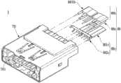
图1A与1B为本发明的插座连接器的立体图。1A and 1B are perspective views of the socket connector of the present invention.
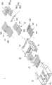
图2A为本发明的插座连接器的分解图。FIG. 2A is an exploded view of the socket connector of the present invention.
图2B为本发明的插座连接器无后塞的分解图。FIG. 2B is an exploded view of the socket connector of the present invention without a back plug.
图2C与2D为本发明的插座连接器的组装流程图。2C and 2D are the assembly flow diagrams of the socket connector of the present invention.
图3A与3B为本发明的第一绝缘座体的立体图。3A and 3B are perspective views of the first insulating base of the present invention.
图4A与4B为本发明的第二绝缘座体的立体图。4A and 4B are perspective views of the second insulating base of the present invention.
图5为本发明的后塞的立体图。Fig. 5 is a perspective view of the back plug of the present invention.
图6为本发明的接地片的立体图。Fig. 6 is a perspective view of the ground sheet of the present invention.
图7为本发明的插座连接器的另一立体图。FIG. 7 is another perspective view of the socket connector of the present invention.
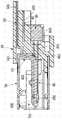
图8为沿着图7中BB线的剖视图。FIG. 8 is a cross-sectional view along line BB in FIG. 7 .
图9为本发明的插座连接器另一实施例的立体图。FIG. 9 is a perspective view of another embodiment of the socket connector of the present invention.
图10为沿着图9中B’B’线的剖视图。Fig. 10 is a sectional view along line B'B' in Fig. 9 .
图中各附图标记说明如下:The reference signs in the figure are explained as follows:
插座连接器 1、1’ 第一绝缘座体 10
第一收容槽 103 第二焊接部 503The
第二收容槽 104 第三导电端子 60The
第三收容槽 105 第三安装部 601The
第二绝缘座体 20 第三接触部 602The second
延伸部 22 第三焊接部 603
中央部 24 金属壳体 70
第一端子槽 201 收容空间 701
第二端子槽 202 传输线 80Second
第三端子槽 203 第一线缆组 80aThe third
后塞 30 第二线缆组 80b
凹槽 301 内部线组 801bGroove 301 Internal wire set 801b
卡固孔 302 第三线缆组 80cFastening hole 302 The
第一导电端子 40 内部线组 801cFirst conductive terminal 40 Internal wire set 801c
第一安装部 401 接地片 802cThe
第一接触部 402 本体 8021cThe
第一焊接部 403 固定部 8022cThe
第二导电端子 50 焊接脚 8023cSecond conductive terminal 50
第二安装部 501 凸部 100
第二接触部 502
具体实施方式Detailed ways
下面结合附图和优选实施例对本发明作进一步的描述,但本发明的实施方式不限于此。The present invention will be further described below with reference to the accompanying drawings and preferred embodiments, but the embodiments of the present invention are not limited thereto.
请参考图1A至2A。本发明的插座连接器1包括一第一绝缘座体10、一第二绝缘座体20、数个第一导电端子40、数个第二导电端子50及数个第三导电端子60。Please refer to Figures 1A to 2A. The
请参考图3A与3B。第一绝缘座体10具有数个第一收容槽103、数个第二收容槽104及数个第三收容槽105。Please refer to FIGS. 3A and 3B . The first insulating
第二绝缘座体20的一端部(未标示)呈阶梯状。较佳的,第二绝缘座体20具有至少一延伸部22、一中央部24及一后塞30。请参考图4A与4B。第二绝缘座体20的中央部24可收容后塞30以形成一阶梯状的结构,如图1B所示。在本实施例中,第二绝缘座体20具有一对延伸部22分别凸设于中央部24的两侧,以利于收容第一绝缘座体10。中央部24并具有数个第一端子槽201分别连通于上述第一收容槽103、数个第二端子槽202分别连通于上述第二收容槽104及数个第三端子槽203分别连通于上述第三收容槽105。One end (not shown) of the second insulating
请参考图5,后塞30具有数个凹槽301及至少一卡固孔302。凹槽301分别连通于上述第三端子槽203。Please refer to FIG. 5 , the
上述第一导电端子40分别收容于上述第一收容槽103及上述第一端子槽201。上述第一导电端子40可向下兼容USB 2.0的传输线。如图2A所示,上述第一导电端子40包括一对第一差动信号端子(未标示)、一电源线(未标示)、及一接地线(未标示)。每一第一导电端子40具有一第一安装部401、连接于第一安装部401一端的一第一接触部402、及连接于第一安装部401另一端的一第一焊接部403。上述第一焊接部403分别收容并暴露于中央部24的上述第一端子槽201。The first
上述第二导电端子50分别收容于上述第二收容槽104及上述第二端子槽202。上述第二导电端子50及上述第一导电端子40可共同用于连接USB 3.0的传输线。如图2A所示,上述第二导电端子50包括一对第二差动信号端子(未标示)、一对第三差动信号端子(未标示)、及一接地线(未标示)。每一第二导电端子50具有一第二安装部501、连接于第二安装部501一端的一第二接触部502及连接于第二安装部501另一端的一第二焊接部503。上述第二焊接部503分别收容并暴露于中央部24的上述第二端子槽202。The second
上述第三导电端子60分别收容于上述第三收容槽105、上述第三端子槽203及凹槽301。上述第三导电端子60可用于连接SATA的传输线。如图2A所示,上述第三导电端子60包括一对第四差动信号端子(未标示)、一对第五差动信号端子(未标示)及三接地线(未标示)。每一第三导电端子60具有一第三安装部601、连接于第三安装部601一端的一第三接触部602及连接于第三安装部601另一端的一第三焊接部603。上述第三焊接部603分别收容并暴露于后塞30的上述凹槽301。插座连接器1更包括一金属外壳70。金属外壳70具有一收容空间701用于收容第一绝缘座体10、第二绝缘座体20、上述第一导电端子40、上述第二导电端子50及上述第三导电端子60。The third
如图1B与8所示,上述第一导电端子40、上述第二导电端子50及上述第三导电端子60暴露于第二绝缘座体20的呈阶梯状的端部。具体说,上述第一焊接部403与上述第三焊接部603分别朝同一个方向暴露于上述第一端子槽201与上述凹槽301,而上述第二焊接部503朝反方向暴露于上述第二端子槽202。As shown in FIGS. 1B and 8 , the first
在另一实施例中,如图9与10所示,插座连接器1’可更具有一凸部100设置于中央部24远离第一绝缘座体10的一端。上述第二焊接部503暴露于凸部100。如此,上述第一焊接部403、上述第二焊接部503及上述第三焊接部603分别朝同一个方向暴露于上述第一端子槽201、凸部100及凹槽301。In another embodiment, as shown in FIGS. 9 and 10 , the receptacle connector 1' may further have a protruding
在另一实施例中,后塞30亦可省略,如图2B所示。在无后塞30的情况下,上述第一焊接部403分别暴露于上述第一端子槽201、上述第二焊接部503分别暴露于上述第二端子槽202及上述第三焊接部603分别收容于上述第三端子槽203并凸设于第二绝缘座体20。In another embodiment, the
上述第一导电端子40、上述第二导电端子50及上述第三导电端子60可焊接于一传输线80。传输线80包括一第一线缆组80a、一第二线缆组80b及一第三线缆组80c。以下将对每一种线缆组做具体的描述。The first
第一线缆组80a具有一对第一信号线(未标示)、一第一接地线(未标示)、及一第一电源线(未标示)。上述第一信号线、第一接地线、及第一电源线分别焊接于上述第一焊接部403。The first cable set 80a has a pair of first signal lines (not marked), a first ground line (not marked), and a first power line (not marked). The first signal line, the first ground line, and the first power line are respectively welded to the
第二线缆组80b具有一对内部线组801b。该每一内部线组801b具有一对第二信号线(未标示)、一第二接地线(未标示)、及一屏蔽层(未标示)。屏蔽层包覆上述第二信号线及第二接地线。上述第二接地线邻近设置并焊接于同一个第二焊接部503。上述第二信号线分别焊接于相对的第二焊接部503。The
第三线缆组80c具有一对内部线组801c及一接地片802c。该每一内部线组801c具有一对第三信号线(未标示)、一第三接地线(未标示)、及一屏蔽层(未标示)。屏蔽层包覆上述第三信号线及第三接地线。关于接地片802c的结构特征,请参考图6。接地片802c具有一本体8021c、至少一固定部8022c及数个焊接脚8023c。固定部8022c设置于本体8021c的一端。固定部8022c可卡固于后塞30的卡固孔302,以利于将接地片802c连接至后塞30。本发明的接地片802c具有三根焊接脚8023c。每一根焊接脚8023c垂直并弯折延伸于本体8021c的一侧。上述第三信号线、上述第三接地线及上述焊接脚8023c分别焊接于相对的第三焊接部603。如图7所示,两根焊接脚8023c分别与一第三接地线邻近设置并焊接于同一个第三焊接部603。The third cable set 80c has a pair of inner wire sets 801c and a
本发明亦提供插座连接器1的组装方法。请参考图2C。首先,利用埋入射出(insert molding)的方式,设置上述第二导电端子50于第一绝缘座体10。组装者亦可先设置上述第三导电端子60于第一绝缘座体10,如图2D所示。The invention also provides an assembly method of the
以下的说明是根据先设置上述第二导电端子50的组装方法,请再参考图2C。当上述第二导电端子50已设置于第一绝缘座体10后,收容第一绝缘座体10于第二绝缘座体20的延伸部22(如箭头A所示)。接着,设置上述第一导电端子40及上述第三导电端子60于第二绝缘座体20。最后,将第一绝缘座体10、第二绝缘座体20、上述第一导电端子40、上述第二导电端子50及上述第三导电端子60收容于金属外壳70。接着,将暴露于第一端子槽201的第一焊接部403、第二端子槽202的第二焊接部503及凹槽301的第三焊接部603焊接于传输线80。The following description is based on the assembly method of disposing the above-mentioned second
本发明的插座连接器1具有与线缆80彼此连接的功能。因此,插座连接器1可移动的设置于一工作平面,以利于使用者的需要。The
以上结合最佳实施例对本发明进行了描述,但本发明并不局限于以上揭示的实施例,而应当涵盖各种根据本发明的本质进行的修改、等效组合。The present invention has been described above in conjunction with the best embodiments, but the present invention is not limited to the above-disclosed embodiments, but should cover various modifications and equivalent combinations made according to the essence of the present invention.
Claims (10)
Translated fromChineseApplications Claiming Priority (2)
| Application Number | Priority Date | Filing Date | Title |
|---|---|---|---|
| US201261583218P | 2012-01-05 | 2012-01-05 | |
| US61/583218 | 2012-01-05 |
Publications (1)
| Publication Number | Publication Date |
|---|---|
| CN103647172Atrue CN103647172A (en) | 2014-03-19 |
Family
ID=47778863
Family Applications (2)
| Application Number | Title | Priority Date | Filing Date |
|---|---|---|---|
| CN201210313798.6APendingCN103647172A (en) | 2012-01-05 | 2012-08-29 | Socket connector and assembling method thereof |
| CN2012204358924UExpired - Fee RelatedCN202772315U (en) | 2012-01-05 | 2012-08-29 | Socket connector |
Family Applications After (1)
| Application Number | Title | Priority Date | Filing Date |
|---|---|---|---|
| CN2012204358924UExpired - Fee RelatedCN202772315U (en) | 2012-01-05 | 2012-08-29 | Socket connector |
Country Status (3)
| Country | Link |
|---|---|
| US (1) | US8801470B2 (en) |
| CN (2) | CN103647172A (en) |
| TW (2) | TW201334323A (en) |
Cited By (13)
| Publication number | Priority date | Publication date | Assignee | Title |
|---|---|---|---|---|
| CN104158044A (en)* | 2014-07-16 | 2014-11-19 | 惠州市和宏电线电缆有限公司 | Manufacturing technique for USB connector |
| CN105281148A (en)* | 2014-07-04 | 2016-01-27 | 富士康(昆山)电脑接插件有限公司 | Socket connector |
| CN105414786A (en)* | 2015-12-11 | 2016-03-23 | 东莞市瀛通电线有限公司 | Plug-in welding process of audio pin and earphone wire |
| CN105428852A (en)* | 2015-12-11 | 2016-03-23 | 东莞市瀛通电线有限公司 | Audio pins with mounted PCB |
| US9843148B2 (en) | 2013-07-19 | 2017-12-12 | Foxconn Interconnect Technology Limited | Flippable electrical connector |
| US9905944B2 (en) | 2013-07-19 | 2018-02-27 | Foxconn Interconnect Technology Limited | Flippable electrical connector |
| US9912111B2 (en) | 2013-07-19 | 2018-03-06 | Foxconn Interconnect Technology Limited | Flippable electrical connector |
| US9997853B2 (en) | 2013-07-19 | 2018-06-12 | Foxconn Interconnect Technology Limited | Flippable electrical connector |
| US10158197B2 (en) | 2013-07-19 | 2018-12-18 | Foxconn Interconnect Technology Limited | Flippable electrical connector |
| US10170870B2 (en) | 2013-07-19 | 2019-01-01 | Foxconn Interconnect Technology Limited | Flippable electrical connector |
| US10693261B2 (en) | 2013-07-19 | 2020-06-23 | Foxconn Interconnect Technology Limited | Flippable electrical connector |
| US10720734B2 (en) | 2013-07-19 | 2020-07-21 | Foxconn Interconnect Technology Limited | Flippable electrical connector |
| US10826255B2 (en) | 2013-07-19 | 2020-11-03 | Foxconn Interconnect Technology Limited | Flippable electrical connector |
Families Citing this family (9)
| Publication number | Priority date | Publication date | Assignee | Title |
|---|---|---|---|---|
| TWM452515U (en)* | 2012-06-27 | 2013-05-01 | Advanced Connectek Inc | Connector structure capable of reducing near end crosstalk |
| TWM445798U (en)* | 2012-07-02 | 2013-01-21 | Nai-Chien Chang | Transmission line having dual-contact type connector |
| CN202772376U (en)* | 2012-08-29 | 2013-03-06 | 泰科电子(上海)有限公司 | Connector |
| CN103972670A (en)* | 2013-02-04 | 2014-08-06 | 富士康(昆山)电脑接插件有限公司 | Cable connector subassembly |
| CN104425946B (en)* | 2013-09-06 | 2017-08-25 | 富士康(昆山)电脑接插件有限公司 | Electric connector |
| TWM476384U (en)* | 2013-10-18 | 2014-04-11 | Advanced Connectek Inc | Receptacle of electrical connector |
| TWM517433U (en)* | 2015-11-24 | 2016-02-11 | 正崴精密工業股份有限公司 | Electrical connector and contact thereof |
| CN106099618B (en)* | 2016-06-17 | 2018-08-28 | 东莞昆嘉电子有限公司 | Production and assembly method of USB Type-C receptacle connector |
| CN107453109B (en)* | 2016-08-30 | 2019-10-01 | 番禺得意精密电子工业有限公司 | Electric connector |
Citations (3)
| Publication number | Priority date | Publication date | Assignee | Title |
|---|---|---|---|---|
| US5421735A (en)* | 1993-01-21 | 1995-06-06 | Molex Incorporated | Modular coaxial cable connector |
| CN101425650A (en)* | 2007-11-02 | 2009-05-06 | 富士康(昆山)电脑接插件有限公司 | Cable assembly with improved cable retention |
| CN201699197U (en)* | 2010-06-11 | 2011-01-05 | 莫列斯公司 | Electric connector |
Family Cites Families (13)
| Publication number | Priority date | Publication date | Assignee | Title |
|---|---|---|---|---|
| US7625243B2 (en) | 2007-06-13 | 2009-12-01 | Hon Hai Precision Ind. Co., Ltd. | Extension to version 2.0 universal serial bus connector with improved contact arrangement |
| TWM357748U (en) | 2007-10-29 | 2009-05-21 | Hon Hai Prec Ind Co Ltd | Electrical connector |
| TWM364331U (en)* | 2009-02-23 | 2009-09-01 | Hon Hai Prec Ind Co Ltd | Electrical connector |
| US7988495B2 (en) | 2009-11-25 | 2011-08-02 | Dnova Corporation | Connector |
| CN101710658B (en)* | 2009-12-16 | 2012-06-13 | 番禺得意精密电子工业有限公司 | Electric connector |
| TWM391203U (en) | 2010-04-21 | 2010-10-21 | Advanced Connectek Inc | Socket connector suitable for using in transmission line |
| US7938659B1 (en)* | 2010-06-29 | 2011-05-10 | Shenzhen Oversea Win Technology Co., Ltd. | Compound connector plug |
| TWM394623U (en) | 2010-07-26 | 2010-12-11 | Hung Ta H T Entpr Co Ltd | Electrical connector |
| US8323057B2 (en)* | 2010-08-13 | 2012-12-04 | Molex Incorporated | Receptacle connector |
| TWM406299U (en) | 2010-11-24 | 2011-06-21 | Shenzhen Oversea Win Technology Co Ltd | Compound female connector |
| CN102544805B (en)* | 2010-12-16 | 2014-12-03 | 富士康(昆山)电脑接插件有限公司 | Cable connector assembly |
| CN102570091B (en)* | 2010-12-16 | 2014-12-03 | 富士康(昆山)电脑接插件有限公司 | Cable connector component |
| TWM406842U (en) | 2011-01-10 | 2011-07-01 | Suyin Corp | Improved structure of electrical connector |
- 2012
- 2012-08-29TWTW101131419Apatent/TW201334323A/enunknown
- 2012-08-29CNCN201210313798.6Apatent/CN103647172A/enactivePending
- 2012-08-29CNCN2012204358924Upatent/CN202772315U/ennot_activeExpired - Fee Related
- 2012-08-29TWTW101216621Upatent/TWM453258U/ennot_activeIP Right Cessation
- 2012-10-31USUS13/664,423patent/US8801470B2/ennot_activeExpired - Fee Related
Patent Citations (3)
| Publication number | Priority date | Publication date | Assignee | Title |
|---|---|---|---|---|
| US5421735A (en)* | 1993-01-21 | 1995-06-06 | Molex Incorporated | Modular coaxial cable connector |
| CN101425650A (en)* | 2007-11-02 | 2009-05-06 | 富士康(昆山)电脑接插件有限公司 | Cable assembly with improved cable retention |
| CN201699197U (en)* | 2010-06-11 | 2011-01-05 | 莫列斯公司 | Electric connector |
Cited By (17)
| Publication number | Priority date | Publication date | Assignee | Title |
|---|---|---|---|---|
| US10312646B2 (en) | 2013-07-19 | 2019-06-04 | Foxconn Interconnect Technology Limited | Flippable electrical connector |
| US9997853B2 (en) | 2013-07-19 | 2018-06-12 | Foxconn Interconnect Technology Limited | Flippable electrical connector |
| US10826255B2 (en) | 2013-07-19 | 2020-11-03 | Foxconn Interconnect Technology Limited | Flippable electrical connector |
| US10720734B2 (en) | 2013-07-19 | 2020-07-21 | Foxconn Interconnect Technology Limited | Flippable electrical connector |
| US9843148B2 (en) | 2013-07-19 | 2017-12-12 | Foxconn Interconnect Technology Limited | Flippable electrical connector |
| US9905944B2 (en) | 2013-07-19 | 2018-02-27 | Foxconn Interconnect Technology Limited | Flippable electrical connector |
| US10693261B2 (en) | 2013-07-19 | 2020-06-23 | Foxconn Interconnect Technology Limited | Flippable electrical connector |
| US9912111B2 (en) | 2013-07-19 | 2018-03-06 | Foxconn Interconnect Technology Limited | Flippable electrical connector |
| US10170870B2 (en) | 2013-07-19 | 2019-01-01 | Foxconn Interconnect Technology Limited | Flippable electrical connector |
| US10158197B2 (en) | 2013-07-19 | 2018-12-18 | Foxconn Interconnect Technology Limited | Flippable electrical connector |
| CN105281148A (en)* | 2014-07-04 | 2016-01-27 | 富士康(昆山)电脑接插件有限公司 | Socket connector |
| TWI675514B (en)* | 2014-07-04 | 2019-10-21 | 英屬開曼群島商鴻騰精密科技股份有限公司 | Receptacle connector |
| CN105281148B (en)* | 2014-07-04 | 2018-03-06 | 富士康(昆山)电脑接插件有限公司 | Socket connector |
| CN104158044B (en)* | 2014-07-16 | 2018-03-23 | 惠州市和宏电线电缆有限公司 | A kind of manufacturing process of USB connector |
| CN104158044A (en)* | 2014-07-16 | 2014-11-19 | 惠州市和宏电线电缆有限公司 | Manufacturing technique for USB connector |
| CN105428852A (en)* | 2015-12-11 | 2016-03-23 | 东莞市瀛通电线有限公司 | Audio pins with mounted PCB |
| CN105414786A (en)* | 2015-12-11 | 2016-03-23 | 东莞市瀛通电线有限公司 | Plug-in welding process of audio pin and earphone wire |
Also Published As
| Publication number | Publication date |
|---|---|
| TWM453258U (en) | 2013-05-11 |
| CN202772315U (en) | 2013-03-06 |
| US8801470B2 (en) | 2014-08-12 |
| TW201334323A (en) | 2013-08-16 |
| US20130178105A1 (en) | 2013-07-11 |
Similar Documents
| Publication | Publication Date | Title |
|---|---|---|
| CN103647172A (en) | Socket connector and assembling method thereof | |
| CN201081835Y (en) | Cable connector assembly | |
| TWI593199B (en) | Electrical connector | |
| CN201230069Y (en) | Electric connector | |
| CN101958476B (en) | Cable connector component | |
| CN201887274U (en) | Cable connector component | |
| TWI558006B (en) | First and second connectors mating with each other | |
| US10348010B2 (en) | Cable connector assembly having minimized cable wires size | |
| CN101944192B (en) | Electronic card | |
| TW201330422A (en) | Electrical receptacle and assembling method thereof | |
| CN107093822B (en) | Electric connector | |
| TW201505289A (en) | Electrical connector | |
| CN204651582U (en) | A kind of electric connector and connector assembly | |
| CN201142425Y (en) | electrical connector | |
| CN101615734B (en) | Cable Connector Assembly | |
| CN104218394B (en) | Plug electric connector | |
| CN206148728U (en) | electrical connector | |
| CN201336412Y (en) | Electric connector | |
| CN204376105U (en) | Plug connector | |
| CN202145522U (en) | Plug connector of reinforced assembly type | |
| CN201887202U (en) | Electric connector component | |
| CN107681315B (en) | Electric connector and manufacturing method thereof | |
| CN204156225U (en) | Connectors with an integrated structure of shielding sheet and snap spring arm | |
| TWM451680U (en) | Cable connector assembly | |
| CN204376005U (en) | Plug connector assembly |
Legal Events
| Date | Code | Title | Description |
|---|---|---|---|
| PB01 | Publication | ||
| PB01 | Publication | ||
| C10 | Entry into substantive examination | ||
| SE01 | Entry into force of request for substantive examination | ||
| C02 | Deemed withdrawal of patent application after publication (patent law 2001) | ||
| WD01 | Invention patent application deemed withdrawn after publication | Application publication date:20140319 |