CN103630743A - Method for correcting frequency of heterodyne type frequency spectrum analyzer - Google Patents
Method for correcting frequency of heterodyne type frequency spectrum analyzerDownload PDFInfo
- Publication number
- CN103630743A CN103630743ACN201310690052.1ACN201310690052ACN103630743ACN 103630743 ACN103630743 ACN 103630743ACN 201310690052 ACN201310690052 ACN 201310690052ACN 103630743 ACN103630743 ACN 103630743A
- Authority
- CN
- China
- Prior art keywords
- frequency
- signal
- tuning
- rbw
- local oscillator
- Prior art date
- Legal status (The legal status is an assumption and is not a legal conclusion. Google has not performed a legal analysis and makes no representation as to the accuracy of the status listed.)
- Granted
Links
- 238000001228spectrumMethods0.000titleclaimsabstractdescription49
- 238000000034methodMethods0.000titleclaimsabstractdescription30
- 238000012545processingMethods0.000claimsabstractdescription15
- 230000009466transformationEffects0.000claimsabstractdescription12
- 238000001514detection methodMethods0.000claimsabstractdescription8
- 238000001914filtrationMethods0.000claimsabstractdescription7
- 238000012937correctionMethods0.000claimsdescription13
- FGUUSXIOTUKUDN-IBGZPJMESA-NC1(=CC=CC=C1)N1C2=C(NC([C@H](C1)NC=1OC(=NN=1)C1=CC=CC=C1)=O)C=CC=C2Chemical compoundC1(=CC=CC=C1)N1C2=C(NC([C@H](C1)NC=1OC(=NN=1)C1=CC=CC=C1)=O)C=CC=C2FGUUSXIOTUKUDN-IBGZPJMESA-N0.000claimsdescription8
- 230000008859changeEffects0.000claimsdescription6
- 230000003247decreasing effectEffects0.000claimsdescription3
- 230000006835compressionEffects0.000abstractdescription5
- 238000007906compressionMethods0.000abstractdescription5
- 230000003321amplificationEffects0.000abstractdescription3
- 238000003199nucleic acid amplification methodMethods0.000abstractdescription3
- 230000001131transforming effectEffects0.000abstract1
- 238000010586diagramMethods0.000description3
- 230000008901benefitEffects0.000description2
- 230000005540biological transmissionEffects0.000description2
- 238000013461designMethods0.000description2
- 238000005516engineering processMethods0.000description2
- 238000005259measurementMethods0.000description2
- 230000004044responseEffects0.000description2
- 238000010183spectrum analysisMethods0.000description2
- 230000009286beneficial effectEffects0.000description1
- 238000006243chemical reactionMethods0.000description1
- 230000007812deficiencyEffects0.000description1
- 238000011161developmentMethods0.000description1
- 238000013100final testMethods0.000description1
- 238000004519manufacturing processMethods0.000description1
- 230000009467reductionEffects0.000description1
Images

Landscapes
- Superheterodyne Receivers (AREA)
- Measuring Frequencies, Analyzing Spectra (AREA)
Abstract
Description
Translated fromChinese技术领域technical field
本发明属于信号处理技术领域,更为具体地讲,涉及一种外差式频谱分析仪频率修正的方法。The invention belongs to the technical field of signal processing, and more specifically relates to a method for frequency correction of a heterodyne spectrum analyzer.
背景技术Background technique
频谱分析仪按照工作原理可以划分为扫描式频谱仪和非扫描式频谱仪,扫描式频谱仪主要可分为滤波式和外差式两种。滤波式频谱仪主要采用多通道滤波器频谱仪,也称为并联型滤波器,对于不同的信号频率,采用不同的滤波器进行处理,最后由多任务扫描器将信号传输到屏幕上显示,但是这种频谱仪结构需多组滤波器,资源消耗比较多,成本较高。Spectrum analyzers can be divided into scanning spectrum analyzers and non-scanning spectrum analyzers according to their working principles. Scanning spectrum analyzers can be mainly divided into filter type and heterodyne type. The filter-type spectrum analyzer mainly uses a multi-channel filter spectrum analyzer, also known as a parallel filter. For different signal frequencies, different filters are used for processing, and finally the multi-tasking scanner transmits the signal to the screen for display, but This spectrum analyzer structure requires multiple sets of filters, which consumes a lot of resources and costs a lot.
外差式频谱分析仪可以实现对高频信号进行多级变频,因此扫频式外差频谱仪可以对频率很高的信号进行分析,同时具有分辨率较高,测量速度快,成本较低等优势,从而获得广泛应用。由于近年来数字信号处理技术的不断发展,各种数字芯片的处理速度越来越快,资源越来越丰富,价格越来越低。频谱仪的中频处理技术逐步从模拟中频转向数字中频,与传统的模拟中频相比,数字中频具有稳定性更高,成本更低,更利于生产调试等优点。The heterodyne spectrum analyzer can realize multi-stage frequency conversion of high-frequency signals, so the sweep-type heterodyne spectrum analyzer can analyze high-frequency signals, and has high resolution, fast measurement speed, and low cost. advantage and thus gain wide application. Due to the continuous development of digital signal processing technology in recent years, the processing speed of various digital chips is getting faster and faster, the resources are more and more abundant, and the price is getting lower and lower. The IF processing technology of the spectrum analyzer has gradually shifted from analog IF to digital IF. Compared with traditional analog IF, digital IF has the advantages of higher stability, lower cost, and more conducive to production and debugging.
外差式频谱仪通过混频得到所需要的频点的基本信息,并通过更改本振频率来获得一个频段,扫描就是不断更新本振频率,使得本振信号刚好扫过一个频点,达到测量目的。输入信号首先经过一个衰减器,保证信号输入混频器时处于合适的电平上,从而防止过载、增益压缩和信号的失真,信号通过衰减器之后经过一个低通滤波器,这个地方的低通滤波器的主要作用是:阻止高频信号进入混频器,防止带外信号与本振相混频在中频产生多余的频率响应,接下来,输入信号与来自本振LO的信号相混频,混频后的信号落到中频滤波器IF的通带内,该信号通过滤波器后,进行包括信号的放大或者压缩,包络检波,视频滤波以及显示等处理。扫频发生器在屏幕上产生从左往右的水平移动,同时对本振进行调谐,使本振频率的变化与扫频发生器的斜坡电压成正比。The heterodyne spectrum analyzer obtains the basic information of the required frequency points through frequency mixing, and obtains a frequency band by changing the local oscillator frequency. Scanning is to continuously update the local oscillator frequency, so that the local oscillator signal just sweeps through a frequency point to achieve measurement Purpose. The input signal first passes through an attenuator to ensure that the signal is at an appropriate level when entering the mixer, thereby preventing overload, gain compression, and signal distortion. After the signal passes through the attenuator, it passes through a low-pass filter. The low-pass filter in this place The main function of the filter is to prevent the high-frequency signal from entering the mixer, prevent the out-of-band signal from mixing with the local oscillator to generate redundant frequency response at the intermediate frequency, and then mix the input signal with the signal from the local oscillator LO, The mixed signal falls into the passband of the intermediate frequency filter IF. After passing through the filter, the signal is processed including signal amplification or compression, envelope detection, video filtering and display. The frequency sweep generator moves horizontally from left to right on the screen, and at the same time tunes the local oscillator so that the change of the frequency of the local oscillator is proportional to the slope voltage of the frequency sweep generator.
频谱仪中,混频得到的数字中频信号进入现场可编程门阵列(FPGA,Field-Programmable Gate Array)后,首先对其数字下变频处理,把模数变换器(ADC,Analog to Digital Converter)输出的信号变为零中频的基带信号,同时完成抽取降数率操作。下变频后的基带信号根据RBW的不同,有两种通道处理方案:RBW>10倍fmin时,在FPGA中通过检波算法得到信号的功率谱,这种方法称为滤波器扫描法;RBW≤10倍fmin时,送到数字信号处理(DSP,Digital Signal Processing)中进行快速傅里叶变换(FFT,Fast Fourier Transformation)变换完成谱分析,这种方法称为FFT扫描法,其中fmin为本振LO调谐点能够实现的最小调谐步进,因此,RBW>10倍fmin采用传统的包络检波,视频滤波等处理获得信号的频谱,而在RBW≤10倍fmin时,可采用FFT算法计算信号的频谱In the spectrum analyzer, after the digital intermediate frequency signal obtained by mixing enters the Field Programmable Gate Array (FPGA, Field-Programmable Gate Array), it is first digitally down-converted, and the analog-to-digital converter (ADC, Analog to Digital Converter) is output The signal becomes the baseband signal of zero intermediate frequency, and at the same time, the operation of decimation and reduction rate is completed. There are two channel processing schemes for the down-converted baseband signal according to the RBW: When RBW>10 times fmin , the power spectrum of the signal is obtained through the detection algorithm in the FPGA. This method is called filter scanning method; RBW≤ When fmin is 10 times, it is sent to digital signal processing (DSP, Digital Signal Processing) for fast Fourier transform (FFT, Fast Fourier Transformation) transformation to complete spectrum analysis. This method is called FFT scanning method, where fmin is The smallest tuning step that can be achieved at the LO tuning point of the local oscillator. Therefore, if RBW>10 times fmin, traditional envelope detection, video filtering, etc. are used to obtain the signal spectrum, and when RBW≤10 times fmin , FFT can be used Algorithms to calculate the spectrum of a signal
然而本振LO调谐点的精度有限,当调频步进控制字加1或者减1时,LO调谐点能够实现的最小调谐步进fmin为:
其中,fref为参考源步进,N为本振频率调频精度,调频步进是前端调谐频点变化的最小单位,因此调谐频点的变化并不是任意的,只能以调频步进的整数倍变化,而在两个相邻可调谐频点间的频点是不能实现的,只能量化到误差最小的可调谐频点上,其误差范围为[-0.5fmin,0.5fmin]。因此,当整个系统的分辨率带宽RBW>10倍fmin时,对最终测试结果影响并不是很大;反之RBW≤10倍fmin误差影响就比较明显。Among them, fref is the reference source step, N is the frequency modulation accuracy of the local oscillator frequency, and the frequency modulation step is the smallest unit of the front-end tuning frequency point change, so the tuning frequency point change is not arbitrary, and can only be an integer of the frequency modulation step It can only be quantized to the tunable frequency point with the smallest error, and the error range is [-0.5fmin ,0.5fmin ]. Therefore, when the resolution bandwidth RBW of the whole system is more than 10 times fmin , the influence on the final test result is not very great; otherwise, the influence of RBW≤10 times fmin error is more obvious.
发明内容Contents of the invention
本发明的目的在于克服现有技术的不足,提供一种外差式频谱分析仪频率修正的方法,将记录的调谐频点值和实际发送调谐频点值的差值经FFT变换后转化为数据点的误差进行频谱误差消除,从而提高了频谱精准度。The purpose of the present invention is to overcome the deficiencies of the prior art, to provide a method for frequency correction of a heterodyne spectrum analyzer, the difference between the recorded tuning frequency point value and the actual transmission tuning frequency point value is converted into data after FFT transformation The error of the point is eliminated for the spectrum error, thereby improving the spectrum accuracy.
为实现上述发明目的,本发明一种外差式频谱分析仪频率修正的方法,其特征在于,包括以下步骤:In order to realize the foregoing invention purpose, a method for frequency correction of a heterodyne spectrum analyzer of the present invention is characterized in that, comprising the following steps:
(1)、将射频信号输入到衰减器后,经低通滤波器滤波后输入到混频器;(1) After the RF signal is input to the attenuator, it is filtered by a low-pass filter and then input to the mixer;
(2)、将参考源产生的信号输入到本振LO,再将本振LO的输出信号输入到混频器,当本振LO的调频步进控制字加1或者减1时,所述的本振LO调谐点能够实现的最小调谐步进fmin为:
(3)、将混频器的输出信号输入到中频滤波器滤波,如果滤波后的信号分辨率带宽RBW>10倍fmin时,通过滤波器扫描法对信号进行放大或者压缩、包络检波和视频滤波处理获取到信号频谱;如果滤波后的信号分辨率带宽RBW≤10倍fmin时,通过FFT扫描法,记录下实际所需调谐频点值或者理想调谐频点值fi与实际发送调谐频点值fLO的误差:Δf=fLO-fi,其中,实际发送调谐频点值fLO与最小调谐步进fmin有如下的关系:fLO=Mfmin M∈[1,2N]∩Z,Z表示整数集,再将得到的误差Δf转化为FFT变换后数据点的误差,其中,FFT变换结果中相邻两频点之间的频率间隔为RBW/2,则Δf引起的频率偏移为2Δf/RBW,最后根据Δf为正还是负将FFT变换后的频率序列向右或向左移动round(2Δf/RBW)个点,获取到信号频谱,其中round(·)表示取最接近·的整数。(3) Input the output signal of the mixer to the intermediate frequency filter for filtering. If the filtered signal resolution bandwidth RBW>10 times fmin , the signal is amplified or compressed by the filter scanning method, envelope detection and The signal spectrum is obtained by video filtering processing; if the filtered signal resolution bandwidth RBW≤10 times fmin , record the actual required tuning frequency point value or ideal tuning frequency point value fi and the actual sending tuning by FFT scanning method The error of the frequency point value fLO : Δf=fLO -fi , where the actual transmitted tuning frequency point value fLO has the following relationship with the minimum tuning step fmin : fLO =Mfmin M∈[1,2N ]∩Z, Z represents an integer set, and then convert the obtained error Δf into the error of the data point after FFT transformation, where the frequency interval between two adjacent frequency points in the FFT transformation result is RBW/2, then the error caused by Δf The frequency offset is 2Δf/RBW. Finally, according to whether Δf is positive or negative, the FFT-transformed frequency sequence is moved to the right or left by round(2Δf/RBW) points to obtain the signal spectrum, where round(·) means the most An integer close to .
本发明的发明目的是这样实现的:The purpose of the invention of the present invention is achieved like this:
本发明外差式频谱分析仪频率修正的方法,当信号送入到外差式频谱分析仪通过处理后判断分辨率带宽RBW,如果当RBW>10倍fmin时,通过滤波器扫描法对信号进行放大或者压缩,包络检波,视频滤波处理获取到信号频谱;当RBW≤10倍fmin时,通过FFT扫描法将记录的调谐频点值和实际发送调谐频点值的差值经FFT变换后转化为数据点的误差进行频谱误差消除,从而提高了识别频谱精准度。The method for frequency correction of the heterodyne spectrum analyzer of the present invention, when the signal is sent to the heterodyne spectrum analyzer, the resolution bandwidth RBW is judged after processing, if when RBW>10 times fmin , the signal is scanned by the filter scanning method Perform amplification or compression, envelope detection, and video filter processing to obtain the signal spectrum; when RBW≤10 times fmin , the difference between the recorded tuning frequency point value and the actual sending tuning frequency point value is transformed by FFT through FFT scanning method Finally, the errors converted into data points are eliminated for spectrum errors, thereby improving the accuracy of spectrum identification.
同时,本发明外差式频谱分析仪频率修正的方法还具有以下有益效果:Simultaneously, the method for frequency correction of the heterodyne spectrum analyzer of the present invention also has the following beneficial effects:
外差式频谱分析仪采用滤波器扫描法和FFT扫描法两种方法,能够提高信号的采用效率,节约采用时间,同时在FFT扫描法中通过将记录的调谐频点值和实际发送调谐频点值的差值经FFT变换后转化为数据点的误差进行频谱误差消除,从而提高了频谱精准度。The heterodyne spectrum analyzer adopts two methods of filter scanning method and FFT scanning method, which can improve the efficiency of signal adoption and save the adoption time. At the same time, in the FFT scanning method, the recorded tuning frequency value and the actual transmission tuning frequency point The difference of the value is converted into the error of the data point after FFT transformation, and the spectrum error is eliminated, thereby improving the spectrum accuracy.
附图说明Description of drawings
图1是本发明外差式频谱分析仪频率修正方法的基本原理框图;Fig. 1 is the basic principle block diagram of heterodyne spectrum analyzer frequency correction method of the present invention;
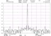
图2是外差式频谱仪修频率正前的频谱图;Fig. 2 is the spectrogram before frequency correction of heterodyne spectrum analyzer;
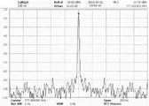
图3是外差式频谱仪频率修正后的频谱图。Fig. 3 is the spectrogram after the frequency correction of the heterodyne spectrum analyzer.
具体实施方式Detailed ways
下面结合附图对本发明的具体实施方式进行描述,以便本领域的技术人员更好地理解本发明。需要特别提醒注意的是,在以下的描述中,当已知功能和设计的详细描述也许会淡化本发明的主要内容时,这些描述在这里将被忽略。Specific embodiments of the present invention will be described below in conjunction with the accompanying drawings, so that those skilled in the art can better understand the present invention. It should be noted that in the following description, when detailed descriptions of known functions and designs may dilute the main content of the present invention, these descriptions will be omitted here.
实施例Example
图1是本发明外差式频谱分析仪频率修正方法的基本原理框图。Fig. 1 is a basic principle block diagram of the frequency correction method of the heterodyne spectrum analyzer of the present invention.
在本实施例中,参考源以振荡器为例,如图1所示,本发明的输入信号首先经过一个衰减器,保证信号输入混频器时处于合适的电平上,从而防止过载、增益压缩和信号的失真,信号通过衰减器之后经过一个低通滤波器,这个地方的低通滤波器的主要作用是:阻止高频信号进入混频器,防止带外信号与本振相混频在中频产生多余的频率响应,接下来,参考振荡器产生的信号输入到本振LO,再将信号输入到混频器,然而本振LO调谐点的精度有限,当调频步进控制字加1或者减1时,所述的本振LO调谐点能够实现的最小调谐步进fmin为:
图2是外差式频谱仪修频率正前的频谱图。Fig. 2 is the spectrogram before frequency correction of the heterodyne spectrum analyzer.
图3是外差式频谱仪频率修正后的频谱图。Fig. 3 is the spectrogram after the frequency correction of the heterodyne spectrum analyzer.
本实施例中,参考源振荡器的步进fref=100MHz,本振调谐精度为24位,则调谐步进最小单位fmin=5.96Hz,调谐误差范围为[-2.98Hz,2.98Hz]。设计中,FFT谱分析对应的RBW档位包括30Hz、10Hz、3Hz和1Hz,在RBW=3Hz时,Δf最大产生2个频点的偏差,而在RBW=1Hz时,Δf最大产生6个频点的偏差,因此需要对FFT结果进行修正,以消除射频本振端调谐误差。假设RBW=1Hz,误差Δf=2.98Hz,那么由Δf所引起的频率偏移点数近似等于6,即3Hz的偏差在频域上映射为6个频点,因此补偿此偏差时,实际要取的频率点应该顺着频率轴往左移动6个点,频率校正前后的频谱图如图2和图3所示。In this embodiment, the step fref of the reference source oscillator is 100 MHz, and the tuning precision of the local oscillator is 24 bits, then the minimum tuning step unit fmin =5.96 Hz, and the tuning error range is [-2.98 Hz, 2.98 Hz]. In the design, the RBW gears corresponding to FFT spectrum analysis include 30Hz, 10Hz, 3Hz and 1Hz. When RBW=3Hz, Δf produces a maximum deviation of 2 frequency points, and when RBW=1Hz, Δf produces a maximum of 6 frequency points. Therefore, the FFT result needs to be corrected to eliminate the tuning error of the radio frequency local oscillator. Assuming RBW=1Hz, error Δf=2.98Hz, then the number of frequency offset points caused by Δf is approximately equal to 6, that is, the deviation of 3Hz is mapped to 6 frequency points in the frequency domain, so when compensating for this deviation, the actual The frequency point should move 6 points to the left along the frequency axis, and the spectrum diagrams before and after frequency correction are shown in Figure 2 and Figure 3.
尽管上面对本发明说明性的具体实施方式进行了描述,以便于本技术领域的技术人员理解本发明,但应该清楚,本发明不限于具体实施方式的范围,对本技术领域的普通技术人员来讲,只要各种变化在所附的权利要求限定和确定的本发明的精神和范围内,这些变化是显而易见的,一切利用本发明构思的发明创造均在保护之列。Although the illustrative specific embodiments of the present invention have been described above, so that those skilled in the art can understand the present invention, it should be clear that the present invention is not limited to the scope of the specific embodiments. For those of ordinary skill in the art, As long as various changes are within the spirit and scope of the present invention defined and determined by the appended claims, these changes are obvious, and all inventions and creations using the concept of the present invention are included in the protection list.
Claims (1)
Translated fromChinese
Priority Applications (1)
| Application Number | Priority Date | Filing Date | Title |
|---|---|---|---|
| CN201310690052.1ACN103630743B (en) | 2013-12-16 | 2013-12-16 | The method of a kind of heterodyne system spectrum analyzer frequency correction |
Applications Claiming Priority (1)
| Application Number | Priority Date | Filing Date | Title |
|---|---|---|---|
| CN201310690052.1ACN103630743B (en) | 2013-12-16 | 2013-12-16 | The method of a kind of heterodyne system spectrum analyzer frequency correction |
Publications (2)
| Publication Number | Publication Date |
|---|---|
| CN103630743Atrue CN103630743A (en) | 2014-03-12 |
| CN103630743B CN103630743B (en) | 2015-12-30 |
Family
ID=50212000
Family Applications (1)
| Application Number | Title | Priority Date | Filing Date |
|---|---|---|---|
| CN201310690052.1AExpired - Fee RelatedCN103630743B (en) | 2013-12-16 | 2013-12-16 | The method of a kind of heterodyne system spectrum analyzer frequency correction |
Country Status (1)
| Country | Link |
|---|---|
| CN (1) | CN103630743B (en) |
Cited By (12)
| Publication number | Priority date | Publication date | Assignee | Title |
|---|---|---|---|---|
| CN104007318A (en)* | 2014-06-17 | 2014-08-27 | 中国科学院电子学研究所 | Signal time-frequency function obtaining method |
| CN104316760A (en)* | 2014-10-10 | 2015-01-28 | 中国电子科技集团公司第四十一研究所 | Dominant frequency signal decision circuit and decision method for microwave frequency counter |
| CN104897959A (en)* | 2014-12-03 | 2015-09-09 | 王澎 | Distributed physical quantity detection method based on frequency spectrum scanning and device thereof |
| CN105652083A (en)* | 2015-12-31 | 2016-06-08 | 上海创远仪器技术股份有限公司 | Circuit structure and method for improving frequency measurement accuracy of superheterodyne spectrum analyzer |
| CN106405235A (en)* | 2016-10-17 | 2017-02-15 | 深圳市鼎阳科技有限公司 | Spectrum analyzer and data processing method thereof |
| CN106405221A (en)* | 2016-08-17 | 2017-02-15 | 中国电子科技集团公司第四十研究所 | Apparatus and method for rapidly and accurately measuring signal frequency and power parameters |
| CN106443122A (en)* | 2016-08-18 | 2017-02-22 | 中国电子科技集团公司第四十研究所 | Broadband large dynamic signal high-precision measurement device and method |
| CN106597343A (en)* | 2016-12-29 | 2017-04-26 | 电子科技大学 | Oscilloscope automatic calibration method based on gain judgment |
| CN106886002A (en)* | 2015-12-15 | 2017-06-23 | 苏州普源精电科技有限公司 | A kind of calibration method of spectrum analyzer |
| CN107576846A (en)* | 2017-08-25 | 2018-01-12 | 中国电子科技集团公司第四十研究所 | A kind of High Precise Frequency Measurement System and method based on sampling frequency-changing technology |
| CN110850344A (en)* | 2018-08-21 | 2020-02-28 | 西门子医疗有限公司 | Method of operating an MRI apparatus |
| CN114966200A (en)* | 2022-04-02 | 2022-08-30 | 成都威频科技有限公司 | Method for realizing RBW and VBW by digital signal processing of frequency spectrograph |
Citations (5)
| Publication number | Priority date | Publication date | Assignee | Title |
|---|---|---|---|---|
| US7397312B2 (en)* | 2005-07-28 | 2008-07-08 | Agilent Technologies, Inc. | Spectrum analyzer and method for correcting frequency errors |
| CN101594128A (en)* | 2009-07-06 | 2009-12-02 | 中国人民解放军国防科学技术大学 | Synchronizing pulse synthesizing method and synchronizing pulse synthesizer for integrated navigation processor |
| US20090310730A1 (en)* | 2008-06-11 | 2009-12-17 | Sergey Zhidkov | Frequency Detector and Phase Locked Loop Having the Same |
| CN103023488A (en)* | 2011-09-22 | 2013-04-03 | 亚旭电子科技(江苏)有限公司 | Frequency correction method and system |
| CN103399203A (en)* | 2013-08-09 | 2013-11-20 | 重庆大学 | High-precision harmonic parameter estimation method based on composite iterative algorithm |
- 2013
- 2013-12-16CNCN201310690052.1Apatent/CN103630743B/ennot_activeExpired - Fee Related
Patent Citations (5)
| Publication number | Priority date | Publication date | Assignee | Title |
|---|---|---|---|---|
| US7397312B2 (en)* | 2005-07-28 | 2008-07-08 | Agilent Technologies, Inc. | Spectrum analyzer and method for correcting frequency errors |
| US20090310730A1 (en)* | 2008-06-11 | 2009-12-17 | Sergey Zhidkov | Frequency Detector and Phase Locked Loop Having the Same |
| CN101594128A (en)* | 2009-07-06 | 2009-12-02 | 中国人民解放军国防科学技术大学 | Synchronizing pulse synthesizing method and synchronizing pulse synthesizer for integrated navigation processor |
| CN103023488A (en)* | 2011-09-22 | 2013-04-03 | 亚旭电子科技(江苏)有限公司 | Frequency correction method and system |
| CN103399203A (en)* | 2013-08-09 | 2013-11-20 | 重庆大学 | High-precision harmonic parameter estimation method based on composite iterative algorithm |
Non-Patent Citations (2)
| Title |
|---|
| 吴也蓓: "频谱分析仪的频率分辨力和测试灵敏度", 《无线通信技术》* |
| 肖晓萍 等: "基于LabVIEW的虚拟频谱分析仪及频域测量误差分析", 《计算机工程与设计》* |
Cited By (18)
| Publication number | Priority date | Publication date | Assignee | Title |
|---|---|---|---|---|
| CN104007318B (en)* | 2014-06-17 | 2016-11-09 | 中国科学院电子学研究所 | The method of obtaining the time-frequency function of the signal |
| CN104007318A (en)* | 2014-06-17 | 2014-08-27 | 中国科学院电子学研究所 | Signal time-frequency function obtaining method |
| CN104316760A (en)* | 2014-10-10 | 2015-01-28 | 中国电子科技集团公司第四十一研究所 | Dominant frequency signal decision circuit and decision method for microwave frequency counter |
| CN104897959A (en)* | 2014-12-03 | 2015-09-09 | 王澎 | Distributed physical quantity detection method based on frequency spectrum scanning and device thereof |
| CN104897959B (en)* | 2014-12-03 | 2017-11-24 | 王澎 | A kind of distributed physical amount detection method and its device based on spectrum scan |
| CN106886002A (en)* | 2015-12-15 | 2017-06-23 | 苏州普源精电科技有限公司 | A kind of calibration method of spectrum analyzer |
| CN105652083A (en)* | 2015-12-31 | 2016-06-08 | 上海创远仪器技术股份有限公司 | Circuit structure and method for improving frequency measurement accuracy of superheterodyne spectrum analyzer |
| CN105652083B (en)* | 2015-12-31 | 2019-03-01 | 上海创远仪器技术股份有限公司 | Improve the circuit structure and method of superhet spectrum analyzer frequency measurement accuracy |
| CN106405221B (en)* | 2016-08-17 | 2019-01-18 | 中国电子科技集团公司第四十一研究所 | A kind of device and method of quick high accuracy measuring signal frequency power parameter |
| CN106405221A (en)* | 2016-08-17 | 2017-02-15 | 中国电子科技集团公司第四十研究所 | Apparatus and method for rapidly and accurately measuring signal frequency and power parameters |
| CN106443122A (en)* | 2016-08-18 | 2017-02-22 | 中国电子科技集团公司第四十研究所 | Broadband large dynamic signal high-precision measurement device and method |
| CN106443122B (en)* | 2016-08-18 | 2020-05-15 | 中国电子科技集团公司第四十一研究所 | High-precision measurement device and method for wide-band large dynamic signal |
| CN106405235A (en)* | 2016-10-17 | 2017-02-15 | 深圳市鼎阳科技有限公司 | Spectrum analyzer and data processing method thereof |
| CN106405235B (en)* | 2016-10-17 | 2019-09-10 | 深圳市鼎阳科技有限公司 | A kind of spectrum analyzer and its data processing method |
| CN106597343A (en)* | 2016-12-29 | 2017-04-26 | 电子科技大学 | Oscilloscope automatic calibration method based on gain judgment |
| CN107576846A (en)* | 2017-08-25 | 2018-01-12 | 中国电子科技集团公司第四十研究所 | A kind of High Precise Frequency Measurement System and method based on sampling frequency-changing technology |
| CN110850344A (en)* | 2018-08-21 | 2020-02-28 | 西门子医疗有限公司 | Method of operating an MRI apparatus |
| CN114966200A (en)* | 2022-04-02 | 2022-08-30 | 成都威频科技有限公司 | Method for realizing RBW and VBW by digital signal processing of frequency spectrograph |
Also Published As
| Publication number | Publication date |
|---|---|
| CN103630743B (en) | 2015-12-30 |
Similar Documents
| Publication | Publication Date | Title |
|---|---|---|
| CN103630743B (en) | The method of a kind of heterodyne system spectrum analyzer frequency correction | |
| CN104316760B (en) | A kind of dominant frequency signal determinating circuit and decision method for being applied to microwave frequency counter | |
| CN104122444B (en) | All-digital IF spectrum analyzer and frequency spectrum analysis method | |
| CN102879643A (en) | Novel spectrum analyzer and method | |
| CN106017669B (en) | A kind of multi-functional reading circuit system of KID detector arrays | |
| CN104635049A (en) | Spectrum analyzer with calibration function | |
| CN109001729B (en) | Real-time calibration method and system for FM continuous wave linearity in terahertz imaging | |
| CN104459317B (en) | A kind of spectrum analyzer that can inhibit image frequency | |
| CN106443122A (en) | Broadband large dynamic signal high-precision measurement device and method | |
| CN104635062A (en) | Environment electromagnetic radiation monitoring system | |
| CN103607215A (en) | Device and method for achieving spread spectrum function of spectrum analyzer | |
| CN106353594B (en) | A kind of fast multiresolution frequency spectrum analysis system and method | |
| CN203798907U (en) | Multi-channel broadband microwave radiometer with self-calibration function | |
| CN106886002A (en) | A kind of calibration method of spectrum analyzer | |
| CN111030765B (en) | A Heterodyne Sweep Spectrum Analysis System That Can Identify Image-Frequency Signals | |
| CN202679376U (en) | Interference signal detection system and antenna | |
| CN118707188B (en) | A signal spectrum monitoring system and method based on Rydberg atoms | |
| CN205017281U (en) | Ultrashort wave pectination spectrum signal produces circuit | |
| CN204272098U (en) | Shortwave frequency conversion channel | |
| CN107885275B (en) | A kind of automatic conditioning device and method of the wide-band intermediate frequency of signal source analyzer | |
| CN113376434A (en) | Frequency spectrum analysis method based on chirp transformation architecture and rapid digital pulse pressure algorithm | |
| CN105471525B (en) | A Four-Channel Compressed Sensing Digital Receiver Signal Processing Method for Vector Network Analyzer | |
| CN110535469B (en) | Signal processing method and device | |
| CN106330353B (en) | Local oscillator phase noise detection method and device and radio remote unit | |
| CN214281386U (en) | Device for realizing test aiming at 5G NR uplink time slot interference |
Legal Events
| Date | Code | Title | Description |
|---|---|---|---|
| PB01 | Publication | ||
| PB01 | Publication | ||
| C10 | Entry into substantive examination | ||
| SE01 | Entry into force of request for substantive examination | ||
| C14 | Grant of patent or utility model | ||
| GR01 | Patent grant | ||
| CF01 | Termination of patent right due to non-payment of annual fee | Granted publication date:20151230 Termination date:20211216 | |
| CF01 | Termination of patent right due to non-payment of annual fee |