CN103603125A - Main nozzle structure of air jet loom and method for accelerating air flow inside main nozzle - Google Patents
Main nozzle structure of air jet loom and method for accelerating air flow inside main nozzleDownload PDFInfo
- Publication number
- CN103603125A CN103603125ACN201310670129.9ACN201310670129ACN103603125ACN 103603125 ACN103603125 ACN 103603125ACN 201310670129 ACN201310670129 ACN 201310670129ACN 103603125 ACN103603125 ACN 103603125A
- Authority
- CN
- China
- Prior art keywords
- nozzle
- air
- group
- core
- main nozzle
- Prior art date
- Legal status (The legal status is an assumption and is not a legal conclusion. Google has not performed a legal analysis and makes no representation as to the accuracy of the status listed.)
- Granted
Links
- 238000000034methodMethods0.000titleclaimsabstractdescription12
- 230000001133accelerationEffects0.000claimsabstractdescription41
- 230000015572biosynthetic processEffects0.000claims1
- 239000007921spraySubstances0.000claims1
- 238000003780insertionMethods0.000abstractdescription15
- 230000037431insertionEffects0.000abstractdescription15
- 230000007423decreaseEffects0.000description2
- 238000010586diagramMethods0.000description2
- 238000012966insertion methodMethods0.000description2
- 230000007812deficiencyEffects0.000description1
- 238000004519manufacturing processMethods0.000description1
- 239000000463materialSubstances0.000description1
- 238000012986modificationMethods0.000description1
- 230000004048modificationEffects0.000description1
Images

Landscapes
- Looms (AREA)
Abstract
Description
Translated fromChinese技术领域technical field
本发明属于织机设计制造技术领域,具体涉及一种喷气织机的主喷嘴结构及主喷嘴内气流加速方法。The invention belongs to the technical field of loom design and manufacture, and in particular relates to a main nozzle structure of an air-jet loom and an airflow acceleration method in the main nozzle.
背景技术Background technique
喷气织机是采用喷射气流牵引纬纱穿越梭口的无梭织机。其利用空气作为引纬介质,以喷射出的压缩气流对纬纱产生摩擦牵引力进行牵引,将纬纱带过梭口,通过喷气产生的射流来达到引纬的目的。该类引纬方式能使织机实现高速、高产。在几种无梭织机中,喷气织机是车速最高的一种,由于引纬方式合理,入纬率较高,运转操作简便安全,具有品种适应性较广、机物料消耗少、效率高、车速高、噪音低等优点,已成为最具发展前途的新型织机之一。喷气织机一分钟一般能够引纬800-1000次,每次引纬时纬纱经过梭口一次。The air-jet loom is a shuttleless loom that uses jet air to pull the weft through the shed. It uses air as the weft insertion medium, and uses the jetted compressed airflow to generate frictional traction on the weft yarn to pull the weft yarn through the shed, and achieve the purpose of weft insertion through the jet generated by the air jet. This type of weft insertion method enables the loom to achieve high speed and high output. Among several shuttleless looms, the air-jet loom is the one with the highest speed. Due to the reasonable weft insertion method, the weft insertion rate is high, the operation is simple and safe, and it has wide variety adaptability, low machine material consumption and high efficiency. , high speed, low noise and other advantages, it has become one of the most promising new looms. Air-jet looms can generally insert weft 800-1000 times in one minute, and the weft yarn passes through the shed once each time weft is inserted.
主喷嘴是喷气织机引纬系统的关键部件,其加速管出口处气流场性质对于引纬质量有着直接影响。目前喷气织机入纬率一般为1600-2000m/min,更高者可达3200m/min,因此,主喷嘴的改进对于高速喷气引纬具有重要意义。The main nozzle is the key component of the weft insertion system of the air-jet loom, and the properties of the airflow field at the exit of the acceleration tube have a direct impact on the weft insertion quality. At present, the weft insertion rate of air-jet looms is generally 1600-2000m/min, and the higher one can reach 3200m/min. Therefore, the improvement of the main nozzle is of great significance for high-speed air-jet weft insertion.
目前,现有的喷气织机实际运行速度一般为750-900r/min,纬纱飞行速度约为100m/s,入纬率为2000m/min。对于主喷嘴而言,其主要技术指标为加速管出口处气流核心区长度以及有效速度区域大小。At present, the actual operating speed of existing air-jet looms is generally 750-900r/min, the flying speed of weft yarn is about 100m/s, and the weft insertion rate is 2000m/min. For the main nozzle, its main technical indicators are the length of the core area of the airflow at the outlet of the accelerator tube and the size of the effective velocity area.
现有技术中主喷嘴采用高压力小流量设计方案,使其在喉部区域获得超音速射流,由此产生负压区,在该负压区的作用下,外界大气携带纬纱经过喷嘴芯内部流道进入主喷嘴加速管,当高速气流经加速管进入大气后,气流速度随距离加速管出口距离的增大而迅速下跌。因此,增长主喷嘴加速管出口处气流核心区以及有效速度区域是急需克服的问题。In the prior art, the main nozzle adopts a high-pressure and low-flow design scheme, so that it can obtain a supersonic jet flow in the throat area, thereby creating a negative pressure zone. Under the action of the negative pressure zone, the outside atmosphere carries the weft yarn through the inner flow of the nozzle core. When the high-speed air flows through the acceleration tube and enters the atmosphere, the air velocity decreases rapidly with the increase of the distance from the exit of the acceleration tube. Therefore, increasing the airflow core area and the effective velocity area at the outlet of the main nozzle accelerator tube is an urgent problem to be overcome.
鉴于以上问题,有必要提出一种新型的主喷嘴结构,以实现加速管出口处气流核心区以及有效速度区域的明显增长,提高主喷嘴的引纬能力。In view of the above problems, it is necessary to propose a new type of main nozzle structure to achieve a significant increase in the core area of the airflow at the exit of the acceleration tube and the effective velocity area, and improve the weft insertion capacity of the main nozzle.
发明内容Contents of the invention
有鉴于此,本发明提供一种喷气织机的主喷嘴结构及主喷嘴内气流加速方法,以实现加速管出口处气流核心区以及有效速度区域的明显增长,提高主喷嘴的引纬能力。In view of this, the present invention provides a main nozzle structure of an air-jet loom and an airflow acceleration method in the main nozzle, so as to achieve a significant increase in the core area of the airflow at the exit of the acceleration tube and the effective velocity area, and improve the weft insertion capacity of the main nozzle.
根据本发明的目的提出了一种喷气织机的主喷嘴结构,所述主喷嘴结构包括首尾依次串联设置的至少两组喷嘴以及设置于所述喷嘴前端的加速管;所述喷嘴包括喷嘴体、位于所述喷嘴体内部的喷嘴芯、以及套设于所述喷嘴芯上的锥形套,后一组喷嘴的喷嘴芯伸入所述前一组喷嘴的喷嘴芯内部,多个喷嘴芯内部流道连通;According to the purpose of the present invention, a main nozzle structure of an air-jet loom is proposed, the main nozzle structure includes at least two groups of nozzles arranged in series from head to tail and an acceleration tube arranged at the front end of the nozzle; the nozzle includes a nozzle body, The nozzle core located inside the nozzle body and the tapered sleeve set on the nozzle core, the nozzle cores of the latter group of nozzles extend into the nozzle cores of the former group of nozzles, and the internal flow of multiple nozzle cores Road connected;
各组所述喷嘴体上对应开设有供气压力入口,所述喷嘴体与喷嘴芯及锥形套之间有与所述供气压力入口连通的气流通道,气流依次经过供气压力入口、气流通道后形成负压,实现气流加速,进入前一组喷嘴的喷嘴芯内部流道,气流加速次数与所述喷嘴组数一致。The nozzle body of each group is correspondingly provided with an air supply pressure inlet, and there is an airflow channel connected with the air supply pressure inlet between the nozzle body, the nozzle core and the tapered sleeve, and the airflow passes through the air supply pressure inlet, the airflow Negative pressure is formed behind the channel to accelerate the airflow, and enter the inner flow channel of the nozzle core of the previous group of nozzles, and the number of airflow accelerations is consistent with the number of nozzle groups.
优选的,所述主喷嘴结构包括两组喷嘴。Preferably, the main nozzle structure includes two groups of nozzles.
优选的,相邻两个所述喷嘴体可拆卸连接。Preferably, two adjacent nozzle bodies are detachably connected.
一种喷气织机主喷嘴内气流加速方法,采用所述的喷气织机的主喷嘴结构,具体步骤如下:A method for accelerating airflow in the main nozzle of an air-jet loom, using the structure of the main nozzle of the air-jet loom, the specific steps are as follows:
(一)、通过供气压力入口向第一组喷嘴内通入空气,空气经喷嘴体与喷嘴芯及锥形套之间的气流通道,形成负压,实现一级加速,进入第二组喷嘴内喷嘴芯的内部流道,使得第一组喷嘴中的空气流向第二组喷嘴内喷嘴芯的内部流道;(1) Air is passed into the first group of nozzles through the air supply pressure inlet, and the air passes through the airflow channel between the nozzle body, the nozzle core and the tapered sleeve to form a negative pressure, realize the first-level acceleration, and enter the second group of nozzles an internal flow passage of the inner nozzle core such that air in the first set of nozzles flows to an internal flow passage of the inner nozzle core of the second set of nozzles;
(二)、通过供气压力入口向第二组喷嘴通入空气,空气经喷嘴体与喷嘴芯及锥形套之间的气流通道,形成负压,实现气流加速,并与第一组喷嘴内加速气流作用,形成二级加速,使得第二组喷嘴中的空气流向第三组喷嘴内喷嘴芯的内部流道;(2) Air is fed into the second group of nozzles through the air supply pressure inlet, and the air passes through the airflow channel between the nozzle body, the nozzle core and the tapered sleeve to form a negative pressure to realize the acceleration of the airflow, and it is connected with the first group of nozzles Accelerate the air flow to form a secondary acceleration, so that the air in the second group of nozzles flows to the inner flow channel of the nozzle core in the third group of nozzles;
(三)、如此循环,最后空气经过多级加速进入加速管。(3) In such a cycle, the air finally enters the acceleration tube through multi-stage acceleration.
与现有技术相比,本发明公开的喷气织机的主喷嘴结构及主喷嘴内气流加速方法的优点是:主喷嘴结构包括首尾依次串接设置的至少两组喷嘴,且每组喷嘴上对应设置有供气压力入口与气流通道,空气可依次经供气压力入口、气流通道进入喷嘴内,并在喷嘴内实现加速,设置多组喷嘴可实现在主喷嘴内的多级加速,以实现加速管出口处气流核心区以及有效速度区域的明显增长,提高主喷嘴的引纬能力。Compared with the prior art, the advantages of the main nozzle structure of the air-jet loom and the airflow acceleration method in the main nozzle disclosed in the present invention are: the main nozzle structure includes at least two groups of nozzles arranged in series from head to tail, and each group of nozzles corresponds to The air supply pressure inlet and the air flow channel are set, the air can enter the nozzle through the air supply pressure inlet and the air flow channel in turn, and accelerate in the nozzle. Setting multiple groups of nozzles can realize multi-stage acceleration in the main nozzle to achieve acceleration The core area of the airflow at the tube outlet and the significant increase in the effective velocity area improve the weft insertion capacity of the main nozzle.
附图说明Description of drawings
为了更清楚地说明本发明实施例或现有技术中的技术方案,下面将对实施例或现有技术描述中所需要使用的附图作简单地介绍,显而易见地,下面描述中的附图仅仅是本发明的一些实施例,对于本领域普通技术人员来讲,在不付出创造性劳动的前提下,还可以根据这些附图获得其他的附图。In order to more clearly illustrate the technical solutions in the embodiments of the present invention or the prior art, the following will briefly introduce the drawings that need to be used in the description of the embodiments or the prior art. Obviously, the accompanying drawings in the following description are only These are some embodiments of the present invention. Those skilled in the art can also obtain other drawings based on these drawings without creative work.
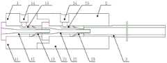
图1为本发明公开的一种喷气织机的主喷嘴结构的示意图。Fig. 1 is a schematic diagram of a main nozzle structure of an air-jet loom disclosed in the present invention.
图2为本发明公开的一种喷气织机的主喷嘴结构的气流流向图。Fig. 2 is an air flow diagram of a main nozzle structure of an air-jet loom disclosed by the present invention.
图中的数字所代表的相应部件或区域的名称:The names of the corresponding parts or areas represented by the numbers in the figure:
1、第一组喷嘴2、第二组喷嘴3、加速管1. The first group of nozzles 2. The second group of
11、第一喷嘴体12、第一喷嘴芯13、第一锥形套14、第一供气压力入口15、第一气流通道11.
21、第二喷嘴体22、第二喷嘴芯23、第二锥形套24、第二供气压力入口25、第二气流通道21.
具体实施方式Detailed ways
现有技术中主喷嘴采用高压力小流量设计方案,使其在喉部区域获得超音速射流,由此产生负压区,在该负压区的作用下,外界大气携带纬纱经过喷嘴芯内部流道进入主喷嘴加速管,当高速气流经加速管进入大气后,气流速度随距离加速管出口距离的增大而迅速下跌。因此,增长主喷嘴加速管出口处气流核心区以及有效速度区域是急需克服的问题。In the prior art, the main nozzle adopts a high-pressure and low-flow design scheme, so that it can obtain a supersonic jet flow in the throat area, thereby creating a negative pressure zone. Under the action of the negative pressure zone, the outside atmosphere carries the weft yarn through the inner flow of the nozzle core. When the high-speed air flows through the acceleration tube and enters the atmosphere, the air velocity decreases rapidly with the increase of the distance from the exit of the acceleration tube. Therefore, increasing the airflow core area and the effective velocity area at the outlet of the main nozzle accelerator tube is an urgent problem to be overcome.
本发明针对现有技术中的不足,提供了一种喷气织机的主喷嘴结构及主喷嘴内气流加速方法,以实现加速管出口处气流核心区以及有效速度区域的明显增长,提高主喷嘴的引纬能力。Aiming at the deficiencies in the prior art, the present invention provides a main nozzle structure of an air-jet loom and a method for accelerating the air flow in the main nozzle, so as to realize the obvious increase of the core area of the air flow at the outlet of the acceleration tube and the effective velocity area, and improve the airflow of the main nozzle. Weft insertion capability.
下面将通过具体实施方式对本发明的技术方案进行清楚、完整地描述。显然,所描述的实施例仅仅是本发明一部分实施例,而不是全部的实施例。基于本发明中的实施例,本领域普通技术人员在没有作出创造性劳动前提下所获得的所有其他实施例,都属于本发明保护的范围。The technical solutions of the present invention will be clearly and completely described below through specific embodiments. Apparently, the described embodiments are only some of the embodiments of the present invention, but not all of them. Based on the embodiments of the present invention, all other embodiments obtained by persons of ordinary skill in the art without creative efforts fall within the protection scope of the present invention.
一种喷气织机的主喷嘴结构,主喷嘴结构包括首尾依次串联设置的至少两组喷嘴以及设置于喷嘴前端的加速管3;喷嘴包括喷嘴体、位于喷嘴体内部的喷嘴芯、以及套设于喷嘴芯上的锥形套,后一组喷嘴的喷嘴芯伸入前一组喷嘴的喷嘴芯内部,使得多个喷嘴芯内部流道连通。A main nozzle structure of an air-jet loom, the main nozzle structure includes at least two groups of nozzles arranged in series from head to tail and an
各喷嘴体上对应开设有供气压力入口,喷嘴体与喷嘴芯及锥形套之间有与供气压力入口连通的气流通道,气流依次经过供气压力入口、气流通道后形成负压,实现气流加速,进入前一组喷嘴的喷嘴芯内部流道,所述气流加速次数与喷嘴组数一致。设置多组喷嘴可实现在加速管内的多级加速,以实现加速管出口处气流核心区以及有效速度区域的明显增长,提高主喷嘴的引纬能力。喷嘴组数具体根据使用需要而定,在此不做限制。Each nozzle body is correspondingly provided with an air supply pressure inlet, and there is an airflow channel connected with the air supply pressure inlet between the nozzle body, the nozzle core and the tapered sleeve, and the airflow sequentially passes through the air supply pressure inlet and the airflow channel to form a negative pressure, realizing The airflow accelerates and enters the nozzle core internal flow channel of the previous group of nozzles, and the number of times the airflow accelerates is consistent with the number of nozzle groups. Setting multiple groups of nozzles can achieve multi-stage acceleration in the acceleration tube, so as to realize the obvious increase of the core area of the airflow at the exit of the acceleration tube and the effective velocity area, and improve the weft insertion capacity of the main nozzle. The number of nozzle groups is determined according to the needs of use, and is not limited here.
相邻两个喷嘴体可拆卸设置。便于拆装,连接方式可为卡接或对接后采用螺栓固定,或采用螺纹旋接方式固定等,具体不做限制。Two adjacent nozzle bodies are detachably arranged. It is easy to disassemble and assemble, and the connection method can be clamped or docked, fixed by bolts, or fixed by threaded connection, etc., there is no specific limit.
如图1、2所示,主喷嘴结构包括两组喷嘴。As shown in Figures 1 and 2, the main nozzle structure includes two groups of nozzles.
第一组喷嘴1包括第一喷嘴体11、位于第一喷嘴体11内部的第一喷嘴芯12、套设于第一喷嘴芯12上的第一锥形套13,第一喷嘴体11上开设有第一供气压力入口14,第一喷嘴体11与第一喷嘴芯12及第一锥形套13之间有与第一供气压力入口14连通的第一气流通道15,气流经过第一供气压力入口14、第一气流通道15后形成负压,实现气流加速,进入第二喷嘴芯22内部流道,实现气流在第一组喷嘴1内的一级加速。The first group of nozzles 1 includes a
第二组喷嘴2包括第二喷嘴体21、位于第二组喷嘴体21内部的第二喷嘴芯22、套设于第二喷嘴芯22上的第二锥形套23,第二喷嘴体21上开设有第二供气压力入口24,第二喷嘴体21与第二喷嘴芯22及第二锥形套23之间有与第二供气压力入口24连通的第二气流通道25。与第一组喷嘴原理相同,气流经过第二供气压力入口24、第一气流通道25后形成负压,实现气流加速,并与第一组喷嘴1内加速气流作用,形成二级加速。The second group of nozzles 2 includes a
此外,在出口处,气流性质在一定的供气压力分配下会得到一定的改善,加速管出口处气流核心区以及有效速度区域会有明显增长。具体供气压力大小根据使用需要而定,在此不做限制。In addition, at the outlet, the airflow properties will be improved under a certain air supply pressure distribution, and the airflow core area and effective velocity area at the outlet of the accelerator tube will increase significantly. The specific air supply pressure depends on the needs of use, and there is no limitation here.
一种喷气织机主喷嘴内气流加速方法,采用喷气织机的主喷嘴结构,具体步骤如下:A method for accelerating air flow in the main nozzle of an air-jet loom, using the structure of the main nozzle of the air-jet loom, and the specific steps are as follows:
(一)、通过供气压力入口向第一组喷嘴内通入空气,空气经喷嘴体与喷嘴芯及锥形套之间的气流通道,形成负压,实现一级加速,进入第二喷嘴芯内部流道,使得第一组喷嘴中的空气流向第二喷嘴芯的内部流道;(1) Air is introduced into the first group of nozzles through the air supply pressure inlet, and the air passes through the airflow channel between the nozzle body, the nozzle core and the tapered sleeve to form a negative pressure to achieve a first-level acceleration and enter the second nozzle core an internal flow channel such that air in the first set of nozzles flows to the internal flow channel of the second nozzle core;
(二)、通过供气压力入口向第二组喷嘴通入空气,空气经喷嘴体与喷嘴芯及锥形套之间的气流通道,形成负压,实现气流加速,并与第一组喷嘴内加速气流作用,形成二级加速,使得第二组喷嘴中的空气流向第三喷嘴芯的内部流道;(2) Air is fed into the second group of nozzles through the air supply pressure inlet, and the air passes through the airflow channel between the nozzle body, the nozzle core and the tapered sleeve to form a negative pressure to realize the acceleration of the airflow, and it is connected with the first group of nozzles Accelerate the air flow to form a secondary acceleration, so that the air in the second group of nozzles flows to the inner channel of the third nozzle core;
(三)、如此循环,最后空气经过多级加速进入加速管。(3) In such a cycle, the air finally enters the acceleration tube through multi-stage acceleration.
本发明公开了一种喷气织机的主喷嘴结构及主喷嘴内气流加速方法,主喷嘴结构包括首尾依次串接设置的至少两组喷嘴,每组喷嘴上对应开设有供气压力入口与气流通道,空气可依次经供气压力入口、气流通道进入喷嘴内,并在喷嘴内实现加速,设置多组喷嘴可实现在加速管内的多级加速,以实现加速管出口处气流核心区以及有效速度区域的明显增长,提高主喷嘴的引纬能力。The invention discloses a main nozzle structure of an air-jet loom and a method for accelerating air flow in the main nozzle. The main nozzle structure includes at least two groups of nozzles arranged in series from head to tail, and each group of nozzles is correspondingly provided with an air supply pressure inlet and an air flow channel. , the air can enter the nozzle through the air supply pressure inlet and the air flow channel in turn, and accelerate in the nozzle. Setting multiple groups of nozzles can realize multi-stage acceleration in the acceleration tube, so as to realize the core area of the air flow at the exit of the acceleration tube and the effective velocity area Significant growth, improve the weft insertion capacity of the main nozzle.
对所公开的实施例的上述说明,使本领域专业技术人员能够实现或使用本发明。对这些实施例的多种修改对本领域的专业技术人员来说将是显而易见的,本文中所定义的一般原理可以在不脱离本发明的精神或范围的情况下,在其它实施例中实现。因此,本发明将不会被限制于本文所示的这些实施例,而是要符合与本文所公开的原理和新颖特点相一致的最宽的范围。The above description of the disclosed embodiments is provided to enable any person skilled in the art to make or use the invention. Various modifications to these embodiments will be readily apparent to those skilled in the art, and the general principles defined herein may be implemented in other embodiments without departing from the spirit or scope of the invention. Therefore, the present invention will not be limited to the embodiments shown herein, but is to be accorded the widest scope consistent with the principles and novel features disclosed herein.
Claims (4)
Priority Applications (1)
| Application Number | Priority Date | Filing Date | Title |
|---|---|---|---|
| CN201310670129.9ACN103603125B (en) | 2013-12-10 | 2013-12-10 | Air-flow accelerated method in a kind of main nozzle structure of air-jet loom and main burner |
Applications Claiming Priority (1)
| Application Number | Priority Date | Filing Date | Title |
|---|---|---|---|
| CN201310670129.9ACN103603125B (en) | 2013-12-10 | 2013-12-10 | Air-flow accelerated method in a kind of main nozzle structure of air-jet loom and main burner |
Publications (2)
| Publication Number | Publication Date |
|---|---|
| CN103603125Atrue CN103603125A (en) | 2014-02-26 |
| CN103603125B CN103603125B (en) | 2015-10-28 |
Family
ID=50121383
Family Applications (1)
| Application Number | Title | Priority Date | Filing Date |
|---|---|---|---|
| CN201310670129.9AExpired - Fee RelatedCN103603125B (en) | 2013-12-10 | 2013-12-10 | Air-flow accelerated method in a kind of main nozzle structure of air-jet loom and main burner |
Country Status (1)
| Country | Link |
|---|---|
| CN (1) | CN103603125B (en) |
Cited By (4)
| Publication number | Priority date | Publication date | Assignee | Title |
|---|---|---|---|---|
| CN104389089A (en)* | 2014-10-30 | 2015-03-04 | 东华大学 | Main nozzle structure of air jet loom for producing elastic denim and weft insertion method thereof |
| CN106312837A (en)* | 2016-09-22 | 2017-01-11 | 武汉大学 | Post-mixing type abrasive water jet nozzle based on annular jet |
| CN106743674A (en)* | 2017-02-28 | 2017-05-31 | 中国空气动力研究与发展中心高速空气动力研究所 | A kind of device that solid powder is sent into high velocity air |
| CN115522304A (en)* | 2022-10-26 | 2022-12-27 | 南通大学 | Main nozzle capable of accelerating air jet loom |
Citations (9)
| Publication number | Priority date | Publication date | Assignee | Title |
|---|---|---|---|---|
| CH610366A5 (en)* | 1976-09-27 | 1979-04-12 | Rueti Ag Maschf | Device for inserting weft threads into a shed |
| GB2012322A (en)* | 1978-01-06 | 1979-07-25 | Nissan Motor | Weft picking device of air jet type weaving loom |
| US4367772A (en)* | 1979-08-08 | 1983-01-11 | Sulzer Brothers Limited | Nozzle assembly for a weaving machine |
| US4433706A (en)* | 1980-10-15 | 1984-02-28 | Nissan Motor Co., Ltd. | Weft inserting nozzle of an air jet type weaving loom |
| JP2524766B2 (en)* | 1987-08-26 | 1996-08-14 | 津田駒工業株式会社 | Thread guide device |
| CN202107856U (en)* | 2011-06-20 | 2012-01-11 | 苏州大学 | Main nozzle of air-jet loom used under high air supplying pressure |
| CN102493104A (en)* | 2011-12-15 | 2012-06-13 | 江苏万工科技集团有限公司 | Double-pressure-supply main nozzle, and air supply system thereof |
| CN102677371A (en)* | 2012-06-12 | 2012-09-19 | 江苏万工科技集团有限公司 | Main nozzle for secondary acceleration of airflow and air supply system of main nozzle |
| CN203715837U (en)* | 2013-12-10 | 2014-07-16 | 苏州大学 | Main spray nozzle structure of air-jet loom |
- 2013
- 2013-12-10CNCN201310670129.9Apatent/CN103603125B/ennot_activeExpired - Fee Related
Patent Citations (9)
| Publication number | Priority date | Publication date | Assignee | Title |
|---|---|---|---|---|
| CH610366A5 (en)* | 1976-09-27 | 1979-04-12 | Rueti Ag Maschf | Device for inserting weft threads into a shed |
| GB2012322A (en)* | 1978-01-06 | 1979-07-25 | Nissan Motor | Weft picking device of air jet type weaving loom |
| US4367772A (en)* | 1979-08-08 | 1983-01-11 | Sulzer Brothers Limited | Nozzle assembly for a weaving machine |
| US4433706A (en)* | 1980-10-15 | 1984-02-28 | Nissan Motor Co., Ltd. | Weft inserting nozzle of an air jet type weaving loom |
| JP2524766B2 (en)* | 1987-08-26 | 1996-08-14 | 津田駒工業株式会社 | Thread guide device |
| CN202107856U (en)* | 2011-06-20 | 2012-01-11 | 苏州大学 | Main nozzle of air-jet loom used under high air supplying pressure |
| CN102493104A (en)* | 2011-12-15 | 2012-06-13 | 江苏万工科技集团有限公司 | Double-pressure-supply main nozzle, and air supply system thereof |
| CN102677371A (en)* | 2012-06-12 | 2012-09-19 | 江苏万工科技集团有限公司 | Main nozzle for secondary acceleration of airflow and air supply system of main nozzle |
| CN203715837U (en)* | 2013-12-10 | 2014-07-16 | 苏州大学 | Main spray nozzle structure of air-jet loom |
Cited By (7)
| Publication number | Priority date | Publication date | Assignee | Title |
|---|---|---|---|---|
| CN104389089A (en)* | 2014-10-30 | 2015-03-04 | 东华大学 | Main nozzle structure of air jet loom for producing elastic denim and weft insertion method thereof |
| CN104389089B (en)* | 2014-10-30 | 2016-04-06 | 东华大学 | For the production of main nozzle of jet loom structure and the Weft insertion method thereof of elastic force jean |
| CN106312837A (en)* | 2016-09-22 | 2017-01-11 | 武汉大学 | Post-mixing type abrasive water jet nozzle based on annular jet |
| CN106312837B (en)* | 2016-09-22 | 2019-04-26 | 武汉大学 | A post-mixing abrasive water jet nozzle based on annular jet |
| CN106743674A (en)* | 2017-02-28 | 2017-05-31 | 中国空气动力研究与发展中心高速空气动力研究所 | A kind of device that solid powder is sent into high velocity air |
| CN106743674B (en)* | 2017-02-28 | 2022-12-23 | 中国空气动力研究与发展中心高速空气动力研究所 | Device for feeding solid powder into high-speed airflow |
| CN115522304A (en)* | 2022-10-26 | 2022-12-27 | 南通大学 | Main nozzle capable of accelerating air jet loom |
Also Published As
| Publication number | Publication date |
|---|---|
| CN103603125B (en) | 2015-10-28 |
Similar Documents
| Publication | Publication Date | Title |
|---|---|---|
| CN103603125B (en) | Air-flow accelerated method in a kind of main nozzle structure of air-jet loom and main burner | |
| CN203715837U (en) | Main spray nozzle structure of air-jet loom | |
| CN104847708B (en) | Supersonic Ejector | |
| CN104929990B (en) | ejector nozzle | |
| CN1036286C (en) | Improved main nozzle for an air-jet loom | |
| CN202107855U (en) | Jet loom main nozzle used under a low air-supply pressure | |
| US7281366B2 (en) | Arrangement device for producing a spun thread | |
| CN103510249A (en) | Air-jet loom spraying nozzle with rectification air chamber | |
| CN107366078B (en) | Extension nozzle for air jet loom and air jet loom | |
| CN103757804B (en) | Two-way weft insertion mechanism and method of two-way weft insertion air jet loom | |
| CN201574228U (en) | Spinning device | |
| CN206495020U (en) | A kind of single circular cone spray orifice pilot jet for air-jet loom | |
| CN203546318U (en) | Air jet loom nozzle with rectifying air chamber | |
| CN105133151A (en) | Air jet loom weft insertion device and weft insertion technology thereof | |
| CN203904592U (en) | Nozzle for independent air supply and weft insertion system of air jet loom | |
| CN205205380U (en) | Auxiliary nozzle gas supply system with air current secondary is function with higher speed | |
| CN202107856U (en) | Main nozzle of air-jet loom used under high air supplying pressure | |
| CN202925240U (en) | Air-jet loom tatting structure | |
| CN2869055Y (en) | Weft insertion nozzle of air jet loom | |
| CN212477032U (en) | A new type of oscillating six-color main nozzle of air-jet loom | |
| CN105220319A (en) | A kind of have the pilot jet air supply system that air-flow secondary accelerates function | |
| CN201437562U (en) | Spinning vortex tube | |
| CN110029430A (en) | A kind of Features of Auxiliary Nozzle on Air-jet loom | |
| CN101864623A (en) | Spinning eddy current spraying nozzle | |
| CN102995234A (en) | Tatting structure of air jet loom |
Legal Events
| Date | Code | Title | Description |
|---|---|---|---|
| C06 | Publication | ||
| PB01 | Publication | ||
| SE01 | Entry into force of request for substantive examination | ||
| SE01 | Entry into force of request for substantive examination | ||
| C14 | Grant of patent or utility model | ||
| GR01 | Patent grant | ||
| CF01 | Termination of patent right due to non-payment of annual fee | ||
| CF01 | Termination of patent right due to non-payment of annual fee | Granted publication date:20151028 |