CN103580463A - Converter device and control method thereof - Google Patents
Converter device and control method thereofDownload PDFInfo
- Publication number
- CN103580463A CN103580463ACN201310473976.6ACN201310473976ACN103580463ACN 103580463 ACN103580463 ACN 103580463ACN 201310473976 ACN201310473976 ACN 201310473976ACN 103580463 ACN103580463 ACN 103580463A
- Authority
- CN
- China
- Prior art keywords
- current
- output current
- voltage
- converter
- output terminal
- Prior art date
- Legal status (The legal status is an assumption and is not a legal conclusion. Google has not performed a legal analysis and makes no representation as to the accuracy of the status listed.)
- Pending
Links
- 238000000034methodMethods0.000titleclaimsabstractdescription33
- 230000007246mechanismEffects0.000claimsabstractdescription31
- 238000006243chemical reactionMethods0.000claimsabstractdescription25
- 230000000630rising effectEffects0.000claimsabstractdescription10
- 238000005070samplingMethods0.000claimsdescription34
- 238000010586diagramMethods0.000description10
- 238000001514detection methodMethods0.000description5
- 230000000694effectsEffects0.000description5
- 238000010248power generationMethods0.000description4
- 230000007423decreaseEffects0.000description3
- 230000009471actionEffects0.000description2
- 230000033228biological regulationEffects0.000description2
- 230000001172regenerating effectEffects0.000description2
- 230000002159abnormal effectEffects0.000description1
- 230000005856abnormalityEffects0.000description1
- 230000032683agingEffects0.000description1
- 230000008859changeEffects0.000description1
- 238000004891communicationMethods0.000description1
- 230000003247decreasing effectEffects0.000description1
- 238000005516engineering processMethods0.000description1
- 238000012423maintenanceMethods0.000description1
- 238000012986modificationMethods0.000description1
- 230000004048modificationEffects0.000description1
- 230000008929regenerationEffects0.000description1
- 238000011069regeneration methodMethods0.000description1
Images


Classifications
- H—ELECTRICITY
- H02—GENERATION; CONVERSION OR DISTRIBUTION OF ELECTRIC POWER
- H02M—APPARATUS FOR CONVERSION BETWEEN AC AND AC, BETWEEN AC AND DC, OR BETWEEN DC AND DC, AND FOR USE WITH MAINS OR SIMILAR POWER SUPPLY SYSTEMS; CONVERSION OF DC OR AC INPUT POWER INTO SURGE OUTPUT POWER; CONTROL OR REGULATION THEREOF
- H02M1/00—Details of apparatus for conversion
- H02M1/32—Means for protecting converters other than automatic disconnection
- H—ELECTRICITY
- H02—GENERATION; CONVERSION OR DISTRIBUTION OF ELECTRIC POWER
- H02M—APPARATUS FOR CONVERSION BETWEEN AC AND AC, BETWEEN AC AND DC, OR BETWEEN DC AND DC, AND FOR USE WITH MAINS OR SIMILAR POWER SUPPLY SYSTEMS; CONVERSION OF DC OR AC INPUT POWER INTO SURGE OUTPUT POWER; CONTROL OR REGULATION THEREOF
- H02M7/00—Conversion of AC power input into DC power output; Conversion of DC power input into AC power output
- H02M7/02—Conversion of AC power input into DC power output without possibility of reversal
- H02M7/04—Conversion of AC power input into DC power output without possibility of reversal by static converters
Landscapes
- Engineering & Computer Science (AREA)
- Power Engineering (AREA)
- Inverter Devices (AREA)
- Supply And Distribution Of Alternating Current (AREA)
Abstract
Translated fromChinese
Description
Translated fromChinese技术领域technical field
本发明关于一种变流装置及其控制方法,且特别关于一种用于可再生能源系统的变流装置及其控制方法。The present invention relates to a flow conversion device and a control method thereof, and in particular to a flow conversion device used in a renewable energy system and a control method thereof.
背景技术Background technique
近年来,可再生能源的使用逐渐成为现今社会重要的技术之一。为了有效地使用再生能源,通常需要利用变流器(inverter)将可再生能源所产生的电能转换成有效的交流(AC)电流,再经由馈线馈入市电网。In recent years, the use of renewable energy has gradually become one of the important technologies in today's society. In order to effectively use renewable energy, it is usually necessary to use an inverter (inverter) to convert the electric energy generated by the renewable energy into effective alternating current (AC) current, and then feed it into the grid through a feeder.
然而,当馈线因为老化及温度上升时,会造成馈线阻抗上升,使得馈入的电流在流经的馈线两端产生一不可忽略的电压差,使得变流器的输出端电压产生升高的效应(高于责任分界点的电压)。一般而言,传统的变流器包含最大功率点追踪(Maximum power tracking)装置、防孤岛跳脱保护机制等功能,让变流器在市电正常时尽可能的转换电能,而在市电异常时(如输出端电压升高过电工法规定义的正常电压范围)停止发电以免造成维修人员的伤亡同时减低损失。然而,当此过电压的状况并非由市电异常造成,而是导因于线阻的电压差效应时,变流器往往会在进入正常供电以及跳脱保护机制这两个模式间反复运作,对可再生能源系统的发电的损失颇为可观。However, when the feeder is aging and the temperature rises, the impedance of the feeder will increase, so that the fed-in current will generate a non-negligible voltage difference at both ends of the feeder, which will increase the output voltage of the converter. (Voltage above the duty cut-off point). Generally speaking, traditional converters include functions such as a maximum power tracking device and an anti-islanding trip protection mechanism, allowing the converter to convert as much electrical energy as possible when the mains power is normal, and when the mains power is abnormal When (such as the voltage at the output terminal rises above the normal voltage range defined by the electrical regulations), the power generation is stopped to avoid casualties of maintenance personnel and reduce losses. However, when the overvoltage condition is not caused by an abnormality of the mains power, but is caused by the voltage difference effect of the line resistance, the converter will often repeatedly operate between entering the normal power supply mode and tripping the protection mechanism. The losses to the generation of renewable energy systems are considerable.
发明内容Contents of the invention
有鉴于此,本发明的目的之一在于提供一种变流装置及其控制方法,以避免变流器因线阻的电压差效应而交替地操作于正常供电以及跳脱保护机制这两个模式之间,通过控制器控制变流器的输出电流,以避免输出端电压上升且超过警戒范围,更避免变流器进入跳脱保护机制。当输出端电压因上升进入警戒范围时,控制器会维持、增加或减少接收自可再生能源输出的电流量。据此,可有效的保持变流器产生的电流品质,更避免可再生能源系统的发电损失。In view of this, one of the objects of the present invention is to provide a converter device and its control method, so as to prevent the converter from alternately operating in the two modes of normal power supply and tripping protection mechanism due to the voltage difference effect of line resistance In between, the output current of the converter is controlled by the controller to prevent the voltage at the output terminal from rising and exceeding the warning range, and to prevent the converter from entering the tripping protection mechanism. When the voltage at the output end enters a warning range due to an increase, the controller maintains, increases, or decreases the amount of current received from the output of the renewable energy source. Accordingly, the quality of the current generated by the converter can be effectively maintained, and the power generation loss of the renewable energy system can be avoided.
本发明实施例提供一种变流装置。该变流装置包含一变流器。变流器用以将一电能转换为一输出电流以产生一输出端电压。当该输出电流上升时,该输出端电压相应地上升。该变流器具有一控制单元,用以当该输出端电压升高且进入一警戒范围时,控制该变流器以降低该输出电流或者维持当下的输出电流,以避免该输出端电压上升且超过一电压门限值而造成该变流器进入一跳脱保护机制。An embodiment of the present invention provides a flow conversion device. The converter device includes a converter. The converter is used for converting an electric energy into an output current to generate an output terminal voltage. When the output current increases, the output voltage increases accordingly. The converter has a control unit, which is used to control the converter to reduce the output current or maintain the current output current when the output voltage rises and enters a warning range, so as to prevent the output voltage from rising and exceeding A voltage threshold causes the converter to enter a tripping protection mechanism.
上述的变流装置,其中当该输出电流在多个取样时间持续上升,且该输出端电压大于该警戒范围的下限时,该控制单元还用以控制该变流器,通过减少该电能的接收量以减少该输出电流或者通过维持该电能的接收量以维持当前的该输出电流。In the above-mentioned converter device, when the output current continues to rise for a plurality of sampling times, and the output terminal voltage is greater than the lower limit of the warning range, the control unit is also used to control the converter, by reducing the received electric energy The amount to reduce the output current or maintain the current output current by maintaining the received amount of electric energy.
上述的变流装置,其中当该输出电流在多个取样时间持续下降,且该输出端电压大于该警戒范围的下限时,该控制单元还用以控制该变流器,通过增加该电能的接收量以维持当前的该输出电流。In the above-mentioned converter device, when the output current continues to drop for a plurality of sampling times, and the output terminal voltage is greater than the lower limit of the warning range, the control unit is also used to control the converter, by increasing the receiving of the electric energy amount to maintain the current output current.
上述的变流装置,其中当该输出端电压在多个取样时间持续上升,且该输出端电压大于该警戒范围的下限时,该控制单元还用以控制该变流器,通过减少该电能的接收量以减少该输出电流或者通过维持该电能的接收量以维持当前的该输出电流。In the above converter device, when the voltage at the output terminal continues to rise for a plurality of sampling times, and the voltage at the output terminal is greater than the lower limit of the warning range, the control unit is also used to control the converter, by reducing the electric energy The received amount is used to reduce the output current or the current output current is maintained by maintaining the received amount of electric energy.
上述的变流装置,其中当该输出端电压在多个取样时间持续下降,且该输出端电压大于该警戒范围的下限时,该控制单元还用以控制该变流器,通过增加该电能的接收量以维持当前的该输出电流。In the above-mentioned converter device, when the voltage at the output terminal continues to drop for a plurality of sampling times, and the voltage at the output terminal is greater than the lower limit of the warning range, the control unit is also used to control the converter, by increasing the electric energy receive amount to maintain the current output current.
上述的变流装置,其中当该输出端电压小于该警戒范围的下限时,该控制单元还用以控制该变流器,通过增加该电能的接收量以增加该输出电流。In the above converter device, when the voltage at the output terminal is lower than the lower limit of the warning range, the control unit is also used to control the converter to increase the output current by increasing the amount of received electric energy.
本发明实施例另提供一种变流装置的控制方法。该控制方法包含下列步骤:转换一电能为一输出电流以产生一输出端电压;以及当该输出端电压随着该输出电流的升高而升高且进入一警戒范围时,控制该变流器降低该输出电流或者维持当下的该输出电流以避免该输出端电压继续升高而超过一电压门限值而造成该变流器进入一跳脱保护机制。The embodiment of the present invention further provides a method for controlling a flow conversion device. The control method includes the steps of: converting an electric energy into an output current to generate an output terminal voltage; and controlling the converter when the output terminal voltage rises with the increase of the output current and enters a warning range Decreasing the output current or maintaining the current output current prevents the output terminal voltage from continuing to increase and exceeding a voltage threshold, causing the converter to enter a tripping protection mechanism.
上述的控制方法,其中当该输出端电压随着该输出电流的升高而升高且而进入该警戒范围,控制该变流器降低该输出电流或者维持当下的该输出电流以避免该输出端电压超过该电压门限值而造成该变流器进入该跳脱保护机制的步骤包含:对该输出电流在多个时间点进行取样;以及当该输出电流在该多个取样时间持续上升,且该输出端电压大于该警戒范围的下限时,通过减少该电能的接收量以减少该输出电流或者通过维持该电能的接收量以维持当前的该输出电流。The above control method, wherein when the output terminal voltage increases with the increase of the output current and enters the warning range, the converter is controlled to reduce the output current or maintain the current output current to avoid the output terminal The step of causing the converter to enter the tripping protection mechanism when the voltage exceeds the voltage threshold includes: sampling the output current at a plurality of time points; and when the output current continues to rise during the plurality of sampling times, and When the voltage at the output terminal is greater than the lower limit of the warning range, the output current is reduced by reducing the received amount of electric energy, or the current output current is maintained by maintaining the received amount of electric energy.
上述的控制方法,其中当该输出端电压随着该输出电流的升高而升高且而进入该警戒范围,控制该变流器降低该输出电流或者维持当下的该输出电流以避免该输出端电压超过该电压门限值而造成该变流器进入该跳脱保护机制的步骤包含:对该输出电流在多个时间点进行取样;以及当该输出电流在该多个取样时间持续下降,且该输出端电压大于该警戒范围的下限时,通过增加该电能的接收量以维持当前的该输出电流。The above control method, wherein when the output terminal voltage increases with the increase of the output current and enters the warning range, the converter is controlled to reduce the output current or maintain the current output current to avoid the output terminal The step of causing the converter to enter the tripping protection mechanism when the voltage exceeds the voltage threshold includes: sampling the output current at a plurality of time points; and when the output current continues to drop during the plurality of sampling times, and When the voltage at the output terminal is greater than the lower limit of the warning range, the current output current is maintained by increasing the receiving amount of the electric energy.
上述的控制方法,其中当该输出端电压随着该输出电流的升高而升高且而进入该警戒范围,控制该变流器降低该输出电流或者维持当下的该输出电流以避免该输出端电压超过该电压门限值而造成该变流器进入该跳脱保护机制的步骤包含:对该输出电流在多个时间点进行取样;以及当该输出端电压在该多个取样时间持续上升,且该输出端电压大于该警戒范围的下限时,通过减少该电能的接收量以减少该输出电流或者通过维持该电能的接收量以维持当前的该输出电流。The above control method, wherein when the output terminal voltage increases with the increase of the output current and enters the warning range, the converter is controlled to reduce the output current or maintain the current output current to avoid the output terminal The step of causing the converter to enter the tripping protection mechanism when the voltage exceeds the voltage threshold includes: sampling the output current at a plurality of time points; and when the output terminal voltage continues to rise during the plurality of sampling times, And when the voltage at the output terminal is greater than the lower limit of the warning range, the output current is reduced by reducing the received amount of electric energy or the current output current is maintained by maintaining the received amount of electric energy.
上述的控制方法,其中当该输出端电压随着该输出电流的升高而升高且而进入该警戒范围,控制该变流器降低该输出电流或者维持当下的该输出电流以避免该输出端电压超过该电压门限值而造成该变流器进入该跳脱保护机制的步骤包含:对该输出电流在多个时间点进行取样;以及当该输出端电压在该多个取样时间持续下降,且该输出端电压大于该警戒范围的下限时,通过增加该电能的接收量以维持当前的该输出电流。The above control method, wherein when the output terminal voltage increases with the increase of the output current and enters the warning range, the converter is controlled to reduce the output current or maintain the current output current to avoid the output terminal The step of causing the converter to enter the tripping protection mechanism when the voltage exceeds the voltage threshold includes: sampling the output current at a plurality of time points; and when the output terminal voltage continues to drop during the plurality of sampling times, And when the voltage at the output terminal is greater than the lower limit of the warning range, the current output current is maintained by increasing the receiving amount of the electric energy.
上述的控制方法,其中还包含下列步骤:当该输出端电压小于该警戒范围的下限时,通过增加该电能的接收量以增加该输出电流。The above control method further includes the following step: when the voltage at the output terminal is lower than the lower limit of the warning range, increasing the output current by increasing the received amount of electric energy.
为让本发明的上述目的、技术特征和优点能更明显易懂,下文以较佳实施例配合所附附图进行详细说明。In order to make the above-mentioned purpose, technical features and advantages of the present invention more comprehensible, preferred embodiments are described below in detail with accompanying drawings.
附图说明Description of drawings
图1A为根据一实施例的变流装置的示意图;FIG. 1A is a schematic diagram of a current conversion device according to an embodiment;
图1B为根据一实施例的变流装置的示意图;Fig. 1B is a schematic diagram of a flow conversion device according to an embodiment;
图2A为根据一实施例的变流装置的示意图;FIG. 2A is a schematic diagram of a flow conversion device according to an embodiment;
图2B为根据一实施例的变流装置的示意图;Fig. 2B is a schematic diagram of a flow conversion device according to an embodiment;
图2C为根据一实施例的变流装置共同运作的示意图;Fig. 2C is a schematic diagram of the co-operation of the converter device according to an embodiment;
图2D为根据一实施例的变流装置的输出端电压与时间的关系的示意图;2D is a schematic diagram of the relationship between the output terminal voltage and time of the converter device according to an embodiment;
图3为根据一实施例的变流装置的控制方法的流程图;Fig. 3 is a flow chart of a method for controlling a flow conversion device according to an embodiment;
图4为根据一实施例的变流装置的控制方法的流程图;Fig. 4 is a flow chart of a method for controlling a flow conversion device according to an embodiment;
图5为根据一实施例的变流装置的控制方法的流程图;Fig. 5 is a flow chart of a method for controlling a flow conversion device according to an embodiment;
图6为根据一实施例的变流装置的控制方法的流程图;以及FIG. 6 is a flowchart of a method for controlling a flow conversion device according to an embodiment; and
图7为根据一实施例的变流装置的控制方法的流程图。Fig. 7 is a flowchart of a control method of a flow conversion device according to an embodiment.
其中,附图标记:Among them, reference signs:

具体实施方式Detailed ways
本发明的内容可透过以下实施例来解释,但本发明的实施例并非用以限制本发明必须在如以下实施例中所述的任何特定的环境、应用或方式方能实施。因此,以下实施例的说明仅在于阐释本发明,而非用以限制本发明。在以下实施例及附图中,与本发明非直接相关的元件已省略而未绘示,且绘示于附图中的各元件之间的尺寸比例仅为便于理解,而非用以限制为本发明实际的实施比例。The content of the present invention can be explained through the following embodiments, but the embodiments of the present invention are not intended to limit the present invention to be implemented in any specific environment, application or method as described in the following embodiments. Therefore, the descriptions of the following examples are only to illustrate the present invention, but not to limit the present invention. In the following embodiments and drawings, elements not directly related to the present invention have been omitted and not shown, and the size ratios between the elements shown in the drawings are only for understanding, and are not intended to be limited to The actual implementation ratio of the present invention.
关于本文中所使用的“连接”或“耦接”,可指二或多个元件相互直接作实体或电性接触,或是相互间接作实体或电性接触,而“连接”还可指二或多个元件相互操作或动作。As used herein, "connected" or "coupled" may refer to two or more elements that are in direct physical or electrical contact with each other, or indirect physical or electrical contact with each other, and "connected" may also refer to two or multiple elements operate or act on each other.
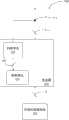
本发明的一实施例为一种变流装置100,其示意图描绘于图1A及图1B。An embodiment of the present invention is a
如图1A所示,可再生能源系统105将自然的能源转换成一电能E(Electricalenergy),并将电能E传送至变流器101。As shown in FIG. 1A , the
于本实施例中,变流装置100包含变流器101。变流器101自可再生能源系统105接收电能E,并将电能E转换为输出电流Iout以产生输出端电压Vout-term。需说明者,输出端电压Vout-term相对于输出电流Iout及外部阻抗(图未绘示)所产生的输出端的电压,并非由变流器直接产生。具体而言,变流器101输出端与市电的连接之间具有外部阻抗,外部阻抗输出电流Iout在流过后会行成电压降,此电压降随着输出电流Iout增加而增加,在市电电压大小不变的情况下,输出端电压Vout-term会随着输出电流Iout的增加而相应的增加。此外,市电、输出电流Iout及输出端电压Vout-term均可为交流电,因此在交流电的情形下,此处的增加指的是最大振幅的增加或者说是方均根值的增加。In this embodiment, the
于本实施例中,当输出电流Iout上升时,输出端的电压相应地上升。举例而言,当外部阻抗(例如:馈线)因为老化及温度上升时,会造成馈线阻抗上升,因此输出电流Iout上升时,馈线阻抗上的电压相应地上升。In this embodiment, when the output current Iout increases, the voltage at the output end increases accordingly. For example, when the external impedance (for example: feeder) is aged and the temperature rises, the impedance of the feeder will increase, so when the output current Iout increases, the voltage on the impedance of the feeder will increase accordingly.
如图1A所示,变流器101具有一控制单元107,当输出端电压Vout-term升高且进入一警戒范围时,控制单元107用以控制变流器101以降低输出电流Iout,或者是维持当下的输出电流Iout以避免输出端电压上升且超过电压门限值(即,超过警戒范围的上限电压)而造成变流器101进入一跳脱保护机制,例如避免变流器101超过电压门限值而跳脱(即,停止输出转换输出电流Iout)。需说明的是,跳脱保护机制还可以是前述的最大功率点追踪装置、防孤岛跳脱保护机制等,且任何使变流器101停止产生输出电流Iout的机制皆在本发明保护的范围。As shown in FIG. 1A , the
于本实施例中,变流器101更包含判断单元103。当判断单元103判断输出端电压Vout-term进入一警戒范围时,判断单元103会产生调整信号102,并传送调整信号102至控制单元107,使控制单元107依据调整信号102调整变流器101的输出电流Iout。In this embodiment, the
于另一实施例中,判断单元103更可以根据输出电流Iout及输出端电压Vout-term计算出一判断值,并根据判断值产生一调整信号102用以调整变流器101的输出电流Iout。In another embodiment, the judging
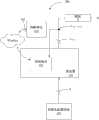
如图1B所示,于另一实施例中,判断单元103可有线或无线连接至控制单元107。具体而言,判断单元103可与控制单元107耦接或透过通讯界面连接,并被设置于远端,控制单元107将接收到的输出电流Iout及输出端电压Vout-term以有线或无线方式传送至判断单元103。以图1B所示为例,判断单元103可透过无线(Wireless)网路与控制单元107无线连接,通过远端控制将调整信号102传送至控制单元107,使控制单元107根据调整信号102调整输出电流Iout。As shown in FIG. 1B , in another embodiment, the judging
本发明的一实施例为一种变流装置200,其示意图描绘于图2A及图2B中。An embodiment of the present invention is a
于本实施例中,举例而言,前述的警戒范围的下限可以是260伏特,且前述的电压门限值可以是264伏特(即,警戒范围为260伏特至264伏特,即警戒范围的下限与电压门限值之间)。当输出电流Iout在多个取样时间持续上升,且输出端电压Vout-term大于警戒范围的下限260伏特时,控制单元107会控制变流器101,通过减少电能E的接收量来减少输出电流Iout,或者是通过维持电能E的接收量以维持当前的输出电流Iout,以避免输出端电压Vout-term超过电压门限值264伏特而进入前述的跳脱保护机制。In this embodiment, for example, the lower limit of the aforementioned warning range can be 260 volts, and the aforementioned voltage threshold value can be 264 volts (that is, the warning range is 260 volts to 264 volts, that is, the lower limit of the warning range and between voltage thresholds). When the output current Iout continues to rise for several sampling times, and the output terminal voltage Vout-term is greater than the lower limit of the warning range of 260 volts, the
另一方面,当输出电流Iout在多个取样时间持续下降,且输出端电压Vout-term大于警戒范围下限260伏特时,控制单元107用以控制变流器101,通过增加电能E的接收量以维持当前的输出电流Iout。On the other hand, when the output current Iout continues to drop for a plurality of sampling times, and the output terminal voltage Vout-term is greater than the lower limit of the warning range of 260 volts, the
具体而言,如第2A及2B图所示,判断单元103会在多个取样时间内判断输出电流Iout为上升或下降,并传送调整信号102至控制单元107,使控制单元107依据调整信号102调整变流器101的输出电流Iout。需说明的是,上述的警戒范围的下限260伏特及电压门限值264伏特皆仅用以解释本发明,但不以此为限。图2A及图2B与图1A及图1B相比绘示了外部阻抗Z。外部阻抗Z对于变流器101的影响与第1A及1B图相似,在此不再赘述。Specifically, as shown in Figures 2A and 2B, the judging
于另一实施例中,当输出端电压Vout-term在多个取样时间持续上升,且输出端电压Vout-term大于警戒范围的下限260伏特时,控制单元107控制变流器101,通过减少电能E的接收量以减少输出电流Iout,或者通过维持电能E的接收量以维持当前的输出电流Iout。In another embodiment, when the output terminal voltage Vout-term continues to rise for a plurality of sampling times, and the output terminal voltage Vout-term is greater than the lower limit of the warning range of 260 volts, the
于另一实施例中,当输出端电压Vout-term在多个取样时间持续下降,且输出端电压Vout-term大于警戒范围的下限时,控制单元107更控制变流器101,通过增加电能E的接收量以增加输出电流Iout。In another embodiment, when the output terminal voltage Vout-term continues to drop for a plurality of sampling times, and the output terminal voltage Vout-term is greater than the lower limit of the warning range, the
换句话说,判断单元103在多个取样时间里,可通过判断输出端电压Vout-term的电压值是否进入警戒范围,以产生调整信号102,并传送调整信号102至控制单元107,使控制单元107依据调整信号102调整变流器101的输出电流Iout。In other words, the judging
于另一实施例中,当输出端电压Vout-term小于警戒范围的下限260伏特时,为使变流器101能产生最大效能,控制单元107控制变流器101,通过增加电能E的接收量以增加输出电流Iout,使变流器101产生最大的输出电流Iout,但不使输出端电压Vout-term超过电压门限值264伏特,避免使变流器101进入跳脱保护机制。In another embodiment, when the output terminal voltage Vout-term is less than the lower limit of the warning range of 260 volts, in order to enable the
于另一实施例中,判断单元103更可通过判断输出电流Iout及输出端电压Vout-term产生调整信号102以调整变流器101的输出电流Iout。In another embodiment, the judging
具体而言,变流器101将电能E转换为输出电流Iout以产生输出端电压Vout-term。判断单元103根据输出电流Iout的每单位电流的变化量造成输出端电压Vout-term的每单位电压的变化量的比值计算出判断值,此判断值为一阻抗Z。即阻抗Z=d(Vout-term)/d(Iout)。接着,判断单元103根据阻抗Z产生调整信号102。Specifically, the
若阻抗Z大于一预设值,阻抗Z会对于输出端电压Vout-term在输出电流Iout上升的过程中,产生实质地影响,此时需要避免在提升输出电流Iout的同时,造成输出端电压Vout-term过高而使得变流器101进入跳脱保护机制。If the impedance Z is greater than a preset value, the impedance Z will have a substantial impact on the output terminal voltage Vout-term during the rise of the output current Iout . At this time, it is necessary to avoid increasing the output current Iout while causing the output The terminal voltage Vout-term is too high and the
于另一实施例中,判断单元103更用以将输出端电压Vout-term与电压门限值264伏特(即,警戒范围的上限)比较以产生一比较结果,并根据判断值及比较结果产生调整信号102。In another embodiment, the judging
具体而言,若阻抗Z大于一预设值,且输出端电压Vout-term已经接近电压门限值264伏特。举例来说,在电压门限值以下20%范围内,或者是在电压门限值以下10%范围内,判断单元103产生调整电流102,使控制单元107减少或维持变流器101的输出电流Iout。Specifically, if the impedance Z is greater than a predetermined value, and the output terminal voltage Vout-term is close to the voltage threshold value of 264V. For example, within the range of 20% below the voltage threshold, or within the range of 10% below the voltage threshold, the judging
此外,电压门限值更可以是电工法规规定的变流器101的跳脱电压264伏特,若输出端电压Vout-term即将超过电压门限值(即,跳脱电压264伏特),则必须停止或减少变流器101的输出电流Iout。因此,通过判断单元103产生调整信号102来控制变流器101,以限制输出电流Iout继续上升。In addition, the voltage threshold value can be the trip voltage of the
于一本实施例中,如图2C所示,其描述变流装置200a及变流装置200b共同运作的示意图。举例而言,可再生能源系统105a及可再生能源系统105b为太阳能再生系统,变流器101a及变流器101b分别将可再生能源系统105a所产生的电能E1及可再生能源系统105b所产生的电能E2转换为输出电流Iout1及输出电流Iout2,且产生总输出电流Iout_total,并更据以产生输出端电压Vout-term。In one embodiment, as shown in FIG. 2C , it depicts a schematic diagram of the joint operation of the
当判断单元103a及判断单元103b判断输出端电压Vout-term进入警戒范围时,判断单元103a及判断单元103b分别产生调整信号102a及调整信号102b,且分别传送调整信号102a及调整信号102b至控制单元107a及控制单元107b,以降低变流器101a产生的输出电流Iout1及变流器101b产生的输出电流Iout2,使总输出电流Iout_total据此降低。此实施例显示了本发明用于电力调度可有效的保持电力系统的电流品质,更避免可再生系统的发电损失。When the
请参考图2D,其描绘变流装置200的输出端电压Vout-term与时间的关系的示意图。变流装置200的判断单元103可依据输出端电压Vout-term与时间的关系,进行不同的判断阶段,例如图2D所示的6个判断阶段。Please refer to FIG. 2D , which depicts a schematic diagram of the relationship between the output terminal voltage Vout-term of the
于第1阶段,输出端电压Vout-term位于240伏特与255伏特之间,判断单元103判断输出端电压Vout-term为正常电压。因此,判断单元103不使控制单元107调整输出电流Iout,但仍持续保持检测输出端电压Vout-term的上升状况。在另一实施方式中,判断单元103可使控制单元107控制变流器101以提高电能E的接收及输出电流Iout的大小(即,控制可再生能源系统105运作在可能的最大功率输出下)。In the first stage, the output voltage Vout-term is between 240V and 255V, and the judging
于第2阶段,随着输出电流Iout升高,输出端电压Vout-term大于255伏特。此时,判断单元103判断第2阶段为警告阶段。接着,判断单元103判断输出端电压Vout-term未超过警戒范围的下限260伏特(即,未进入警戒范围),判断单元103不使控制单元107调整输出电流Iout,但仍持续保持检测输出端电压Vout-term的上升状况。在另一实施方式中,判断单元103可使控制单元107控制变流器101以提高电能E的接收及输出电流Iout的大小(即,控制可再生能源系统105运作在可能的最大功率输出下)。In the second stage, as the output current Iout increases, the output terminal voltage Vout-term is greater than 255V. At this time, the judging
于第3阶段,输出端电压Vout-term大于260伏特。此时,判断单元103判断输出端电压Vout-term进入为警戒范围,且判断出输出端电压Vout-term仍持续上升。接着,判断单元103产生调整信号102,并传送调整信号102至控制单元107。控制单元107根据调整信号102控制变流器101,通过减少或维持电能E的接收量来减少或维持输出电流Iout。In the third stage, the output terminal voltage Vout-term is greater than 260V. At this time, the judging
换句话说,控制单元107控制变流器101以减少或维持接收可再生能源系统105所产生的电能E,因此变流器101相对应的转换出较少的输出电流Iout,进而达到调整输出电流Iout的功效。需说明的是,调降输出电流Iout的动作在此第3阶段中可持续执行直到输出端电压Vout-term不再上升,或者是在警戒范围可容许误差范围内,进而避免变流器101为了使可再生能源系统105运作在可输出的最大功率点而进入跳脱保护机制,反而造成整个系统停止输出电能。In other words, the
于第4阶段,输出端电压Vout-term大于警戒范围的下限260伏特。此时,判断单元103判断输出端电压Vout-term仍在警戒范围里,且判断出输出端电压Vout-term开始下降。此时,判断单元103产生调整信号并传送调整信号102至控制单元107。即,在不会造成变流器101进入跳脱保护机制的前提下,维持最大可能的转换能量输出。In the fourth stage, the output terminal voltage Vout-term is greater than the lower limit of the warning range, 260V. At this time, the judging
接着,控制单元107控制变流器101以减少或维持可再生能源系统105所产生的电能E的接收量,使变流器101的输出端电压Vout-term不会因为超过警戒范围的上限264伏特而导致变流器101进入跳脱保护机制。Next, the
于第5阶段,输出端电压Vout-term大于255伏特但小于260伏特。此时,判断单元103判断输出端电压Vout-term小于警戒范围的下限260伏特且仍持续下降时,判断单元103判断第5阶段为警告阶段。接着,判断单元103传送调整信号102至控制单元107。控制单元107根据调整信号102控制变流器101,此时输出电流Iout的调整目标恢复为尽可能获取最多的再生能源,因此控制单元107控制变流器101通过增加电能E的接收量来增加输出电流Iout。In the fifth stage, the output terminal voltage Vout-term is greater than 255V but less than 260V. At this time, when the judging
于第6阶段,输出端电压Vout-term位于240伏特与255伏特之间。判断单元103判断输出端电压Vout-term为正常电压。因此,判断单元103产生调整信号102至控制单元107,使控制器元107控制变流器101,通过增加电能E的接收量来增加输出电流Iout。需说明者,上述的各个判断阶段仅用以解释本发明,且上述的电压值以及各个判断阶段的顺序亦仅为举例,并非用以限制本发明所保护的范围。In the sixth stage, the output terminal voltage Vout-term is between 240V and 255V. The judging
于另一实施例中,判断单元103更用以将输出电流Iout与电流门限值比较,以及将输出端电压Vout-term与另一电压门限值(例如:警戒范围的下限260伏特)比较以产生一比较结果,并根据判断值及比较结果产生调整信号102。In another embodiment, the judging
如图2D所示,于第1阶段,输出端电压Vout-term位于240伏特与255伏特之间,判断单元103根据输出电流Iout的每单位电流的变化量造成输出端电压Vout-term的每单位电压的变化量的比值计算出阻抗Z。此时,判断单元103计算出的阻抗Z未大于一预设值,判断单元103判断输出端电压Vout-term为正常电压。因此,判断单元103不使控制单元107调整输出电流Iout,但仍持续保持检测阻抗Z、输出电流Iout及输出端电压Vout-term的上升状况。As shown in FIG. 2D, in the first stage, the output terminal voltage Vout-term is between 240 volts and 255 volts, and the judging
于第2阶段,随着输出电流Iout升高,输出端电压Vout-term大于255伏特但未超过警戒范围的下限260伏特。此时,判断单元103判断计算出的阻抗Z大于预设值,并判断第2阶段为警告阶段。接着,判断单元103将输出电流Iout及输出端电压Vout-term分别与电流门限值及警戒范围的下限260伏特比较,并产生比较结果。当比较结果指示为输出电流Iout及输出端电压Vout-term皆处于正常范围,即未进入警戒范围时,判断单元103不使控制单元107调整输出电流Iout,但仍持续保持检测阻抗Z、输出电流Iout及输出端电压Vout-term的上升状况。In the second stage, as the output current Iout increases, the output terminal voltage Vout-term is greater than 255V but does not exceed the lower limit of the warning range of 260V. At this time, the judging
于第3阶段,输出端电压Vout-term大于260伏特。此时,判断单元103判断计算出的阻抗Z大于预设值,并且输出电流Iout及输出端电压Vout-term持续上升,判断单元103判断第3阶段为警戒范围。接着,判断单元103分别将输出电流Iout及输出端电压Vout-term与电流门限值及警戒范围的下限260伏特作比较。当判断单元103判断输出电流Iout大于电流门限值及输出端电压Vout-term大于警戒范围的下限260伏特时,传送调整信号102至控制单元107。In the third stage, the output terminal voltage Vout-term is greater than 260V. At this time, the judging
控制单元107根据调整信号102控制变流器101,通过减少电能E的接收量以达到减少输出电流Iout的目标。换句话说,控制单元107控制变流器101以减少接收可再生能源系统105所产生的电能E,因此变流器101相对应的转换出较少的输出电流Iout,达到调整输出电流Iout的功效。需说明的是,调降输出电流Iout的动作在此第3阶段中会持续执行直到输出端电压Vout-term不再上升,或者是在警戒范围可容许误差范围内。The
于第4阶段,输出端电压Vout-term大于警戒范围的下限260伏特。此时,判断单元103判断计算出的阻抗Z大于预设值时,判断第4阶段为警戒范围。接着,判断单元103将输出电流Iout及输出端电压Vout-term分别与电流门限值及警戒范围的下限260伏特做比较。当比较结果指示为输出端电压Vout-term下降但仍大于警戒范围的下限260伏特时,可维持不变,即不改变输出电流Iout,且亦可传送调整信号102至控制单元107。In the fourth stage, the output terminal voltage Vout-term is greater than the lower limit of the warning range, 260V. At this time, when the judging
控制单元107控制变流器101减少调整可再生能源系统105所产生的电能E的接收量,以调整输出电流Iout,使变流器101的输出端电压Vout-term不会因为超过警戒范围而导致变流器101进入跳脱保护机制。The
于第5阶段,输出端电压Vout-term大于255伏特但小于警戒范围的下限260伏特。此时,判断单元103判断计算出的阻抗Z大于预设值,并且输出电流Iout及输出端电压Vout-term持续下降时,判断单元103判断第5阶段为警告阶段。接着,判断单元103将输出电流Iout与电流门限值比较及将输出端电压Vout-term与警戒范围的下限260伏特做比较。当判断单元103判断输出电流Iout小于电流门限值及输出端电压Vout-term小于警戒范围的下限260伏特时,传送调整信号102至控制单元107。控制单元107根据调整信号102控制变流器101,此时输出电流Iout的调整目标恢复为尽可能获取最多的再生能源。In the fifth stage, the output terminal voltage Vout-term is greater than 255V but less than the lower limit of the warning range of 260V. At this time, when the judging
于第6阶段,输出端电压Vout-term位于240伏特与255伏特之间。判断单元103判断计算出的阻抗Z未大于预设值时,判断单元103判断输出端电压Vout-term为正常电压。因此,判断单元103不使控制单元107调整输出电流Iout,但仍持续保持检测阻抗Z、输出电流Iout及输出端电压Vout-term的上升状况。In the sixth stage, the output terminal voltage Vout-term is between 240V and 255V. When the judging
于另一实施例中,变流器101将电能E转换为输出电流Iout以产生输出端电压Vout-term。判断单元103根据输出端电压Vout-term与至少一警戒范围的下限比较,计算出至少一个判断值,并产生调整信号102,使控制单元107依序调整输出电流Iout。In another embodiment, the
举例而言,当输出端电压Vout-term超过此至少一警戒范围的下限时,判断单元103产生降低输出电流Iout一级的调整信号102,随着输出端电压Vout-term继续增加,控制单元107持续接收降低输出电流Iout的调整信号102,直到输出端电压Vout-term不再增加或是不超过此至少一警戒范围的下限。For example, when the output terminal voltage Vout-term exceeds the lower limit of the at least one warning range, the judging
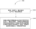
本发明的一实施例为一种变流装置的控制方法300,其流程图描绘于图3中。应了解到,本实施方式中所提及的控制方法的步骤,除特别叙明其顺序者外,均可依实际需要调整其前后顺序,甚至可同时或部分同时执行,且此实施方式可透过上述的各个变流装置的实施例来实现。An embodiment of the present invention is a
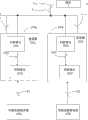
于步骤S301中,转换一电能为一输出电流以产生一输出端电压。接着,于步骤S303中,当输出端电压随着输出电流的升高而升高且进入一警戒范围时,控制变流器降低输出电流或者维持当下的输出电流以避免输出端电压继续升高而超过一电压门限值而造成变流器进入一跳脱保护机制。In step S301, an electric energy is converted into an output current to generate an output terminal voltage. Next, in step S303, when the voltage at the output terminal rises with the increase of the output current and enters a warning range, control the converter to reduce the output current or maintain the current output current to prevent the voltage at the output terminal from continuing to rise. Exceeding a voltage threshold causes the converter to enter a tripping protection mechanism.
本发明的一实施例为一种变流装置的控制方法400,其流程图描绘于图4中。An embodiment of the present invention is a
首先,执行步骤S401,转换一电能为一输出电流以产生一输出端电压。接着,执行步骤S403,对输出电流在多个时间点进行取样。于步骤S405中,当输出电流在多个取样时间持续上升,且输出端电压大于警戒范围的下限时,通过减少电能的接收量以减少输出电流或者通过维持电能的接收量以维持当前的输出电流。于步骤S407中,当输出端电压小于警戒范围的下限时,通过增加电能的接收量以增加输出电流。Firstly, step S401 is executed to convert an electric energy into an output current to generate an output terminal voltage. Next, step S403 is executed to sample the output current at multiple time points. In step S405, when the output current continues to rise for a plurality of sampling times and the voltage at the output terminal is greater than the lower limit of the warning range, the output current is reduced by reducing the received amount of electric energy or the current output current is maintained by maintaining the received amount of electric energy . In step S407, when the voltage at the output terminal is lower than the lower limit of the warning range, the output current is increased by increasing the amount of electric energy received.
本发明的一实施例为一种变流装置的控制方法500,其流程图描绘于图5中。An embodiment of the present invention is a control method 500 of a flow conversion device, the flow chart of which is depicted in FIG. 5 .
首先,执行步骤S501,转换一电能为一输出电流以产生一输出端电压。接着,执行步骤S503,对输出电流在多个时间点进行取样。于步骤S505中,当输出电流在多个取样时间持续下降,且输出端电压大于警戒范围的下限时,通过增加电能的接收量以维持当前的输出电流。于步骤S507中,当输出端电压小于警戒范围的下限时,通过增加电能的接收量以增加输出电流。Firstly, step S501 is executed to convert an electric energy into an output current to generate an output terminal voltage. Next, step S503 is executed to sample the output current at multiple time points. In step S505 , when the output current continues to drop for a plurality of sampling times and the voltage at the output terminal is greater than the lower limit of the warning range, the current output current is maintained by increasing the amount of electric energy received. In step S507, when the voltage at the output terminal is lower than the lower limit of the warning range, the output current is increased by increasing the amount of electric energy received.
本发明的一实施例为一种变流装置的控制方法600,其流程图描绘于图6中。An embodiment of the present invention is a
首先,执行步骤S601,转换一电能为一输出电流以产生一输出端电压。接着,执行步骤S603,对输出电流在多个时间点进行取样。于步骤S605中,当输出端电压在多个取样时间持续上升,且输出端电压大于警戒范围的下限时,通过减少电能的接收量以减少输出电流或者通过维持电能的接收量以维持当前的输出电流。于步骤S607中,当输出端电压小于警戒范围的下限时,通过增加电能的接收量以增加输出电流。Firstly, step S601 is executed to convert an electric energy into an output current to generate an output terminal voltage. Next, step S603 is executed to sample the output current at multiple time points. In step S605, when the voltage at the output terminal continues to rise for a plurality of sampling times, and the voltage at the output terminal is greater than the lower limit of the warning range, the output current is reduced by reducing the received amount of electric energy or the current output is maintained by maintaining the received amount of electric energy current. In step S607, when the voltage at the output terminal is lower than the lower limit of the warning range, the output current is increased by increasing the received amount of electric energy.
本发明的一实施例为一种变流装置的控制方法700,其流程图描绘于图7中。An embodiment of the present invention is a control method 700 of a flow conversion device, the flow chart of which is depicted in FIG. 7 .
首先,执行步骤S701,转换一电能为一输出电流以产生一输出端电压。接着,执行步骤S703,对输出电流在多个时间点进行取样。于步骤S705中,当输出端电压在多个取样时间持续下降,且输出端电压大于警戒范围的下限时,通过增加电能的接收量以维持当前的输出电流。于步骤S707中,当输出端电压小于警戒范围的下限时,通过增加电能的接收量以增加输出电流。Firstly, step S701 is executed to convert an electric energy into an output current to generate an output terminal voltage. Next, step S703 is executed to sample the output current at multiple time points. In step S705 , when the voltage at the output terminal continues to drop for a plurality of sampling times, and the voltage at the output terminal is greater than the lower limit of the warning range, the current output current is maintained by increasing the received amount of electric energy. In step S707, when the voltage at the output terminal is lower than the lower limit of the warning range, the output current is increased by increasing the amount of electric energy received.
除此之外,上述实施例的控制方法300、400、500、600、700亦能执行上述实施例的变流装置100、200所描述的所有操作及功能,本领域技术人员可直接了解其运作,故在此不再赘述。In addition, the
由上述各实施例的说明可知,通过本发明的变流装置及其控制方法,可避免变流器因线阻的电压差效应而交替地操作于正常供电以及跳脱保护机制这两个模式之间,通过控制器控制变流器的输出电流,以避免输出端电压上升且超过警戒范围,更避免变流器进入跳脱保护机制。当输出端电压上升且进入警戒范围时,控制器会维持、增加或减少接收自可再生能源输出的电流量,相对应地可维持、增加或减少变流器的输出电流。据此,可有效的保持变流器产生的电流品质,更避免可再生能源系统的发电损失。From the descriptions of the above embodiments, it can be seen that the converter device and its control method of the present invention can prevent the converter from alternately operating in the two modes of normal power supply and tripping protection mechanism due to the voltage difference effect of the line resistance During the period, the output current of the converter is controlled by the controller to prevent the voltage at the output terminal from rising and exceeding the warning range, and to prevent the converter from entering the tripping protection mechanism. When the output terminal voltage rises and enters the warning range, the controller maintains, increases or decreases the current received from the renewable energy output, and correspondingly maintains, increases or decreases the output current of the converter. Accordingly, the quality of the current generated by the converter can be effectively maintained, and the power generation loss of the renewable energy system can be avoided.
虽然本案已以实施例揭露如上,然其并非用以限定本案,任何本领域技术人员,在不脱离本案的精神和范围内,当可作各种的更动与润饰,因此本案的保护范围当以权利要求书为准。Although this case has been disclosed above with the embodiment, it is not used to limit this case. Any person skilled in the art can make various changes and modifications without departing from the spirit and scope of this case. Therefore, the protection scope of this case should be The claims shall prevail.
Claims (12)
Translated fromChinesePriority Applications (4)
| Application Number | Priority Date | Filing Date | Title |
|---|---|---|---|
| CN201310473976.6ACN103580463A (en) | 2013-10-11 | 2013-10-11 | Converter device and control method thereof |
| PCT/CN2013/086861WO2015051570A1 (en) | 2013-10-11 | 2013-11-11 | Converter apparatus and control method therefor |
| TW102144598ATWI505622B (en) | 2013-10-11 | 2013-12-05 | Inverting apparatus and control method thereof |
| US14/284,789US20150103572A1 (en) | 2013-10-11 | 2014-05-22 | Inverting apparatus and control method thereof |
Applications Claiming Priority (1)
| Application Number | Priority Date | Filing Date | Title |
|---|---|---|---|
| CN201310473976.6ACN103580463A (en) | 2013-10-11 | 2013-10-11 | Converter device and control method thereof |
Publications (1)
| Publication Number | Publication Date |
|---|---|
| CN103580463Atrue CN103580463A (en) | 2014-02-12 |
Family
ID=50051590
Family Applications (1)
| Application Number | Title | Priority Date | Filing Date |
|---|---|---|---|
| CN201310473976.6APendingCN103580463A (en) | 2013-10-11 | 2013-10-11 | Converter device and control method thereof |
Country Status (4)
| Country | Link |
|---|---|
| US (1) | US20150103572A1 (en) |
| CN (1) | CN103580463A (en) |
| TW (1) | TWI505622B (en) |
| WO (1) | WO2015051570A1 (en) |
Cited By (12)
| Publication number | Priority date | Publication date | Assignee | Title |
|---|---|---|---|---|
| CN112636399A (en)* | 2019-09-24 | 2021-04-09 | 北京小米移动软件有限公司 | Charging method and device, terminal equipment and storage medium |
| CN113131859A (en)* | 2016-05-25 | 2021-07-16 | 太阳能安吉科技有限公司 | Photovoltaic power device and wiring |
| US12191668B2 (en) | 2012-01-30 | 2025-01-07 | Solaredge Technologies Ltd. | Maximizing power in a photovoltaic distributed power system |
| US12218505B2 (en) | 2011-01-12 | 2025-02-04 | Solaredge Technologies Ltd. | Serially connected inverters |
| US12224706B2 (en) | 2006-12-06 | 2025-02-11 | Solaredge Technologies Ltd. | Pairing of components in a direct current distributed power generation system |
| US12276997B2 (en) | 2006-12-06 | 2025-04-15 | Solaredge Technologies Ltd. | Distributed power harvesting systems using DC power sources |
| US12281919B2 (en) | 2006-12-06 | 2025-04-22 | Solaredge Technologies Ltd. | Monitoring of distributed power harvesting systems using DC power sources |
| US12306215B2 (en) | 2009-05-26 | 2025-05-20 | Solaredge Technologies Ltd. | Theft detection and prevention in a power generation system |
| US12348182B2 (en) | 2016-04-05 | 2025-07-01 | Solaredge Technologies Ltd. | Safety switch for photovoltaic systems |
| US12388492B2 (en) | 2006-12-06 | 2025-08-12 | Solaredge Technologies Ltd. | Safety mechanisms, wake up and shutdown methods in distributed power installations |
| US12407158B2 (en) | 2010-11-09 | 2025-09-02 | Solaredge Technologies Ltd. | Arc detection and prevention in a power generation system |
| US12418177B2 (en) | 2009-10-24 | 2025-09-16 | Solaredge Technologies Ltd. | Distributed power system using direct current power sources |
Families Citing this family (2)
| Publication number | Priority date | Publication date | Assignee | Title |
|---|---|---|---|---|
| US12095385B2 (en)* | 2020-03-12 | 2024-09-17 | Tmeic Corporation | Power conversion device that calculates an estimated value of an upper impedance |
| CN111525517B (en)* | 2020-04-14 | 2022-07-22 | 西安许继电力电子技术有限公司 | A method and system for suppressing overvoltage of a converter valve sub-module |
Citations (5)
| Publication number | Priority date | Publication date | Assignee | Title |
|---|---|---|---|---|
| CN1450716A (en)* | 2002-03-14 | 2003-10-22 | 三垦电气株式会社 | Converter and control method |
| GB2419968A (en)* | 2004-11-08 | 2006-05-10 | Enecsys Ltd | Regulating the voltage fed to a power converter |
| TW200703858A (en)* | 2005-05-18 | 2007-01-16 | Samsung Electro Mech | DC-DC converter having protective function of over-voltage and over-current and LED driving circuit using the same |
| TWM356978U (en)* | 2009-01-09 | 2009-05-11 | Der Ee Electrical Instr Co Ltd | Warning alarm for current detection |
| CN103346584A (en)* | 2013-06-27 | 2013-10-09 | 深圳市汇川技术股份有限公司 | Photovoltaic grid-connected system and power compensation method |
Family Cites Families (7)
| Publication number | Priority date | Publication date | Assignee | Title |
|---|---|---|---|---|
| US4347541A (en)* | 1981-01-14 | 1982-08-31 | Gte Laboratories Incorporated | Circuit breaker |
| US6281485B1 (en)* | 2000-09-27 | 2001-08-28 | The Aerospace Corporation | Maximum power tracking solar power system |
| US7193872B2 (en)* | 2005-01-28 | 2007-03-20 | Kasemsan Siri | Solar array inverter with maximum power tracking |
| JP4566267B1 (en)* | 2009-04-21 | 2010-10-20 | シャープ株式会社 | Power supply |
| JP5864222B2 (en)* | 2011-11-15 | 2016-02-17 | 住友電気工業株式会社 | Transistor protection circuit |
| KR101621994B1 (en)* | 2011-12-30 | 2016-05-17 | 엘에스산전 주식회사 | Control apparatus for regenerative medium voltage inverter |
| CN102545646B (en)* | 2012-01-18 | 2014-06-04 | 华北电力大学 | Abnormal voltage ride-through power supply of frequency converter |
- 2013
- 2013-10-11CNCN201310473976.6Apatent/CN103580463A/enactivePending
- 2013-11-11WOPCT/CN2013/086861patent/WO2015051570A1/enactiveApplication Filing
- 2013-12-05TWTW102144598Apatent/TWI505622B/ennot_activeIP Right Cessation
- 2014
- 2014-05-22USUS14/284,789patent/US20150103572A1/ennot_activeAbandoned
Patent Citations (5)
| Publication number | Priority date | Publication date | Assignee | Title |
|---|---|---|---|---|
| CN1450716A (en)* | 2002-03-14 | 2003-10-22 | 三垦电气株式会社 | Converter and control method |
| GB2419968A (en)* | 2004-11-08 | 2006-05-10 | Enecsys Ltd | Regulating the voltage fed to a power converter |
| TW200703858A (en)* | 2005-05-18 | 2007-01-16 | Samsung Electro Mech | DC-DC converter having protective function of over-voltage and over-current and LED driving circuit using the same |
| TWM356978U (en)* | 2009-01-09 | 2009-05-11 | Der Ee Electrical Instr Co Ltd | Warning alarm for current detection |
| CN103346584A (en)* | 2013-06-27 | 2013-10-09 | 深圳市汇川技术股份有限公司 | Photovoltaic grid-connected system and power compensation method |
Cited By (13)
| Publication number | Priority date | Publication date | Assignee | Title |
|---|---|---|---|---|
| US12388492B2 (en) | 2006-12-06 | 2025-08-12 | Solaredge Technologies Ltd. | Safety mechanisms, wake up and shutdown methods in distributed power installations |
| US12224706B2 (en) | 2006-12-06 | 2025-02-11 | Solaredge Technologies Ltd. | Pairing of components in a direct current distributed power generation system |
| US12276997B2 (en) | 2006-12-06 | 2025-04-15 | Solaredge Technologies Ltd. | Distributed power harvesting systems using DC power sources |
| US12281919B2 (en) | 2006-12-06 | 2025-04-22 | Solaredge Technologies Ltd. | Monitoring of distributed power harvesting systems using DC power sources |
| US12306215B2 (en) | 2009-05-26 | 2025-05-20 | Solaredge Technologies Ltd. | Theft detection and prevention in a power generation system |
| US12418177B2 (en) | 2009-10-24 | 2025-09-16 | Solaredge Technologies Ltd. | Distributed power system using direct current power sources |
| US12407158B2 (en) | 2010-11-09 | 2025-09-02 | Solaredge Technologies Ltd. | Arc detection and prevention in a power generation system |
| US12218505B2 (en) | 2011-01-12 | 2025-02-04 | Solaredge Technologies Ltd. | Serially connected inverters |
| US12191668B2 (en) | 2012-01-30 | 2025-01-07 | Solaredge Technologies Ltd. | Maximizing power in a photovoltaic distributed power system |
| US12348182B2 (en) | 2016-04-05 | 2025-07-01 | Solaredge Technologies Ltd. | Safety switch for photovoltaic systems |
| CN113131859A (en)* | 2016-05-25 | 2021-07-16 | 太阳能安吉科技有限公司 | Photovoltaic power device and wiring |
| CN112636399A (en)* | 2019-09-24 | 2021-04-09 | 北京小米移动软件有限公司 | Charging method and device, terminal equipment and storage medium |
| CN112636399B (en)* | 2019-09-24 | 2023-08-04 | 北京小米移动软件有限公司 | Charging method and device, terminal equipment and storage medium |
Also Published As
| Publication number | Publication date |
|---|---|
| WO2015051570A1 (en) | 2015-04-16 |
| TWI505622B (en) | 2015-10-21 |
| TW201515377A (en) | 2015-04-16 |
| US20150103572A1 (en) | 2015-04-16 |
Similar Documents
| Publication | Publication Date | Title |
|---|---|---|
| CN103580463A (en) | Converter device and control method thereof | |
| JP6342535B2 (en) | Automatic voltage regulation for photovoltaic systems | |
| CN101682192B (en) | Method and system for influencing power generation by a variable speed generator | |
| CN102163851B (en) | Control method for power source converter | |
| TWI466406B (en) | Solar power generation system and power supply system | |
| CN108092296A (en) | DC transmission system and method | |
| KR20130050935A (en) | Method for leakage current control in a inverter system | |
| CN106786737B (en) | A kind of low voltage traversing control method for collecting and distributing type photovoltaic generating system | |
| CN101226411B (en) | Power consumption measuring and control method for sound system switch power source as well as special device thereof | |
| CN107431360A (en) | Electric power transmission network | |
| CN108695883B (en) | Control system in converter and method of operating converter | |
| JP2015211480A (en) | Voltage rise suppression and control method of power generation system | |
| JP2015220979A (en) | Converter and operating method thereof | |
| CN106463971A (en) | Centralized DC curtailment for overvoltage protection | |
| CN111492551A (en) | Adaptive active power control for renewable energy power plants | |
| CN202444279U (en) | Countercurrent prevention system | |
| CN106655257B (en) | Energy management system and method for port shore power based on new energy hybrid power supply | |
| KR101630511B1 (en) | Converter controller and operating method thereof | |
| CN107431359A (en) | Electric power transmission network | |
| CN215300160U (en) | A photovoltaic grid-connected system with coordinated control to prevent DC overvoltage | |
| US12136819B2 (en) | Power conversion system | |
| CN202495889U (en) | Intelligent photovoltaic power generation system | |
| CN103988138B (en) | Automatic voltage regulation for photovoltaic systems | |
| CN105356737B (en) | High voltage converter output voltage is from equalization methods | |
| CN119109137A (en) | A monitoring-based automatic power control method for micro-inverters |
Legal Events
| Date | Code | Title | Description |
|---|---|---|---|
| C06 | Publication | ||
| PB01 | Publication | ||
| SE01 | Entry into force of request for substantive examination | ||
| SE01 | Entry into force of request for substantive examination | ||
| WD01 | Invention patent application deemed withdrawn after publication | ||
| WD01 | Invention patent application deemed withdrawn after publication | Application publication date:20140212 |