CN103576266A - Fiber optic connector - Google Patents
Fiber optic connectorDownload PDFInfo
- Publication number
- CN103576266A CN103576266ACN201210280488.9ACN201210280488ACN103576266ACN 103576266 ACN103576266 ACN 103576266ACN 201210280488 ACN201210280488 ACN 201210280488ACN 103576266 ACN103576266 ACN 103576266A
- Authority
- CN
- China
- Prior art keywords
- intermediate shaft
- optical fiber
- fibre junction
- spool
- shaft
- Prior art date
- Legal status (The legal status is an assumption and is not a legal conclusion. Google has not performed a legal analysis and makes no representation as to the accuracy of the status listed.)
- Granted
Links
Images


Classifications
- G—PHYSICS
- G02—OPTICS
- G02B—OPTICAL ELEMENTS, SYSTEMS OR APPARATUS
- G02B6/00—Light guides; Structural details of arrangements comprising light guides and other optical elements, e.g. couplings
- G02B6/44—Mechanical structures for providing tensile strength and external protection for fibres, e.g. optical transmission cables
- G02B6/4439—Auxiliary devices
- G02B6/444—Systems or boxes with surplus lengths
- G02B6/4441—Boxes
- G—PHYSICS
- G02—OPTICS
- G02B—OPTICAL ELEMENTS, SYSTEMS OR APPARATUS
- G02B6/00—Light guides; Structural details of arrangements comprising light guides and other optical elements, e.g. couplings
- G02B6/24—Coupling light guides
- G02B6/36—Mechanical coupling means
- G02B6/38—Mechanical coupling means having fibre to fibre mating means
- G02B6/3801—Permanent connections, i.e. wherein fibres are kept aligned by mechanical means
- G02B6/3803—Adjustment or alignment devices for alignment prior to splicing
- G—PHYSICS
- G02—OPTICS
- G02B—OPTICAL ELEMENTS, SYSTEMS OR APPARATUS
- G02B6/00—Light guides; Structural details of arrangements comprising light guides and other optical elements, e.g. couplings
- G02B6/44—Mechanical structures for providing tensile strength and external protection for fibres, e.g. optical transmission cables
- G02B6/4439—Auxiliary devices
- G02B6/4457—Bobbins; Reels
- G—PHYSICS
- G02—OPTICS
- G02B—OPTICAL ELEMENTS, SYSTEMS OR APPARATUS
- G02B6/00—Light guides; Structural details of arrangements comprising light guides and other optical elements, e.g. couplings
- G02B6/46—Processes or apparatus adapted for installing or repairing optical fibres or optical cables
- G02B6/47—Installation in buildings
- G02B6/475—Mechanical aspects of installing cables in ducts or the like for buildings
Landscapes
- Physics & Mathematics (AREA)
- General Physics & Mathematics (AREA)
- Optics & Photonics (AREA)
- Engineering & Computer Science (AREA)
- Civil Engineering (AREA)
- Structural Engineering (AREA)
- Light Guides In General And Applications Therefor (AREA)
- Storage Of Web-Like Or Filamentary Materials (AREA)
Abstract
Description
Translated fromChinese技术领域technical field
本发明涉及一种光纤接续组件,特别是,涉及一种可安装在安装壁上的具有卷轴的光纤接续组件。The invention relates to an optical fiber connection assembly, in particular to an optical fiber connection assembly with a reel which can be installed on an installation wall.
背景技术Background technique
在光缆通信网络中,来自外部的光缆中的多条光纤分别与各个用户的独立光纤通过光纤接续的方式连接,从而形成通信网络。光纤接续盒作为一种对不同光纤进行接续的设备,广泛应用于光缆通信网络中,适用于各种结构光缆的架空、管道、直埋等安装环境。In the optical cable communication network, multiple optical fibers in the optical cable from the outside are respectively connected to the independent optical fibers of each user through optical fiber splicing, thereby forming a communication network. As a device for splicing different optical fibers, the optical fiber splicing box is widely used in optical cable communication networks, and is suitable for installation environments such as overhead, pipeline, and direct burial of optical cables with various structures.
传统的光纤接续盒的托盘上一般包括由于存储冗余光纤的光纤存储装置和多个中间轴,所述中间轴用于安装对不同的光纤实现接续的光纤接续装置,例如机械接续装置、熔接接续装置等。虽然传统的光纤接线盒设有用于体积较小的存储冗余光纤的存储装置,但却不能超出体积较大的冗余光缆。因此需要根据用于安装接线盒的支撑面板、以及接线盒的布置方式预留具有一定长度的冗余光缆。如果冗余光缆的长度预留的太短,则可能影响对光缆的光纤的顺利对接。另一方面,如果冗余光缆的长度预留的太长,则不利于光缆及其光纤的维护和管理。The tray of a traditional optical fiber splicing box generally includes an optical fiber storage device for storing redundant optical fibers and a plurality of intermediate shafts, and the intermediate shafts are used to install optical fiber splicing devices for splicing different optical fibers, such as mechanical splicing devices, fusion splicing, etc. device etc. Although traditional fiber optic junction boxes have storage devices for storing redundant optical fibers in smaller volumes, they cannot exceed larger redundant optical fiber cables. Therefore, it is necessary to reserve redundant optical cables with a certain length according to the support panel used for installing the junction box and the layout of the junction box. If the reserved length of the redundant optical cable is too short, it may affect the smooth connection of the optical fibers of the optical cable. On the other hand, if the length of the redundant optical cable is reserved too long, it is not conducive to the maintenance and management of the optical cable and its optical fibers.
在另外一些传统的光纤接续盒中,虽然设有用于预存光缆的卷轴,但不能将此卷轴嵌入墙内安装。因此占用空间,影响美观。In some other traditional optical fiber splice closures, although there is a reel for pre-storing optical cables, the reel cannot be embedded in the wall for installation. Therefore, it takes up space and affects the appearance.
发明内容Contents of the invention
为解决现有技术中的上述和其它技术问题,本发明提出一种可快速安装到安装壁上的光纤接续组件,其用于存储光缆或者光纤的卷轴可部分地采用嵌入方式安装在安装壁中。In order to solve the above-mentioned and other technical problems in the prior art, the present invention proposes an optical fiber splicing assembly that can be quickly installed on the installation wall, and the reel used to store optical cables or optical fibers can be partially embedded in the installation wall .
本发明进一步提出一种光纤接续组件,光纤存储装置的卷轴具有可收缩到安装壁内的收缩状态和伸出到安装壁外部的伸展状态,便于对冗余的光缆或光纤进行管理和操作。The present invention further proposes an optical fiber splicing assembly. The reel of the optical fiber storage device has a contracted state that can be retracted into the installation wall and an extended state that protrudes outside the installation wall, so as to facilitate management and operation of redundant optical cables or optical fibers.
根据本发明进一步的方面,提供一种可安装到安装壁上的光纤接续组件,所述安装壁上设有安装孔,包括:接续面板,其正面被构造成安装用于实现光纤接续的光纤接续装置;光纤存储装置,至少部分容纳于所述安装孔中,并且光纤存储装置的一端与所述接续面板可拆卸地安装在一起。According to a further aspect of the present invention, there is provided an optical fiber splicing assembly that can be installed on an installation wall, and the installation wall is provided with installation holes, including: a splicing panel, the front of which is configured to install an optical fiber splicing assembly for realizing optical fiber splicing A device; an optical fiber storage device at least partially accommodated in the installation hole, and one end of the optical fiber storage device is detachably installed together with the splicing panel.
在上述光纤接续组件中,所述光纤存储装置包括一卷轴,用于预先存储光缆或光纤。In the above optical fiber splicing assembly, the optical fiber storage device includes a reel for pre-storing optical cables or optical fibers.
在上述光纤接续组件中,所述光纤存储装置还包括一支撑架,所述卷轴安装于所述支撑架上,而所述支撑架用于将所述光纤存储装置固定于所述安装壁上。In the above optical fiber splicing assembly, the optical fiber storage device further includes a support frame, the reel is installed on the support frame, and the support frame is used to fix the optical fiber storage device on the installation wall.
在上述光纤接续组件中,支撑架包括支撑轴,卷轴与支撑轴可相对移动地套接在一起,并且,卷轴可以相对于支撑轴沿轴向从位于安装孔中的收缩状态移动至露于安装孔之外的伸展状态,当卷轴处于伸展状态时,安装人员可以从安装壁外部将存储在所述卷轴上的光缆或者光纤拉出。In the above optical fiber splicing assembly, the support frame includes a support shaft, and the reel and the support shaft are relatively movably nested together, and the reel can move axially relative to the support shaft from a contracted state in the installation hole to being exposed to the installation In the extended state outside the hole, when the reel is in the extended state, the installer can pull the optical cable or optical fiber stored on the reel from the outside of the installation wall.
在上述光纤接续组件中,卷轴与支撑轴可转动地套接在一起。In the above optical fiber splicing assembly, the reel and the support shaft are rotatably sleeved together.
在上述光纤接续组件中,所述光纤存储装置进一步包括中间轴,所述中间轴的第一端与所述卷轴可相对轴向移动地连接,所述中间轴的第二端与所述支撑轴可相对轴向移动地连接。In the above optical fiber splicing assembly, the optical fiber storage device further includes an intermediate shaft, the first end of the intermediate shaft is connected to the reel in a relatively axially movable manner, and the second end of the intermediate shaft is connected to the support shaft Connected to be movable relative to the axial direction.
在上述光纤接续组件中,卷轴与中间轴的第一端可转动地结合。In the above optical fiber splicing assembly, the reel is rotatably combined with the first end of the intermediate shaft.
在上述光纤接续组件中,所述中间轴通过型面配合的方式可滑动地结合到所述支撑轴,以阻止所述中间轴相对于所述支撑轴转动。In the above optical fiber splicing assembly, the intermediate shaft is slidably coupled to the support shaft by means of positive fit, so as to prevent the intermediate shaft from rotating relative to the support shaft.
在上述光纤接续组件中,所述中间轴为大致的套筒结构并可滑动地套接在所述支撑轴上。In the above optical fiber splicing assembly, the intermediate shaft has a substantially sleeve structure and is slidably sleeved on the support shaft.
在上述光纤接续组件中,所述中间轴的内表面和所述支撑轴的外表面中的一个上设有沿轴向方向延伸的多个滑动凹槽,在另一个上设有分别与所述凹槽滑动地配合的多个滑动凸起。In the above optical fiber connection assembly, one of the inner surface of the intermediate shaft and the outer surface of the support shaft is provided with a plurality of sliding grooves extending in the axial direction, and the other is provided with the The groove slidably engages a plurality of sliding protrusions.
在上述光纤接续组件中,所述支撑轴的外表面上设有所述滑动凹槽,所述中间轴的内表面的第一端附近设有所述滑动凸起。In the above optical fiber splicing assembly, the sliding groove is provided on the outer surface of the support shaft, and the sliding protrusion is provided near the first end of the inner surface of the intermediate shaft.
在上述光纤接续组件中,所述滑动凹槽在靠近所述支撑轴的自由端的位置设有第一阻挡凸起和第一限制凸起,在卷轴从收缩状态转换到伸展状态时,所述第一阻挡凸起与所述滑动凸起以锁定方式配合以阻止所述中间轴脱离所述自由端,所述第一限制凸起与所述滑动凸起以卡扣方式配合以限制所述中间轴沿与原来的滑动方向相反的方向滑动。In the above optical fiber splicing assembly, the sliding groove is provided with a first blocking protrusion and a first restricting protrusion near the free end of the support shaft. A blocking protrusion cooperates with the sliding protrusion in a locking manner to prevent the intermediate shaft from breaking away from the free end, and the first restricting protrusion cooperates with the sliding protrusion in a snap-fit manner to restrict the intermediate shaft Swipe in the opposite direction to the original swipe direction.
在上述光纤接续组件中,所述滑动凹槽包括至少一个第一滑动凹槽和至少一个第二滑动凹槽,所述滑动凸起包括至少一个第一滑动凸起和至少一个第二滑动凸起。所述第一滑动凹槽在靠近所述支撑轴的自由端的位置设有第一阻挡凸起,所述第二滑动凹槽在靠近所述自由端的位置设有第一限制凸起,在卷轴从收缩状态转换到伸展状态时,所述第一阻挡凸起与所述第一滑动凸起以锁定方式配合以阻止所述中间轴脱离所述自由端,所述第一限制凸起与所述第二滑动凸起以卡扣方式配合以限制所述中间轴沿与原来的滑动方向相反的方向滑动。In the above optical fiber splicing assembly, the sliding groove includes at least one first sliding groove and at least one second sliding groove, and the sliding protrusion includes at least one first sliding protrusion and at least one second sliding protrusion . The first sliding groove is provided with a first blocking protrusion at a position close to the free end of the support shaft, and the second sliding groove is provided with a first limiting protrusion at a position close to the free end. When the retracted state is converted to the extended state, the first blocking protrusion cooperates with the first sliding protrusion in a locking manner to prevent the intermediate shaft from detaching from the free end, and the first restricting protrusion is connected to the first sliding protrusion. The two sliding protrusions are snap fit to restrict the intermediate shaft from sliding in a direction opposite to the original sliding direction.
在上述光纤接续组件中,所述中间轴的第一端在轴向方向上可移动地结合到所述卷轴的筒体内。In the above optical fiber splicing assembly, the first end of the intermediate shaft is movably coupled in the barrel of the reel in the axial direction.
在上述光纤接续组件中,所述筒体的第一端的内侧设有环形凸起,所述环形凸起与所述中间轴第一端附近的外表面可转动地配合。In the above optical fiber splicing assembly, an annular protrusion is provided on the inner side of the first end of the barrel, and the annular protrusion is rotatably engaged with the outer surface near the first end of the intermediate shaft.
在上述光纤接续组件中,在所述中间轴的第一端设有多个第二阻挡凸起,所述第二阻挡凸起与所述环形凸起的远离所述筒体的第一端的侧缘以锁定方式配合以在所述卷轴从收缩状态转换到伸展状态时阻止所述卷轴脱离所述中间轴的第一端。In the above optical fiber splicing assembly, a plurality of second blocking protrusions are provided at the first end of the intermediate shaft, and the second blocking protrusions are connected with the first end of the annular protrusion away from the cylinder body. The side edges cooperate in a locking manner to prevent disengagement of the spool from the first end of the intermediate shaft when the spool transitions from the retracted state to the extended state.
在上述光纤接续组件中,在所述环形凸起上设有多个第二限制凸起,在所述中间轴的外表面上设有环形凹槽,所述第二限制凸起与所述环形凹槽以卡扣方式配合以在卷轴从收缩状态转换到伸展状态时限制所述卷轴沿与原来的滑动方向相反的方向滑动。In the above optical fiber connection assembly, a plurality of second restricting protrusions are provided on the annular protrusion, and an annular groove is provided on the outer surface of the intermediate shaft, and the second restricting protrusions and the annular The grooves snap fit to restrict sliding of the spool in a direction opposite to the original sliding direction when the spool transitions from the retracted state to the extended state.
在上述光纤接续组件中,所述筒体的第二端的内侧设有环形裙部,所述环形裙部与所述筒体的内壁之间具有间隙,在卷轴处于收缩状态时,所述环形裙部位于所述中间轴的第二端与所述支撑轴的自由端之间,使得所述卷轴能够相对于所述支撑轴和中间轴转动。In the above optical fiber connection assembly, the inner side of the second end of the barrel is provided with an annular skirt, and there is a gap between the annular skirt and the inner wall of the barrel, and when the reel is in a retracted state, the annular skirt A portion is located between the second end of the intermediate shaft and the free end of the support shaft so that the reel can rotate relative to the support shaft and the intermediate shaft.
在上述光纤接续组件中,所述环形裙部上设有环形限制凸起,所述支撑轴的自由端设有第三限制凸起,所述环形限制凸起与所述第三限制凸起以卡扣方式配合以在卷轴处于收缩状态时限制所述卷轴远离所述中间轴移动。In the above optical fiber connection assembly, the annular skirt is provided with an annular restricting protrusion, and the free end of the support shaft is provided with a third restricting protrusion, and the annular restricting protrusion and the third restricting protrusion are separated by A snap fit restricts movement of the spool away from the intermediate shaft when the spool is in the retracted state.
在上述光纤接续组件中,所述支撑架包括:基座,所述支撑轴被支撑在所述基座上;以及多个支撑臂,从所述支撑臂的边缘延伸,所述支撑架通过所述支撑臂安装到所述安装壁上。In the above optical fiber splicing assembly, the support frame includes: a base on which the support shaft is supported; and a plurality of support arms extending from the edges of the support arms, and the support frame passes through the base The support arm is mounted on the installation wall.
在上述光纤接续组件中,所述支撑臂的自由端设有能够结合到所述安装壁的正面的凸缘。In the above optical fiber splicing assembly, the free end of the support arm is provided with a flange capable of being coupled to the front surface of the installation wall.
在上述光纤接续组件中,所述凸缘上设有能够插入到所述支撑壁内的固定销。In the above optical fiber splicing assembly, the flange is provided with a fixing pin capable of being inserted into the supporting wall.
在上述光纤接续组件中,所述支撑架进一步包括从所述支撑臂的边缘延伸的多组定位装置,所述定位装置与所述支撑臂交替布置。In the above optical fiber splicing assembly, the support frame further includes multiple sets of positioning devices extending from the edges of the support arms, and the positioning devices are arranged alternately with the support arms.
在上述光纤接续组件中,每组所述定位装置包括多个定位弹片,所述定位弹片具有不同的长度。In the above optical fiber splicing assembly, each set of positioning devices includes a plurality of positioning elastic pieces, and the positioning elastic pieces have different lengths.
在上述光纤接续组件中,所述定位弹片上设有定位凸起。In the above optical fiber connection assembly, the positioning elastic piece is provided with a positioning protrusion.
在上述光纤接续组件中,所述支撑臂具有弹性,所述支撑臂所在的圆周的外径可大于所述安装孔的直径,当所述支撑臂装入所述安装孔中时发生弹性形变并通过对安装孔施加的弹性应力将所述支撑臂固定于所述安装孔中。In the above optical fiber splicing assembly, the support arm has elasticity, and the outer diameter of the circumference where the support arm is located may be larger than the diameter of the installation hole. When the support arm is installed in the installation hole, elastic deformation occurs and The support arm is fixed in the installation hole by elastic stress applied to the installation hole.
在上述光纤接续组件中,所述基座上设有多个向内凸起的弹性件。In the above optical fiber splicing assembly, the base is provided with a plurality of inwardly protruding elastic pieces.
在上述光纤接续组件中,所述光纤存储装置进一步包括中间轴,所述中间轴的第一端可转动地并在轴向方向上可滑动地结合到所述支撑轴,所述中间轴的第二端在轴向方向上可移动地结合到所述卷轴。In the above optical fiber splicing assembly, the optical fiber storage device further includes an intermediate shaft, the first end of the intermediate shaft is rotatably coupled to the supporting shaft slidably in the axial direction, and the first end of the intermediate shaft Both ends are movably coupled to the reel in the axial direction.
在上述光纤接续组件中,所述卷轴的内表面和所述支撑轴的外表面中的一个上设有沿轴向方向延伸的多个滑动凹槽,在另一个上设有分别与所述凹槽滑动地配合的多个滑动凸起。In the above optical fiber connection assembly, one of the inner surface of the reel and the outer surface of the support shaft is provided with a plurality of sliding grooves extending in the axial direction, and the other is provided with A plurality of sliding projections that slidably engage the grooves.
在上述光纤接续组件中,所述卷轴的外表面和所述支撑轴的内表面中的一个上设有沿轴向方向延伸的多个滑动凹槽,在另一个上设有分别与所述凹槽滑动地配合的多个滑动凸起。In the above optical fiber splicing assembly, one of the outer surface of the spool and the inner surface of the support shaft is provided with a plurality of sliding grooves extending in the axial direction, and the other is provided with a A plurality of sliding projections that slidably engage the grooves.
在上述光纤接续组件中,所述支撑架上还形成有用于以卡扣方式固定到接续面板上的结合部。In the above-mentioned optical fiber splicing assembly, the support frame is further formed with a joint portion for being fastened to the splicing panel in a buckle manner.
在上述光纤接续组件中,所述接续面板上设有至少两个安装孔,用于配合镙钉将所述接续面板固定于所述安装壁上。In the above optical fiber connection assembly, the connection panel is provided with at least two installation holes for fixing the connection panel on the installation wall with screws.
根据本发明的上述各种实施例的可方便地安装到安装壁上的光纤接续组件,由于卷轴可收缩到安装壁内并且可以伸出到安装壁之外,在安装本发明的光纤存储组件前,预先存储足够长的光缆于卷轴中,便于操作人员在之后的操作中从此光纤接续组件中快速拉出光缆,同时也便于对冗余的光缆或光纤进行维护、管理和操作。According to the above-mentioned various embodiments of the present invention, the optical fiber splicing assembly that can be easily installed on the installation wall, because the reel can be retracted into the installation wall and can be extended out of the installation wall, before installing the optical fiber storage assembly of the present invention , pre-store enough long fiber optic cable in the reel, so that the operator can quickly pull out the fiber optic cable from the fiber optic connector assembly in subsequent operations, and it is also convenient for maintenance, management and operation of redundant fiber optic cables or optical fibers.
为了使本发明的目的、特征及优点能更加明显易懂,下面结合附图和具体实施例对本发明作进一步说明。In order to make the purpose, features and advantages of the present invention more obvious and understandable, the present invention will be further described below in conjunction with the accompanying drawings and specific embodiments.
附图说明Description of drawings
图1是示出根据本发明的光纤接续组件的一种实例性实施例的分解示意图;FIG. 1 is an exploded schematic view showing an exemplary embodiment of an optical fiber splicing assembly according to the present invention;
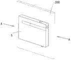
图2是示出图1所示的光纤接续组件安装在安装壁上时处于收缩状态的侧视图,其中接续盒未固定在安装壁上;Fig. 2 is a side view showing the contracted state of the optical fiber splicing assembly shown in Fig. 1 when it is installed on the installation wall, wherein the splice box is not fixed on the installation wall;
图3是示出图2所示的光纤接续组件从安装壁后部观察的立体示意图;Fig. 3 is a schematic perspective view showing the optical fiber splicing assembly shown in Fig. 2 viewed from the rear of the installation wall;
图4是示出图2所示的光纤接续组件从安装壁前部观察的立体示意图,其中接续盒已固定在安装壁上;Fig. 4 is a schematic perspective view showing the optical fiber splicing assembly shown in Fig. 2 viewed from the front of the installation wall, wherein the splice box has been fixed on the installation wall;
图5是示出图4所示的光纤接续组件在盖体已除去时的立体示意图;Fig. 5 is a schematic perspective view showing the optical fiber splicing assembly shown in Fig. 4 when the cover has been removed;
图6是示出图1所示的光纤接续组件安装在安装壁上时处于张开状态的侧视图;Fig. 6 is a side view showing that the optical fiber splicing assembly shown in Fig. 1 is in an unfolded state when it is installed on the installation wall;
图7是示出图6所示的光纤接续组件从安装壁后部观察的立体示意图;Fig. 7 is a schematic perspective view showing the optical fiber splicing assembly shown in Fig. 6 viewed from the rear of the installation wall;
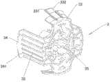
图8是示出本发明的光纤接续组件的安装装置在一个方向观察的立体示意图;Fig. 8 is a schematic perspective view showing the installation device of the optical fiber splicing assembly of the present invention viewed from one direction;
图9是示出本发明的光纤接续组件的安装装置在另一个方向观察的立体示意图;Fig. 9 is a schematic perspective view showing the installation device of the optical fiber splicing assembly of the present invention viewed from another direction;
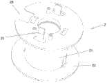
图10是示出本发明的光纤接续组件的卷轴的立体示意图;Fig. 10 is a schematic perspective view showing the reel of the optical fiber splicing assembly of the present invention;
图11是示出图10所示的卷轴的一种剖视图;Figure 11 is a cross-sectional view showing the reel shown in Figure 10;
图12是示出本发明的光纤接续组件的中间轴的立体示意图;Fig. 12 is a schematic perspective view showing the intermediate shaft of the optical fiber splicing assembly of the present invention;
图13是示出图12所示的中间轴的一种剖视图;Fig. 13 is a cross-sectional view showing the intermediate shaft shown in Fig. 12;
图14是示出图4所示的本发明的光纤接续组件沿A-A线的剖视图;Fig. 14 is a cross-sectional view showing the fiber splicing assembly of the present invention shown in Fig. 4 along line A-A;
图15是示出图6所示的本发明的光纤接续组件沿B-B线的剖视图;Fig. 15 is a sectional view showing the optical fiber splicing assembly of the present invention shown in Fig. 6 along line B-B;
图16是示出图6所示的本发明的光纤接续组件沿C-C线的剖视图;以及Figure 16 is a cross-sectional view showing the optical fiber splicing assembly of the present invention shown in Figure 6 along line C-C; and
图17是示出图6所示的本发明的光纤接续组件沿D-D线的剖视图。Fig. 17 is a cross-sectional view showing the fiber splicing assembly of the present invention shown in Fig. 6 along the line D-D.
具体实施方式Detailed ways
虽然将参照含有本发明的较佳实施例的附图充分描述本发明,但在此描述之前应了解本领域的普通技术人员可修改本文中所描述的发明,同时获得本发明的技术效果。因此,须了解以上的描述对本领域的普通技术人员而言为一广泛的揭示,且其内容不在于限制本发明所描述的示例性实施例。附图中相同的附图标记表示相同的组成部分。While the present invention will be fully described with reference to the accompanying drawings containing preferred embodiments of the invention, it should be understood before proceeding that those skilled in the art may modify the invention described herein while obtaining the technical effects of the present invention. Therefore, it should be understood that the above description is a broad disclosure for those skilled in the art, and its content is not intended to limit the described exemplary embodiments of the present invention. The same reference numerals in the figures denote the same components.
图1是示出根据本发明的光纤接续组件的一种实例性实施例的分解示意图。根据本发明的总体构思的光纤接续组件100可实现对不同光缆的多条光纤之间的接续。本发明的光纤接续组件100可安装到设有安装孔201(参见图6)安装壁200上,包括:接续面板1和光纤存储装置10。如图1和5所示,接续面板1具有一般接续面板的构造,并包括用于实现光纤接续的光纤接续装置11、用于安装光纤接续装置11的安装组件13、以及存储冗余光纤的存储装置12。接续面板1上还安装盖体5。FIG. 1 is an exploded schematic view showing an exemplary embodiment of an optical fiber splicing assembly according to the present invention. The optical
参见图1-7,根据本发明的光纤接续组件100的一种示例性实施例,接续面板1的背面可分离地安装在安装壁200的正面,并且接续面板1的正面被构造成安装用于实现光纤接续的光纤接续装置11。光纤存储装置10至少部分容纳于安装孔201中,并且光纤存储装置10的一端与接续面板1可拆卸地安装在一起。1-7, according to an exemplary embodiment of the optical
在一种示例性实施例中,光纤存储装置10包括卷轴2,卷轴(reel)2可拆卸地安装在接续面板2的背面,被接续光缆或光纤例如以卷绕的方式存储在卷轴2上。光纤存储装置10还包括支撑架3,卷轴2安装于支撑架3上,支撑架3用于将光纤存储装置10安装在安装壁200上,例如安装在安装臂200的背面。支撑架3包括具有自由端的支撑轴31(参见图9),卷轴2与支撑轴31可相对移动地套接在一起,并且卷轴2可以相对于支撑轴31沿轴向从位于安装孔201中的收缩状态移动至露于安装孔201之外的伸展状态,当卷轴2处于伸展状态时,安装人员可以从安装壁200外部将存储在所述卷轴上的光缆或者光纤拉出。进一步地,卷轴2相对于支撑轴31可转动地套接在一起并容纳在支撑架3中。In an exemplary embodiment, the optical
本发明的光纤接续组件100的光纤存储装置进一步包括中间轴4,所述中间轴的第一端与所述卷轴2可相对轴向移动地连接,所述中间轴的第二端与所述支撑轴31可相对轴向方向(卷轴的收缩和伸展方向)移动地连接。通过调整所述中间轴4的长度,可以帮助安装人员将卷轴2拉至安装壁外最便于绕接冗余光纤的位置。在一种示例性实施例中,卷轴2被构造成能够在支撑轴31上穿过安装孔201(参见图6)从安装壁200的背面移动到安装壁200的正面,以进入伸展状态。中间轴4在轴向方向上可滑动地结合到支撑轴31,并且中间轴4的第一端(图1中的左端,图13中的上端)可转动地结合到卷轴2。The optical fiber storage device of the optical
进一步地,中间轴4通过型面配合的方式可滑动地结合到支撑轴31,即中间轴和支撑轴31具有彼此在形状上配合的结构,这样可以阻止中间轴4相对于支撑轴31转动。Further, the
如图1、12、13所示,中间轴4为大致的套筒结构并可滑动地套接在转动轴31上。进一步地,中间轴4的内表面和支撑轴31的外表面中的一个上设有沿轴向方向延伸的多个滑动凹槽,在另一个上设有分别与凹槽滑动地配合的多个滑动凸起。在一种示例性实施例中,支撑轴31的外表面上设有滑动凹槽,中间轴4的内表面的第二端(图13中的下端)附近设有滑动凸起。但可以理解,在一种替换的实施例中,支撑轴31的外表面上设有滑动凸起,而中间轴4的内表面上设有滑动凹槽。这样,中间轴4可以通过滑动凸起在支撑轴31的滑动凹槽内沿轴向方向滑动,但由于滑动凸起的阻止作用而不能相对于支撑轴31转动。As shown in FIGS. 1 , 12 , and 13 , the
细细而言,参见图6、8、9、12、13、15和16,设置在支撑轴31上的滑动凹槽包括至少一个第一滑动凹槽311和至少一个第二滑动凹槽316。设置在中间轴4的内表面上的滑动凸起包括至少一个第一滑动凸起42和至少一个第二滑动凸起43。在将卷轴2从收缩状态改变到伸展状态或者相反的过程中,第一滑动凸起42和第二滑动凸起43分别在第一滑动凹槽311和第二滑动凹槽316内滑动,同时阻止中间轴4相对于支撑轴31转动。第一滑动凹槽311在靠近支撑轴31的自由端(顶端)的位置设有第一阻挡凸起312,第二滑动凹槽316在靠近支撑轴31的自由端的位置设有第一限制凸起313。这样,在卷轴2从收缩状态转换到伸展状态时,所述第一阻挡凸起312与第一滑动凸起42以锁定方式配合以阻止中间轴4脱离支撑轴3的自由端,同时,所述第一限制凸起313与第二滑动凸起43以卡扣方式配合以限制中间轴4沿与原来的滑动方向(图16向上的方向)相反的方向(图16向下的方向)滑动。In detail, referring to FIGS. 6 , 8 , 9 , 12 , 13 , 15 and 16 , the sliding grooves provided on the
参见图13和15,第一阻挡凸起312与第一滑动凸起42都具有与轴向方向大致垂直的配合表面,因此当中间轴4滑动到使得第一阻挡凸起312与第一滑动凸起42配合时,除非破坏第一阻挡凸起312与第一滑动凸起42的结构,无论施加多大的力,中间轴4都将不能再继续沿原来的方向进一步地滑动。因此,第一阻挡凸起312与第一滑动凸起42之间采用“锁定方式配合”。Referring to Figures 13 and 15, the
另一方面,参见图13和16,第一限制凸起313与第二滑动凸起43都具有与轴向方向倾斜的配合表面。因此,在中间轴4从收缩状态到伸展状态的滑动过程中,由于施加了较大的力,允许第二滑动凸起43利用其自身的弹性而越过第一限制凸起313,同时形成伸展状态。之后,所施加的力除去,第一限制凸起313将限制第二滑动凸起43沿与原来的滑动方向相反的方向滑动,即在图16中限制中间轴向下滑动。但可以理解,如果施加较大的力,将解除第一限制凸起313对第二滑动凸起43的限制,允许中间轴4仍然向下滑动。因此,第一限制凸起313与第二滑动凸起43之间采用“卡扣方式配合”。On the other hand, referring to FIGS. 13 and 16 , both the first restricting
在上面描述了第一滑动凸起42和第二滑动凸起43设置在不同的滑动凹槽中的实施例,但本发明并不局限于此。在一种可替换的实施例中,每个滑动凹槽在靠近支撑轴的自由端的位置设有第一阻挡凸起和第一限制凸起,在卷轴2从收缩状态转换到伸展状态时,所述第一阻挡凸起与所述滑动凸起以锁定方式配合以阻止所述中间轴脱离所述自由端,所述第一限制凸起与所述滑动凸起以卡扣方式配合以限制所述中间轴沿与原来的滑动方向相反的方向滑动。The embodiment in which the first sliding
根据本发明的光纤接续组件100的进一步地的实施例,参见图10和11,卷轴2包括筒体21和设置在筒体21两端的凸缘22,在凸缘22上设有用于光缆或光纤的切口26。中间轴4的第一端(图12和13中的上端)在轴向方向上可移动地结合到所述卷轴2的筒体21内。参见图17,筒体21的第一端(图10和11中的下端)的内侧设有环形凸起24,所述环形凸起24与中间轴4第一端附近的外表面可转动地配合。参见图10、11和14,支撑架2的筒体21上还延伸形成有用于以卡扣方式固定到接续面板1上的结合部25。According to a further embodiment of the optical
进一步地,再次参见图12、13、15和16,在中间轴4的第一端设有多个第二阻挡凸起44,所述第二阻挡凸起44与环形凸起24的远离筒体21的第一端的侧缘241以锁定方式配合以在卷轴2处于伸展状态时阻止卷轴2脱离所述中间轴的第一端。第二阻挡凸起44和侧缘241都具有与轴向方向大致垂直的配合表面。另一方面,在环形凸起24上设有多个第二限制凸起242,在中间轴4的外表面上设有环形凹槽45。在卷轴2从收缩状态转换到伸展状态时,第二限制凸起242与环形凹槽45以卡扣方式配合以限制卷轴2沿与原来的滑动方向相反的方向滑动。Further, referring to FIGS. 12 , 13 , 15 and 16 again, a plurality of second blocking
更进一步的,参见图10、11和14,筒体21的第二端(图10和11中的上端)的内侧设有环形裙部(skirt)23,所述环形裙部23与筒体21的内壁之间具有间隙232。在卷轴2处于收缩状态时,环形裙部23位于中间轴4的第二端与支撑轴31的自由端之间,使得卷轴2能够相对于支撑轴31和中间轴4转动。环形裙部23上设有环形限制凸起231,支撑轴31的自由端设有第三限制凸起315(参见9),环形限制凸起231与第三限制凸起315以卡扣方式配合以在卷轴2处于收缩状态时限制卷轴2远离中间轴4移动,从而使卷轴2能够稳定地容纳在支撑架3内。Further, referring to Fig. 10, 11 and 14, the inner side of the second end (upper end among Fig. 10 and 11) of the
根据本发明的光纤接续组件100的进一步的示例性实施例,支撑架3包括基座35和多个支撑臂32。支撑轴35被支撑在基座35上。多个支撑臂32从支撑臂32的边缘延伸,支撑架3通过支撑臂32安装到安装壁200上。进一步地,支撑臂32的自由端设有能够结合到安装壁200的正面的凸缘34。凸缘34上设有能够插入到支撑壁200内的固定销341。支撑架进一步包括从所述支撑臂的边缘延伸的多组定位装置33,定位装置33与支撑臂32交替布置。每组定位装置33包括多个定位弹片331,定位弹片331具有不同的长度。另外,定位弹片331上设有定位凸起332。这样,参见图3和7,当将本发明的光纤接续组件100安装在安装壁200上时,将支撑臂32稍微收缩并从安装壁200的背面穿过安装孔201插到安装壁200的正面,并利用凸缘34上的固定销341将凸缘34固定在安装壁的正面。同时,定位装置33的定位弹片331抵靠在安装壁的背面。如果安装壁200的厚度较大,这将长度较长的定位弹片331插入到安装孔201中,同时使定位弹片331上的定位凸起332抵靠在安装壁200的背面,从而将支撑架3稳定地安装在安装壁200上。According to a further exemplary embodiment of the optical
在一种可替换的实施例中,支撑臂具有弹性,所述支撑臂所在的圆周的外径可大于安装孔201的直径,当支撑臂装入安装孔201中时发生弹性形变并通过对安装孔201施加的弹性应力将所述支撑臂固定于安装孔201中。In an alternative embodiment, the support arm has elasticity, and the outer diameter of the circumference where the support arm is located may be larger than the diameter of the
参见图9和14,在进一步的实施例中,基座35上设有多个向内凸起的弹性件36。参见图2和5,在接续面板1上设有两个安装孔14。当卷轴2容纳在支撑架3中但接续面板1没有固定在安装壁200上的情况下,卷轴2仍然可以相对于支撑轴31转动。在卷轴2转动过程中,由于弹性件36的作用,接续面板1的背面将与安装壁200的正面保持一定的距离,这样可以防止安装壁200的表面不会由于接续面板1的转动而被划伤,同时保持接续面板1能够平稳地转动。接续面板1上设有至少两个安装孔14,用于配合镙钉(未示出)将接续面板1固定于安装壁200上。当将接续面板1利用通过安装孔14安装在安装壁200上后,如图3-5所述,由于弹片件36的弹性作用,因此通过螺栓的拧紧力,可以消除接续面板1的背面与安装壁200的正面之间的缝隙,从而将接续面板1稳定地安装在安装壁200上。Referring to FIGS. 9 and 14 , in a further embodiment, the
在上面虽然描述了中间轴4相对于支撑轴31不转动,而卷轴2相对于中间轴4转动的实施例,但本发明并不局限于此。在本发明的光纤接续组件的另一种实施例中,中间轴的第一端可转动地并在轴向方向上可滑动地结合到所述支撑轴,而中间轴的第二端在轴向方向上可移动地结合到所述卷轴。Although the embodiment in which the
在进一步可替换的实施例中,卷轴可以直接可滑动地连接到支撑轴上。例如,卷轴的内表面和支撑轴的外表面中的一个上设有沿轴向方向延伸的多个滑动凹槽,在另一个上设有分别与凹槽滑动地配合的多个滑动凸起。可替换地,卷轴的外表面和支撑轴的内表面中的一个上设有沿轴向方向延伸的多个滑动凹槽,在另一个上设有分别与凹槽滑动地配合的多个滑动凸起。In a further alternative embodiment, the reel may be slidably connected directly to the support shaft. For example, one of the inner surface of the reel shaft and the outer surface of the support shaft is provided with a plurality of sliding grooves extending in the axial direction, and the other is provided with a plurality of sliding protrusions respectively slidably engaged with the grooves. Alternatively, one of the outer surface of the reel and the inner surface of the support shaft is provided with a plurality of sliding grooves extending in the axial direction, and the other is provided with a plurality of sliding protrusions respectively slidably fitted with the grooves. rise.
根据本发明的上述各种实施例的光纤接续组件,卷轴可收缩到安装壁背面内并且可以伸出到安装壁正面,方便了对冗余的光缆或光纤进行维护、管理和操作。在安装接续面板时,可以将光缆或光纤预先存放于卷轴中。操作时,可将光纤从卷轴中拉出后对接到其他装置上,无需计算需要的光纤长度,实现了快速对接。用于安装卷轴的支撑架可安装于不同厚度的石膏板之类的安装壁上。另外,卷轴可以在容纳在支撑架内的收缩状态下在支撑架内转动,也可以在从支撑架中伸展到安装壁正面的伸展状态下底座相对于支撑轴转动,从而可以将光纤从卷轴中拉出。进一步地,由于卷轴和支撑架安装在安装壁的背面,只有较薄的接续面板突出在安装壁的正面,节省了空间,且具有良好的外管。According to the optical fiber splicing assembly of various embodiments of the present invention, the reel can be retracted into the back of the installation wall and extended to the front of the installation wall, which facilitates the maintenance, management and operation of redundant optical cables or optical fibers. Fiber optic cables or fibers can be pre-stored in reels when splice panels are installed. During operation, the optical fiber can be pulled out from the reel and then docked to other devices without calculating the required fiber length, realizing fast docking. The support frame for mounting the reel can be mounted on a mounting wall such as plasterboard of different thicknesses. In addition, the reel can be rotated in the support frame in the retracted state contained in the support frame, and the base can be rotated relative to the support shaft in the extended state extending from the support frame to the front of the installation wall, so that the optical fiber can be removed from the reel. pull out. Further, since the reel and the supporting frame are installed at the back of the installation wall, only the thinner connecting panel protrudes from the front of the installation wall, which saves space and has a good outer tube.
本领域的技术人员可以理解,上面所描述的实施例都是示例性的,并且本领域的技术人员可以对其进行改进,各种实施例中所描述的结构在不发生结构或者原理方面的冲突的情况下可以进行自由组合,从而在解决本发明的技术问题的基础上,实现更多种光纤接续组件。Those skilled in the art can understand that the above-described embodiments are exemplary, and those skilled in the art can improve them, and the structures described in various embodiments do not conflict with each other in terms of structure or principle Under the circumstances, free combination can be carried out, so as to realize more kinds of optical fiber splicing assemblies on the basis of solving the technical problem of the present invention.
在详细说明本发明的较佳实施例之后,熟悉本领域的技术人员可清楚的了解,在不脱离随附权利要求的保护范围与精神下可进行各种变化与改变,且本发明亦不受限于说明书中所举示例性实施例的实施方式。After describing the preferred embodiments of the present invention in detail, those skilled in the art can clearly understand that various changes and changes can be made without departing from the scope and spirit of the appended claims, and the present invention is not limited by Implementation is limited to the exemplary embodiments set forth in the specification.
Claims (32)
Priority Applications (8)
| Application Number | Priority Date | Filing Date | Title |
|---|---|---|---|
| CN201611163812.3ACN106707434B (en) | 2012-08-07 | 2012-08-07 | Fibre junction component |
| CN201210280488.9ACN103576266B (en) | 2012-08-07 | 2012-08-07 | Fiber optic connector |
| AU2013301184AAU2013301184B2 (en) | 2012-08-07 | 2013-08-02 | Fiber optic splicing assembly |
| JP2015525984AJP6313303B2 (en) | 2012-08-07 | 2013-08-02 | Optical fiber splicing assembly |
| NZ705741ANZ705741A (en) | 2012-08-07 | 2013-08-02 | Fiber optic splicing assembly |
| EP13765517.1AEP2883100B1 (en) | 2012-08-07 | 2013-08-02 | Fiber optic splicing assembly |
| PCT/IB2013/056339WO2014024105A1 (en) | 2012-08-07 | 2013-08-02 | Fiber optic splicing assembly |
| US14/616,198US9594217B2 (en) | 2012-08-07 | 2015-02-06 | Fiber optic splicing assembly |
Applications Claiming Priority (1)
| Application Number | Priority Date | Filing Date | Title |
|---|---|---|---|
| CN201210280488.9ACN103576266B (en) | 2012-08-07 | 2012-08-07 | Fiber optic connector |
Related Child Applications (1)
| Application Number | Title | Priority Date | Filing Date |
|---|---|---|---|
| CN201611163812.3ADivisionCN106707434B (en) | 2012-08-07 | 2012-08-07 | Fibre junction component |
Publications (2)
| Publication Number | Publication Date |
|---|---|
| CN103576266Atrue CN103576266A (en) | 2014-02-12 |
| CN103576266B CN103576266B (en) | 2017-01-18 |
Family
ID=49223832
Family Applications (2)
| Application Number | Title | Priority Date | Filing Date |
|---|---|---|---|
| CN201611163812.3AExpired - Fee RelatedCN106707434B (en) | 2012-08-07 | 2012-08-07 | Fibre junction component |
| CN201210280488.9AExpired - Fee RelatedCN103576266B (en) | 2012-08-07 | 2012-08-07 | Fiber optic connector |
Family Applications Before (1)
| Application Number | Title | Priority Date | Filing Date |
|---|---|---|---|
| CN201611163812.3AExpired - Fee RelatedCN106707434B (en) | 2012-08-07 | 2012-08-07 | Fibre junction component |
Country Status (7)
| Country | Link |
|---|---|
| US (1) | US9594217B2 (en) |
| EP (1) | EP2883100B1 (en) |
| JP (1) | JP6313303B2 (en) |
| CN (2) | CN106707434B (en) |
| AU (1) | AU2013301184B2 (en) |
| NZ (1) | NZ705741A (en) |
| WO (1) | WO2014024105A1 (en) |
Cited By (1)
| Publication number | Priority date | Publication date | Assignee | Title |
|---|---|---|---|---|
| CN113566868A (en)* | 2021-08-27 | 2021-10-29 | 国网浙江省电力有限公司信息通信分公司 | Intelligent monitoring device for splice box |
Families Citing this family (7)
| Publication number | Priority date | Publication date | Assignee | Title |
|---|---|---|---|---|
| WO2015067645A1 (en) | 2013-11-06 | 2015-05-14 | Adc Czech Republic, S.R.O. | Fiber termination point with overlength storage |
| US10754115B2 (en) | 2015-04-22 | 2020-08-25 | CommScope Connectivity Belgium BVBA | Deploying optical fibers within a multi-dwelling unit |
| EP3326016B1 (en)* | 2015-07-23 | 2022-09-07 | Commscope Technologies LLC | Cable spool re-orientation device for a wall box |
| US10162143B1 (en)* | 2017-09-21 | 2018-12-25 | Ofs Fitel, Llc | Behind-the-wall fiber spool module |
| DE102019106951A1 (en)* | 2019-03-19 | 2020-09-24 | Wilhelm Rutenbeck Gmbh & Co. Kg | Device for receiving and securely holding the wires of an optical fiber |
| CN111722335B (en)* | 2020-06-09 | 2022-09-23 | 华为技术有限公司 | Optical cable storage device |
| WO2023097582A1 (en)* | 2021-12-01 | 2023-06-08 | 山东微感光电子有限公司 | Distributed optical fiber temperature measurement device, and photovoltaic panel temperature measurement system and method |
Citations (5)
| Publication number | Priority date | Publication date | Assignee | Title |
|---|---|---|---|---|
| US20080011514A1 (en)* | 2006-07-14 | 2008-01-17 | Tenvera, Inc. | Optical Fiber Distribution Apparatus and Method |
| US20080315030A1 (en)* | 2007-06-22 | 2008-12-25 | Furukawa Electric North America, Inc. | Fiber optic rapid spooling tool |
| US20100074587A1 (en)* | 2008-09-16 | 2010-03-25 | Todd Loeffelholz | Modular fiber optic enclosure with external cable spool |
| CN202583564U (en)* | 2012-05-03 | 2012-12-05 | 泰科电子(上海)有限公司 | Optical fiber splice box |
| CN202837598U (en)* | 2012-08-07 | 2013-03-27 | 泰科电子(上海)有限公司 | Optical fiber connection assembly |
Family Cites Families (7)
| Publication number | Priority date | Publication date | Assignee | Title |
|---|---|---|---|---|
| US6591053B2 (en)* | 2000-03-08 | 2003-07-08 | Panduit Corp. | Fiber optic wall mount cabinet |
| JP4213367B2 (en)* | 2001-06-20 | 2009-01-21 | 株式会社フジクラ | Optical component module |
| JP2004303629A (en)* | 2003-03-31 | 2004-10-28 | Daiwa House Ind Co Ltd | Structure of embedded type outlet |
| JP2005024978A (en)* | 2003-07-03 | 2005-01-27 | Mirai Ind Co Ltd | Structure of cable drawing-out section, cable drawing-out section forming device, winding member, mounting frame, and plate |
| CN101221270B (en)* | 2007-01-13 | 2012-01-11 | 古河电子北美公司 | Wall-mountable optical fiber and cable management apparatus |
| US7715679B2 (en)* | 2007-05-07 | 2010-05-11 | Adc Telecommunications, Inc. | Fiber optic enclosure with external cable spool |
| US7756379B2 (en)* | 2007-08-06 | 2010-07-13 | Adc Telecommunications, Inc. | Fiber optic enclosure with internal cable spool |
- 2012
- 2012-08-07CNCN201611163812.3Apatent/CN106707434B/ennot_activeExpired - Fee Related
- 2012-08-07CNCN201210280488.9Apatent/CN103576266B/ennot_activeExpired - Fee Related
- 2013
- 2013-08-02JPJP2015525984Apatent/JP6313303B2/enactiveActive
- 2013-08-02WOPCT/IB2013/056339patent/WO2014024105A1/enactiveApplication Filing
- 2013-08-02EPEP13765517.1Apatent/EP2883100B1/enactiveActive
- 2013-08-02NZNZ705741Apatent/NZ705741A/ennot_activeIP Right Cessation
- 2013-08-02AUAU2013301184Apatent/AU2013301184B2/enactiveActive
- 2015
- 2015-02-06USUS14/616,198patent/US9594217B2/enactiveActive
Patent Citations (5)
| Publication number | Priority date | Publication date | Assignee | Title |
|---|---|---|---|---|
| US20080011514A1 (en)* | 2006-07-14 | 2008-01-17 | Tenvera, Inc. | Optical Fiber Distribution Apparatus and Method |
| US20080315030A1 (en)* | 2007-06-22 | 2008-12-25 | Furukawa Electric North America, Inc. | Fiber optic rapid spooling tool |
| US20100074587A1 (en)* | 2008-09-16 | 2010-03-25 | Todd Loeffelholz | Modular fiber optic enclosure with external cable spool |
| CN202583564U (en)* | 2012-05-03 | 2012-12-05 | 泰科电子(上海)有限公司 | Optical fiber splice box |
| CN202837598U (en)* | 2012-08-07 | 2013-03-27 | 泰科电子(上海)有限公司 | Optical fiber connection assembly |
Cited By (1)
| Publication number | Priority date | Publication date | Assignee | Title |
|---|---|---|---|---|
| CN113566868A (en)* | 2021-08-27 | 2021-10-29 | 国网浙江省电力有限公司信息通信分公司 | Intelligent monitoring device for splice box |
Also Published As
| Publication number | Publication date |
|---|---|
| AU2013301184A1 (en) | 2015-03-26 |
| US9594217B2 (en) | 2017-03-14 |
| JP6313303B2 (en) | 2018-04-18 |
| EP2883100B1 (en) | 2019-05-01 |
| WO2014024105A1 (en) | 2014-02-13 |
| CN103576266B (en) | 2017-01-18 |
| JP2015525907A (en) | 2015-09-07 |
| NZ705741A (en) | 2017-04-28 |
| AU2013301184B2 (en) | 2016-12-22 |
| CN106707434A (en) | 2017-05-24 |
| CN106707434B (en) | 2019-06-11 |
| EP2883100A1 (en) | 2015-06-17 |
| US20150153513A1 (en) | 2015-06-04 |
Similar Documents
| Publication | Publication Date | Title |
|---|---|---|
| CN103576266B (en) | Fiber optic connector | |
| US20220326465A1 (en) | Cable mounting clamps | |
| US20190233248A1 (en) | Transformable cable reels and related assemblies and methods | |
| US20130094828A1 (en) | Fiber optic distribution terminal and method of deploying fiber distribution cable | |
| US11231557B2 (en) | Cable spool re-orientation device for a wall box | |
| US9329352B2 (en) | Slack cable storage apparatus | |
| CN107076953A (en) | Multi-position Telecom Rack | |
| EP3460552B1 (en) | Behind-the-wall fiber spool module | |
| US11947179B2 (en) | Reel enclosures | |
| US10182511B1 (en) | Extendable cable management frame | |
| CN202837598U (en) | Optical fiber connection assembly | |
| KR101400752B1 (en) | Fiber distribution case | |
| KR102053788B1 (en) | Cleaning tool | |
| US20110168589A1 (en) | Case structure and optical device having such case structure | |
| BR102012014953A2 (en) | OPTICAL FIBER TRAY AND ASSEMBLY UNDERSTANDING A FIRST OPTICAL FIBER TRAY AND A SECOND OPTICAL FIBER TRAY | |
| CN104714279A (en) | Fixing device for optical fiber connectors | |
| EP3789802B1 (en) | Adapter device for fiber optical connections | |
| US20210181450A1 (en) | Fiber optic management device | |
| CN106707418A (en) | Auxiliary equipment of fiber connection | |
| JP2019082588A (en) | Adapter backlash prevention mechanism for optical connector |
Legal Events
| Date | Code | Title | Description |
|---|---|---|---|
| C06 | Publication | ||
| PB01 | Publication | ||
| SE01 | Entry into force of request for substantive examination | ||
| SE01 | Entry into force of request for substantive examination | ||
| C41 | Transfer of patent application or patent right or utility model | ||
| TA01 | Transfer of patent application right | Effective date of registration:20160801 Address after:200131 China (Shanghai) site of A15 88 B1 layer Taigu road free trade zone Applicant after:ADC TELECOMMUNICATIONS (SHANGHAI) DISTRIBUTION Co.,Ltd. Address before:200131 Shanghai city Hedan Waigaoqiao Free Trade Zone No. 142 first floor Applicant before:Tyco Electronics (Shanghai) Co.,Ltd. | |
| C14 | Grant of patent or utility model | ||
| GR01 | Patent grant | ||
| CF01 | Termination of patent right due to non-payment of annual fee | ||
| CF01 | Termination of patent right due to non-payment of annual fee | Granted publication date:20170118 |