CN103568861A - Low cost charger circuit with pre-charge functionality - Google Patents
Low cost charger circuit with pre-charge functionalityDownload PDFInfo
- Publication number
- CN103568861A CN103568861ACN201310306677.3ACN201310306677ACN103568861ACN 103568861 ACN103568861 ACN 103568861ACN 201310306677 ACN201310306677 ACN 201310306677ACN 103568861 ACN103568861 ACN 103568861A
- Authority
- CN
- China
- Prior art keywords
- voltage bus
- converter
- charger
- coupled
- ress
- Prior art date
- Legal status (The legal status is an assumption and is not a legal conclusion. Google has not performed a legal analysis and makes no representation as to the accuracy of the status listed.)
- Granted
Links
Images


Classifications
- B—PERFORMING OPERATIONS; TRANSPORTING
- B60—VEHICLES IN GENERAL
- B60L—PROPULSION OF ELECTRICALLY-PROPELLED VEHICLES; SUPPLYING ELECTRIC POWER FOR AUXILIARY EQUIPMENT OF ELECTRICALLY-PROPELLED VEHICLES; ELECTRODYNAMIC BRAKE SYSTEMS FOR VEHICLES IN GENERAL; MAGNETIC SUSPENSION OR LEVITATION FOR VEHICLES; MONITORING OPERATING VARIABLES OF ELECTRICALLY-PROPELLED VEHICLES; ELECTRIC SAFETY DEVICES FOR ELECTRICALLY-PROPELLED VEHICLES
- B60L3/00—Electric devices on electrically-propelled vehicles for safety purposes; Monitoring operating variables, e.g. speed, deceleration or energy consumption
- B60L3/0092—Electric devices on electrically-propelled vehicles for safety purposes; Monitoring operating variables, e.g. speed, deceleration or energy consumption with use of redundant elements for safety purposes
- B—PERFORMING OPERATIONS; TRANSPORTING
- B60—VEHICLES IN GENERAL
- B60L—PROPULSION OF ELECTRICALLY-PROPELLED VEHICLES; SUPPLYING ELECTRIC POWER FOR AUXILIARY EQUIPMENT OF ELECTRICALLY-PROPELLED VEHICLES; ELECTRODYNAMIC BRAKE SYSTEMS FOR VEHICLES IN GENERAL; MAGNETIC SUSPENSION OR LEVITATION FOR VEHICLES; MONITORING OPERATING VARIABLES OF ELECTRICALLY-PROPELLED VEHICLES; ELECTRIC SAFETY DEVICES FOR ELECTRICALLY-PROPELLED VEHICLES
- B60L3/00—Electric devices on electrically-propelled vehicles for safety purposes; Monitoring operating variables, e.g. speed, deceleration or energy consumption
- B60L3/0023—Detecting, eliminating, remedying or compensating for drive train abnormalities, e.g. failures within the drive train
- B60L3/0046—Detecting, eliminating, remedying or compensating for drive train abnormalities, e.g. failures within the drive train relating to electric energy storage systems, e.g. batteries or capacitors
- B—PERFORMING OPERATIONS; TRANSPORTING
- B60—VEHICLES IN GENERAL
- B60L—PROPULSION OF ELECTRICALLY-PROPELLED VEHICLES; SUPPLYING ELECTRIC POWER FOR AUXILIARY EQUIPMENT OF ELECTRICALLY-PROPELLED VEHICLES; ELECTRODYNAMIC BRAKE SYSTEMS FOR VEHICLES IN GENERAL; MAGNETIC SUSPENSION OR LEVITATION FOR VEHICLES; MONITORING OPERATING VARIABLES OF ELECTRICALLY-PROPELLED VEHICLES; ELECTRIC SAFETY DEVICES FOR ELECTRICALLY-PROPELLED VEHICLES
- B60L3/00—Electric devices on electrically-propelled vehicles for safety purposes; Monitoring operating variables, e.g. speed, deceleration or energy consumption
- B60L3/04—Cutting off the power supply under fault conditions
- B—PERFORMING OPERATIONS; TRANSPORTING
- B60—VEHICLES IN GENERAL
- B60L—PROPULSION OF ELECTRICALLY-PROPELLED VEHICLES; SUPPLYING ELECTRIC POWER FOR AUXILIARY EQUIPMENT OF ELECTRICALLY-PROPELLED VEHICLES; ELECTRODYNAMIC BRAKE SYSTEMS FOR VEHICLES IN GENERAL; MAGNETIC SUSPENSION OR LEVITATION FOR VEHICLES; MONITORING OPERATING VARIABLES OF ELECTRICALLY-PROPELLED VEHICLES; ELECTRIC SAFETY DEVICES FOR ELECTRICALLY-PROPELLED VEHICLES
- B60L53/00—Methods of charging batteries, specially adapted for electric vehicles; Charging stations or on-board charging equipment therefor; Exchange of energy storage elements in electric vehicles
- B60L53/10—Methods of charging batteries, specially adapted for electric vehicles; Charging stations or on-board charging equipment therefor; Exchange of energy storage elements in electric vehicles characterised by the energy transfer between the charging station and the vehicle
- B60L53/14—Conductive energy transfer
- H—ELECTRICITY
- H02—GENERATION; CONVERSION OR DISTRIBUTION OF ELECTRIC POWER
- H02J—CIRCUIT ARRANGEMENTS OR SYSTEMS FOR SUPPLYING OR DISTRIBUTING ELECTRIC POWER; SYSTEMS FOR STORING ELECTRIC ENERGY
- H02J7/00—Circuit arrangements for charging or depolarising batteries or for supplying loads from batteries
- H02J7/0013—Circuit arrangements for charging or depolarising batteries or for supplying loads from batteries acting upon several batteries simultaneously or sequentially
- B—PERFORMING OPERATIONS; TRANSPORTING
- B60—VEHICLES IN GENERAL
- B60L—PROPULSION OF ELECTRICALLY-PROPELLED VEHICLES; SUPPLYING ELECTRIC POWER FOR AUXILIARY EQUIPMENT OF ELECTRICALLY-PROPELLED VEHICLES; ELECTRODYNAMIC BRAKE SYSTEMS FOR VEHICLES IN GENERAL; MAGNETIC SUSPENSION OR LEVITATION FOR VEHICLES; MONITORING OPERATING VARIABLES OF ELECTRICALLY-PROPELLED VEHICLES; ELECTRIC SAFETY DEVICES FOR ELECTRICALLY-PROPELLED VEHICLES
- B60L2210/00—Converter types
- B60L2210/10—DC to DC converters
- B60L2210/12—Buck converters
- B—PERFORMING OPERATIONS; TRANSPORTING
- B60—VEHICLES IN GENERAL
- B60L—PROPULSION OF ELECTRICALLY-PROPELLED VEHICLES; SUPPLYING ELECTRIC POWER FOR AUXILIARY EQUIPMENT OF ELECTRICALLY-PROPELLED VEHICLES; ELECTRODYNAMIC BRAKE SYSTEMS FOR VEHICLES IN GENERAL; MAGNETIC SUSPENSION OR LEVITATION FOR VEHICLES; MONITORING OPERATING VARIABLES OF ELECTRICALLY-PROPELLED VEHICLES; ELECTRIC SAFETY DEVICES FOR ELECTRICALLY-PROPELLED VEHICLES
- B60L2210/00—Converter types
- B60L2210/10—DC to DC converters
- B60L2210/14—Boost converters
- B—PERFORMING OPERATIONS; TRANSPORTING
- B60—VEHICLES IN GENERAL
- B60L—PROPULSION OF ELECTRICALLY-PROPELLED VEHICLES; SUPPLYING ELECTRIC POWER FOR AUXILIARY EQUIPMENT OF ELECTRICALLY-PROPELLED VEHICLES; ELECTRODYNAMIC BRAKE SYSTEMS FOR VEHICLES IN GENERAL; MAGNETIC SUSPENSION OR LEVITATION FOR VEHICLES; MONITORING OPERATING VARIABLES OF ELECTRICALLY-PROPELLED VEHICLES; ELECTRIC SAFETY DEVICES FOR ELECTRICALLY-PROPELLED VEHICLES
- B60L2270/00—Problem solutions or means not otherwise provided for
- B60L2270/20—Inrush current reduction, i.e. avoiding high currents when connecting the battery
- H—ELECTRICITY
- H02—GENERATION; CONVERSION OR DISTRIBUTION OF ELECTRIC POWER
- H02J—CIRCUIT ARRANGEMENTS OR SYSTEMS FOR SUPPLYING OR DISTRIBUTING ELECTRIC POWER; SYSTEMS FOR STORING ELECTRIC ENERGY
- H02J2310/00—The network for supplying or distributing electric power characterised by its spatial reach or by the load
- H02J2310/40—The network being an on-board power network, i.e. within a vehicle
- H02J2310/48—The network being an on-board power network, i.e. within a vehicle for electric vehicles [EV] or hybrid vehicles [HEV]
- Y—GENERAL TAGGING OF NEW TECHNOLOGICAL DEVELOPMENTS; GENERAL TAGGING OF CROSS-SECTIONAL TECHNOLOGIES SPANNING OVER SEVERAL SECTIONS OF THE IPC; TECHNICAL SUBJECTS COVERED BY FORMER USPC CROSS-REFERENCE ART COLLECTIONS [XRACs] AND DIGESTS
- Y02—TECHNOLOGIES OR APPLICATIONS FOR MITIGATION OR ADAPTATION AGAINST CLIMATE CHANGE
- Y02T—CLIMATE CHANGE MITIGATION TECHNOLOGIES RELATED TO TRANSPORTATION
- Y02T10/00—Road transport of goods or passengers
- Y02T10/60—Other road transportation technologies with climate change mitigation effect
- Y02T10/70—Energy storage systems for electromobility, e.g. batteries
- Y—GENERAL TAGGING OF NEW TECHNOLOGICAL DEVELOPMENTS; GENERAL TAGGING OF CROSS-SECTIONAL TECHNOLOGIES SPANNING OVER SEVERAL SECTIONS OF THE IPC; TECHNICAL SUBJECTS COVERED BY FORMER USPC CROSS-REFERENCE ART COLLECTIONS [XRACs] AND DIGESTS
- Y02—TECHNOLOGIES OR APPLICATIONS FOR MITIGATION OR ADAPTATION AGAINST CLIMATE CHANGE
- Y02T—CLIMATE CHANGE MITIGATION TECHNOLOGIES RELATED TO TRANSPORTATION
- Y02T10/00—Road transport of goods or passengers
- Y02T10/60—Other road transportation technologies with climate change mitigation effect
- Y02T10/7072—Electromobility specific charging systems or methods for batteries, ultracapacitors, supercapacitors or double-layer capacitors
- Y—GENERAL TAGGING OF NEW TECHNOLOGICAL DEVELOPMENTS; GENERAL TAGGING OF CROSS-SECTIONAL TECHNOLOGIES SPANNING OVER SEVERAL SECTIONS OF THE IPC; TECHNICAL SUBJECTS COVERED BY FORMER USPC CROSS-REFERENCE ART COLLECTIONS [XRACs] AND DIGESTS
- Y02—TECHNOLOGIES OR APPLICATIONS FOR MITIGATION OR ADAPTATION AGAINST CLIMATE CHANGE
- Y02T—CLIMATE CHANGE MITIGATION TECHNOLOGIES RELATED TO TRANSPORTATION
- Y02T10/00—Road transport of goods or passengers
- Y02T10/60—Other road transportation technologies with climate change mitigation effect
- Y02T10/72—Electric energy management in electromobility
- Y—GENERAL TAGGING OF NEW TECHNOLOGICAL DEVELOPMENTS; GENERAL TAGGING OF CROSS-SECTIONAL TECHNOLOGIES SPANNING OVER SEVERAL SECTIONS OF THE IPC; TECHNICAL SUBJECTS COVERED BY FORMER USPC CROSS-REFERENCE ART COLLECTIONS [XRACs] AND DIGESTS
- Y02—TECHNOLOGIES OR APPLICATIONS FOR MITIGATION OR ADAPTATION AGAINST CLIMATE CHANGE
- Y02T—CLIMATE CHANGE MITIGATION TECHNOLOGIES RELATED TO TRANSPORTATION
- Y02T90/00—Enabling technologies or technologies with a potential or indirect contribution to GHG emissions mitigation
- Y02T90/10—Technologies relating to charging of electric vehicles
- Y02T90/12—Electric charging stations
- Y—GENERAL TAGGING OF NEW TECHNOLOGICAL DEVELOPMENTS; GENERAL TAGGING OF CROSS-SECTIONAL TECHNOLOGIES SPANNING OVER SEVERAL SECTIONS OF THE IPC; TECHNICAL SUBJECTS COVERED BY FORMER USPC CROSS-REFERENCE ART COLLECTIONS [XRACs] AND DIGESTS
- Y02—TECHNOLOGIES OR APPLICATIONS FOR MITIGATION OR ADAPTATION AGAINST CLIMATE CHANGE
- Y02T—CLIMATE CHANGE MITIGATION TECHNOLOGIES RELATED TO TRANSPORTATION
- Y02T90/00—Enabling technologies or technologies with a potential or indirect contribution to GHG emissions mitigation
- Y02T90/10—Technologies relating to charging of electric vehicles
- Y02T90/14—Plug-in electric vehicles
Landscapes
- Engineering & Computer Science (AREA)
- Power Engineering (AREA)
- Transportation (AREA)
- Mechanical Engineering (AREA)
- Life Sciences & Earth Sciences (AREA)
- Sustainable Development (AREA)
- Sustainable Energy (AREA)
- Electric Propulsion And Braking For Vehicles (AREA)
- Charge And Discharge Circuits For Batteries Or The Like (AREA)
Abstract
Translated fromChinese
Description
Translated fromChinese技术领域technical field
本发明总体上涉及用于高压电池,更具体地,涉及用于具有电气化驱动系统的车辆的高压电路的充电电路。The present invention relates generally to a charging circuit for a high voltage battery and, more particularly, to a high voltage circuit for a vehicle having an electrified drive system.
背景技术Background technique
电动和混合动力电动车辆依赖可充电的能量储存系统(RESS),如高压电池或电池组,来为电动驱动系统提供电能。虽然车辆运行过程中的再生制动可以在一定程度上重新激励高压(HV)电池,但是另外的电池充电也是必要的。相应地,典型的高压电池组可以与配置为将其耦接至如电力设施这样的电源的充电器装置配合。例如,充电器可以在住所或充电站插入电插座以允许电池组充电。Electric and hybrid electric vehicles rely on rechargeable energy storage systems (RESS), such as high-voltage batteries or battery packs, to provide electrical energy to the electric drive system. While regenerative braking during vehicle operation can re-energize the high voltage (HV) battery to some extent, additional battery charging is also necessary. Accordingly, a typical high voltage battery pack may be mated with a charger device configured to couple it to a power source, such as an electrical utility. For example, a charger may be plugged into an electrical outlet at a residence or charging station to allow the battery pack to charge.
充电过程典型地在车辆驻车并关闭时进行。在典型的电结构中,RESS可以与一个或多个用于将RESS耦接至车辆的高压电总线的主接触器以及一个或多个用于将RESS耦接至电充电器装置的充电器接触器相关联。在车辆关闭时执行的典型的充电过程中,充电器接触器闭合而主接触器断开,允许能量传递至RESS而阻止能量传递至耦接至高压总线的车辆系统和装置。类似地,在车辆运行过程中,主接触器闭合,将RESS耦接至高压电能转换系统和其他电负载,而充电器接触器断开以便充电器装置在车辆运行过程中不被激励。The charging process typically takes place while the vehicle is parked and turned off. In a typical electrical configuration, the RESS may be connected to one or more main contactors for coupling the RESS to the vehicle's high voltage electrical bus and one or more chargers for coupling the RESS to an electric charger device Contactors are associated. During a typical charging process performed with the vehicle off, the charger contactor is closed and the main contactor is opened, allowing energy to be transferred to the RESS while preventing energy from being transferred to vehicle systems and devices coupled to the high voltage bus. Similarly, during vehicle operation, the main contactor is closed, coupling the RESS to the high voltage power conversion system and other electrical loads, while the charger contactor is open so that the charger device is not energized during vehicle operation.
车辆电系统可以包括配置为将RESS的高压逐步降低至较低电压的直流/直流(DC/DC)变换器。理想的是将DC/DC变换器配置为在车辆运行过程中提供逐步降低的电压,以使RESS可以激励低压车辆电池并支持多种低压车辆装置和配件。因此,DC/DC变换器通常耦接至主接触器的“车辆侧”的高压总线,以便当主接触器因车辆运行而闭合时其耦接至RESS。The vehicle electrical system may include a direct current/direct current (DC/DC) converter configured to step down the high voltage of the RESS to a lower voltage. Ideally, the DC/DC converter is configured to provide a step-down voltage during vehicle operation so that the RESS can energize the low-voltage vehicle battery and support a variety of low-voltage vehicle devices and accessories. Therefore, the DC/DC converter is usually coupled to the high voltage bus on the "vehicle side" of the main contactor so that it is coupled to the RESS when the main contactor is closed due to vehicle operation.
然而,充电过程本身可以要求多种通过低压装置的通信和操作。此外,需要低压电池支持的预处理操作可能在车辆充电过程中执行。例如,消费者会希望使车辆舱室达到想要的温度。因为主接触器在充电过程中典型地断开,所以耦接至主接触器的车辆侧上的高压总线的DC/DC变换器不能在充电过程中被RESS激励,因此也就不能支持与充电或预处理过程相关联的低压电池和车辆负载。因此,低压车辆电池会在RESS的充电过程中支持预处理过程的同时耗尽。However, the charging process itself may require various communications and operations through the low voltage device. Additionally, preconditioning operations that require low-voltage battery support may be performed during vehicle charging. For example, a consumer may wish to bring a vehicle cabin to a desired temperature. Because the main contactor is typically open during the charging process, the DC/DC converter coupled to the high voltage bus on the vehicle side of the main contactor cannot be energized by the RESS during the charging process and therefore cannot support the charging or Low voltage battery and vehicle loads associated with the preconditioning process. Therefore, the low-voltage vehicle battery will be drained while supporting the pre-conditioning process during the charging process of the RESS.
一种可能的解决方案可以包括闭合主接触器以激励将DC/DC变换器和其他车辆系统耦接至RESS的高压总线。然而,除了耦接DC/DC变换器之外,该解决方案还在充电过程中耦接其他系统,如驱动系统、车辆采暖和通风系统以及其他多种系统。加入降低充电过程的效率的负载的解决方案一般是不想要的。另一解决方案可以包括将DC/DC变换器移至主接触器的RESS侧;然而,在该配置中,除非增加了额外的接触器或保护装置,否则DC/DC变换器将一直被激励。这种情况通常是不想要的,因为DC/DC变换器的寄生负载会将高压电池的能量耗尽。此外,这种配置会将维修程序复杂化。最终,解决方案可以包含将专用DC/DC变换器包括在内,或许与充电器装置结合,该DC/DC变换器配置为在充电过程中运行。然而,该方法需要复杂的电路和控制的重复,其多余且不具有成本效益。One possible solution may include closing the main contactor to energize the high voltage bus coupling the DC/DC converter and other vehicle systems to the RESS. However, in addition to coupling the DC/DC converter, this solution also couples other systems during the charging process, such as the drive system, the vehicle heating and ventilation system, and various other systems. Solutions that add loads that reduce the efficiency of the charging process are generally not desired. Another solution could include moving the DC/DC converter to the RESS side of the main contactor; however, in this configuration, the DC/DC converter will always be energized unless additional contactors or protective devices are added. This situation is usually undesirable because the parasitic load of the DC/DC converter can drain the energy from the high voltage battery. Furthermore, such an arrangement would complicate the maintenance procedure. Ultimately, a solution could involve the inclusion of a dedicated DC/DC converter, perhaps in combination with a charger unit, configured to operate during the charging process. However, this method requires complex circuitry and duplication of controls, which is redundant and not cost-effective.
发明内容Contents of the invention
本发明给出了系统和设备,其允许耦接至可充电能量储存系统(RESS)并配置为支持低压负载的DC/DC(DCDC)变换器在RESS被充电的同时运行,并且在RESS未被充电但支持高压(HV)负载的同时运行。同时,系统可以限制或防止DC/DC变换器、充电器和/或其他设备的不必要的激励以改进整体安全性和效率。举例来说,用于车辆的电路可以包括耦接至相反极性的第一和第二电压总线的RESS、配置为在RESS充电事件过程中将RESS耦接至能量源的充电器以及耦接至第一和第二电压总线的DC/DC变换器,其中DC/DC变换器配置为在充电过程以及车辆驱动的过程中运行。The present invention presents systems and devices that allow a DC/DC (DCDC) converter coupled to a Rechargeable Energy Storage System (RESS) and configured to support a low voltage load to operate while the RESS is being charged, and while the RESS is not being charged. Simultaneous operation while charging but supporting high voltage (HV) loads. At the same time, the system can limit or prevent unnecessary excitation of DC/DC converters, chargers and/or other equipment to improve overall safety and efficiency. For example, a circuit for a vehicle may include a RESS coupled to first and second voltage buses of opposite polarity, a charger configured to couple the RESS to an energy source during a RESS charging event, and a DC/DC converters of the first and second voltage buses, wherein the DC/DC converters are configured to operate during the charging process and during driving of the vehicle.
示例性系统可以包括具有耦接至第一电压总线的第一极性端子以及耦接至第二电压总线的第二相反极性端子的RESS;配置为将第一电压总线的第一部分耦接至第一电压总线的第二部分的第一主接触器;以及配置为将第二电压总线的第一部分耦接至第二电压总线的第二部分的第二主接触器。以此方式,每个主接触器都可以将电压总线的能量侧(第一)部分耦接至电压总线的负载侧(第二)部分。系统可以进一步包括配置为逐步降低RESS的电压以支持低压负载的DC/DC变换器。在示例性系统中,DC/DC变换器可以耦接至一个电压总线的第一(能量)部分,并耦接至另一个电压总线的第二(负载)部分。举例来说,用于电动或混合动力电动车辆的系统可以包括耦接至一个HV电压总线的RESS部分以及第二(相反极性)HV电压总线的车辆(负载)部分的DC/DC变换器。当两个主接触器都闭合时,HV电压总线的车辆侧可以被激励以支持各种HV车辆负载,并且DC/DC变换器可以支持低压负载。通过可控制地闭合所选的系统的接触器,DC/DC变换器可以在没有不必要地激励HV车辆负载的情况下支持低压负载。举例来说,但不作为限制,本发明允许DC/DC变换器在车辆预处理过程、低压电池维护以及HV电池充电时段的过程中支持低压系统。An exemplary system may include a RESS having a first polarity terminal coupled to a first voltage bus and a second opposite polarity terminal coupled to a second voltage bus; configured to couple a first portion of the first voltage bus to a first main contactor of the second portion of the first voltage bus; and a second main contactor configured to couple the first portion of the second voltage bus to the second portion of the second voltage bus. In this way, each main contactor can couple the energy side (first) part of the voltage bus to the load side (second) part of the voltage bus. The system may further include a DC/DC converter configured to step down the voltage of the RESS to support low voltage loads. In an exemplary system, a DC/DC converter may be coupled to a first (energy) portion of one voltage bus and to a second (load) portion of another voltage bus. For example, a system for an electric or hybrid electric vehicle may include a DC/DC converter coupled to the RESS portion of one HV voltage bus and the vehicle (load) portion of a second (opposite polarity) HV voltage bus. When both main contactors are closed, the vehicle side of the HV voltage bus can be energized to support various HV vehicle loads, and the DC/DC converter can support low voltage loads. By controllably closing selected system contactors, the DC/DC converter can support low voltage loads without unnecessarily energizing the HV vehicle loads. By way of example, and not limitation, the present invention allows a DC/DC converter to support low voltage systems during vehicle preconditioning procedures, low voltage battery maintenance, and HV battery charging periods.
在示例性实施例中,DC/DC变换器可以通过辅助接触器可控制地耦接至两个电压总线中的一个的负载部分。举例来说,充电器还可以通过辅助接触器可控制地耦接至一个电压总线的负载部分,除此以外,可以通过充电器接触器可控制地耦接至另一个电压总线的能量部分。预充电电路可以配置为给电压总线的负载侧可控制地充电。在示例性实施例中,DC/DC变换器可以设置为受益于预充电电路以避免由高电荷涌入引起的对其组件的损坏。In an exemplary embodiment, a DC/DC converter may be controllably coupled to the load portion of one of the two voltage buses through an auxiliary contactor. For example, a charger can also be controllably coupled to the load portion of one voltage bus via an auxiliary contactor, and in addition, can be controllably coupled to the energy portion of another voltage bus via a charger contactor. The pre-charge circuit may be configured to controllably charge the load side of the voltage bus. In an exemplary embodiment, a DC/DC converter may be arranged to benefit from a pre-charge circuit to avoid damage to its components caused by high charge inrush.
附图说明Description of drawings
图1示出了本发明的示例性系统。Figure 1 shows an exemplary system of the present invention.
图2A示出了本发明的示例性系统。Figure 2A illustrates an exemplary system of the present invention.
图2B示出了本发明的示例性系统。Figure 2B illustrates an exemplary system of the present invention.
图3示出了本发明的示例性电路。Figure 3 shows an exemplary circuit of the present invention.
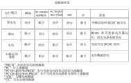
图4示出了关于本发明的实施例的多种运行模式的接触状态。FIG. 4 shows contact states for various operating modes of an embodiment of the present invention.
图5示出了本发明的示例性电路。Figure 5 shows an exemplary circuit of the present invention.
图6示出了本发明的示例性电路。Figure 6 shows an exemplary circuit of the present invention.
具体实施方式Detailed ways
根据要求,公开了本发明的示例性实施例。多个实施例意在作为实施本发明的多种方式的非限制性实例,并且应当理解,本发明可以以可选的形式具体实施。本发明将在下文参考附图做出更充分的说明,附图中相同的附图标记在各图中始终表示相同的元件,并且附图中示出了示例性实施例。附图不一定按比例绘制并且一些特征可能被放大或缩小以显示具体元件的细节,而相关的元件可能已被消除以防止遮掩新颖的方面。此处公开的具体结构性和功能性的细节不应视为限制,而仅仅是作为权利要求的基础,以及作为教导本领域技术人员从多方面使用本发明的代表性基础。例如,虽然在车辆的背景下说明了示例性实施例,但是应当理解,本发明不限于该具体布置。Exemplary embodiments of the present invention are disclosed as required. The embodiments are intended as non-limiting examples of the various ways of implementing the invention, and it is to be understood that the invention may be embodied in alternative forms. The present invention will be described more fully hereinafter with reference to the accompanying drawings, in which like reference numerals refer to like elements throughout the several views, and in which exemplary embodiments are shown. The figures are not necessarily to scale and some features may be exaggerated or minimized to show details of particular elements, while related elements may have been eliminated to prevent obscuring novel aspects. Specific structural and functional details disclosed herein are not to be interpreted as limiting, but merely as a basis for the claims and as a representative basis for teaching one skilled in the art to variously employ the present invention. For example, while the exemplary embodiments are described in the context of a vehicle, it should be understood that the invention is not limited to this particular arrangement.
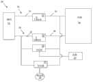
现在参考多幅附图,其中相同的附图标记始终指的是相同的元件,图1示出了具有配置为支持主负载14的可充电能量储存系统(RESS)12的示例性系统10的框图。DC/DC变换器28可以耦接至RESS12来逐步降低它的电压以支持次级负载29。系统10配置为允许DC/DC变换器28在RESS12激励主负载14的同时运行,并且在RESS12被充电的同时运行。Referring now to the several figures, wherein like reference numerals refer to like elements throughout, FIG. 1 shows a block diagram of an
举例来说,但不作为限制,RESS12可以实施为用于电动车辆(EV)、混合动力电动车辆(HEV)或插电式混合动力电动车辆(PHEV)的高压(HV)电池或其他能量储存装置,并且主负载14可以实施为用于车辆的HV负载。例如,HV电池可以包含多电池300V的锂离子电池。在示例性实施例中,主负载14可以包含电源电子变换器,并且可以进一步包括与电气化车辆相关联的其他HV系统和配件。RESS12可以耦接至相反极性的第一电压总线16和第二电压总线18,以便激励主负载14。第一和第二主耦接器20、24可以被设置为允许RESS12与主负载14耦接和解耦。例如,主耦接器20可以配置为将电压总线16的第一部分21耦接至电压总线16的第二部分22。以类似的方式,第二主耦接器24可以配置为将电压总线18的第一部分25耦接至电压总线18的第二部分26。闭合主耦接器20和24允许了RESS12激励负载14。在示例性实施例中,主耦接器可以包含实施为具有可以被激励和去激励的线圈的接触器的开关以提供电连接。By way of example, and not limitation, RESS 12 may be implemented as a high voltage (HV) battery or other energy storage device for an electric vehicle (EV), hybrid electric vehicle (HEV), or plug-in hybrid electric vehicle (PHEV) , and the
在示例性实施例中,DC/DC变换器28可以耦接至电压总线18的第一部分25,并耦接至电压总线16的第二部分22。在该配置中,DC/DC变换器28耦接至电压总线18的“能量”部分,并耦接至电压总线16的“负载”部分。当主耦接器20、24闭合以连接负载14和RESS12时,DC/DC变换器28可以被RESS12激励以支持次级负载29。举例来说,次级负载29可以包含低压系统和设备,如低压车辆电池以及其他低压模块和车辆配件。In an exemplary embodiment, a DC/
图2A示出了包括充电器32的示例性实施例30。充电器32可以配置为将RESS12耦接至用于激励或充电的能量源34。在示例性实施例中,能量源34可以包含从本领域所公知的电力设施提供交流电流的电插座。如图2A中所示,充电器32可以耦接至电压总线18的能量(第一)部分25以及电压总线16的负载(第二)部分22。将充电器与RESS12可控制地耦接和解耦可以提供RESS12被充电而主负载14未被激励的充电模式以及负载14被支持并且充电器32未被激励的运行模式。例如,闭合主耦接器20而断开主耦接器24,这允许了充电器32在不激励主负载14的情况下为RESS12充电。它还允许了DC/DC28在充电过程中运行并支持次级负载29。因此,系统可以防止耗尽用于支持充电过程的多个方面的低压车辆电池。此外,它可以提供将能量补充入低压电池的机会,即便它未用于支持充电过程。FIG. 2A shows an
图2B示出了包括预充电电路38的示例性系统36。在示例性实施例中,预充电电路38可以设置为可控制地激励电压总线的负载部分,并从而激励耦接至电压总线的负载,以避免由来自RESS12经过主耦接器的电流的高涌入造成的损坏和混乱。在示例性实施例中,预充电电路38可以设置为与电压总线16的第一和第二部分21、22耦接,以使第二部分22的充电可以以较低的速率进行,直到它已经被充满电。与负载14一样,DC/DC变换器28也可以受益于预充电功能。FIG. 2B shows an
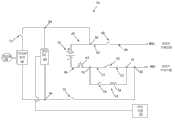
图3示出了用于系统的示例性电路原理图40;然而,应当注意到,对本领域技术人员来说,用于支持本发明的系统的多种其他电路布置也可以存在。出于说明性目的,原理图40将在电动车辆中的部署的背景下进行说明,然而应当理解,本发明的系统和电路可以多方面地应用。高压(HV)电池42可以耦接至第一电压总线44为其提供第一极性,并耦接至第二电压总线46为其提供相反极性。在本实例中,设置高压电池42和电压总线44、46以使电压总线44具有正极性并且电压总线46具有负极性。第一主接触器48可以配置为将第一电压总线44的第一(能量侧)部分47耦接至第一电压总线44的第二(负载侧)部分49。以类似的方式,第二主接触器50可以配置为将第二电压总线46的第一(能量侧)部分51耦接至第二电压总线46的第二(负载侧)部分52。闭合主接触器44、46可以允许电压部分49和52的充电,允许它们支持HV车辆负载(未示出)。FIG. 3 shows an exemplary circuit schematic 40 for the system; however, it should be noted that various other circuit arrangements for supporting the system of the present invention may exist, as will be apparent to those skilled in the art. For illustrative purposes, schematic diagram 40 will be described in the context of deployment in an electric vehicle, however, it should be understood that the systems and circuits of the present invention may be applied in a variety of ways. A high voltage (HV)
可以包括预充电电路以控制并减慢电压总线激励过程,防止来自高压电池42的电荷涌入。例如,预充电电路54可以设置为与主接触器48并联。预充电电路54可以包含与预充电电阻器58串联的预充电接触器或开关56。当预充电接触器56闭合时,主接触器48可以断开并且主接触器50可以闭合,以使来自HV电池42的电流可以流经预充电电路54以便以控制的方式激励电压总线部分49。当预充电功能结束,电压总线部分49、52被充满电时,主接触器48可以闭合并且预充电接触器56可以断开以将电压总线44、46的充电保持在高电位。预充电电路54可以保护主接触器的完整性和使用寿命。主接触器会被来自高压电池的高电荷涌入损坏甚至焊接闭合(welded closed)。通过等待直到电压总线的两侧在闭合主接触器48之前都被充满电,可以保护主接触器48不遭受任何高涌入电流的不利影响。A pre-charge circuit may be included to control and slow down the voltage bus activation process to prevent charge inrush from the
可以包括DC/DC变换器60以支持低压负载62。如本发明前面所述,低压负载62可以包含配置为给多种车辆配件如电动窗、电动锁、娱乐中心、雨刮器、导航设备、内部和外部照明等提供电能的车辆铅酸电池。在示例性实施例中,DC/DC变换器60可以设置为通过节点59和61连接至第一电压总线44的负载侧部分49,并通过节点63和65连接至第二电压总线46的能量侧部分51。节点61的策略性布局允许了DC/DC变换器60利用预充电电路54的功能。DC/DC变换器的电容器一般较大,并且以与输入电位差成正比的速率充电。如果充电过快,直接连接至如典型地应用在EV中的300V电池这样的高压电池的具有零电荷的初始放电状态的电容器会被严重损坏,从而损害DC/DC变换器运行。通过节点61的仔细布局,预充电电路54可以允许DC/DC变换器的电容器以可控制并可耐受的速率被充电,保护DC/DC变换器60的完整性。A DC/
DC/DC变换器60具有两个输入,一个来自电压总线44,另一个来自电压总线46。因为节点61将DC/DC变换器60与电压总线44的负载侧部分49耦接,所以来自电压总线44的输入的充电状态取决于主接触器48和预充电接触器54的断开/闭合状态。当它们都断开时,电压总线44输入不会被激励;如果其中任一个闭合,则电压总线44输入会被激励。然而,因为节点63将DC/DC变换器60与电压总线46的能量侧部分51连接起来,所以电压总线46通常被始终激励。可能的例外可以包括当HV电池42不可操作(如完全放电)时或者当HV电池42已经从电压总线46解耦时。例如,可以设置维修断路开关(service disconnect)(SD)64以允许将HV电池42手动解耦以将其从车辆负载移除。例如,HV电池42自身或主接触器48、50中的一个可能会出现问题。SD64可以配置为将HV电池42解耦,以允许电池42自身、有缺陷的电路元件或车辆的部件的维修或装配以保护操作者的安全并保护其余的电路元件的方式执行。在示例性实施例中,SD64包含可以手动控制的接触器开关。DC/
充电器装置66可以设置为允许HV电池42由能量源68充电。在示例性布置中,充电器装置66可以设置为与DC/DC变换器60并联,DC/DC变换器60耦接至一个电压总线的负载侧部分以及另一个电压总线的能量侧部分。在图3的示例性实施例中,DC/DC变换器60和充电器装置66可以通过节点61连接至电压总线44的负载侧部分49,并通过节点63连接至电压总线46的能量侧部分51。在示例性实施例中,可以设置可选的辅助接触器(AXC)70以将充电器装置66与节点61以及电压总线44的负载侧部分49可控制地耦接和解耦。如图3中所示,AXC70的布局可以允许其将DC/DC变换器60以及充电器装置66解耦。当以这种方式设置时,AXC70可以断开以允许在没有来自总线44的激励输入的情况下维修DC/DC60和/或充电器装置66,断开主接触器48会存在问题,例如主接触器48被焊接关闭。A
通过另一实例(未示出),AXC70可以置于DC/DC60与充电器装置66之间,例如,节点59与充电器装置66之间。在这种布置中,AXC70可以用于将充电器装置66从电压总线44解耦,而不用将DC/DC变换器60从电压总线44解耦。相应地,电压总线44可以允许DC/DC60在车辆驱动的过程中为低压负载62提供能量,而不用激励充电器装置66。这种类型的配置可以在具有高到足以不利地影响燃油经济性的寄生负载的充电器的电路中提供一种优势。如果在充电器没有充分保护的情况下,到充电器的AC输入被激励,则也可以证明其有益。By way of another example (not shown),
再次参考图3中所示的示例性布置,示例性电路40还可以包括可选的充电器接触器(CC)72,其配置为将充电器装置66从另一电压总线46解耦。因此,示例性系统可以包括将每个电压总线输入连接至充电器的可控制的接触器。在示例性实施例中,CC72可以配置为将充电器装置66从电压总线46解耦,而不将DC/DC变换器60从电压总线46解耦。这种配置允许了DC/DC变换器60在车辆驱动模式过程中未使用充电器时运行。例如,在车辆驱动过程中,主接触器48和50可以闭合,AXC70可以闭合并且充电器接触器72可以断开以将充电器66从电压总线46解耦。在这种配置中,DC/DC变换器60耦接至HV电池42以允许其支持车辆运行,但充电器66未被激励。然而,在HV电池42被充电时,主接触器48以及接触器70和72可以闭合而主接触器50断开,允许充电器66为HV电池42充电,并允许DC/DC变换器60在充电过程中支持相关的低压负载。在充电过程中将主接触器50保持在断开状态可以防止HV负载在充电过程中被激励。Referring again to the exemplary arrangement shown in FIG. 3 , the
因此,本发明的系统可以允许在车辆运行过程中以及车辆电池充电的过程中充电器装置的耦接/解耦、允许DC/DC变换器运行,并允许DC/DC变换器得益于预充电电路。通过控制多个接触器,多种操作模式可以得到支持,如图4所示。在示例性实施例中,多个接触器的控制可以由例如与HV电池相关联的电池能量控制模块的相关的一个或多个控制器或者由例如车辆系统控制器、电子控制单元等较高的车辆控制系统或子系统来执行。应当预料到,集中控制系统可以配置为控制主接触器、辅助和充电器接触器,以及预充电电路。Thus, the system of the present invention may allow the coupling/decoupling of the charger device during vehicle operation and during charging of the vehicle battery, allow the DC/DC converter to operate, and allow the DC/DC converter to benefit from pre-charging circuit. Multiple operating modes can be supported by controlling multiple contactors, as shown in Figure 4. In an exemplary embodiment, control of the plurality of contactors may be performed by an associated controller or controllers, such as a battery energy control module associated with the HV battery, or by a higher level, such as a vehicle system controller, electronic control unit, etc. Vehicle control system or subsystem to perform. It is contemplated that the centralized control system may be configured to control the main contactors, auxiliary and charger contactors, and the pre-charging circuit.
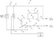
虽然图3示出了示例性布置,但是也可以应用其他布置来提供具有预充电功能的电路,其中充电器装置和/或DC/DC变换器耦接至一个极性的高压总线的能量侧并耦接至相反极性的高压总线的负载侧。例如,图5示出了实例74,其中预充电电路54配置为越过负主接触器,即主接触器50,而不是配置为如图3中所示的越过正主接触器。预充电电路54可以通过能量侧部分51上的节点76以及负载侧部分52上的节点78连接至电压总线46。在实例74中,充电器装置66通过节点80在主接触器48的能量侧47耦接至电压总线44,并通过节点82在主接触器50的负载侧52耦接至电压总线46。类似地,DC/DC变换器60通过节点80和84在主接触器48的能量侧47耦接至正电压总线44,并通过节点82和86在主接触器50的负载侧52耦接至电压总线46。在该示例性布置中,AXC70配置为将DC/DC变换器60和充电器装置66与HV-总线,即电压总线46耦接/解耦。通过非限制性实例,预充电电路54和AXC70可以耦接至相同的电压总线。如图5中所示,充电器接触器可以配置为将充电器装置与正电压总线耦接,如通过配置为将充电器装置66耦接至电压总线44的充电器接触器72所示出的。因此,充电器装置66可以与每个高压总线44、46可控制地耦接和解耦,并且DC/DC变换器60可以在驱动和充电模式以及需要DC/DC变换器运行以支持低压电池和/或低压负载的非充电、非驱动模式过程中运行。Although FIG. 3 shows an exemplary arrangement, other arrangements may be applied to provide a circuit with a pre-charge function, wherein a charger device and/or a DC/DC converter is coupled to the energy side of a high voltage bus of one polarity and Couple to the load side of the high voltage bus of opposite polarity. For example, FIG. 5 shows an example 74 in which the
如本领域技术人员应当理解的,还可以在本发明的实施中使用另外的电路排布,其中预充电电路、充电器接触器、辅助接触器和/或维修断路开关可变化地放置。例如,图3和5示出了耦接至相同电压总线的预充电电路和辅助接触器,其中充电器接触器耦接至相反的电压总线。这种布置可以改变但仍然提供本发明的功能。举例来说,图6示出了示例性电路90,其中预充电电路54耦接至电压总线44,而AXC70耦接至相反的电压总线46。在实例90中,DC/DC变换器通过节点61、92耦接至电压总线44的负载侧部分49,并通过节点63和94耦接至电压总线46的能量侧部分51。AXC70可以可控制地耦接DC/DC变换器60和充电器装置66与负电压总线46。充电器接触器72可以可控制地耦接充电器装置66与正电压总线44。保持了DC/DC变换器60的预充电以及充电器装置66和DC/DC变换器60的同时运行。对本领域技术人员来说,可以出现另外的电路排布。As will be appreciated by those skilled in the art, alternative circuit arrangements may also be used in the practice of the present invention in which the pre-charge circuit, charger contactor, auxiliary contactor and/or service disconnect switch are variably placed. For example, FIGS. 3 and 5 show a pre-charge circuit and an auxiliary contactor coupled to the same voltage bus, where the charger contactor is coupled to an opposite voltage bus. This arrangement can be varied and still provide the functionality of the present invention. For example, FIG. 6 shows an
应当注意到,在不影响电路功能的前提下,SD可以设置在任一极性的电压总线上。SD优选置于RESS与主接触器之间,以便其可以用于将主接触器和电压总线从RESS解耦。例如,接触器会被损坏并需要修理。损坏的接触器,如焊接关闭的接触器与电池之间的SD允许接触器(及相关联的电压总线的负载侧部分)从电池解耦以停止它的激励,以便其可以以安全的方式被替换。例如,参考图5,在又一示例性实施例中,SD64可以置于RESS42与节点80之间的电压总线44上。It should be noted that under the premise of not affecting the circuit function, SD can be set on the voltage bus of any polarity. The SD is preferably placed between the RESS and the main contactor so that it can be used to decouple the main contactor and the voltage bus from the RESS. For example, contactors can become damaged and require repair. A damaged contactor, such as a soldered-off SD between the contactor and the battery allows the contactor (and the associated load-side portion of the voltage bus) to be decoupled from the battery to stop its energization so that it can be removed in a safe manner. replace. For example, referring to FIG. 5 , in yet another exemplary embodiment,
本发明的系统提供优于DC/DC变换器耦接至HV+主接触器和HV-主接触器的负载侧的现有技术系统的优势。在那种类型的排布中,DC/DC变换器通常在车辆驱动过程中两个主接触器都闭合时运行,而在电池充电过程中两个主接触器都断开时不运行。因此,充电器一般不得不包括其自己的辅助变换器以支持充电过程。本发明提供了一种系统,其中车辆DC/DC变换器可以在高压电池充电过程中运行以支持车辆低压电池和负载。例如,在充电过程中,充电器可以消耗来自车辆低压电池的电能用于控制电路。此外,可以通过来自低压电池的电能在充电过程中支持其他模块,如电池能量控制模块。在某些情况下,低压负载可以因预处理系统增加,其中预处理系统可以在充电过程中被激活以通过打开另外耗用低压电池的鼓风机电动机等等为驾驶员预热车辆。没有DC/DC变换器的运行,会存在低压电池可能不能提供充分支持的风险。The system of the invention offers advantages over prior art systems where the DC/DC converter is coupled to the load side of the HV+ main contactor and the HV- main contactor. In that type of arrangement, the DC/DC converter typically operates when both main contactors are closed during vehicle drive and does not operate when both main contactors are open during battery charging. Therefore, the charger generally has to include its own auxiliary converter to support the charging process. The present invention provides a system in which a vehicle DC/DC converter can operate to support a vehicle low voltage battery and load during high voltage battery charging. For example, during charging, the charger may consume power from the vehicle's low-voltage battery for control circuitry. In addition, other modules, such as the battery energy control module, can be supported during the charging process by power from the low-voltage battery. In some cases the low voltage load can be increased by a pre-conditioning system which can be activated during charging to warm up the vehicle for the driver by turning on the blower motor which otherwise drains the low voltage battery, etc. In operation without a DC/DC converter, there is a risk that the low voltage battery may not be able to provide adequate support.
随着充电过程可以变得更复杂,未来可以预期额外的负载。举例来说,但不作为限制,可以建立包含受控制的电力网交互以实现更有效的资源分配的公共充电站。例如,某些设施可以延迟停放较长的一段时间的车辆,如那些停放在机场充电站的车辆的充电过程。因此,为激活某些模块以起动延迟的充电过程而设计的控制通信需要低压电能。出于同样原因,消费者可能将车辆停放在充电插座处,并希望延迟充电过程以利用非高峰时段所提供的较低的电力价格。允许DC/DC变换器在充电和驱动模式中都支持低压电池允许了电池变得更小,即便负载可以变得更大。Additional loads can be expected in the future as the charging process can become more complex. By way of example, and not limitation, public charging stations could be established that include controlled power grid interaction for more efficient resource allocation. For example, some facilities may delay the charging process for vehicles parked for an extended period of time, such as those parked at airport charging stations. Therefore, low voltage power is required for control communications designed to activate certain modules to initiate the delayed charging process. For the same reason, consumers may park their vehicles at a charging outlet and wish to delay the charging process to take advantage of lower electricity prices available during off-peak hours. Allowing the DC/DC converter to support the low voltage battery in both charge and drive modes allows the battery to be smaller even as the load can be made larger.
虽然已经描述了多种示例性电路布置以便教导本发明的各个方面,但是本发明并不限于这里所说明的实例,应当理解,对本领域技术人员来说,也可以出现权利要求保护范围内另外的示例性电路。While various exemplary circuit arrangements have been described in order to teach the various aspects of the present invention, the present invention is not limited to the examples illustrated herein, and it should be understood that other alternatives within the scope of the claims may occur to those skilled in the art. Exemplary circuit.
Claims (8)
Applications Claiming Priority (2)
| Application Number | Priority Date | Filing Date | Title |
|---|---|---|---|
| US13/555,499 | 2012-07-23 | ||
| US13/555,499US9266433B2 (en) | 2012-07-23 | 2012-07-23 | Low cost charger circuit with precharge |
Publications (2)
| Publication Number | Publication Date |
|---|---|
| CN103568861Atrue CN103568861A (en) | 2014-02-12 |
| CN103568861B CN103568861B (en) | 2017-03-01 |
Family
ID=49880009
Family Applications (1)
| Application Number | Title | Priority Date | Filing Date |
|---|---|---|---|
| CN201310306677.3AActiveCN103568861B (en) | 2012-07-23 | 2013-07-19 | There is the inexpensive charger circuit of pre-charging functions |
Country Status (3)
| Country | Link |
|---|---|
| US (1) | US9266433B2 (en) |
| CN (1) | CN103568861B (en) |
| DE (1) | DE102013107644A1 (en) |
Cited By (3)
| Publication number | Priority date | Publication date | Assignee | Title |
|---|---|---|---|---|
| CN104890518A (en)* | 2014-03-07 | 2015-09-09 | 福特全球技术公司 | High voltage cutoff for electrified vehicles |
| CN105098863A (en)* | 2014-05-22 | 2015-11-25 | 上海汽车集团股份有限公司 | Battery device, driving device, driving system and control method for driving system |
| CN105453376A (en)* | 2013-08-07 | 2016-03-30 | 罗伯特·博世有限公司 | Precharging unit for a battery interruption unit |
Families Citing this family (26)
| Publication number | Priority date | Publication date | Assignee | Title |
|---|---|---|---|---|
| US9266433B2 (en)* | 2012-07-23 | 2016-02-23 | Ford Global Technologies, Llc | Low cost charger circuit with precharge |
| US9630503B2 (en)* | 2014-02-06 | 2017-04-25 | Ford Global Technologies, Llc | Energizing an automotive vehicle high voltage bus using a single main contactor |
| FR3017754B1 (en)* | 2014-02-14 | 2018-04-27 | Commissariat A L'energie Atomique Et Aux Energies Alternatives | CONTINUOUS VOLTAGE SUPPLY SYSTEM CONFIGURED TO PRECHARGE A FILTER CAPACITOR BEFORE FEEDING A LOAD |
| US9914416B2 (en) | 2014-03-31 | 2018-03-13 | Ford Global Technologies, Llc | System and method for closing a contactor on early wake to improve vehicle start time |
| CN106165247B (en)* | 2014-04-08 | 2017-11-07 | 日产自动车株式会社 | Contactless power supply system and noncontact current-collecting device |
| KR101736475B1 (en)* | 2015-02-04 | 2017-05-16 | 한화테크윈 주식회사 | Electric vehicle |
| CN105984353B (en)* | 2015-02-09 | 2018-12-25 | 台达电子工业股份有限公司 | Battery power supply integration device and oil-electricity hybrid vehicle power supply system with same |
| US9923470B2 (en) | 2015-09-18 | 2018-03-20 | Lear Corporation | High voltage pre-charge system |
| KR102145524B1 (en)* | 2016-06-22 | 2020-08-18 | 주식회사 엘지화학 | Driver circuit for an electric vehicle and control method for the same |
| DE102016213070B4 (en)* | 2016-07-18 | 2017-05-11 | Continental Automotive Gmbh | Vehicle electrical system and procedure |
| US10913369B2 (en)* | 2017-02-16 | 2021-02-09 | Ford Global Technologies, Llc | Charging energy recapture assembly and method |
| US10027223B1 (en) | 2017-06-12 | 2018-07-17 | Linear Technology Holding Llc | Soft-charging of switched capacitors in power converter circuits |
| US10181804B1 (en) | 2017-08-11 | 2019-01-15 | Linear Technology Holding Llc | Soft-start circuit for switched resonant power converters |
| US10744891B2 (en)* | 2017-12-11 | 2020-08-18 | Fca Us Llc | Voltage control for alternator mode in electrified vehicles |
| JP6919605B2 (en)* | 2018-03-13 | 2021-08-18 | 株式会社デンソー | Heater device |
| CN108528242B (en)* | 2018-03-29 | 2020-04-21 | 吉利汽车研究院(宁波)有限公司 | Medium and low voltage power on and off control method, device and electronic equipment |
| JP7073865B2 (en)* | 2018-04-09 | 2022-05-24 | トヨタ自動車株式会社 | Redundant power supply system |
| US10696181B2 (en) | 2018-08-06 | 2020-06-30 | Ford Global Technologies, Llc | Systems and methods for controlling charging of electrified vehicle auxiliary batteries |
| US10654372B2 (en)* | 2018-10-18 | 2020-05-19 | Textron Innovations Inc. | Controlling power to a utility vehicle |
| CN109818393B (en)* | 2019-01-23 | 2020-05-19 | 宁德时代新能源科技股份有限公司 | A kind of precharge circuit and precharge method of high voltage battery pack |
| DE102019111785A1 (en)* | 2019-05-07 | 2020-11-12 | Dr. Ing. H.C. F. Porsche Aktiengesellschaft | Method and device for charging an electric vehicle with a charging cable |
| DE102020202349B4 (en) | 2020-02-24 | 2022-01-13 | Volkswagen Aktiengesellschaft | Method of operating a battery powered electric vehicle |
| EP4140800A1 (en)* | 2021-08-30 | 2023-03-01 | ABB E-mobility B.V. | Electric vehicle charging arrangement with pre-arging and method for charging an electric vehicle |
| CN115771415B (en)* | 2021-09-07 | 2025-06-20 | 通用汽车环球科技运作有限责任公司 | Controlling DC-DC converter for DC charging |
| NL2031706B1 (en)* | 2022-04-26 | 2023-11-10 | Total Safety Solutions B V | A high-voltage direct current circuit for an electric vehicle with a secondary relay |
| SE545814C2 (en)* | 2022-06-30 | 2024-02-06 | Scania Cv Ab | Method of Managing the Supply of Electrical Energy in a Vehicle, Control Arrangement, and Vehicle |
Citations (4)
| Publication number | Priority date | Publication date | Assignee | Title |
|---|---|---|---|---|
| JP2000287302A (en)* | 1999-03-31 | 2000-10-13 | Toshiba Battery Co Ltd | Vehicle energy management device and vehicle |
| JP4581302B2 (en)* | 2001-07-05 | 2010-11-17 | 日産自動車株式会社 | Control device for hybrid vehicle |
| WO2011061809A1 (en)* | 2009-11-17 | 2011-05-26 | トヨタ自動車株式会社 | Vehicle and method for controlling vehicle |
| WO2011152164A1 (en)* | 2010-05-31 | 2011-12-08 | スズキ株式会社 | Vehicle charger mounting structure |
Family Cites Families (7)
| Publication number | Priority date | Publication date | Assignee | Title |
|---|---|---|---|---|
| JP3330049B2 (en) | 1997-03-07 | 2002-09-30 | 本田技研工業株式会社 | Electric vehicle control device |
| JP5339983B2 (en)* | 2008-05-19 | 2013-11-13 | 富士重工業株式会社 | Electric vehicle control device |
| JP5302749B2 (en)* | 2009-04-20 | 2013-10-02 | 富士重工業株式会社 | Electric vehicle control device |
| JP4835733B2 (en)* | 2009-08-27 | 2011-12-14 | トヨタ自動車株式会社 | VEHICLE CHARGE CONTROL DEVICE AND ELECTRIC VEHICLE HAVING THE SAME |
| JP5293841B2 (en)* | 2010-02-09 | 2013-09-18 | トヨタ自動車株式会社 | Electric vehicle power supply system and control method thereof |
| JP5556354B2 (en)* | 2010-05-18 | 2014-07-23 | スズキ株式会社 | Control device for power supply circuit |
| US9266433B2 (en)* | 2012-07-23 | 2016-02-23 | Ford Global Technologies, Llc | Low cost charger circuit with precharge |
- 2012
- 2012-07-23USUS13/555,499patent/US9266433B2/enactiveActive
- 2013
- 2013-07-18DEDE102013107644.0Apatent/DE102013107644A1/ennot_activeWithdrawn
- 2013-07-19CNCN201310306677.3Apatent/CN103568861B/enactiveActive
Patent Citations (5)
| Publication number | Priority date | Publication date | Assignee | Title |
|---|---|---|---|---|
| JP2000287302A (en)* | 1999-03-31 | 2000-10-13 | Toshiba Battery Co Ltd | Vehicle energy management device and vehicle |
| JP4581302B2 (en)* | 2001-07-05 | 2010-11-17 | 日産自動車株式会社 | Control device for hybrid vehicle |
| WO2011061809A1 (en)* | 2009-11-17 | 2011-05-26 | トヨタ自動車株式会社 | Vehicle and method for controlling vehicle |
| WO2011152164A1 (en)* | 2010-05-31 | 2011-12-08 | スズキ株式会社 | Vehicle charger mounting structure |
| JP2011250660A (en)* | 2010-05-31 | 2011-12-08 | Suzuki Motor Corp | Structure for mounting charger of on-board system circuit |
Cited By (6)
| Publication number | Priority date | Publication date | Assignee | Title |
|---|---|---|---|---|
| CN105453376A (en)* | 2013-08-07 | 2016-03-30 | 罗伯特·博世有限公司 | Precharging unit for a battery interruption unit |
| CN104890518A (en)* | 2014-03-07 | 2015-09-09 | 福特全球技术公司 | High voltage cutoff for electrified vehicles |
| US10230231B2 (en) | 2014-03-07 | 2019-03-12 | Ford Global Technologies, Llc | High voltage cutoff for electrified vehicles |
| CN104890518B (en)* | 2014-03-07 | 2019-07-19 | 福特全球技术公司 | High voltage for electrified vehicle is cut off |
| CN105098863A (en)* | 2014-05-22 | 2015-11-25 | 上海汽车集团股份有限公司 | Battery device, driving device, driving system and control method for driving system |
| CN105098863B (en)* | 2014-05-22 | 2018-06-26 | 上海汽车集团股份有限公司 | Cell apparatus, driving device, the control method of drive system and drive system |
Also Published As
| Publication number | Publication date |
|---|---|
| US9266433B2 (en) | 2016-02-23 |
| CN103568861B (en) | 2017-03-01 |
| US20140021916A1 (en) | 2014-01-23 |
| DE102013107644A1 (en) | 2014-01-23 |
Similar Documents
| Publication | Publication Date | Title |
|---|---|---|
| CN103568861B (en) | There is the inexpensive charger circuit of pre-charging functions | |
| CN109808522B (en) | Composite bidirectional integrated charger for vehicles | |
| KR102419697B1 (en) | A storage battery charging device for a vehicle, a method of operating an onboard storage battery charging device, a high voltage vehicle electrical system, and use of the storage battery charging device | |
| CN109070761B (en) | Switchable reservoir system for a vehicle | |
| US9365115B2 (en) | System and method for vehicle power management | |
| CN102089177B (en) | Electric vehicle | |
| CN103166278A (en) | Recharge systems and methods | |
| US20140343776A1 (en) | Power supply system for vehicle | |
| US20200055412A1 (en) | Circuit and charging method for an electrical energy storage system | |
| EP3800083B1 (en) | Power-supply and recharge groups of an electric vehicle and methods thereof | |
| JP2008206300A (en) | Electric vehicle, vehicle charging device, and vehicle charging system | |
| CN104253464A (en) | System for mutual charging of electric vehicles and charging connector | |
| CN103119826A (en) | Charging system and charging control method for electric vehicle | |
| CN112550072B (en) | Energy system for an electrically driven vehicle | |
| CN113043869A (en) | Battery system for vehicle and method for operating the same | |
| CN104734274A (en) | Vehicle Battery Charging Apparatus And Method Using The Same | |
| CN213007972U (en) | Charging circuit and vehicle | |
| KR20140079626A (en) | System and method for charging battery of vehicle | |
| IT201900001099A1 (en) | GROUP AND METHOD OF CHARGING AND POWER SUPPLY FOR AN ELECTRIC VEHICLE, AND ELECTRIC VEHICLE INCLUDING THE CHARGING AND POWER UNIT | |
| CN114365375A (en) | Multi-voltage storage system for at least partially electrically driven vehicles | |
| KR20120069859A (en) | Mobile charge system | |
| JP2021118629A (en) | Vehicle battery control device | |
| JP5545607B2 (en) | Charger | |
| JP2018098954A (en) | Controller for electric vehicle | |
| CN116620035A (en) | Vehicle and power domain integrated controller |
Legal Events
| Date | Code | Title | Description |
|---|---|---|---|
| C06 | Publication | ||
| PB01 | Publication | ||
| EXSB | Decision made by sipo to initiate substantive examination | ||
| SE01 | Entry into force of request for substantive examination | ||
| GR01 | Patent grant | ||
| GR01 | Patent grant |