CN103568206A - Pre-plasticizing shaft supporting and connecting device - Google Patents
Pre-plasticizing shaft supporting and connecting deviceDownload PDFInfo
- Publication number
- CN103568206A CN103568206ACN201310504707.1ACN201310504707ACN103568206ACN 103568206 ACN103568206 ACN 103568206ACN 201310504707 ACN201310504707 ACN 201310504707ACN 103568206 ACN103568206 ACN 103568206A
- Authority
- CN
- China
- Prior art keywords
- bearing
- deep groove
- shaft
- groove ball
- bearing seat
- Prior art date
- Legal status (The legal status is an assumption and is not a legal conclusion. Google has not performed a legal analysis and makes no representation as to the accuracy of the status listed.)
- Granted
Links
- 238000007789sealingMethods0.000claimsabstractdescription22
- 125000006850spacer groupChemical group0.000claimsdescription29
- 230000006835compressionEffects0.000claimsdescription12
- 238000007906compressionMethods0.000claimsdescription12
- 210000004907glandAnatomy0.000claimsdescription10
- 238000000465mouldingMethods0.000abstractdescription20
- 238000001746injection mouldingMethods0.000abstractdescription13
- 238000002347injectionMethods0.000abstractdescription4
- 239000007924injectionSubstances0.000abstractdescription4
- 230000007774longtermEffects0.000abstractdescription4
- 238000000034methodMethods0.000description4
- 238000010586diagramMethods0.000description2
- 239000000428dustSubstances0.000description2
- 239000010687lubricating oilSubstances0.000description2
- 230000009286beneficial effectEffects0.000description1
- 230000000694effectsEffects0.000description1
- 238000005516engineering processMethods0.000description1
- 238000009434installationMethods0.000description1
- 239000000463materialSubstances0.000description1
- 238000012986modificationMethods0.000description1
- 230000004048modificationEffects0.000description1
- 238000003825pressingMethods0.000description1
- 239000000243solutionSubstances0.000description1
- 239000013589supplementSubstances0.000description1
Images


Classifications
- B—PERFORMING OPERATIONS; TRANSPORTING
- B29—WORKING OF PLASTICS; WORKING OF SUBSTANCES IN A PLASTIC STATE IN GENERAL
- B29C—SHAPING OR JOINING OF PLASTICS; SHAPING OF MATERIAL IN A PLASTIC STATE, NOT OTHERWISE PROVIDED FOR; AFTER-TREATMENT OF THE SHAPED PRODUCTS, e.g. REPAIRING
- B29C45/00—Injection moulding, i.e. forcing the required volume of moulding material through a nozzle into a closed mould; Apparatus therefor
- B29C45/17—Component parts, details or accessories; Auxiliary operations
- B29C45/1775—Connecting parts, e.g. injection screws, ejectors, to drive means
- F—MECHANICAL ENGINEERING; LIGHTING; HEATING; WEAPONS; BLASTING
- F16—ENGINEERING ELEMENTS AND UNITS; GENERAL MEASURES FOR PRODUCING AND MAINTAINING EFFECTIVE FUNCTIONING OF MACHINES OR INSTALLATIONS; THERMAL INSULATION IN GENERAL
- F16C—SHAFTS; FLEXIBLE SHAFTS; ELEMENTS OR CRANKSHAFT MECHANISMS; ROTARY BODIES OTHER THAN GEARING ELEMENTS; BEARINGS
- F16C33/00—Parts of bearings; Special methods for making bearings or parts thereof
- F16C33/72—Sealings
- F16C33/76—Sealings of ball or roller bearings
- F16C33/78—Sealings of ball or roller bearings with a diaphragm, disc, or ring, with or without resilient members
- F16C33/7803—Sealings of ball or roller bearings with a diaphragm, disc, or ring, with or without resilient members suited for particular types of rolling bearings
- F16C33/7806—Sealings of ball or roller bearings with a diaphragm, disc, or ring, with or without resilient members suited for particular types of rolling bearings for spherical roller bearings
- F—MECHANICAL ENGINEERING; LIGHTING; HEATING; WEAPONS; BLASTING
- F16—ENGINEERING ELEMENTS AND UNITS; GENERAL MEASURES FOR PRODUCING AND MAINTAINING EFFECTIVE FUNCTIONING OF MACHINES OR INSTALLATIONS; THERMAL INSULATION IN GENERAL
- F16C—SHAFTS; FLEXIBLE SHAFTS; ELEMENTS OR CRANKSHAFT MECHANISMS; ROTARY BODIES OTHER THAN GEARING ELEMENTS; BEARINGS
- F16C35/00—Rigid support of bearing units; Housings, e.g. caps, covers
- F16C35/08—Rigid support of bearing units; Housings, e.g. caps, covers for spindles
- F16C35/12—Rigid support of bearing units; Housings, e.g. caps, covers for spindles with ball or roller bearings
Landscapes
- Engineering & Computer Science (AREA)
- General Engineering & Computer Science (AREA)
- Mechanical Engineering (AREA)
- Manufacturing & Machinery (AREA)
- Mounting Of Bearings Or Others (AREA)
Abstract
Translated fromChinese
Description
Translated fromChinese技术领域technical field
本发明属于注塑技术领域,涉及一种注塑机,尤其是涉及一种预塑轴支撑连接装置。The invention belongs to the technical field of injection molding, and relates to an injection molding machine, in particular to a premolded shaft support connection device.
背景技术Background technique
塑螺杆在工作过程的不同阶段,具有多种运动方式,并且需要施加多种作用力。在预塑阶段螺杆转动,同时慢速后退,需要给螺杆施加扭矩,以及向后的拉力;在注射阶段,螺杆不转动,但是向前推进,需要给螺杆施加向前的巨大推力;在保压阶段,螺杆不转动,也不进退,但保持向塑料熔体施压,需要给螺杆施加向前的巨大推力。注塑机对螺杆的运动速度、力的大小都有严格要求,其中向前的推力数值巨大,高品质注塑机也期望注塑零部件有长久牢固稳定的性能,而这些各种运动和各种力均通过预塑轴传递而来。现有技术中的预塑轴的支撑连接不牢固、不可靠、且使用寿命短,所以,为实现复杂的运动并传递多方向的力,必须解决预塑轴的支撑连接设计这个棘手问题。The plastic screw has a variety of movement modes at different stages of the working process, and needs to apply a variety of forces. In the pre-plastic stage, the screw rotates and retreats at a slow speed, and torque and backward pulling force need to be applied to the screw; in the injection stage, the screw does not rotate, but advances forward, and a huge forward thrust needs to be applied to the screw; In the first stage, the screw does not rotate, nor advances and retreats, but to keep applying pressure to the plastic melt, it is necessary to apply a huge forward thrust to the screw. Injection molding machines have strict requirements on the movement speed and force of the screw, among which the forward thrust value is huge. High-quality injection molding machines also expect long-term firm and stable performance of injection molding parts, and these various movements and forces are Passed through the pre-molded shaft. The support connection of the pre-plastic shaft in the prior art is not firm, unreliable, and has a short service life. Therefore, in order to realize complex movements and transmit multi-directional forces, the thorny problem of the design of the support connection of the pre-plastic shaft must be solved.
发明内容Contents of the invention
本发明的目的是针对上述问题,提供一种预塑轴支撑连接装置;解决了现有技术所存在的结构不牢固、不可靠,影使用寿命短等技术问题。The object of the present invention is to solve the above problems and provide a pre-molded shaft support connection device, which solves the technical problems of weak structure, unreliability and short service life of the shadow in the prior art.
为达到上述目的,本发明采用了下列技术方案:一种预塑轴支撑连接装置,包括预塑台,固定在预塑台上的轴承座,穿设在轴承座内的预塑轴,所述的轴承座的内腔两端设置有前深沟球轴承和后深沟球轴承,在前深沟球轴承和后深沟球轴承之间设置有推力轴承,预塑轴穿设在前深沟球轴承、后深沟球轴承和推力轴承中,轴承座两端设置有前轴承盖和后轴承盖,预塑轴与前轴承盖和后轴承盖的连接处设置有前密封圈和后密封圈,所述的前密封圈和后密封圈分别嵌入在前轴承盖和后轴承盖中;In order to achieve the above object, the present invention adopts the following technical solutions: a pre-plastic shaft supporting connection device, including a pre-plastic table, a bearing seat fixed on the pre-plastic table, a pre-plastic shaft pierced in the bearing seat, the The two ends of the inner cavity of the bearing seat are provided with front deep groove ball bearings and rear deep groove ball bearings, and thrust bearings are arranged between the front deep groove ball bearings and rear deep groove ball bearings, and the pre-plastic shaft is installed in the front deep groove For ball bearings, rear deep groove ball bearings and thrust bearings, front bearing caps and rear bearing caps are provided at both ends of the bearing housing, and front sealing rings and rear sealing rings are provided at the connection between the pre-molded shaft and the front bearing caps and rear bearing caps. , the front sealing ring and the rear sealing ring are respectively embedded in the front bearing cover and the rear bearing cover;
所述的预塑台中心具有预塑台前侧主孔和预塑台后侧主孔,预塑台前侧主孔和预塑台后侧主孔的连接处向内凹陷形成圆环状的空腔;The center of the pre-plastic table has a main hole on the front side of the pre-plastic table and a main hole on the rear side of the pre-plastic table. cavity;
所述的轴承座内部具有第一隔环,所述的第一隔环将轴承座内部隔成轴承座前侧主孔和轴承座后侧主孔,轴承座的一端还设置有沿轴承座径向向外部突出的凸缘;There is a first spacer ring inside the bearing seat, and the first spacer ring divides the interior of the bearing seat into the main hole on the front side of the bearing seat and the main hole on the rear side of the bearing seat. outwardly projecting flanges;
所述的预塑轴前端具有预塑轴压盖,所述的预塑轴压盖固定连接螺杆,预塑轴内部具有中心孔,外壁的中部具有沿预塑轴径向向外突出的呈圆环状的第二隔环,预塑轴后端具有外螺纹,压紧螺母旋入外螺纹中与预塑轴固定连接;The front end of the pre-molded shaft has a pre-molded shaft gland, the pre-molded shaft gland is fixedly connected to the screw rod, the inside of the pre-molded shaft has a central hole, and the middle part of the outer wall has a circular shape that protrudes radially outward along the pre-molded shaft. The ring-shaped second spacer, the rear end of the pre-molded shaft has an external thread, and the compression nut is screwed into the external thread to be fixedly connected with the pre-molded shaft;
所述的后深沟球轴承位于第一隔环与后轴承盖之间,所述的前深沟球轴承位于第二隔环与前轴承盖之间,所述推力轴承位于第一隔环和第二隔环之间。The rear deep groove ball bearing is located between the first spacer ring and the rear bearing cap, the front deep groove ball bearing is located between the second spacer ring and the front bearing cap, and the thrust bearing is located between the first spacer ring and the rear bearing cap. between the second ring.
在上述的预塑轴支撑连接装置中,所述的轴承座与前轴承盖之间还设置有前垫片,轴承座与后轴承盖之间还设置有后垫片。In the above-mentioned pre-plastic shaft supporting and connecting device, a front gasket is further arranged between the bearing seat and the front bearing cap, and a rear gasket is also arranged between the bearing seat and the rear bearing cap.
在上述的预塑轴支撑连接装置中,所述的后密封圈与预塑轴之间设置有圆环,所述的预塑轴后端用压紧螺母旋入外螺纹中压紧后轴承盖,所述的圆环一端顶住后深沟球轴承,另一端顶住压紧螺母。In the above-mentioned pre-molded shaft supporting connection device, a circular ring is arranged between the rear sealing ring and the pre-molded shaft, and the rear end of the pre-molded shaft is screwed into the external thread with a compression nut to compress the rear bearing cap , one end of the ring withstands the rear deep groove ball bearing, and the other end withstands the compression nut.
在上述的预塑轴支撑连接装置中,所述的预塑轴前端的外壁上设置有预塑带轮。In the above-mentioned supporting connection device for the pre-molded shaft, a pre-molded pulley is arranged on the outer wall of the front end of the pre-molded shaft.
与现有的技术相比,本发明的有益效果是:可以承受轴向向后的巨大推力、轴向向前的较小拉力、扭矩、径向力等作用力,而且预塑轴可以灵活转动,相对运动摩擦部位封装在密闭空间内,避免润滑油外泄和灰尘进入。本发明的装置能够保障注塑机实现预塑和注射功能,并且使注塑机具有长久牢固稳定的性能。 Compared with the existing technology, the beneficial effect of the present invention is that it can withstand the huge axial backward thrust, the axial forward small pulling force, torque, radial force and other forces, and the pre-plastic shaft can rotate flexibly , The relative motion friction parts are sealed in a closed space to avoid the leakage of lubricating oil and the entry of dust. The device of the invention can ensure that the injection molding machine realizes the functions of premolding and injection, and enables the injection molding machine to have long-term firm and stable performance. the
附图说明Description of drawings
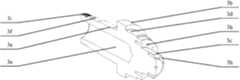
图1是本发明提供的外形示意图;Fig. 1 is the outline schematic diagram provided by the present invention;
图2是图1的垂直剖切示意图;Fig. 2 is the vertical section schematic diagram of Fig. 1;
图3是本发明提供的预塑台的结构示意图;Fig. 3 is the structural representation of the pre-plastic platform provided by the present invention;
图4是本发明提供的轴承座的结构示意图;Fig. 4 is a schematic structural view of the bearing seat provided by the present invention;
图5是本发明提供的预塑轴的结构示意图。Fig. 5 is a schematic structural view of the pre-molded shaft provided by the present invention.
图中,预塑台1、轴承座2、预塑轴3、预塑轴压盖4、螺杆5、前轴承盖6、前垫片7、前密封圈8、后轴承盖9、后垫片10、后密封圈11、圆环12、压紧螺母13、预塑带轮14、推力轴承15、前深沟球轴承16、后深沟球轴承17、螺钉18、螺栓19、预塑台空腔1a、导杆孔1b、预塑台前侧主孔1c、预塑台后侧主孔1d、螺纹孔1e、轴承座前侧主孔2a、轴承座后侧主孔2b、第一隔环2c、前圆柱体2d、后圆柱体2e、凸缘2f、螺栓安装孔2g、第一螺钉孔2h、预塑轴中心孔3a、第二隔环3b、第一圆柱体3c、第二圆柱体3d、第三圆柱体3e、第四圆柱体3f、第二螺钉孔3h、外螺纹3i。In the figure, pre-molded table 1,
具体实施方式Detailed ways
如图1-5所示,一种预塑轴支撑连接装置,包括预塑台1,固定在预塑台1上的轴承座2,穿设在轴承座2内的预塑轴3,所述的轴承座2的内腔两端设置有前深沟球轴承16和后深沟球轴承17,在前深沟球轴承16和后深沟球轴承17之间设置有推力轴承15,预塑轴3穿设在前深沟球轴承16、后深沟球轴承17和推力轴承15中,轴承座2两端设置有前轴承盖6和后轴承盖9,预塑轴3与前轴承盖6和后轴承盖9的连接处设置有前密封圈8和后密封圈11,所述的前密封圈8和后密封圈11分别嵌入在前轴承盖6和后轴承盖9中。As shown in Figures 1-5, a pre-plastic shaft support connection device includes a pre-plastic table 1, a
所述的预塑台1中心具有预塑台前侧主孔1c和预塑台后侧主孔1d,预塑台前侧主孔1c和预塑台后侧主孔1d的连接处向内凹陷形成圆环状的空腔1a。The center of the pre-plastic table 1 has a
所述的轴承座2内部具有第一隔环2c,所述的第一隔环2c将轴承座2内部隔成轴承座前侧主孔2a和轴承座后侧主孔2b,轴承座2的一端还设置有沿轴承座2径向向外部突出的凸缘2f。The
所述的预塑轴3前端具有预塑轴压盖4,所述的预塑轴压盖4固定连接螺杆,预塑轴3内部具有中心孔3a,外壁的中部具有沿预塑轴3径向向外突出的呈圆环状的第二隔环3b,预塑轴3后端具有外螺纹3i,压紧螺母13旋入外螺纹3i中与预塑轴3固定连接;The front end of the
所述的后深沟球轴承17位于第一隔环2c与后轴承盖9之间,所述的前深沟球轴承位于第二隔环3b与前轴承盖6之间,所述推力轴承15位于第一隔环2c和第二隔环3b之间。The rear deep
所述的轴承座2与前轴承盖6之间还设置有前垫片7,轴承座2与后轴承盖9之间还设置有后垫片10。A
所述的后密封圈11与预塑轴3之间设置有圆环12,所述的预塑轴3后端用压紧螺母13旋入外螺纹3i中压紧后轴承盖9,所述的圆环12一端顶住后深沟球轴承17,另一端顶住压紧螺母13。A
所述的预塑轴3前端的外壁上设置有预塑带轮14。A
下面结合附图进一步说明本发明,本发明的目的和效果将变得更加明显。The present invention will be further described below in conjunction with the accompanying drawings, and the purpose and effect of the present invention will become more obvious.
如图4所示,轴承座2内部有轴承座前侧主孔2a和轴承座后侧主孔2b,其直径大小分别与前深沟球轴承16和后深沟球轴承17的外圆直径大小相对应。两主孔之间有第一隔环2c,其直径大小与预塑轴相应部位的外圆柱面直径大小相对应。轴承座2外部形状为两段圆柱形,一段为前圆柱形2d,另一段为后圆柱形2e, 其直径大小分别与预塑台1中间的预塑台前侧主孔1c和预塑台后侧主孔1d的直径大小相对应。前圆柱形2d的前端面有圆形凸缘2f,凸缘2f外侧有一组沿圆轨迹分布的螺栓安装孔2g,其分布及大小与预塑台1前端面的螺纹孔1e相对应;凸缘2f内侧有一组沿圆轨迹分布的第一螺钉孔2h,其分布及大小与前轴承盖6上的螺钉安装孔相对应。后圆柱形2e的端面有一组沿圆轨迹分布的第一螺钉孔2h,其分布及大小与后轴承盖9上的螺钉安装孔相对应。As shown in Figure 4, inside the
如图3所示,预塑台1为一方板,内有空腔1a,四角有导杆孔1b。方板中间有预塑台前侧主孔1c和预塑台后侧主孔1d,其直径分别与轴承座两段外圆柱形的直径大小相对应。预塑台前侧主孔1c的前端面有一组沿圆轨迹分布的螺纹孔1e,其分布及大小,与轴承座凸缘上的螺栓安装孔相对应。As shown in Figure 3, the pre-molding platform 1 is a square plate with a cavity 1a inside and guide rod holes 1b at the four corners. There are
如图5所示,预塑轴3内有中心孔3a,外形有几段圆柱体,分别为中间为第一圆柱体3c、第二圆柱体3d、第三圆柱体3e和第四圆柱体3f,第二隔环3b的前面有第一圆柱体3c、第二圆柱体3d,第一圆柱体3c直径大小与预塑带轮14的轴孔直径大小相对应,第二圆柱体3d直径大小与前深沟球轴承16的内圆直径大小相对应。第二隔环3b的后面有第三圆柱体3e、第四圆柱体3f,第三圆柱体3e直径大小与推力轴承15的内圆直径大小相对应,第四圆柱体3f直径大小与后深沟球轴承17的内圆直径大小相对应。在第一圆柱体3c的前端面有一组第二螺钉孔3h,其分布及大小与预塑轴压盖4上的螺钉安装孔相对应。在第一圆柱体3c与第二圆柱体3d之间的台阶端面有另一组第二螺钉孔3h,其分布及大小与预塑带轮14上的螺钉安装孔相对应。预塑轴3最后端为一段外螺纹3i,其公称直径大小与压紧螺母13的公称直径大小相对应。As shown in Figure 5, there is a
在预塑轴3的前端用一组螺钉18穿过预塑轴压盖4上的螺钉安装孔与在第一圆柱体3c前端面的第二螺钉孔3h旋合,通过预塑轴压盖4把螺杆5连接固定在预塑轴3上。预塑带轮14的轴孔套在第一圆柱体3c上,再用一组螺钉18穿过预塑带轮14的螺钉安装孔,与在第一圆柱体3c与第二圆柱体3d之间的台阶端面的第二螺钉孔3h旋合,把预塑带轮14连接固定在预塑轴3上。At the front end of the
推力轴承15的内圆套在预塑轴3的第三圆柱体3e上,然后整个装入轴承座2内的轴承座前侧主孔2a,推力轴承15的前后两侧面分别与预塑轴3上第二隔环3b的后侧面以及轴承座2上第一隔环2c的前侧面贴紧。The inner circle of the
在预塑轴3的第二圆柱体3d,套上前深沟球轴承16直至其内圈后侧面贴紧预塑轴3上第二隔环3b的前侧面,再用前轴承盖6把前深沟球轴承16封装在轴承座2的轴承座前侧主孔2a内,前轴承盖6的后侧面与前深沟球轴承16外圈前侧面贴紧,一组螺钉18穿过前轴承盖6的螺钉安装孔与轴承座2上凸缘2f内侧的第一螺钉孔2h旋合,把前轴承盖6与轴承座2固定在一起,在前轴承盖6与轴承座2贴合面之间放置了前垫片7,在前轴承盖6内圆的槽中放置了前密封圈8。On the
在预塑轴3的第四圆柱体3f,套上后深沟球轴承17直至其内圈前侧面贴紧预塑轴3上第三圆柱体3e与第四圆柱体3f之间的台阶侧面,在预塑轴3的第四圆柱体3f上套入圆环12,再用后轴承盖9把后深沟球轴承17 封装在轴承座2的轴承座后侧主孔2b内,一组螺钉18穿过后轴承盖9的螺钉安装孔与轴承座2上后圆柱形2e端面的第一螺钉孔2h旋合,把后轴承盖9与轴承座2固定在一起,在后轴承盖9与轴承座2贴合面之间放置了后垫片10,在后轴承盖9内圆的槽中放置了后密封圈11。 On the
在预塑轴3最后端外螺纹3i上,旋入压紧螺母13,向前挤紧,把套在预塑轴3的第四圆柱体3f上的圆环12固定牢。On the external thread 3i at the rear end of the
把轴承座2插入预塑台1的主孔中,轴承座2的前圆柱形2d和后圆柱形2e 分别置于预塑台1的预塑台预塑台前侧主孔1c和预塑台预塑台后侧主孔1d中,使轴承座2的凸缘2f后端面与预塑台1的前端面贴紧,一组螺栓19穿过轴承座2的凸缘2f外侧螺栓安装孔2g,与预塑台1前端面上螺纹孔1e旋合,把轴承座2与预塑台1固定在一起。 Insert the
预塑台1四角的导杆孔1b套在另外的导杆上,可以在导杆上向前或向后滑动。The guide rod holes 1b at the four corners of the pre-molding platform 1 are sleeved on other guide rods, and can slide forward or backward on the guide rods.
在工作过程中,注塑螺杆5在机筒内做旋转、推进、退回等运动。螺杆5运动时受到物料施加的扭矩、向后的推力、向前的拉力,由于螺杆5与预塑轴3连接固定在一起,螺杆5受到的作用力传递到预塑轴3上。而预塑轴3转动的动力扭矩从预塑带轮14传入;预塑轴3受到的径向力通过前深沟球轴承16和后深沟球轴承17传递到轴承座2上;轴向向后的巨大推力通过推力轴承15传递到轴承座2上;轴向向前的较小拉力通过前深沟球轴承16传递到轴承座2上。而轴承座2与预塑台1固定在一起,所以这些作用力最终传递到预塑台1上。During the working process, the
本发明将轴承座2固定在预塑台1上,预塑轴3通过推力轴承15、前深沟球轴承16和后深沟球轴承17支撑在轴承座2上,并用前轴承盖6、后轴承盖9等零件固定和密封。预塑带轮14、螺杆5连接固定在预塑轴3上。这样的装置可以承受轴向向后的巨大推力、轴向向前的较小拉力、扭矩、径向力等作用力,而且预塑轴3可以灵活转动,相对运动摩擦部位封装在密闭空间内,避免润滑油外泄和灰尘进入。本发明的装置能够保障注塑机实现预塑和注射功能,并且使注塑机具有长久牢固稳定的性能。The present invention fixes the
本文中所描述的具体实施例仅仅是对本发明精神作举例说明。本发明所属技术领域的技术人员可以对所描述的具体实施例做各种各样的修改或补充或采用类似的方式替代,但并不会偏离本发明的精神或者超越所附权利要求书所定义的范围。The specific embodiments described herein are merely illustrative of the spirit of the invention. Those skilled in the art to which the present invention belongs can make various modifications or supplements to the described specific embodiments or adopt similar methods to replace them, but they will not deviate from the spirit of the present invention or go beyond the definition of the appended claims range.
Claims (4)
Translated fromChinesePriority Applications (1)
| Application Number | Priority Date | Filing Date | Title |
|---|---|---|---|
| CN201310504707.1ACN103568206B (en) | 2013-10-23 | 2013-10-23 | A pre-plastic shaft support connection device |
Applications Claiming Priority (1)
| Application Number | Priority Date | Filing Date | Title |
|---|---|---|---|
| CN201310504707.1ACN103568206B (en) | 2013-10-23 | 2013-10-23 | A pre-plastic shaft support connection device |
Publications (2)
| Publication Number | Publication Date |
|---|---|
| CN103568206Atrue CN103568206A (en) | 2014-02-12 |
| CN103568206B CN103568206B (en) | 2015-11-04 |
Family
ID=50041328
Family Applications (1)
| Application Number | Title | Priority Date | Filing Date |
|---|---|---|---|
| CN201310504707.1AExpired - Fee RelatedCN103568206B (en) | 2013-10-23 | 2013-10-23 | A pre-plastic shaft support connection device |
Country Status (1)
| Country | Link |
|---|---|
| CN (1) | CN103568206B (en) |
Cited By (3)
| Publication number | Priority date | Publication date | Assignee | Title |
|---|---|---|---|---|
| CN105485182A (en)* | 2015-12-31 | 2016-04-13 | 宁波长飞亚塑料机械制造有限公司 | Bearing supporting and arranging structure for screw transmission shaft of electric injection molding machine |
| CN105619696A (en)* | 2015-12-31 | 2016-06-01 | 浙江奥力迅电梯部件有限公司 | Bearing seat assembly machining method and bearing seat assembly |
| CN108071697A (en)* | 2016-11-11 | 2018-05-25 | 镇江东正精工机械有限公司 | Bearing a kind of easy to use and with bearing holder (housing, cover) |
Citations (5)
| Publication number | Priority date | Publication date | Assignee | Title |
|---|---|---|---|---|
| DE29612445U1 (en)* | 1996-07-17 | 1997-09-04 | Hengstler Gmbh | Shaft bearing arrangement |
| JP2008101711A (en)* | 2006-10-19 | 2008-05-01 | Nsk Ltd | Combination method of ball screw and rolling bearing and ball screw device |
| CN102401014A (en)* | 2011-07-11 | 2012-04-04 | 江苏秋林重工股份有限公司 | Bearing box |
| CN202597900U (en)* | 2012-06-04 | 2012-12-12 | 江苏银旭隧道机械有限公司 | Supporting structure of heading machine drive spindle |
| CN202846806U (en)* | 2012-08-31 | 2013-04-03 | 苏州立注机械有限公司 | Transmission device of injection molding machine |
- 2013
- 2013-10-23CNCN201310504707.1Apatent/CN103568206B/ennot_activeExpired - Fee Related
Patent Citations (5)
| Publication number | Priority date | Publication date | Assignee | Title |
|---|---|---|---|---|
| DE29612445U1 (en)* | 1996-07-17 | 1997-09-04 | Hengstler Gmbh | Shaft bearing arrangement |
| JP2008101711A (en)* | 2006-10-19 | 2008-05-01 | Nsk Ltd | Combination method of ball screw and rolling bearing and ball screw device |
| CN102401014A (en)* | 2011-07-11 | 2012-04-04 | 江苏秋林重工股份有限公司 | Bearing box |
| CN202597900U (en)* | 2012-06-04 | 2012-12-12 | 江苏银旭隧道机械有限公司 | Supporting structure of heading machine drive spindle |
| CN202846806U (en)* | 2012-08-31 | 2013-04-03 | 苏州立注机械有限公司 | Transmission device of injection molding machine |
Cited By (3)
| Publication number | Priority date | Publication date | Assignee | Title |
|---|---|---|---|---|
| CN105485182A (en)* | 2015-12-31 | 2016-04-13 | 宁波长飞亚塑料机械制造有限公司 | Bearing supporting and arranging structure for screw transmission shaft of electric injection molding machine |
| CN105619696A (en)* | 2015-12-31 | 2016-06-01 | 浙江奥力迅电梯部件有限公司 | Bearing seat assembly machining method and bearing seat assembly |
| CN108071697A (en)* | 2016-11-11 | 2018-05-25 | 镇江东正精工机械有限公司 | Bearing a kind of easy to use and with bearing holder (housing, cover) |
Also Published As
| Publication number | Publication date |
|---|---|
| CN103568206B (en) | 2015-11-04 |
Similar Documents
| Publication | Publication Date | Title |
|---|---|---|
| CN103568206B (en) | A pre-plastic shaft support connection device | |
| CN203309102U (en) | Oil sleeve external-pressure collapse test sealing device | |
| CN103658215B (en) | Integral outer ring's self-lubricating knuckle bearing many lobes mould radial compression building mortion and forming technology | |
| CN203548898U (en) | Hole sealing device | |
| CN203853812U (en) | Centering clamping device for thin-walled parts | |
| CN202056209U (en) | Adjustment structure for tapered roller bearings | |
| CN103252375B (en) | Fixing device for extrusion rod of extruding machine | |
| CN204308215U (en) | A kind of supporting construction of main shaft swivel joint | |
| CN106051162B (en) | Shaft floating seal device and application method | |
| CN103568227B (en) | A kind of injection shaft support connection device | |
| CN105665915B (en) | Large-tonnage friction welding machine | |
| CN204784720U (en) | Powder mixer revolves rotary shaft seal device | |
| CN110091203B (en) | Fast-assembling type lead screw prestretches structure | |
| CN204922373U (en) | Pipe hole plugging device | |
| CN103568207B (en) | A kind of injection moulding machine barrel mounting structure | |
| CN204314156U (en) | Pipe fitting low-pressure water compression testing device | |
| CN203993760U (en) | Confined space bush press-fit device | |
| CN203452668U (en) | Rotary joint for axial high pressure and heavy load | |
| CN104475792A (en) | Centrifugal ball clamping fixture | |
| CN210255985U (en) | Sliding sleeve for installing rubber ring of piston part | |
| CN203189775U (en) | Top-loading fixed ball valve | |
| CN105071590B (en) | A kind of non-maintaining linear drive apparatus of oil-free for sun tracker | |
| CN203284905U (en) | A Stress Adjustment Device for a Lead Squeeze Damper | |
| CN209986252U (en) | Hydraulic expansion mandrel | |
| CN204647310U (en) | A kind of double mechanical rotary sealing mechanism |
Legal Events
| Date | Code | Title | Description |
|---|---|---|---|
| C06 | Publication | ||
| PB01 | Publication | ||
| SE01 | Entry into force of request for substantive examination | ||
| SE01 | Entry into force of request for substantive examination | ||
| C14 | Grant of patent or utility model | ||
| GR01 | Patent grant | ||
| CF01 | Termination of patent right due to non-payment of annual fee | Granted publication date:20151104 Termination date:20191023 | |
| CF01 | Termination of patent right due to non-payment of annual fee |