CN103561602A - Contoured fluid-filled chamber with tensile structure - Google Patents
Contoured fluid-filled chamber with tensile structureDownload PDFInfo
- Publication number
- CN103561602A CN103561602ACN201280013184.4ACN201280013184ACN103561602ACN 103561602 ACN103561602 ACN 103561602ACN 201280013184 ACN201280013184 ACN 201280013184ACN 103561602 ACN103561602 ACN 103561602A
- Authority
- CN
- China
- Prior art keywords
- tensile structure
- footwear
- tensile
- chamber
- article
- Prior art date
- Legal status (The legal status is an assumption and is not a legal conclusion. Google has not performed a legal analysis and makes no representation as to the accuracy of the status listed.)
- Granted
Links
Images


Classifications
- A—HUMAN NECESSITIES
- A43—FOOTWEAR
- A43B—CHARACTERISTIC FEATURES OF FOOTWEAR; PARTS OF FOOTWEAR
- A43B13/00—Soles; Sole-and-heel integral units
- A43B13/14—Soles; Sole-and-heel integral units characterised by the constructive form
- A43B13/18—Resilient soles
- A43B13/20—Pneumatic soles filled with a compressible fluid, e.g. air, gas
- A—HUMAN NECESSITIES
- A43—FOOTWEAR
- A43B—CHARACTERISTIC FEATURES OF FOOTWEAR; PARTS OF FOOTWEAR
- A43B13/00—Soles; Sole-and-heel integral units
- A43B13/02—Soles; Sole-and-heel integral units characterised by the material
- A43B13/12—Soles with several layers of different materials
- A—HUMAN NECESSITIES
- A43—FOOTWEAR
- A43B—CHARACTERISTIC FEATURES OF FOOTWEAR; PARTS OF FOOTWEAR
- A43B13/00—Soles; Sole-and-heel integral units
- A43B13/14—Soles; Sole-and-heel integral units characterised by the constructive form
- A—HUMAN NECESSITIES
- A43—FOOTWEAR
- A43B—CHARACTERISTIC FEATURES OF FOOTWEAR; PARTS OF FOOTWEAR
- A43B13/00—Soles; Sole-and-heel integral units
- A43B13/14—Soles; Sole-and-heel integral units characterised by the constructive form
- A43B13/18—Resilient soles
- A—HUMAN NECESSITIES
- A43—FOOTWEAR
- A43B—CHARACTERISTIC FEATURES OF FOOTWEAR; PARTS OF FOOTWEAR
- A43B13/00—Soles; Sole-and-heel integral units
- A43B13/14—Soles; Sole-and-heel integral units characterised by the constructive form
- A43B13/18—Resilient soles
- A43B13/181—Resiliency achieved by the structure of the sole
- A43B13/186—Differential cushioning region, e.g. cushioning located under the ball of the foot
- A—HUMAN NECESSITIES
- A43—FOOTWEAR
- A43B—CHARACTERISTIC FEATURES OF FOOTWEAR; PARTS OF FOOTWEAR
- A43B13/00—Soles; Sole-and-heel integral units
- A43B13/14—Soles; Sole-and-heel integral units characterised by the constructive form
- A43B13/18—Resilient soles
- A43B13/187—Resiliency achieved by the features of the material, e.g. foam, non liquid materials
- B—PERFORMING OPERATIONS; TRANSPORTING
- B29—WORKING OF PLASTICS; WORKING OF SUBSTANCES IN A PLASTIC STATE IN GENERAL
- B29D—PRODUCING PARTICULAR ARTICLES FROM PLASTICS OR FROM SUBSTANCES IN A PLASTIC STATE
- B29D35/00—Producing footwear
- B29D35/12—Producing parts thereof, e.g. soles, heels, uppers, by a moulding technique
- B29D35/122—Soles
- B—PERFORMING OPERATIONS; TRANSPORTING
- B29—WORKING OF PLASTICS; WORKING OF SUBSTANCES IN A PLASTIC STATE IN GENERAL
- B29D—PRODUCING PARTICULAR ARTICLES FROM PLASTICS OR FROM SUBSTANCES IN A PLASTIC STATE
- B29D35/00—Producing footwear
- B29D35/12—Producing parts thereof, e.g. soles, heels, uppers, by a moulding technique
- B29D35/128—Moulds or apparatus therefor
- Y—GENERAL TAGGING OF NEW TECHNOLOGICAL DEVELOPMENTS; GENERAL TAGGING OF CROSS-SECTIONAL TECHNOLOGIES SPANNING OVER SEVERAL SECTIONS OF THE IPC; TECHNICAL SUBJECTS COVERED BY FORMER USPC CROSS-REFERENCE ART COLLECTIONS [XRACs] AND DIGESTS
- Y10—TECHNICAL SUBJECTS COVERED BY FORMER USPC
- Y10T—TECHNICAL SUBJECTS COVERED BY FORMER US CLASSIFICATION
- Y10T428/00—Stock material or miscellaneous articles
- Y10T428/24—Structurally defined web or sheet [e.g., overall dimension, etc.]
- Y10T428/24479—Structurally defined web or sheet [e.g., overall dimension, etc.] including variation in thickness
Landscapes
- Engineering & Computer Science (AREA)
- Mechanical Engineering (AREA)
- Chemical & Material Sciences (AREA)
- Materials Engineering (AREA)
- Footwear And Its Accessory, Manufacturing Method And Apparatuses (AREA)
Abstract
Description
Translated fromChinese背景background
鞋类物品通常包括两个主要元件:鞋面和鞋底结构。鞋面由被缝合或胶着地结合在一起以在鞋类的内部形成用于舒适且牢固地容纳足部的空腔(void)的多种材料元件(例如:织物、泡沫、皮革和合成皮革)形成。穿过材料元件的踝开口提供了空腔的入口,从而有助于足部进入空腔和从空腔移除。此外,鞋带用于改变空腔的尺寸并将足部固定在空腔内。Articles of footwear typically include two primary elements: an upper and a sole structure. upper consisting of various material elements (such as fabric, foam, leather, and synthetic leather) that are stitched or glued together to form a void in the interior of the footwear for comfortably and securely receiving the foot form. An ankle opening through the material element provides access to the cavity, thereby facilitating entry and removal of the foot from the cavity. In addition, the laces are used to change the size of the cavity and to secure the foot within the cavity.
鞋底结构毗邻鞋面的下部分定位并且通常定位在足部和地面之间。在包括运动鞋类的许多鞋类物品中,鞋底结构常规地结合有鞋内底、鞋底夹层和鞋外底。鞋内底是定位在空腔内并且毗邻空腔的下表面定位以增强鞋类舒适性的薄的可压缩构件。可以固定到鞋面的下表面并从鞋面向下延伸的鞋底夹层形成鞋底结构的中间层。除减弱地面反作用力(即,为足部提供缓冲)之外,鞋底夹层可以例如限制足部运动或赋予稳定性。可以固定到鞋底夹层的下表面的鞋外底形成鞋类的与地面接触的部分(ground-contacting portion)并且通常由包括纹理以改进附着摩擦力的耐用且耐磨的材料形成。The sole structure is positioned adjacent to a lower portion of the upper and generally between the foot and the ground. In many articles of footwear, including athletic footwear, a sole structure conventionally incorporates an insole, a midsole, and an outsole. The insole is a thin, compressible member positioned within a cavity and adjacent a lower surface of the cavity to enhance footwear comfort. A midsole, which may be secured to a lower surface of the upper and extends downwardly from the upper, forms a middle layer of the sole structure. In addition to attenuating ground reaction forces (ie, providing cushioning for the foot), the midsole may, for example, limit foot motion or impart stability. The outsole, which may be secured to the lower surface of the midsole, forms the ground-contacting portion of the footwear and is typically formed from a durable and wear-resistant material that includes texture to improve traction.
常规的鞋底夹层主要地由延伸鞋类的整个长度和宽度的发泡聚合物材料例如聚氨基甲酸酯或乙烯醋酸乙烯酯形成。在一些鞋类物品中,鞋底夹层可以结合有增强鞋类的舒适性或性能的多种另外的鞋类元件,包括板、调节器、流体填充室、耐用元件或运动控制构件。在一些构型中,例如,这些另外的鞋类元件中的任何可以定位在鞋底夹层与鞋面之间或定位在鞋底夹层和鞋外底之间、可以嵌入在鞋底夹层内,或者可以被鞋底夹层的发泡聚合物材料包封。虽然许多常规的鞋底夹层主要由发泡聚合物材料形成,但是流体填充室或其他的非泡沫结构可以形成一些鞋底夹层构型的一部分或大部分。A conventional midsole is formed primarily of a foamed polymer material, such as polyurethane or ethylene vinyl acetate, that extends the entire length and width of the footwear. In some articles of footwear, the midsole may incorporate various additional footwear elements that enhance the comfort or performance of the footwear, including plates, adjusters, fluid-filled chambers, durable elements, or motion control members. In some configurations, for example, any of these additional footwear elements may be positioned between the midsole and the upper or between the midsole and the outsole, may be embedded within the midsole, or may be covered by the midsole. Encapsulated with foamed polymer material. While many conventional midsoles are formed primarily of foamed polymer materials, fluid-filled chambers or other non-foamed structures may form a portion or majority of some midsole configurations.
概述overview
下文公开了可以结合到鞋类物品和其它产品中的流体填充室的各种特征。在一种构型中,流体填充室包括外部阻挡物、第一抗拉结构和第二抗拉结构。外部阻挡物界定内部空腔且具有第一区域和第二区域,该第一区域和第二区域流体相通。第一抗拉结构定位在内部空腔内、在第一区域中结合到外部阻挡物且具有第一高度。第二抗拉结构定位在内部空腔内、在第二区域中结合到外部阻挡物且具有第二高度。第一高度大于第二高度。Various features of fluid-filled chambers that may be incorporated into articles of footwear and other products are disclosed below. In one configuration, the fluid-filled chamber includes an outer barrier, a first tensile structure, and a second tensile structure. An outer barrier defines an interior cavity and has a first region and a second region in fluid communication. A first tensile structure is positioned within the interior cavity, bonded to the exterior barrier in a first region, and has a first height. A second tensile structure is positioned within the interior cavity, bonded to the outer barrier in a second region, and has a second height. The first height is greater than the second height.
在又一种构型中,鞋类物品结合有鞋底结构,该鞋底结构包括鞋底夹层和鞋外底。鞋底夹层包括流体填充室。流体填充室包括外部阻挡物、第一抗拉结构和第二抗拉结构。外部阻挡物具有上部分、相对的下部分以及周边边缘。第一抗拉结构定位在外部阻挡物内。第二抗拉结构定位在外部阻挡物内。鞋外底固定到鞋底夹层且形成鞋类的与地面接触的表面的至少一部分。第一抗拉结构在靠近第二抗拉结构的第一部分处具有第一高度,且第二抗拉结构在靠近第一抗拉结构的第二部分处具有大于第一高度的第二高度。室的定位在第一部分和第二部分之间的区域实质上没有内部结合部(interior bond)。In yet another configuration, an article of footwear incorporates a sole structure that includes a midsole and an outsole. The midsole includes fluid-filled chambers. The fluid-filled chamber includes an outer barrier, a first tensile structure, and a second tensile structure. The outer barrier has an upper portion, an opposing lower portion, and a peripheral edge. A first tensile structure is positioned within the outer barrier. A second tensile structure is positioned within the outer barrier. The outsole is secured to the midsole and forms at least a portion of the ground-contacting surface of the footwear. The first tensile structure has a first height proximate to the first portion of the second tensile structure, and the second tensile structure has a second height greater than the first height proximate to the second portion of the first tensile structure. The location of the chamber is substantially free of interior bonds in the area between the first part and the second part.
在另一种构型中,鞋类物品结合有鞋底结构,该鞋底结构包括鞋底夹层和鞋外底。鞋底夹层包括流体填充室。流体填充室包括外部阻挡物、第一抗拉结构和第二抗拉结构。第一抗拉结构在室的第一区域中定位在外部阻挡物内且具有第一高度。第二抗拉结构在室的第二区域中定位在外部阻挡物内,第二区域与第一区域流体相通且具有大于第一高度的第二高度。鞋外底固定到鞋底夹层且形成鞋类的与地面接触的表面的至少一部分。第二抗拉结构定位在鞋类的至少鞋跟区中,且第一抗拉结构定位在第二抗拉结构后面。In another configuration, an article of footwear incorporates a sole structure that includes a midsole and an outsole. The midsole includes fluid-filled chambers. The fluid-filled chamber includes an outer barrier, a first tensile structure, and a second tensile structure. A first tensile structure is positioned within the outer barrier in a first region of the chamber and has a first height. A second tensile structure is positioned within the outer barrier in a second region of the chamber that is in fluid communication with the first region and has a second height that is greater than the first height. The outsole is secured to the midsole and forms at least a portion of the ground-contacting surface of the footwear. The second tensile structure is positioned in at least the heel region of the footwear, and the first tensile structure is positioned behind the second tensile structure.
在又一种另外的构型中,鞋类物品结合有鞋底结构,该鞋底结构包括鞋底夹层和鞋外底。鞋底夹层包括流体填充室。流体填充室包括外部阻挡物、第一抗拉结构和第二抗拉结构。外部阻挡物具有上部分、相对的下部分以及周边边缘。第一抗拉结构在室的第一区域中定位在外部阻挡物内且具有第一高度。第二抗拉结构在室的第二区域中定位在外部阻挡物内,第二区域与第一区域流体相通且具有小于第一高度的第二高度。鞋外底固定到鞋底夹层且形成鞋类的与地面接触的表面的至少一部分。第一抗拉结构定位在鞋类的至少鞋中部区中,且第二抗拉结构定位在第一抗拉结构前面。In yet another configuration, an article of footwear incorporates a sole structure that includes a midsole and an outsole. The midsole includes fluid-filled chambers. The fluid-filled chamber includes an outer barrier, a first tensile structure, and a second tensile structure. The outer barrier has an upper portion, an opposing lower portion, and a peripheral edge. A first tensile structure is positioned within the outer barrier in a first region of the chamber and has a first height. A second tensile structure is positioned within the outer barrier in a second region of the chamber that is in fluid communication with the first region and has a second height less than the first height. The outsole is secured to the midsole and forms at least a portion of the ground-contacting surface of the footwear. The first tensile structure is positioned in at least the midfoot region of the footwear, and the second tensile structure is positioned forward of the first tensile structure.
在还有的其它另外的构型中,鞋类物品结合有鞋底结构,该鞋底结构包括鞋底夹层和鞋外底。鞋底夹层包括流体填充室。流体填充室包括外部阻挡物、第一抗拉结构、第二抗拉结构和第三抗拉结构。外部阻挡物具有上部分、相对的下部分以及周边边缘。第一抗拉结构在室的第一区域中定位在外部阻挡物内。第二抗拉结构在室的第二区域中定位在外部阻挡物内。第三抗拉结构在室的第三区域中定位在外部阻挡物内。鞋外底固定到鞋底夹层且形成鞋类的与地面接触的表面的至少一部分。第一区域位于室的最后面的区中且具有第一高度。室的第二区域位于室的最后面的区和室的最前面的区之间且具有大于第一高度的第二高度。室的第三区域位于室的最前面的区中且具有小于第二高度的第三高度。In still other additional configurations, an article of footwear incorporates a sole structure that includes a midsole and an outsole. The midsole includes fluid-filled chambers. The fluid-filled chamber includes an outer barrier, a first tensile structure, a second tensile structure, and a third tensile structure. The outer barrier has an upper portion, an opposing lower portion, and a peripheral edge. A first tensile structure is positioned within the outer barrier in a first region of the chamber. A second tensile structure is positioned within the outer barrier in a second region of the chamber. A third tensile structure is positioned within the outer barrier in a third region of the chamber. The outsole is secured to the midsole and forms at least a portion of the ground-contacting surface of the footwear. The first region is located in the rearmost region of the chamber and has a first height. A second region of the chamber is located between the rearmost region of the chamber and the forwardmost region of the chamber and has a second height greater than the first height. A third region of the chamber is located in the forwardmost region of the chamber and has a third height that is less than the second height.
在所附权利要求中特别地指出了表征本发明的方面的益处和新颖性特征。然而,为了获得对这些益处和新颖性特征的增加理解,可参考描述和图示了与本发明有关的各种构型和概念的以下描述性内容和附图。Advantages and features of novelty which characterize the aspects of the invention are pointed out with particularity in the appended claims. To gain an increased understanding of these benefits and novel features, however, reference is made to the following descriptive matter and drawings which describe and illustrate various configurations and concepts related to the invention.
附图说明Description of drawings
当结合附图阅读时,前述概述和以下详细描述将被更好地理解。The foregoing Summary and the following Detailed Description will be better understood when read in conjunction with the accompanying figures.
图1是结合有流体填充室的鞋类物品的外侧面正视图。1 is a lateral elevational view of an article of footwear incorporating a fluid-filled chamber.
图2是鞋类物品的如通过图1的剖面线2-2所定义的剖视图。2 is a cross-sectional view of the article of footwear as defined by section line 2-2 of FIG. 1 .
图3A-3B是相应于图2且描绘鞋类物品的另外的构型的剖面图。3A-3B are cross-sectional views corresponding with FIG. 2 and depicting additional configurations for the article of footwear.
图4是室的透视图。Figure 4 is a perspective view of the chamber.
图5是室的分解透视图。Figure 5 is an exploded perspective view of the chamber.
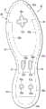
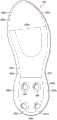
图6是室的俯视图。Figure 6 is a top view of the chamber.
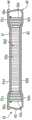
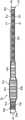
图7是室的外侧面正视图。Figure 7 is a front view of the outer side of the chamber.
图8A-8D是室的如通过图6中的剖面线8A-8A至8D-8D所定义的剖视图。8A-8D are cross-sectional views of the chamber as defined by
图9是可以用于制造室的工艺的模具的透视图。Figure 9 is a perspective view of a mold that may be used in the process of making the chamber.
图10A-10E是模具的侧面正视图,描绘了在制造室的工艺中的步骤。10A-10E are side elevational views of the mold depicting steps in the process of making the chamber.
图11A-11E是模具的如通过图10A-10E中的剖面线11A-11A至11E-11E所定义的示意性剖视图,描绘了在用于制造室的工艺中的步骤。11A-11E are schematic cross-sectional views of a mold, as defined by
图12A-12H是相应于图6且描绘了室的另外构型的俯视图。12A-12H are top views corresponding to FIG. 6 and depicting additional configurations of chambers.
图13A-13E是相应于图8D且描绘了室的另外构型的剖视图。13A-13E are cross-sectional views corresponding to FIG. 8D and depicting additional configurations of chambers.
图14是相应于图8C且描绘了室的另外构型的剖视图。Figure 14 is a cross-sectional view corresponding to Figure 8C and depicting an additional configuration of the chamber.
图15是相应于图8B且描绘了室的另外构型的剖视图。Figure 15 is a cross-sectional view corresponding to Figure 8B and depicting an additional configuration of the chamber.
图16A-16B是结合有流体填充室的其它物品的透视图。16A-16B are perspective views of other articles incorporating fluid-filled chambers.
图17是流体填充室的可选择的构型的俯视图。Figure 17 is a top view of an alternative configuration of a fluid-filled chamber.
图18是室的可选择的构型的内侧面正视图。Figure 18 is a medial side elevation view of an alternative configuration of the chamber.
详细描述A detailed description
以下的讨论和附图公开了流体填充室的各种构型及用于制造室的方法。虽然参照具有适合于跑步的构型的鞋类公开了室,但是与室相关的概念可以应用于宽范围的运动鞋类的样式,包括例如篮球鞋、交叉训练鞋、足球鞋、高尔夫球鞋、登山鞋和靴子、滑雪和滑雪板靴、英式足球鞋、网球鞋和步行鞋。与室相关的概念还可以与通常被认为是非运动的鞋类类型一起使用,包括礼服鞋、休闲鞋和凉鞋。除鞋类之外,室可以结合到其他类型的服装和运动装备中,包括用于诸如足球和曲棍球的运动的头盔、手套和保护性垫料。相似的室还可以结合到在家庭用品和工业产品中利用的缓冲物和其他的可压缩结构中。因此,包含本文公开的概念的室可以与多种产品一起使用。The following discussion and figures disclose various configurations of fluid-filled chambers and methods for fabricating the chambers. Although chambers are disclosed with reference to footwear having a configuration suitable for running, chamber-related concepts can be applied to a wide range of styles of athletic footwear, including, for example, basketball shoes, cross-training shoes, soccer shoes, golf shoes, Shoes and boots, ski and snowboard boots, football boots, tennis shoes and walking shoes. Room-related concepts can also be used with footwear types that are generally considered non-athletic, including dress shoes, loafers, and sandals. In addition to footwear, chambers can be incorporated into other types of clothing and sports equipment, including helmets, gloves, and protective padding for sports such as football and hockey. Similar chambers may also be incorporated into cushioning and other compressible structures utilized in household and industrial products. Thus, chambers incorporating the concepts disclosed herein can be used with a variety of products.
一般的鞋类结构General Footwear Construction
在图1-3B中,鞋类物品10被描绘为包括鞋面20和鞋底结构30。为了参照的目的,鞋类10可以大致分为三个区域:鞋前部区11、鞋中部区12和鞋跟区13,如图1中所示的。鞋前部区11大体上包括鞋类10的相应于脚趾以及将跖骨与趾骨连接的关节的部分。鞋中部区12大体上包括鞋类10的相应于足部的足弓区域的部分。鞋跟区13大体上包括鞋类10的相应于足部的后部部分的部分,包括跟骨。区11-13不意在划分鞋类10的精确区域。而是,区11-13意在代表鞋类10的大体区域以帮助以下的讨论。除被应用到鞋类10之外,区11-13还可应用到鞋面20、鞋底结构30及其个别的元件。鞋类10还包括外侧面14和内侧面15,如图2-3B所示的。外侧面14和内侧面15还延伸穿过区11-13中的每一个且相应于鞋类10的相对侧面。与区11-13一样,侧面14和15表示鞋类10的大体区域以帮助以下的讨论,且除应用到鞋类10以外,侧面14和15还可应用到鞋面20、鞋底结构30及其个别的元件。In FIGS. 1-3B , article of
鞋面20被描绘为具有结合有多种材料元件(例如织物、泡沫、皮革和合成皮革)的实质上常见的构型,该多种材料元件被缝合、粘附、结合或以其他方式联结到一起以形成用于牢固地且舒适地容纳足部的内部空腔。可以关于鞋面20来选择和定位材料元件,以选择性地赋予例如耐久性、透气性、耐磨性、柔性和舒适性的性质。鞋跟区13中的踝开口21提供内部空腔的入口。此外,鞋面20可以包括鞋带22,鞋带22用于以常规的方式改变内部空腔的尺寸,从而将足部固定在内部空腔内并且有助于足部进入内部空腔和从内部空腔移除。鞋带22可以延伸穿过鞋面20中的孔,且鞋面20的舌状部分可以在内部空腔和鞋带22之间延伸。鞋面20还可以结合有鞋垫(sockliner)23,鞋垫23定位在鞋面20中的空腔内且毗邻足部的足底(即,下)表面定位以增强鞋类10的舒适性。考虑到本申请的各个方面主要地涉及鞋底结构30,鞋面20可以呈现上文讨论的一般构型或实际上任何其他常规的或非常规的鞋面的一般构型。因此,鞋面20的总体结构可以显著地变化。
鞋底结构30固定到鞋面20且具有在鞋面20和地面之间延伸的构型。因此,实际上,鞋底结构30被定位为在足部和地面之间延伸。除减弱地面反作用力(即,为足部提供缓冲)之外,鞋底结构30可以提供附着摩擦力、赋予稳定性并限制各种足部运动,例如内旋。鞋底结构30的主要元件是鞋底夹层31和鞋外底32。鞋底夹层31可以结合有聚合物泡沫材料,例如聚氨基甲酸酯或乙烯醋酸乙烯酯。鞋底夹层31还可以结合有流体填充室33。除聚合物泡沫材料和室33之外,鞋底夹层31可以结合有增强鞋类10的舒适性、性能或地面反作用力衰减性质的一个或多个另外的鞋类元件,包括板、调节器、耐用元件或运动控制构件。
可以不存在于鞋类10的某些构型中的鞋外底32固定到鞋底夹层31的下表面上且形成鞋类10的与地面接触的表面的至少一部分。鞋外底32可以由提供用于接合地面的耐久且耐磨的表面的橡胶材料形成。此外,鞋外底32还可以具有纹理以增强鞋类10和地面之间的附着摩擦力(即,摩擦力)性质。在另外的构型中,且取决于鞋底夹层31结合有聚合物泡沫材料、室33或两者的方式,鞋外底32可以单独地固定到聚合物泡沫材料、单独地固定到室33或固定到聚合物泡沫材料和室33两者。
由于结合到鞋类10中,室33具有从鞋前部区11至鞋跟区13且还从外侧面14至内侧面15延伸穿过实质上整个鞋类10的形状,从而具有相应于足部的轮廓且实质上在整个足部的下方延伸的形状。因此,当足部定位在鞋面20内时,室33在足部的下方延伸,以在各种步行活动比如跑步和走路期间衰减在鞋底结构30被压缩在足部和地面之间时所产生的地面反作用力。在其他的构型中,室33可以延伸穿过少于整个鞋类10。例如,室33可以只延伸穿过鞋前部区11、或只延伸穿过鞋中部区12、或只延伸穿过鞋跟区13。可选择地,室33可以只延伸穿过鞋类10的外侧面14或仅延伸穿过鞋类10的内侧面15。室33还可以延伸穿过区和侧面的任意组合。也就是说,在各种构型中,室33可以延伸穿过鞋类10的任意部分。Due to its incorporation into
如图1-3B中所描绘的,室33定位在鞋底夹层31的聚合物泡沫材料下方,且固定到聚合物泡沫材料并固定到鞋外底32。然而,在一些构型中,室33可以位于鞋底夹层31的聚合物泡沫材料上方、位于鞋底夹层31的聚合物泡沫材料的层之间、至少部分地通过鞋底夹层31的聚合物泡沫材料封装,或甚至实质上被鞋底夹层31的聚合物泡沫材料围绕或完全地封装在鞋底夹层31的聚合物泡沫材料内,如图3A所描绘的。在其它构型中,室33可以固定到板23或鞋底夹层31内的其它结构。在另外的构型中,可以不存在鞋底夹层31的聚合物泡沫材料,且室33可以固定到鞋面20和鞋外底32两者。因此,室33的整体形状及室33结合到鞋类10中的方式可以显著地变化。As depicted in FIGS. 1-3B ,
尽管室33被描绘且讨论为鞋类10内的密封室,但是室33也可以是鞋类10内的流体系统的部件。更具体地,泵、管道及阀可以与室33联结,以提供用来自于鞋类10的外部或鞋类10内的储存器的空气使室33加压的流体系统。作为示例,室33可以结合在Passke等人的美国专利第7,210,249号和Dojan等人的美国专利第7,409,779号中公开的流体系统中的任一种来使用。Although
室构型chamber configuration
在图4-8D中分别地描绘了以适合于鞋类应用的初始构型的室33。室33具有带轮廓的构型(contoured configuration),且当结合到鞋类10中时,室33相应于实质上整个鞋类10。当足部定位在鞋面20内时,室33在足部的下方延伸,以便在各种步行活动比如跑步和走路期间,衰减在鞋底结构30被压缩在足部和地面之间时所产生的地面反作用力。在其他的构型中,室33可以具有交替延伸,比如例如在足部的足前部区或足部的足跟区的下方延伸。此外,尽管室33被描绘成暴露在鞋类10的外侧面14和内侧面15两者上,但是在鞋类10的一些构型中,鞋底夹层31的聚合物泡沫材料可以形成鞋底夹层31的侧壁的至少一部分。
室33的主要元件为外部阻挡物40和抗拉结构50a-50d。阻挡物40(a)形成室33的外部,(b)限定容纳加压流体和抗拉结构50a-50d两者的内部空腔,且(c)提供用于将加压流体保留在室33内的耐用的密封阻挡物。阻挡物40的聚合物材料包括:(a)朝着鞋面20定向的第一阻挡物部分41,第一阻挡物部分41可以形成阻挡物40的上部分;(b)朝着鞋外底32定向的相对的第二阻挡物部分42,第二阻挡物部分42可以形成阻挡物40的下部分;以及(c)围绕室33的周边并且在阻挡物部分41和42之间延伸的周边边缘43。The main elements of the
如图4-8D中所描绘的,抗拉结构50a-50d定位在内部空腔内且可以为抗拉构件,比如织物抗拉构件。在其他构型中,抗拉结构可以包括不是织物抗拉构件的元件,比如在Peyton的序列号为12/630,642的美国专利申请以及Peyton的序列号为12/777,167的美国专利申请系列中公开的拴系元件(tether element)中的任一种。在一些构型中,抗拉构件50可以由泡沫抗拉构件形成或形成为包括泡沫抗拉构件,泡沫抗拉构件比如在Schindler的美国专利第7,131,218号、Schindler等人的美国专利第7,588,654号及Schindler等人的美国专利第7,591,919号中公开的泡沫抗拉构件中的任何。As depicted in Figures 4-8D,
抗拉结构50a-50d可以分别包括上抗拉层51a-51d、相对的下抗拉层52a-52d以及在抗拉层51a-51d和52a-52d之间延伸的多个连接构件53a-53d。上抗拉层51a-51d固定到第一阻挡物部分41的内表面且下抗拉层52a-52d固定到第二阻挡物部分42的内表面。连接构件53a-53d可以包括由各种材料形成的纱线、纤维或细丝,且可以以相对稀疏的密度、相对紧密的(packed)密度或任意其它密度跨过抗拉结构52a-52d的长度和宽度定位。尽管下文更加详细地讨论,但是可以利用粘合剂结合或热结合,以将抗拉结构50a-50d固定到阻挡物40。抗拉结构50a-50d可以定位在室33的不同区域中且可以具有不同的高度。
宽范围的聚合物材料可以被用于阻挡物40。在选择用于阻挡物40的材料时,可以考虑材料的工程性质(例如,抗拉强度、拉伸性质、疲劳特性、动态模量和损耗角正切)以及材料阻止阻挡物40所包含的流体扩散的能力。当例如由热塑性氨基甲酸乙酯形成时,阻挡物40可以具有约1.0毫米的厚度,但是厚度可以例如从小于0.25变化至大于2.0毫米。除热塑性氨基甲酸乙酯外,可以适合于阻挡物40的聚合物材料的示例包括聚氨基甲酸酯、聚酯、聚酯型聚氨基甲酸酯和聚醚型聚氨基甲酸酯。阻挡物40还可以由包括热塑性聚氨基甲酸酯和乙烯-乙烯醇共聚物的交替层的材料形成,如在Mitchell等人的美国专利第5,713,141号和第5,952,065号中所公开的。还可以利用基于该材料的变化形式,其中中心层由乙烯-乙烯醇共聚物形成,毗邻于中心层的层由热塑性聚氨基甲酸酯形成,并且外层由热塑性聚氨基甲酸酯和乙烯-乙烯醇共聚物的再磨研材料形成。用于阻挡物40的其它合适的材料是包括气体阻挡材料和弹性材料的交替层的柔性微层膜,如在Bonk等人的美国专利第6,082,025号和第6,127,026号中公开的。另外的合适材料在Rudy的美国专利第4,183,156号和第4,219,945号中公开。另外的合适材料包括含有晶体材料的热塑性薄膜,如在Rudy的美国专利第4,936,029号和第5,042,176号中公开的,以及包括聚酯多元醇的聚氨基甲酸酯,如在Bonk等人的美国专利第6,013,340号、第6,203,868号和第6,321,465号中公开的。A wide range of polymeric materials can be used for
可以利用各种工艺来制造室33。一般而言,制造工艺包含(a)将形成阻挡物部分41和42及周边边缘43的一对聚合物片材固定到抗拉结构50a-50d的相对侧(即,固定到抗拉层51a-51d和52a-52d),以及(b)形成周边结合部44,周边结合部44联结聚合物片材的周边且可以围绕周边边缘43延伸。周边结合部44被描绘为毗邻室33的上表面,但其可以定位在室33的上表面和下表面之间,或可以毗邻室33的下表面。热成型工艺还可以包含(a)将抗拉结构50a-50d定位在室33内,以及(b)将抗拉结构50a-50d结合到阻挡物物部分41和42中的每一个。尽管大体上全部热成型工艺可以用模具来进行,如在下文更加详细地描述的,但是工艺的各个部分或步骤中的每一个可以在形成室33时单独地进行。也就是说,可以利用各种其它方法来形成室33。
为了有助于抗拉结构50a-50d和阻挡物40之间的结合,聚合物补充层可以被应用到抗拉层51a-51d和52a-52d中的任何。当加热时,补充层软化、熔化或以其他方式开始改变状态,使得与阻挡物部分41和42的接触引起来自于阻挡物40和补充层中的每一个的材料混合或以其他方式彼此联结。因此,在冷却时,补充层与阻挡物40永久地联结,从而将抗拉结构50a-50d与阻挡物40联结。在一些构型中,热塑性的线或条可以存在于抗拉层51a-51d和52a-52d内,以有助于与阻挡物40的结合,如在Thomas等人的美国专利第7,070,845号中所公开的,或者可以使用粘合剂使阻挡物40固定到抗拉结构50a-50d中的任何。To facilitate the bond between
在热成型工艺后,或作为热成型工艺的一部分,流体可以被注入到内部空腔中并被加压在零和三百五十千帕(即,约每平方英寸五十一磅)或更大之间。加压流体将向外的力施加在阻挡物40上,这趋向于分开阻挡物部分41和42。然而,抗拉结构50a-50d固定到阻挡物部分41和42中的每一个,以便在加压时将预期形状强加在室33上。更具体地,通过加压流体施加在阻挡物40上的向外的力,延伸穿过内部空腔的连接构件53a-53d被受拉地放置,从而防止阻挡物40向外扩张且使得室33保持预期形状。周边结合部44联结聚合物片材以形成防止流体逃逸的密封件,而抗拉结构50a-50d防止阻挡物40由于流体的压力而造成的向外扩展或以其它方式的扩张。也就是说,抗拉结构50a-50d有效地限制室33的扩展,以保持阻挡物部分41和42的预期形状。After, or as part of, the thermoforming process, fluid can be injected into the interior cavity and pressurized between zero and three hundred and fifty kilopascals (ie, approximately fifty-one pounds per square inch) or more between large. The pressurized fluid exerts an outward force on
多个连接构件53a-53d中的每一个内的连接构件的长度在整个抗拉结构50a-50d上是大体上恒定的,这赋予抗拉层51a-51d和52a-52d中的每一个平行的构型。然而,在一些构型中,多个连接构件53a-53d中的至少一个内的连接构件的长度可以变化,以赋予室33带轮廓的构型。例如,由于多个连接构件53a-53d中的每一个内的连接构件的长度不同,室33可以是锥形的或可以形成凹陷部。带轮廓的抗拉结构的示例在Dua的序列号为12/123,612的美国专利申请和Rapaport等人的序列号为12/123,646的美国专利申请中公开。此外,抗拉结构50a-50d可以包括抗拉构件,比如织物抗拉构件。也就是说,抗拉结构50a-50d中的至少一个的一部分可以由织物抗拉构件形成。织物抗拉构件可以自间隔织物的较大元件切割或由间隔织物的较大元件形成。可选择地,例如通过如Dua的序列号为12/123,612的美国专利申请中的横编工艺(flat-knitting process),抗拉元件51a-51d和52a-52d中的每一个可以形成为具有各种构型。The length of the connecting members within each of the plurality of connecting
合适地配置的抗拉结构50a-50d可以具有一系列构型中的任何,包括在Dua的美国专利申请第12/123,612号、Rapaport等人的美国专利申请第12/123,646号及Peyton的美国专利申请第12/630,642号中公开的一系列构型。在一些构型中,室33可以结合有允许个人调节流体压力的阀或其它结构。此外,室33可以结合到根据例如穿着者的跑步方式或体重来改变阻挡物40内的压力的流体系统中,该流体系统类似于在Dojan等人的美国专利第7,409,779中公开的流体系统。Properly configured
如图4-8D中所描绘的,室33及室33内的抗拉结构50a-50d大体上在整个鞋类10上延伸。抗拉结构50a-50d定位在室33的不同区域中,或定位在形成室33的外部且界定室33内的内部空腔的阻挡物40的不同区域中。抗拉结构50a定位在室33的第一区域中,或者定位在阻挡物40的第一区域中且在内部空腔内。抗拉结构50b定位在室33的第二区域中,或者定位在阻挡物40的第二区域中且在内部空腔内。抗拉结构50b大体上位于鞋类10的鞋跟区13中,且抗拉结构50a在抗拉结构50b后面。抗拉结构50c定位在室33的第三区域中,或者定位在阻挡物40的第三区域中且在内部空腔内。抗拉结构50c至少部分地定位在鞋类10的鞋中部区12。抗拉结构50c包括外侧段(lateral segment)55a和相似范围的内侧段55b。最后,抗拉结构50d定位在室33的第四区域中,或者定位在阻挡物40的第四区域中且在内部空腔内。抗拉结构50d定位在抗拉结构50c前面且至少部分地定位在外侧段55a和内侧段55b之间。第一区域、第二区域、第三区域和第四区域彼此流体相通。As depicted in FIGS. 4-8D ,
此外,抗拉结构50a-50d中的每一个可以具有与其他抗拉结构50a-50d的高度不同的高度。抗拉结构50a具有比抗拉结构50b的高度小的高度。抗拉结构50b具有比抗拉结构50c的高度大的高度。最后,抗拉结构50c具有比抗拉结构50d的高度大的高度。转而,抗拉结构50a-50d的相对位置和高度差赋予鞋类10带轮廓的构型。如图4-8D中所描绘的,抗拉结构50a-50d的相对位置和高度差赋予包括鞋跟斜面和鞋前部袋状物的轮廓。Additionally, each of
如图4-8D中所描绘的,抗拉结构50a-50d彼此毗邻。也就是说,抗拉结构50a-50d紧挨着彼此定位,使得每一个抗拉结构50a-50d的至少一部分直接接触其它抗拉结构50a-50d中的一个或多个或者与其它抗拉结构50a-50d中的一个或多个最低限度地隔开。然而,在一个抗拉结构50a-50d具有比另一个附近的抗拉结构50a-50d的高度大的高度的情况下,室33的在具有较大高度的抗拉结构的区域中的一部分可以具有由具有较小高度的附近抗拉结构所施加的形状,而不是由具有较大高度的抗拉结构所施加的形状。因此,在一些构型中,抗拉结构可以被间隔开,且抗拉结构在其中被间隔开的区域中的室33的一部分仍然可以具有由具有较小高度的附近抗拉结构所施加的形状。As depicted in Figures 4-8D,
在一些构型中,外部阻挡物的一个或多个部分可以形成为包括模制高度梯度(molded height gradient)。定位在结合不同高度的抗拉结构的两个区域之间的模制高度梯度可以将在充气的室的两个区域之间赋予的高度差集中在室的一个阻挡物部分上。在各种构型中,阻挡物部分41或42可以模制或以其他方式形成为在至少部分地紧邻至少两个抗拉结构处,比如在抗拉结构之间的位置处,包括模制高度梯度58。例如,如图4-8D所描绘的,第二阻挡物部分42形成为包括紧邻抗拉结构50b和50c且在抗拉结构50b和50c之间定位的模制高度梯度58。反过来,室33的结合有抗拉结构50b的区域和室33的结合有抗拉结构50c的区域之间的在第二阻挡物部分42上的高度差可以大于在第一阻挡物部分41上的高度差。因此,模制高度梯度58可以将室33的结合有抗拉结构50b和50c的不同区域之间的从室33向外延伸上的变化集中在室33的下表面处。In some configurations, one or more portions of the outer barrier may be formed to include a molded height gradient. A molded height gradient positioned between two regions incorporating tensile structures of different heights can focus the height difference imparted between two regions of an inflated chamber on one barrier portion of the chamber. In various configurations,
尽管在图4-8D中被描绘成包括四个抗拉结构50a-50d,但是室33的各种构型可以包括较少的抗拉结构。在一些构型中,室33可以结合有至少第一抗拉结构和第二抗拉结构。室33的抗拉结构可以定位在室33的不同区域中,或者定位在阻挡物40的不同区域中且在内部空腔内,并且室33的抗拉结构可以具有不同的高度。例如,室33可以结合有定位在第一区域中且具有第一高度的第一抗拉结构,且可以结合有定位在第二区域中且具有第二高度的第二抗拉结构,第一高度大于第二高度。在一些构型中,第一抗拉结构和第二抗拉结构可以各自为带轮廓的、锥形的或以其它方式形成为具有多于一个高度的单一抗拉结构的一部分,其中第一抗拉结构通过至少一个内部结合部至少部分地与第二抗拉结构分开。也就是说,第一抗拉结构中的某一部分和第二抗拉结构的某一部分可以通过至少一个内部结合部至少部分地分开。Although depicted in Figures 4-8D as including four
可选择地,第一抗拉结构可以在靠近第二抗拉结构的第一部分处具有第一高度,且第二抗拉结构可以在靠近第一抗拉结构的第二部分处具有第二高度,第二高度大于第一高度。也就是说,尽管第一抗拉结构和第二抗拉结构两者可以具有大体上扁平的构型,但是第一抗拉结构和第二抗拉结构中的任一个或两个可以是带轮廓的,或者可以以其他方式具有多于一个高度,且第二抗拉结构的至少在靠近第一抗拉结构的一个点处的高度可以大于第一抗拉结构的至少在靠近第二抗拉结构的一个点处的高度。Alternatively, the first tensile structure may have a first height proximate a first portion of the second tensile structure, and the second tensile structure may have a second height proximate a second portion of the first tensile structure, The second height is greater than the first height. That is, although both the first tensile structure and the second tensile structure may have a generally flat configuration, either or both of the first tensile structure and the second tensile structure may be contoured or may otherwise have more than one height, and the height of the second tensile structure at least at one point near the first tensile structure may be greater than that of the first tensile structure at least at a point near the second tensile structure The height at a point of .
室33也可以实质上没有内部结合部,即,没有与室33的周边边缘向内隔开的结合部。因此,第一抗拉结构所定位的室33的第一区域和第二抗拉结构所定位的室33的第二区域可以流体相通。例如,室33可以实质上没有第一抗拉结构的靠近第二抗拉结构的第一部分和第二抗拉结构的靠近第一抗拉结构的第二部分之间的内部结合部。
可选择地,室33可以包括第一抗拉结构的靠近第二抗拉结构的第三部分和第二抗拉结构的靠近第一抗拉结构的第四部分之间的至少一个内部结合部。也就是说,室33可以在第一抗拉结构和第二抗拉结构之间的一个区域处实质上没有内部结合部,但是室33可以在第一抗拉结构和第二抗拉结构之间的第二区域处包括一个或多个内部结合部。Alternatively,
类似地,尽管在图4-8D中被描绘成包括四个抗拉结构50a-50d,但是结合到鞋类物品中的室33的各种构型可以包括较少的抗拉结构,且那些抗拉结构在室33内的位置和相对高度也可以变化。在鞋类的一些构型中,室33可以结合有第一抗拉结构和第二抗拉结构,第一抗拉结构在靠近第二抗拉结构的第一部分处具有第一高度,第二抗拉结构在靠近第一抗拉结构的第二部分处具有第二高度,第二高度大于第一高度。Similarly, although depicted in FIGS. 4-8D as including four
在这样的构型中,第一抗拉结构可以至少部分地定位在鞋类的鞋跟区中,且第二抗拉结构可以至少部分地定位在鞋类的鞋中部区中。In such configurations, the first tensile structure can be at least partially positioned in a heel region of the footwear, and the second tensile structure can be at least partially positioned in a midfoot region of the footwear.
可选择地,在这样的构型中,第二抗拉结构可以定位在鞋类的至少鞋跟区中,且第一抗拉结构可以定位在第二抗拉结构后面。这样的构型还可以包括定位在外部阻挡物内的在靠近第二抗拉结构的第三部分处具有第三高度的第三抗拉结构,第三高度小于第二高度,且第三抗拉结构定位在第二抗拉结构前面。Alternatively, in such a configuration, the second tensile structure can be positioned in at least the heel region of the footwear, and the first tensile structure can be positioned behind the second tensile structure. Such configurations can also include a third tensile structure positioned within the outer barrier having a third height adjacent to a third portion of the second tensile structure, the third height being less than the second height, and the third tensile structure The structure is positioned in front of the second tensile structure.
作为另一种可选择方案,在这样的构型中,第一抗拉结构可以定位在鞋类的至少鞋中部区中,且第二抗拉结构可以定位在第一抗拉结构前面。这样的构型的第一抗拉结构还可以包括外侧段和内侧段,且第二抗拉结构可以至少部分地定位在外侧段和内侧段之间。As another alternative, in such a configuration, a first tensile structure may be positioned in at least a midfoot region of the footwear, and a second tensile structure may be positioned forward of the first tensile structure. The first tensile structure of such a configuration can also include a lateral segment and a medial segment, and the second tensile structure can be at least partially positioned between the lateral segment and the medial segment.
在鞋类的其它构型中,室33可以结合有在第一区域中具有第一高度的第一抗拉结构和在第二区域中具有第二高度的第二抗拉结构,第二高度大于第一高度。在这样的构型中,第二抗拉结构可以定位在鞋类的至少鞋跟区中,且第一抗拉结构可以被定位在第二抗拉结构后面,作为鞋类的鞋跟斜面结构的一部分。In other configurations of footwear,
在鞋类的一些构型中,室33可以结合有在第一区域中具有第一高度的第一抗拉结构和在第二区域中具有第二高度的第二抗拉结构,第二高度小于第一高度。在这样的构型中,第一抗拉结构可以定位在鞋类的至少鞋中部区中,且第二抗拉结构可以定位在第一抗拉结构前面。In some configurations of footwear,
在鞋类的其它构型中,室33可以结合有在室33的第一区域中定位在外部阻挡物内的第一抗拉结构、在室33的第二区域中定位在外部阻挡物内的第二抗拉结构以及在室33的第三区域中定位在外部阻挡物内的第三抗拉结构。在这样的构型中,第一区域可以位于室的最后面的区中且可以具有第一高度,室的第二区域可以位于室的最后面的区和室的最前面的区之间且可以具有大于第一高度的第二高度,且室的第三区域可以位于室的最前面的区中且可以具有小于第二高度的第三高度。这样的构型中的第二抗拉结构还可以包括外侧段和内侧段,且第三抗拉结构可以至少部分地定位在外侧段和内侧段之间。In other configurations of footwear, the
换而言之,在各种构型中,具有不同高度的两个或更多的抗拉结构可以结合到室33的不同区域中。一个或多个抗拉结构可以定位在室33的鞋跟区中或在鞋中部区中或在鞋前部区中,且一个或多个其他的抗拉结构可以定位在室33的不同区域中。此外,结合到室33中的抗拉结构可以具有各种形状。例如,在各种构型中,抗拉结构可以具有外侧段或内侧段,其中抗拉结构的一个或多个内侧部分或外侧部分相对于抗拉结构的多个中心部分,即抗拉结构的外侧部分和内侧部分之间的抗拉结构的部分,进一步向前、进一步向后或进一步向前且向后地延伸。In other words, in various configurations, two or more tensile structures having different heights may be incorporated into different regions of
上文描述的室33的各种构型可以结合到多种其它产品中的任一种或鞋类物品中,比如衣服、运动设备、缓冲物及其它可压缩结构。通过将具有不同高度的多个抗拉结构结合到室33的不同区域中,可以改变室33的一种或多种性质,比如室33的柔性、刚度、硬度、拉伸响应、可压缩性或力衰减性质。此外,可以在不使用其自身是锥形的或带轮廓的抗拉结构的情况下赋予室33锥形或轮廓。The various configurations of
制造工艺manufacturing process
尽管可以利用各种制造工艺来形成室33,但是现在将讨论合适的热成型工艺的示例。参考图9,可以在热成型工艺中使用的模具60被描绘成包括上模具部分61和下模具部分62。模具60用于由被模制且结合以界定阻挡物部分41和42及周边边缘43的一对聚合物片材来形成室33,且热成型工艺将抗拉结构50a-50d固定在阻挡物40内。更具体地,模具60(a)赋予聚合物片材中的一个聚合物片材形状以便形成第一阻挡物部分41、(b)赋予聚合物片材中的另一个聚合物片材形状以便形成第二阻挡物部分42、(c)赋予聚合物片材形状以便形成周边边缘43并形成用来联结聚合物片材的周边的周边结合部44、(d)将抗拉结构50a-50d定位在室33内以及(e)将抗拉结构50a-50d结合到阻挡物部分41和42中的每一个。Although various manufacturing processes may be utilized to form
在这个示例性制造工艺中,抗拉结构50a-50d中的每一个可以是织物抗拉构件。在其它制造工艺中,抗拉结构50a-50d中的每一个可以包括一个或多个织物抗拉构件,且还可以包括不是织物抗拉构件的一个或多个元件,比如拴系元件。In this exemplary manufacturing process, each of
制造工艺的准备中,可以得到并组织形成室33的各种元件。例如,形成阻挡物40的上聚合物层71和下聚合物层72可以被切割成所需形状。抗拉结构50a-50d在制造工艺的这个阶段中处于压缩状态下,其中织物层51a-51d和52a-52d毗邻于彼此地放置且连接构件53a-53d处于收缩状态下。在完成该制造工艺时,当室33被加压时,抗拉结构50a-50d被受拉地放置,这使织物层51a-51d和52a-52d彼此隔开且引起连接构件53a-53d变直。In preparation for the manufacturing process, the various
在制造室33时,上聚合物层71、下聚合物层72及抗拉结构50a-50d中的一个或多个被加热至有助于部件之间的结合的温度。根据用于抗拉结构50a-50d和形成阻挡物40的聚合物层71和72的特定材料,合适的温度可以在120至200摄氏度(248至392华氏度)或更大的范围内。可以利用各种辐射加热器或其它装置来加热室33的部件。在一些制造工艺中,模具60可以被加热,使得模具60和室33的部件之间的接触使部件的温度升高至有助于结合的水平。During fabrication of
加热后,室33的部件定位在模具部分61和62之间,如图10A和图11A所描绘的。为了正确地定位部件,可以利用梭状框架(shuttle frame)或其它装置。一旦定位,模具部分61和62就朝向彼此平移并且开始闭合在部件上,使得(a)上模具部分61接触上聚合物层71、(b)下模具部分62的下脊部64接触下聚合物层72,且(c)聚合物层71和72开始围绕抗拉结构50a-50d弯曲以便延伸到模具60内的腔中,如图10B和图11B所描绘的。部件从而被相对于模具60定位且已经发生初始的成形和定位。After heating, the components of
在图10B和图11B中所描绘的阶段中,空气可以从围绕聚合物层71和72的区域穿过模具部分61和62中的各个真空口部分地排出。排出空气的目的是将聚合物层71和72拉动成与模具60的各个轮廓接触。这确保了聚合物层71和72按照模具60的轮廓恰当地成形。注意到,聚合物层71和72可以拉伸以便围绕抗拉构件50a-50d延伸并且延伸到模具60中。与室33中的阻挡物40的厚度相比,聚合物层71和72可以呈现更大的初始厚度。聚合物层71和72的初始厚度和阻挡物40的最终厚度之间的这种差异可能由于在热成型工艺的该阶段中发生的拉伸而发生。In the stages depicted in FIGS. 10B and 11B , air may be partially exhausted from the area surrounding polymer layers 71 and 72 through various vacuum ports in
被多个弹簧66支撑的可移动插入物65可以压下以将特定程度的压力置于部件上,从而使聚合物层71和72结合到抗拉结构50a-50d的相对表面。可移动插入物65包括由下聚合物层72形成周边边缘43的周边压痕67。可移动插入物65还可以包括一个或多个高度梯度68。在室33膨胀之前,高度梯度68可以在室33的一个或多个不同区域中赋予室33的表面高度差。进而,在室33膨胀后,这样的高度差可以在室33的该表面处集中室33的不同区域之间的高度变化。在模具60的一些构型中,可以不存在可移动插入物65和弹簧66,且诸如周边压痕67和高度梯度68的特征部可以代替地结合到下模具部分62中。而且,在模具60的一些构型中,诸如周边压痕67和高度梯度68的特征部的部分也可以结合到上模具部分61上,或者代替地结合到可移动插入物65或下模具部分62中。The
随着模具60进一步闭合,上模具部分61和脊部64使上聚合物层71结合到下聚合物层72,如图10C和图11C所描绘的,从而形成周边结合部44。而且,脊部64的延伸远离抗拉结构50a-50d的部分形成聚合物层71和72的其它区域之间的结合部,有助于充气导管73的形成。As
为了提供用于将聚合物层71和72拉动成与模具60的各个轮廓接触的第二方式,在聚合物层71和72之间且紧邻抗拉结构50a-50d的区域可以被加压。在这个方法的准备阶段期间,注射针可以定位在聚合物层71和72之间,且注射针可以定位为使得脊部64在模具60闭合时包围注射针。然后气体可以从注射针喷射出,使得聚合物层71和72接合脊部64。从而,可以在聚合物层71和72之间形成充气导管73(参见图10D)。然后气体可以穿过充气导管73,从而进入且加压紧邻抗拉结构50a-50d且在聚合物层71和72之间的区域。结合真空,内部压力确保聚合物层71和72接触模具60的各个表面。To provide a second means for pulling
如上文讨论的,聚合物材料的补充层或热塑性线可以应用到织物层51a-51d和52a-52d,以便有助于抗拉结构50a-50d和阻挡物40之间的结合。由可移动插入物65施加在部件上的压力确保了补充层或热塑性线与聚合物层71和72形成结合部。As discussed above, supplemental layers of polymeric material or thermoplastic threads may be applied to
当完成结合时,模具60被打开,且室33和聚合物层71和72的多余部分被移除并被允许冷却,如图10D和11D中所描绘的。流体可以通过充气针和充气导管73注射到室33中。在离开模具60时,抗拉结构50a-50d保持在压缩构型下。然而,当室33被加压时,流体将向外的力置于阻挡物40上,这趋向于分开阻挡物部分41和42,从而使抗拉结构50a-50d受拉地放置且赋予室33带轮廓的构型。此外,利用密封工艺,以在加压后密封毗邻室33的充气导管73。然后移除聚合物层71和72的多余部分,从而完成室33的制造,如图10E和图11E所描绘的。作为可选择的方案,充气和移除多余材料的顺序是可以颠倒的。作为工艺中的最后步骤,室33可以被检测且然后结合到鞋类10的鞋底夹层31中。When bonding is complete,
另外的构型another configuration
如图4-8D中所描绘的,抗拉结构50a-50d中的每一个延伸遍及室33的一组不同区域中的一个。换而言之,抗拉结构50a-50d的从其周边向内定位的部分没有被内部结合部中断。然而,在其它构型中,内部结合部可以延伸穿过缝隙,比如室33的抗拉结构中的孔。例如,如图12A中所描绘的,内部结合部56a-56c延伸穿过抗拉结构50b-50d中的缝隙57a-57c,以使第一阻挡物层41联结到第二阻挡物层42。As depicted in FIGS. 4-8D , each of
如图4-8D中所描绘的,抗拉结构50a-50d彼此毗邻,且室33实质上没有在抗拉结构50a-50d之间的内部结合部。在其它构型中,抗拉结构之间的内部结合部可以延伸穿过抗拉结构中的缝隙,比如抗拉结构中的孔或凹部。例如,如图12B中所描绘的,内部结合部56a从周边结合部44向内穿过抗拉结构50a中的缝隙57a延伸到室33的内部。抗拉结构50a形成为具有在第一部分处的第一高度和在第二部分处的第二高度,第二高度大于第一高度,且内部结合部56a使第一部分和第二部分分开。此外,内部结合部56b延伸穿过具有凸形形状且由抗拉结构50a和抗拉结构50b中的凹部配合地形成的缝隙57b,且内部结合部56c延伸穿过具有非凸形形状且由抗拉结构50b和抗拉结构50c中的凹部配合地形成的缝隙57c。As depicted in Figures 4-8D,
如图4-8D中所描绘的,抗拉结构50a-50d中的每一个具有实质上扁平的构型且结合有相对一致的高度的连接构件53a-53d。在其它构型中,连接构件53a-53d中的任何的长度可以变化,或者一个或多个抗拉结构可以是带轮廓的、锥形的或以其他方式形成为具有多于一个高度。例如,如图12C和图13A中所描绘的,抗拉结构50b的轮廓制定成在鞋跟区13中具有比在鞋中部区12和鞋前部区11中的高度大的高度。As depicted in Figures 4-8D, each of
如图4-8D中所描绘的,抗拉结构50a-50d紧挨着彼此定位,使得每一个抗拉结构50a-50d的部分直接地接触其它抗拉结构50a-50d或与其它抗拉结构50a-50d最低限度地隔开。在其它构型中,缝隙或间隔可以至少部分地使抗拉结构分开。例如,如图12D和图13B中所描绘的,缝隙57a使抗拉结构50a与抗拉结构50b分开,缝隙57b使抗拉结构50b与抗拉结构50c分开,且缝隙57c使抗拉结构50c与抗拉结构50d分开。As depicted in FIGS. 4-8D ,
如图4-8D中所描绘的,抗拉结构50c包括相似范围的外侧段55a和内侧段55b。在其它构型中,定位在室33的其它区域中的抗拉结构可以具有外侧段或内侧段,且可以具有不同范围的外侧段和内侧段。例如,如图12E中所描绘的,抗拉结构50b具有朝向室33的鞋前部区11且朝向室33的最后面的区两者延伸的外侧段和内侧段。此外,抗拉结构50c的外侧段55a和内侧段55b具有不同的范围。As depicted in Figures 4-8D,
如图4-8D中所描绘的,室33及室33内的抗拉结构50a-50d实质上延伸遍及整个鞋类10。在其它构型中,室33和室33内的抗拉结构可以延伸穿过鞋类10的任意区域或区。例如,如图12F中所描绘的,室33和室33内的抗拉结构50a和50b被配置为延伸遍及鞋类10的整个鞋跟区13。在这样的构型中,抗拉结构50b可以被配置为延伸遍及室33的另外的区域或区,比如鞋中部区12和鞋前部区11,一直到室33的整个长度。可选择地,如图12G中所描绘的,室33和室33内的抗拉结构50c和50d被配置为延伸遍及鞋类10的整个鞋中部区12和鞋前部区11。在这样的构型中,抗拉结构12c可以被配置为延伸遍及室33的另外的区域或区,比如鞋跟区13,一直到室33的全部长度。在其它构型中,室33和室33内的抗拉结构可以延伸遍及鞋类10的整个外侧面14、鞋类10的整个内侧面15或鞋类10的侧面14和15中的任意区域或区。As depicted in FIGS. 4-8D ,
此外,室33的一个或多个区可以形成或成型为容纳鞋类物品10的另外的部分。例如,在其中室33相应于实质上整个鞋类10的实施方式中,腔可以在室33的鞋中部区12中形成来容纳电气或电子设备。Additionally, one or more regions of
如图4-8D中所描绘的,抗拉结构50a-50d以实质上连续的方式延伸遍及室33的整个中心部分,该中心部分与周边边缘43以小的量向内隔开且延伸遍及室33的大部分。换而言之,抗拉结构50a-50d实质上延伸遍及室33内的内部空腔的大部分。在其它构型中,抗拉结构可以延伸遍及小于室33内的大部分内部空腔的部分。例如,如图12H中所描绘的,抗拉结构50a和50b延伸遍及室33的鞋跟区13、鞋中部区12和鞋前部区11的部分,且室33已经形成为在抗拉结构50a和50b没有延伸穿过的鞋跟区13和鞋前部区11的部分中包括内部结合部56a和56b。As depicted in Figures 4-8D,
如图4-8D中所描绘的,室33的第二阻挡物部分42形成为包括在室33的结合有抗拉结构50b的区域和室33的结合有抗拉结构50c的区域之间的模制高度梯度58。在其它构型中,室33可以形成为包括在室33的任意不同区域之间的模制高度梯度。例如,如图13C中所描绘的,第二阻挡物部分42不包括在室33的结合有抗拉结构50b和50c的区域之间的模制高度梯度。反而,第二阻挡物部分42包括在室33的结合有抗拉结构50a和50b的区域之间和在室33的结合有抗拉结构50c和50d的区域之间的模制高度梯度58。As depicted in FIGS. 4-8D ,
如图4-8D中所描绘的,不同高度的抗拉结构50a-50d可以是不同高度的织物抗拉构件。在其它构型中,抗拉结构可以由堆叠的抗拉构件形成。此外,具有不同高度且结合到室33的不同区域中的不同的堆叠抗拉结构可以形成为结合有相同抗拉构件的不同部分。例如,如图13D中所描绘的,抗拉结构50a-50d中的每一个包括作为其结构的一部分的织物抗拉构件,该织物抗拉构件延伸跨过且穿过室33的与抗拉结构50a-50d相关的所有不同区域,且抗拉结构50a-50c中的每一个另外包括作为其结构的一部分的另一种织物抗拉构件。在一些构型中,抗拉结构可以包括非织物抗拉构件和堆叠的织物抗拉构件。相应地,堆叠的抗拉结构一般可以采用任意堆叠的构型的形式,比如在2010年11月2日提交的标题为“Fluid-Filled ChamberWith A Stacked Tensile Member”的美国专利申请12/938,175中所公开的堆叠构型,且堆叠的抗拉结构可以包括不是织物抗拉构件的元件,比如在Peyton的序列号为12/630,642的美国专利申请和Peyton的序列号为12/777,167的美国专利申请中所公开的拴系元件中的任何。As depicted in Figures 4-8D, the different height
如图4-8D中所描绘的,抗拉结构50a-50d的相对位置和高度差给予包括鞋跟斜面和鞋前部袋状物的轮廓。在其它构型中,室33内的抗拉结构的相对位置和高度差可以赋予其它特征部的轮廓。例如,如图13E中所描绘的,抗拉结构50a-50e的相对位置和高度差赋予室33锥形的构型。在另一个示例中,如图14中所描绘的,抗拉结构50a和50b的相对位置和高度差赋予室33中间-外侧锥形(medio-lateral taper),其可以起到居中地定位弓形支撑物的作用。在另外的示例中,如图15中所描绘的,抗拉结构50a和50b的相对位置和高度差赋予室33鞋跟杯的构型。As depicted in Figures 4-8D, the relative positions and elevation differences of the
如图4-8C中所描绘的,室33适合于在鞋类中使用。在其它构型中,室33可以适合于在其它产品中使用,比如衣服、运动设备、缓冲物及其它可压缩结构。例如,如图16B中所描绘的,室233可以结合到头枕200中。在另一种示例中,如图16B中所描绘的,室333可以结合到座椅缓冲物300中。As depicted in Figures 4-8C,
不同高度的抗拉结构还可以被包括在其它流体填充室中。例如,如图17和图18中所描绘的,抗拉构件450a-450e已经与其它元件一起被包括在流体填充室433中。室433包括凹进区域446和结合区448。室433还包括抗拉构件450a-450e,抗拉构件450a-450e的高度可以不同,抗拉构件450a-450e进而可以赋予室433轮廓。此外,室433包括具有第一窗区域457a-457d和相对的第二窗区域458a-458d两者的窗部分,窗区域可以具有不同程度的向外突出,包括在室433的外侧面和内侧面之间的变化。Tensile structures of varying heights may also be included in other fluid-filled chambers. For example, as depicted in Figures 17 and 18,
在上文中和在附图中参考各种构型公开了本发明。然而,本公开内容的目的是提供与本发明相关的各种特征和概念的示例,而不是限制本发明的范围。相关领域的技术人员将意识到,可以对上文描述的构型做出多种变化和修改,而不偏离如由所附权利要求限定的本发明的范围。The invention has been disclosed above and in the drawings with reference to various configurations. The purpose of the disclosure, however, is to provide an example of the various features and concepts related to the invention, not to limit the scope of the invention. Those skilled in the relevant art will appreciate that various changes and modifications can be made to the configurations described above without departing from the scope of the present invention as defined in the appended claims.
Claims (33)
Priority Applications (1)
| Application Number | Priority Date | Filing Date | Title |
|---|---|---|---|
| CN201610911068.4ACN106942833B (en) | 2011-03-16 | 2012-03-07 | The fluid-filled chamber of belt profile with tensile structure |
Applications Claiming Priority (3)
| Application Number | Priority Date | Filing Date | Title |
|---|---|---|---|
| US13/049,268 | 2011-03-16 | ||
| US13/049,268US8789294B2 (en) | 2011-03-16 | 2011-03-16 | Contoured fluid-filled chamber with tensile structures |
| PCT/US2012/028101WO2012125373A2 (en) | 2011-03-16 | 2012-03-07 | Contoured fluid-filled chamber with tensile structures |
Related Child Applications (1)
| Application Number | Title | Priority Date | Filing Date |
|---|---|---|---|
| CN201610911068.4ADivisionCN106942833B (en) | 2011-03-16 | 2012-03-07 | The fluid-filled chamber of belt profile with tensile structure |
Publications (2)
| Publication Number | Publication Date |
|---|---|
| CN103561602Atrue CN103561602A (en) | 2014-02-05 |
| CN103561602B CN103561602B (en) | 2016-11-09 |
Family
ID=45998637
Family Applications (2)
| Application Number | Title | Priority Date | Filing Date |
|---|---|---|---|
| CN201610911068.4AActiveCN106942833B (en) | 2011-03-16 | 2012-03-07 | The fluid-filled chamber of belt profile with tensile structure |
| CN201280013184.4AActiveCN103561602B (en) | 2011-03-16 | 2012-03-07 | Contoured fluid-filled chamber with tensile structure |
Family Applications Before (1)
| Application Number | Title | Priority Date | Filing Date |
|---|---|---|---|
| CN201610911068.4AActiveCN106942833B (en) | 2011-03-16 | 2012-03-07 | The fluid-filled chamber of belt profile with tensile structure |
Country Status (4)
| Country | Link |
|---|---|
| US (3) | US8789294B2 (en) |
| EP (2) | EP2685854B1 (en) |
| CN (2) | CN106942833B (en) |
| WO (1) | WO2012125373A2 (en) |
Cited By (4)
| Publication number | Priority date | Publication date | Assignee | Title |
|---|---|---|---|---|
| CN104154414B (en)* | 2014-07-22 | 2016-06-08 | 开县人人有余科技有限公司 | The manufacture method of gas-storing bag |
| CN106923440A (en)* | 2017-03-16 | 2017-07-07 | 特步(中国)有限公司 | A kind of manufacture craft of Pneumatic soles and the Pneumatic soles |
| CN113317587A (en)* | 2015-09-24 | 2021-08-31 | 耐克创新有限合伙公司 | Fluid-filled chamber for an article of footwear |
| CN115697124A (en)* | 2020-05-31 | 2023-02-03 | 耐克创新有限合伙公司 | Sole structure for an article of footwear |
Families Citing this family (41)
| Publication number | Priority date | Publication date | Assignee | Title |
|---|---|---|---|---|
| US9521877B2 (en) | 2013-02-21 | 2016-12-20 | Nike, Inc. | Article of footwear with outsole bonded to cushioning component and method of manufacturing an article of footwear |
| US9894959B2 (en) | 2009-12-03 | 2018-02-20 | Nike, Inc. | Tethered fluid-filled chamber with multiple tether configurations |
| US11039662B2 (en)* | 2009-12-03 | 2021-06-22 | Nike, Inc. | Tethered fluid-filled chamber with multiple tether configurations |
| US9801428B2 (en)* | 2009-12-03 | 2017-10-31 | Nike, Inc. | Tethered fluid-filled chamber with multiple tether configurations |
| US8789294B2 (en)* | 2011-03-16 | 2014-07-29 | Nike, Inc. | Contoured fluid-filled chamber with tensile structures |
| US8869430B2 (en)* | 2011-03-16 | 2014-10-28 | Nike, Inc. | Method of manufacturing a contoured fluid-filled chamber with tensile structures |
| US8677653B2 (en) | 2011-06-01 | 2014-03-25 | Nike, Inc. | Interchangeable insert system for footwear |
| US9408436B2 (en) | 2012-01-11 | 2016-08-09 | Nike, Inc. | Heatable and coolable inserts for footwear |
| PL2674072T3 (en) | 2012-03-02 | 2017-09-29 | Intex Marketing Ltd. | Inflatable product with an internal tensioning structure |
| US9375049B2 (en)* | 2012-04-10 | 2016-06-28 | Nike, Inc. | Spacer textile materials and methods for manufacturing the spacer textile materials |
| DE102012206062B4 (en) | 2012-04-13 | 2019-09-12 | Adidas Ag | SHOE UPPER PART |
| US9131748B2 (en)* | 2012-04-24 | 2015-09-15 | Nike, Inc. | Sole assembly with gas and viscous fluid-filled bladder assembly |
| US9572398B2 (en) | 2012-10-26 | 2017-02-21 | Nike, Inc. | Sole structure with alternating spring and damping layers |
| US9603414B2 (en)* | 2013-03-15 | 2017-03-28 | Nike, Inc. | Fluid-filled chamber with a tensile element |
| US11666113B2 (en) | 2013-04-19 | 2023-06-06 | Adidas Ag | Shoe with knitted outer sole |
| DE102013207155B4 (en) | 2013-04-19 | 2020-04-23 | Adidas Ag | Shoe upper |
| DE102013207156A1 (en) | 2013-04-19 | 2014-10-23 | Adidas Ag | Shoe, in particular a sports shoe |
| US12250994B2 (en) | 2013-04-19 | 2025-03-18 | Adidas Ag | Shoe |
| DE102013207163B4 (en) | 2013-04-19 | 2022-09-22 | Adidas Ag | shoe upper |
| US9730487B2 (en)* | 2013-07-12 | 2017-08-15 | Nike, Inc. | Contoured fluid-filled chamber |
| ES2820198T3 (en) | 2013-07-18 | 2021-04-19 | Intex Marketing Ltd | Inflatable hydrotherapy bath |
| US9427043B2 (en)* | 2013-10-31 | 2016-08-30 | Nike, Inc. | Fluid-filled chamber with stitched tensile member |
| CN103600502A (en) | 2013-11-25 | 2014-02-26 | 明达实业(厦门)有限公司 | Melting technology of inflatable products |
| US10314367B2 (en)* | 2014-02-07 | 2019-06-11 | Nike, Inc. | Sole structure for an article of footwear with extended plate |
| DE102014202432B4 (en) | 2014-02-11 | 2017-07-27 | Adidas Ag | Improved football boot |
| DE102014220087B4 (en) | 2014-10-02 | 2016-05-12 | Adidas Ag | Flat knitted shoe top for sports shoes |
| EP3250073B1 (en) | 2015-03-09 | 2020-12-02 | Nike Innovate C.V. | Article of footwear with outsole bonded to cushioning component and method of manufacturing an article of footwear |
| CN113397272B (en) | 2015-05-28 | 2023-07-07 | 耐克创新有限合伙公司 | Footwear pad with internal conformal electronics |
| USD797417S1 (en)* | 2016-03-17 | 2017-09-19 | Footwear Concepts, Inc. | Shoe midsole |
| USD797416S1 (en)* | 2016-03-17 | 2017-09-19 | Footwear Concepts, Inc. | Shoe midsole |
| USD797418S1 (en)* | 2016-03-17 | 2017-09-19 | Footwear Concepts, Inc. | Shoe midsole |
| USD794289S1 (en)* | 2016-05-16 | 2017-08-15 | Nike, Inc. | Shoe midsole |
| CN115944143A (en)* | 2016-07-20 | 2023-04-11 | 耐克创新有限合伙公司 | Shoe plate |
| US10524538B2 (en) | 2016-09-08 | 2020-01-07 | Nike, Inc. | Flexible fluid-filled chamber with tensile member |
| USD831315S1 (en) | 2017-05-17 | 2018-10-23 | Saucony, Inc. | Footwear sole |
| US11109637B2 (en)* | 2017-08-31 | 2021-09-07 | Nike, Inc. | Cushioning arrangement for temperature control of a sole structure |
| WO2021242787A1 (en)* | 2020-05-29 | 2021-12-02 | Nike Innovate C.V. | Cushioned upper for an article of footwear |
| WO2022220961A1 (en)* | 2021-04-12 | 2022-10-20 | Nike Innovate C.V. | Article of footwear having articulating strobel with bladder and tensile component |
| WO2022220960A1 (en) | 2021-04-12 | 2022-10-20 | Nike Innovate C.V. | Articulating footwear strobel with bladder and tensile component |
| US12179411B2 (en) | 2021-10-15 | 2024-12-31 | Nike, Inc. | System and method for forming textured bladder |
| US12245656B2 (en)* | 2022-02-25 | 2025-03-11 | Nike, Inc. | Sole structure for article of footwear |
Citations (9)
| Publication number | Priority date | Publication date | Assignee | Title |
|---|---|---|---|---|
| CN1037828A (en)* | 1988-02-05 | 1989-12-13 | 马里恩·富兰克林·鲁迪 | Pressurizable envelope and method |
| CN1038018A (en)* | 1988-06-01 | 1989-12-20 | 新秀丽公司 | Barney |
| CN1383363A (en)* | 2000-03-16 | 2002-12-04 | 耐克国际有限公司 | Footwear bladder with controlled flex tensile member |
| EP1651525A2 (en)* | 2003-08-04 | 2006-05-03 | Nike, Inc. | Membranes with fluid barrier properties and articles containing such membranes |
| CN1878484A (en)* | 2003-11-12 | 2006-12-13 | 耐克国际有限公司 | Flexible fluid-filled bladder for an article of footwear |
| US20090151195A1 (en)* | 2007-12-17 | 2009-06-18 | Nike, Inc. | Method For Inflating A Fluid-Filled Chamber |
| US20090178301A1 (en)* | 2008-01-16 | 2009-07-16 | Nike, Inc. | Fluid-Filled Chamber With A Reinforced Surface |
| US20090288312A1 (en)* | 2008-05-20 | 2009-11-26 | Nike, Inc. | Fluid-Filled Chamber With A Textile Tensile Member |
| US20110192053A1 (en)* | 2010-02-11 | 2011-08-11 | Nike, Inc. | Article Of Footwear Incorporating An Illuminable Fluid-Filled Chamber |
Family Cites Families (27)
| Publication number | Priority date | Publication date | Assignee | Title |
|---|---|---|---|---|
| US4183156A (en) | 1977-01-14 | 1980-01-15 | Robert C. Bogert | Insole construction for articles of footwear |
| US4219945B1 (en) | 1978-06-26 | 1993-10-19 | Robert C. Bogert | Footwear |
| CH662484A5 (en)* | 1983-09-29 | 1987-10-15 | Bata Schuhe Ag | MODULAR BASE BASE. |
| US4936029A (en) | 1989-01-19 | 1990-06-26 | R. C. Bogert | Load carrying cushioning device with improved barrier material for control of diffusion pumping |
| US5042176A (en) | 1989-01-19 | 1991-08-27 | Robert C. Bogert | Load carrying cushioning device with improved barrier material for control of diffusion pumping |
| US5625964A (en) | 1993-03-29 | 1997-05-06 | Nike, Inc. | Athletic shoe with rearfoot strike zone |
| US5952065A (en) | 1994-08-31 | 1999-09-14 | Nike, Inc. | Cushioning device with improved flexible barrier membrane |
| US6013340A (en) | 1995-06-07 | 2000-01-11 | Nike, Inc. | Membranes of polyurethane based materials including polyester polyols |
| DE69633198T2 (en) | 1995-06-07 | 2005-09-08 | Nike International Ltd., Beaverton | BOTTLED, LOCKED CONTAINERS FROM POLYESTERURETHANE MEMBRANES AND METHOD OF PRODUCTION |
| US20020121031A1 (en) | 1998-01-30 | 2002-09-05 | Steven Smith | 2a improvements |
| US6127026A (en) | 1998-09-11 | 2000-10-03 | Nike, Inc. | Flexible membranes |
| US6082025A (en) | 1998-09-11 | 2000-07-04 | Nike, Inc. | Flexible membranes |
| FR2794005B1 (en)* | 1999-05-26 | 2001-06-29 | Imp Ation De Diffusion Ou Dist | SOLE OF A SHOE |
| US20020194747A1 (en) | 2001-06-21 | 2002-12-26 | Passke Joel L. | Footwear with bladder filter |
| US7131218B2 (en) | 2004-02-23 | 2006-11-07 | Nike, Inc. | Fluid-filled bladder incorporating a foam tensile member |
| US7070845B2 (en) | 2003-08-18 | 2006-07-04 | Nike, Inc. | Fluid-filled bladder for an article of footwear |
| US20080066342A1 (en)* | 2004-11-12 | 2008-03-20 | Park Jang W | Shock-Absorbing Device for Shoes |
| US7409779B2 (en) | 2005-10-19 | 2008-08-12 | Nike, Inc. | Fluid system having multiple pump chambers |
| US7752772B2 (en) | 2006-01-24 | 2010-07-13 | Nike, Inc. | Article of footwear having a fluid-filled chamber with flexion zones |
| US7588654B2 (en) | 2007-08-13 | 2009-09-15 | Nike, Inc. | Fluid-filled chambers with foam tensile members and methods for manufacturing the chambers |
| US7591919B2 (en) | 2007-08-13 | 2009-09-22 | Nike, Inc. | Fluid-filled chambers with foam tensile members and methods for manufacturing the chambers |
| US8241451B2 (en)* | 2008-05-20 | 2012-08-14 | Nike, Inc. | Contoured fluid-filled chamber with a tensile member |
| US8479412B2 (en) | 2009-12-03 | 2013-07-09 | Nike, Inc. | Tethered fluid-filled chambers |
| US9161592B2 (en) | 2010-11-02 | 2015-10-20 | Nike, Inc. | Fluid-filled chamber with a stacked tensile member |
| US8789294B2 (en)* | 2011-03-16 | 2014-07-29 | Nike, Inc. | Contoured fluid-filled chamber with tensile structures |
| US8869430B2 (en)* | 2011-03-16 | 2014-10-28 | Nike, Inc. | Method of manufacturing a contoured fluid-filled chamber with tensile structures |
| US10945850B2 (en) | 2018-10-25 | 2021-03-16 | Revision Technologies Llc | Interconnected implants and methods |
- 2011
- 2011-03-16USUS13/049,268patent/US8789294B2/enactiveActive
- 2012
- 2012-03-07EPEP12716122.2Apatent/EP2685854B1/enactiveActive
- 2012-03-07EPEP18191286.6Apatent/EP3427604B1/enactiveActive
- 2012-03-07CNCN201610911068.4Apatent/CN106942833B/enactiveActive
- 2012-03-07CNCN201280013184.4Apatent/CN103561602B/enactiveActive
- 2012-03-07WOPCT/US2012/028101patent/WO2012125373A2/enactiveApplication Filing
- 2014
- 2014-06-16USUS14/305,752patent/US10413016B2/enactiveActive
- 2019
- 2019-09-03USUS16/558,353patent/US11259594B2/enactiveActive
Patent Citations (11)
| Publication number | Priority date | Publication date | Assignee | Title |
|---|---|---|---|---|
| CN1037828A (en)* | 1988-02-05 | 1989-12-13 | 马里恩·富兰克林·鲁迪 | Pressurizable envelope and method |
| CN1038018A (en)* | 1988-06-01 | 1989-12-20 | 新秀丽公司 | Barney |
| CN1383363A (en)* | 2000-03-16 | 2002-12-04 | 耐克国际有限公司 | Footwear bladder with controlled flex tensile member |
| EP1651525A2 (en)* | 2003-08-04 | 2006-05-03 | Nike, Inc. | Membranes with fluid barrier properties and articles containing such membranes |
| CN1878484A (en)* | 2003-11-12 | 2006-12-13 | 耐克国际有限公司 | Flexible fluid-filled bladder for an article of footwear |
| HK1092023A1 (en)* | 2003-11-12 | 2007-02-02 | Nike Innovate C.V. | Flexible fluid-filled bladder for an article of footwear |
| US20090151195A1 (en)* | 2007-12-17 | 2009-06-18 | Nike, Inc. | Method For Inflating A Fluid-Filled Chamber |
| WO2009079073A1 (en)* | 2007-12-17 | 2009-06-25 | Nike, Inc. | Article of footwear with fluid-filled chamber and method for inflating a fluid-filled chamber |
| US20090178301A1 (en)* | 2008-01-16 | 2009-07-16 | Nike, Inc. | Fluid-Filled Chamber With A Reinforced Surface |
| US20090288312A1 (en)* | 2008-05-20 | 2009-11-26 | Nike, Inc. | Fluid-Filled Chamber With A Textile Tensile Member |
| US20110192053A1 (en)* | 2010-02-11 | 2011-08-11 | Nike, Inc. | Article Of Footwear Incorporating An Illuminable Fluid-Filled Chamber |
Cited By (5)
| Publication number | Priority date | Publication date | Assignee | Title |
|---|---|---|---|---|
| CN104154414B (en)* | 2014-07-22 | 2016-06-08 | 开县人人有余科技有限公司 | The manufacture method of gas-storing bag |
| CN113317587A (en)* | 2015-09-24 | 2021-08-31 | 耐克创新有限合伙公司 | Fluid-filled chamber for an article of footwear |
| CN113317587B (en)* | 2015-09-24 | 2022-11-29 | 耐克创新有限合伙公司 | Fluid-filled chamber for an article of footwear |
| CN106923440A (en)* | 2017-03-16 | 2017-07-07 | 特步(中国)有限公司 | A kind of manufacture craft of Pneumatic soles and the Pneumatic soles |
| CN115697124A (en)* | 2020-05-31 | 2023-02-03 | 耐克创新有限合伙公司 | Sole structure for an article of footwear |
Also Published As
| Publication number | Publication date |
|---|---|
| WO2012125373A2 (en) | 2012-09-20 |
| WO2012125373A3 (en) | 2012-11-08 |
| US20120233879A1 (en) | 2012-09-20 |
| US20190380436A1 (en) | 2019-12-19 |
| CN103561602B (en) | 2016-11-09 |
| US10413016B2 (en) | 2019-09-17 |
| EP2685854A2 (en) | 2014-01-22 |
| CN106942833A (en) | 2017-07-14 |
| US8789294B2 (en) | 2014-07-29 |
| US20140360046A1 (en) | 2014-12-11 |
| EP3427604A1 (en) | 2019-01-16 |
| EP2685854B1 (en) | 2018-09-26 |
| CN106942833B (en) | 2019-04-05 |
| EP3427604B1 (en) | 2021-11-24 |
| US11259594B2 (en) | 2022-03-01 |
Similar Documents
| Publication | Publication Date | Title |
|---|---|---|
| CN103561602B (en) | Contoured fluid-filled chamber with tensile structure | |
| US11950654B2 (en) | Fluid-filled chamber with a stacked tensile member | |
| US10959489B2 (en) | Fluid-filled chamber with a tensile member | |
| CN103607918B (en) | Method of fabricating a contoured fluid-filled chamber having a tensile structure |
Legal Events
| Date | Code | Title | Description |
|---|---|---|---|
| C06 | Publication | ||
| PB01 | Publication | ||
| SE01 | Entry into force of request for substantive examination | ||
| SE01 | Entry into force of request for substantive examination | ||
| ASS | Succession or assignment of patent right | Owner name:NIKE INNOVATION LIMITED PARTNERSHIP Free format text:FORMER OWNER: NIKE INTERNATIONAL LTD. Effective date:20140909 | |
| C41 | Transfer of patent application or patent right or utility model | ||
| TA01 | Transfer of patent application right | Effective date of registration:20140909 Address after:oregon Applicant after:Nike Innovation Limited Partnership Address before:oregon Applicant before:Nike International Ltd. | |
| C14 | Grant of patent or utility model | ||
| GR01 | Patent grant |