CN103550049A - Compression device with s-shaped bladder - Google Patents
Compression device with s-shaped bladderDownload PDFInfo
- Publication number
- CN103550049A CN103550049ACN201310385868.3ACN201310385868ACN103550049ACN 103550049 ACN103550049 ACN 103550049ACN 201310385868 ACN201310385868 ACN 201310385868ACN 103550049 ACN103550049 ACN 103550049A
- Authority
- CN
- China
- Prior art keywords
- capsule
- opening
- cover
- material layer
- constricted zone
- Prior art date
- Legal status (The legal status is an assumption and is not a legal conclusion. Google has not performed a legal analysis and makes no representation as to the accuracy of the status listed.)
- Granted
Links
- 230000006835compressionEffects0.000titleclaimsabstractdescription12
- 238000007906compressionMethods0.000titleclaimsabstractdescription12
- 239000012530fluidSubstances0.000claimsabstractdescription53
- 239000002775capsuleSubstances0.000claimsdescription229
- 239000000463materialSubstances0.000claimsdescription124
- 239000008280bloodSubstances0.000claimsdescription32
- 210000004369bloodAnatomy0.000claimsdescription32
- 230000001225therapeutic effectEffects0.000claimsdescription6
- 238000009423ventilationMethods0.000claims6
- 238000011282treatmentMethods0.000abstractdescription12
- 210000003414extremityAnatomy0.000description60
- 238000001704evaporationMethods0.000description59
- 230000008020evaporationEffects0.000description50
- 238000012360testing methodMethods0.000description43
- 230000017531blood circulationEffects0.000description34
- 210000003141lower extremityAnatomy0.000description30
- 230000002093peripheral effectEffects0.000description18
- 210000003127kneeAnatomy0.000description17
- 238000000034methodMethods0.000description15
- 230000000694effectsEffects0.000description14
- 230000033001locomotionEffects0.000description14
- 238000001816coolingMethods0.000description13
- 238000003466weldingMethods0.000description13
- 239000007788liquidSubstances0.000description11
- 230000008859changeEffects0.000description9
- 239000000835fiberSubstances0.000description9
- VIKNJXKGJWUCNN-XGXHKTLJSA-NnorethisteroneChemical compoundO=C1CC[C@@H]2[C@H]3CC[C@](C)([C@](CC4)(O)C#C)[C@@H]4[C@@H]3CCC2=C1VIKNJXKGJWUCNN-XGXHKTLJSA-N0.000description9
- 239000011248coating agentSubstances0.000description7
- 238000000576coating methodMethods0.000description7
- 238000009826distributionMethods0.000description7
- 230000001965increasing effectEffects0.000description7
- 238000010521absorption reactionMethods0.000description6
- 230000035699permeabilityEffects0.000description6
- 230000008569processEffects0.000description6
- 238000011321prophylaxisMethods0.000description6
- 238000011160researchMethods0.000description6
- 210000000689upper legAnatomy0.000description6
- XLYOFNOQVPJJNP-UHFFFAOYSA-NwaterSubstancesOXLYOFNOQVPJJNP-UHFFFAOYSA-N0.000description6
- 206010051055Deep vein thrombosisDiseases0.000description5
- 206010047249Venous thrombosisDiseases0.000description5
- 238000004364calculation methodMethods0.000description5
- 210000003462veinAnatomy0.000description5
- 239000000654additiveSubstances0.000description4
- 230000000996additive effectEffects0.000description4
- 230000023555blood coagulationEffects0.000description4
- 230000008602contractionEffects0.000description4
- 210000001940cystoblastAnatomy0.000description4
- 238000006073displacement reactionMethods0.000description4
- 230000036541healthEffects0.000description4
- 230000006872improvementEffects0.000description4
- 238000010030laminatingMethods0.000description4
- 238000005259measurementMethods0.000description4
- 229920000728polyesterPolymers0.000description4
- 230000003068static effectEffects0.000description4
- 206010006187Breast cancerDiseases0.000description3
- 208000026310Breast neoplasmDiseases0.000description3
- 238000013459approachMethods0.000description3
- 239000011230binding agentSubstances0.000description3
- 230000015572biosynthetic processEffects0.000description3
- 238000010276constructionMethods0.000description3
- 238000005520cutting processMethods0.000description3
- 238000013461designMethods0.000description3
- 230000002708enhancing effectEffects0.000description3
- 230000008595infiltrationEffects0.000description3
- 238000001764infiltrationMethods0.000description3
- 238000009940knittingMethods0.000description3
- QSHDDOUJBYECFT-UHFFFAOYSA-NmercuryChemical compound[Hg]QSHDDOUJBYECFT-UHFFFAOYSA-N0.000description3
- 239000000203mixtureSubstances0.000description3
- 230000036407painEffects0.000description3
- 239000004417polycarbonateSubstances0.000description3
- 229920000515polycarbonatePolymers0.000description3
- 238000002560therapeutic procedureMethods0.000description3
- VEXZGXHMUGYJMC-UHFFFAOYSA-MChloride anionChemical compound[Cl-]VEXZGXHMUGYJMC-UHFFFAOYSA-M0.000description2
- 206010025282LymphoedemaDiseases0.000description2
- 229920001410MicrofiberPolymers0.000description2
- 208000010378Pulmonary EmbolismDiseases0.000description2
- 238000009825accumulationMethods0.000description2
- 210000003423ankleAnatomy0.000description2
- 230000001194anti-hemostatic effectEffects0.000description2
- 230000008901benefitEffects0.000description2
- 210000004204blood vesselAnatomy0.000description2
- 210000001124body fluidAnatomy0.000description2
- 239000010839body fluidSubstances0.000description2
- 201000008275breast carcinomaDiseases0.000description2
- 230000007613environmental effectEffects0.000description2
- 235000002864food coloring agentNutrition0.000description2
- 239000012634fragmentSubstances0.000description2
- 238000009533lab testMethods0.000description2
- 238000002372labellingMethods0.000description2
- 210000002414legAnatomy0.000description2
- 230000007774longtermEffects0.000description2
- 210000001699lower legAnatomy0.000description2
- 208000002502lymphedemaDiseases0.000description2
- 229910052753mercuryInorganic materials0.000description2
- 239000003658microfiberSubstances0.000description2
- 238000005373pervaporationMethods0.000description2
- 239000002985plastic filmSubstances0.000description2
- -1polyethylenePolymers0.000description2
- 238000003825pressingMethods0.000description2
- 230000002265preventionEffects0.000description2
- 238000001356surgical procedureMethods0.000description2
- 239000008399tap waterSubstances0.000description2
- 235000020679tap waterNutrition0.000description2
- 230000007704transitionEffects0.000description2
- 206010002091AnaesthesiaDiseases0.000description1
- 206010013082DiscomfortDiseases0.000description1
- HTTJABKRGRZYRN-UHFFFAOYSA-NHeparinChemical compoundOC1C(NC(=O)C)C(O)OC(COS(O)(=O)=O)C1OC1C(OS(O)(=O)=O)C(O)C(OC2C(C(OS(O)(=O)=O)C(OC3C(C(O)C(O)C(O3)C(O)=O)OS(O)(=O)=O)C(CO)O2)NS(O)(=O)=O)C(C(O)=O)O1HTTJABKRGRZYRN-UHFFFAOYSA-N0.000description1
- 206010030113OedemaDiseases0.000description1
- 239000004698PolyethyleneSubstances0.000description1
- 239000004743PolypropyleneSubstances0.000description1
- 208000006193Pulmonary infarctionDiseases0.000description1
- 230000006978adaptationEffects0.000description1
- 230000003321amplificationEffects0.000description1
- 230000037005anaesthesiaEffects0.000description1
- 238000004458analytical methodMethods0.000description1
- 230000001166anti-perspirative effectEffects0.000description1
- 239000003213antiperspirantSubstances0.000description1
- 238000000429assemblyMethods0.000description1
- 230000000712assemblyEffects0.000description1
- QVGXLLKOCUKJST-UHFFFAOYSA-Natomic oxygenChemical compound[O]QVGXLLKOCUKJST-UHFFFAOYSA-N0.000description1
- 230000003139buffering effectEffects0.000description1
- 210000000038chestAnatomy0.000description1
- 230000004087circulationEffects0.000description1
- 239000003086colorantSubstances0.000description1
- 230000007547defectEffects0.000description1
- 238000010586diagramMethods0.000description1
- 201000010099diseaseDiseases0.000description1
- 208000037265diseases, disorders, signs and symptomsDiseases0.000description1
- 239000003814drugSubstances0.000description1
- 235000013399edible fruitsNutrition0.000description1
- 230000002526effect on cardiovascular systemEffects0.000description1
- 239000013536elastomeric materialSubstances0.000description1
- 210000003746featherAnatomy0.000description1
- 210000002683footAnatomy0.000description1
- 230000014509gene expressionEffects0.000description1
- 229960002897heparinDrugs0.000description1
- 229920000669heparinPolymers0.000description1
- 210000003692iliumAnatomy0.000description1
- 230000001771impaired effectEffects0.000description1
- 238000011835investigationMethods0.000description1
- 238000012423maintenanceMethods0.000description1
- 238000004519manufacturing processMethods0.000description1
- 230000013011matingEffects0.000description1
- 230000007246mechanismEffects0.000description1
- 229910052751metalInorganic materials0.000description1
- 239000002184metalSubstances0.000description1
- 238000003199nucleic acid amplification methodMethods0.000description1
- 229910052760oxygenInorganic materials0.000description1
- 239000001301oxygenSubstances0.000description1
- 238000004806packaging method and processMethods0.000description1
- 210000004197pelvisAnatomy0.000description1
- 230000000737periodic effectEffects0.000description1
- 229920000573polyethylenePolymers0.000description1
- 229920001155polypropylenePolymers0.000description1
- 230000001737promoting effectEffects0.000description1
- 230000002685pulmonary effectEffects0.000description1
- 230000007575pulmonary infarctionEffects0.000description1
- 230000029058respiratory gaseous exchangeEffects0.000description1
- 229920006395saturated elastomerPolymers0.000description1
- 238000007789sealingMethods0.000description1
- 238000000926separation methodMethods0.000description1
- 238000010008shearingMethods0.000description1
- 229910000679solderInorganic materials0.000description1
- 239000007921spraySubstances0.000description1
- 230000008961swellingEffects0.000description1
- 238000010998test methodMethods0.000description1
- 239000004753textileSubstances0.000description1
- 210000002303tibiaAnatomy0.000description1
- 201000002282venous insufficiencyDiseases0.000description1
- 238000013022ventingMethods0.000description1
- 230000037303wrinklesEffects0.000description1
Images


Classifications
- A—HUMAN NECESSITIES
- A61—MEDICAL OR VETERINARY SCIENCE; HYGIENE
- A61H—PHYSICAL THERAPY APPARATUS, e.g. DEVICES FOR LOCATING OR STIMULATING REFLEX POINTS IN THE BODY; ARTIFICIAL RESPIRATION; MASSAGE; BATHING DEVICES FOR SPECIAL THERAPEUTIC OR HYGIENIC PURPOSES OR SPECIFIC PARTS OF THE BODY
- A61H9/00—Pneumatic or hydraulic massage
- A61H9/005—Pneumatic massage
- A61H9/0078—Pneumatic massage with intermittent or alternately inflated bladders or cuffs
- A—HUMAN NECESSITIES
- A61—MEDICAL OR VETERINARY SCIENCE; HYGIENE
- A61F—FILTERS IMPLANTABLE INTO BLOOD VESSELS; PROSTHESES; DEVICES PROVIDING PATENCY TO, OR PREVENTING COLLAPSING OF, TUBULAR STRUCTURES OF THE BODY, e.g. STENTS; ORTHOPAEDIC, NURSING OR CONTRACEPTIVE DEVICES; FOMENTATION; TREATMENT OR PROTECTION OF EYES OR EARS; BANDAGES, DRESSINGS OR ABSORBENT PADS; FIRST-AID KITS
- A61F13/00—Bandages or dressings; Absorbent pads
- A61F13/06—Bandages or dressings; Absorbent pads specially adapted for feet or legs; Corn-pads; Corn-rings
- A61F13/08—Elastic stockings; for contracting aneurisms
- A61F13/085—Openable readjustable
- A—HUMAN NECESSITIES
- A61—MEDICAL OR VETERINARY SCIENCE; HYGIENE
- A61H—PHYSICAL THERAPY APPARATUS, e.g. DEVICES FOR LOCATING OR STIMULATING REFLEX POINTS IN THE BODY; ARTIFICIAL RESPIRATION; MASSAGE; BATHING DEVICES FOR SPECIAL THERAPEUTIC OR HYGIENIC PURPOSES OR SPECIFIC PARTS OF THE BODY
- A61H9/00—Pneumatic or hydraulic massage
- A61H9/005—Pneumatic massage
- A61H9/0078—Pneumatic massage with intermittent or alternately inflated bladders or cuffs
- A61H9/0092—Cuffs therefor
- A—HUMAN NECESSITIES
- A61—MEDICAL OR VETERINARY SCIENCE; HYGIENE
- A61H—PHYSICAL THERAPY APPARATUS, e.g. DEVICES FOR LOCATING OR STIMULATING REFLEX POINTS IN THE BODY; ARTIFICIAL RESPIRATION; MASSAGE; BATHING DEVICES FOR SPECIAL THERAPEUTIC OR HYGIENIC PURPOSES OR SPECIFIC PARTS OF THE BODY
- A61H2201/00—Characteristics of apparatus not provided for in the preceding codes
- A61H2201/16—Physical interface with patient
- A61H2201/1683—Surface of interface
- A61H2201/169—Physical characteristics of the surface, e.g. material, relief, texture or indicia
- A61H2201/1697—Breathability of the material
- A—HUMAN NECESSITIES
- A61—MEDICAL OR VETERINARY SCIENCE; HYGIENE
- A61H—PHYSICAL THERAPY APPARATUS, e.g. DEVICES FOR LOCATING OR STIMULATING REFLEX POINTS IN THE BODY; ARTIFICIAL RESPIRATION; MASSAGE; BATHING DEVICES FOR SPECIAL THERAPEUTIC OR HYGIENIC PURPOSES OR SPECIFIC PARTS OF THE BODY
- A61H2205/00—Devices for specific parts of the body
- A61H2205/10—Leg
- A61H2205/106—Leg for the lower legs
- A—HUMAN NECESSITIES
- A61—MEDICAL OR VETERINARY SCIENCE; HYGIENE
- A61H—PHYSICAL THERAPY APPARATUS, e.g. DEVICES FOR LOCATING OR STIMULATING REFLEX POINTS IN THE BODY; ARTIFICIAL RESPIRATION; MASSAGE; BATHING DEVICES FOR SPECIAL THERAPEUTIC OR HYGIENIC PURPOSES OR SPECIFIC PARTS OF THE BODY
- A61H2205/00—Devices for specific parts of the body
- A61H2205/10—Leg
- A61H2205/108—Leg for the upper legs
- A—HUMAN NECESSITIES
- A61—MEDICAL OR VETERINARY SCIENCE; HYGIENE
- A61H—PHYSICAL THERAPY APPARATUS, e.g. DEVICES FOR LOCATING OR STIMULATING REFLEX POINTS IN THE BODY; ARTIFICIAL RESPIRATION; MASSAGE; BATHING DEVICES FOR SPECIAL THERAPEUTIC OR HYGIENIC PURPOSES OR SPECIFIC PARTS OF THE BODY
- A61H2209/00—Devices for avoiding blood stagnation, e.g. Deep Vein Thrombosis [DVT] devices
Landscapes
- Health & Medical Sciences (AREA)
- Animal Behavior & Ethology (AREA)
- Veterinary Medicine (AREA)
- Public Health (AREA)
- General Health & Medical Sciences (AREA)
- Life Sciences & Earth Sciences (AREA)
- Rehabilitation Therapy (AREA)
- Physical Education & Sports Medicine (AREA)
- Pain & Pain Management (AREA)
- Epidemiology (AREA)
- Engineering & Computer Science (AREA)
- Biomedical Technology (AREA)
- Heart & Thoracic Surgery (AREA)
- Vascular Medicine (AREA)
- Orthopedics, Nursing, And Contraception (AREA)
- Massaging Devices (AREA)
- Professional, Industrial, Or Sporting Protective Garments (AREA)
Abstract
Description


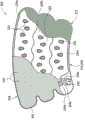
| Opening shape | The open area of each opening | The opening number putting | The open area of cover |
| 0529 ellipse | 0.81 | 23 | 6.7% |
| 0529 little water droplet | 0.27 | 27 | 2.6% |
| 0529 medium water droplet | 0.61 | 27 | 5.9% |
| 0529 large water droplet | 1.08 | 20 | 7.7% |
| 9529SCD? | 0 | 0 | 0.0% |
| 0592 circle | 0.81 | 23 | 6.7% |


Claims (20)
Applications Claiming Priority (3)
| Application Number | Priority Date | Filing Date | Title |
|---|---|---|---|
| US11/733,084 | 2007-04-09 | ||
| US11/733,084US8128584B2 (en) | 2007-04-09 | 2007-04-09 | Compression device with S-shaped bladder |
| CN200810090990.7ACN101292921B (en) | 2007-04-09 | 2008-04-08 | Compression device with S-shaped bladder |
Related Parent Applications (1)
| Application Number | Title | Priority Date | Filing Date |
|---|---|---|---|
| CN200810090990.7ADivisionCN101292921B (en) | 2007-04-09 | 2008-04-08 | Compression device with S-shaped bladder |
Publications (2)
| Publication Number | Publication Date |
|---|---|
| CN103550049Atrue CN103550049A (en) | 2014-02-05 |
| CN103550049B CN103550049B (en) | 2015-10-14 |
Family
ID=39462388
Family Applications (2)
| Application Number | Title | Priority Date | Filing Date |
|---|---|---|---|
| CN201310385868.3AExpired - Fee RelatedCN103550049B (en) | 2007-04-09 | 2008-04-08 | With the pressue device of the capsule of S shape |
| CN200810090990.7AExpired - Fee RelatedCN101292921B (en) | 2007-04-09 | 2008-04-08 | Compression device with S-shaped bladder |
Family Applications After (1)
| Application Number | Title | Priority Date | Filing Date |
|---|---|---|---|
| CN200810090990.7AExpired - Fee RelatedCN101292921B (en) | 2007-04-09 | 2008-04-08 | Compression device with S-shaped bladder |
Country Status (6)
| Country | Link |
|---|---|
| US (2) | US8128584B2 (en) |
| EP (1) | EP1980230A1 (en) |
| JP (2) | JP5236340B2 (en) |
| CN (2) | CN103550049B (en) |
| AU (1) | AU2008201503B2 (en) |
| CA (1) | CA2626963C (en) |
Cited By (1)
| Publication number | Priority date | Publication date | Assignee | Title |
|---|---|---|---|---|
| CN104739563A (en)* | 2015-04-17 | 2015-07-01 | 吕宏升 | Circular pressurization lower limb traction belt with cold compress function |
Families Citing this family (48)
| Publication number | Priority date | Publication date | Assignee | Title |
|---|---|---|---|---|
| US7871387B2 (en) | 2004-02-23 | 2011-01-18 | Tyco Healthcare Group Lp | Compression sleeve convertible in length |
| GB0515294D0 (en) | 2005-07-26 | 2005-08-31 | Novamedix Distrib Ltd | Limited durability closure means for an inflatable medical garment |
| US8029451B2 (en) | 2005-12-12 | 2011-10-04 | Tyco Healthcare Group Lp | Compression sleeve having air conduits |
| US8016779B2 (en) | 2007-04-09 | 2011-09-13 | Tyco Healthcare Group Lp | Compression device having cooling capability |
| US8021388B2 (en) | 2007-04-09 | 2011-09-20 | Tyco Healthcare Group Lp | Compression device with improved moisture evaporation |
| US8034007B2 (en) | 2007-04-09 | 2011-10-11 | Tyco Healthcare Group Lp | Compression device with structural support features |
| US8128584B2 (en)* | 2007-04-09 | 2012-03-06 | Tyco Healthcare Group Lp | Compression device with S-shaped bladder |
| US8162861B2 (en) | 2007-04-09 | 2012-04-24 | Tyco Healthcare Group Lp | Compression device with strategic weld construction |
| US8016778B2 (en) | 2007-04-09 | 2011-09-13 | Tyco Healthcare Group Lp | Compression device with improved moisture evaporation |
| US8506508B2 (en) | 2007-04-09 | 2013-08-13 | Covidien Lp | Compression device having weld seam moisture transfer |
| US8070699B2 (en) | 2007-04-09 | 2011-12-06 | Tyco Healthcare Group Lp | Method of making compression sleeve with structural support features |
| US8029450B2 (en) | 2007-04-09 | 2011-10-04 | Tyco Healthcare Group Lp | Breathable compression device |
| US8109892B2 (en) | 2007-04-09 | 2012-02-07 | Tyco Healthcare Group Lp | Methods of making compression device with improved evaporation |
| USD608006S1 (en) | 2007-04-09 | 2010-01-12 | Tyco Healthcare Group Lp | Compression device |
| US8114117B2 (en)* | 2008-09-30 | 2012-02-14 | Tyco Healthcare Group Lp | Compression device with wear area |
| US9113894B2 (en)* | 2008-05-21 | 2015-08-25 | Robert J. Perry | Vein presentation enhancement device |
| US8235923B2 (en) | 2008-09-30 | 2012-08-07 | Tyco Healthcare Group Lp | Compression device with removable portion |
| FR2939642A1 (en)* | 2008-12-16 | 2010-06-18 | Sayed Nour | NON-INVASIVE PULSATILE CIRCULATORY ASSISTANCE DEVICE |
| US8652079B2 (en) | 2010-04-02 | 2014-02-18 | Covidien Lp | Compression garment having an extension |
| US8979915B2 (en) | 2010-04-19 | 2015-03-17 | Pulsar Scientific, LLC | Separable system for applying compression and thermal treatment |
| US10751221B2 (en) | 2010-09-14 | 2020-08-25 | Kpr U.S., Llc | Compression sleeve with improved position retention |
| US8398572B2 (en)* | 2010-09-21 | 2013-03-19 | Covidien Lp | Bladder tube connection |
| US20120083712A1 (en)* | 2010-09-30 | 2012-04-05 | Tyco Healthcare Group Lp | Monitoring Compliance Using Venous Refill Detection |
| US8973162B1 (en)* | 2011-09-23 | 2015-03-10 | Joel H. Bretan | Assistive and protective garments |
| US20130085430A1 (en)* | 2011-09-30 | 2013-04-04 | Tyco Healthcare Group Lp. | Compression sleeve |
| US9205021B2 (en)* | 2012-06-18 | 2015-12-08 | Covidien Lp | Compression system with vent cooling feature |
| GB201219496D0 (en)* | 2012-10-30 | 2012-12-12 | Huntleigh Technology Ltd | Pressure cuff or garment |
| US9402779B2 (en) | 2013-03-11 | 2016-08-02 | Covidien Lp | Compression garment with perspiration relief |
| US9936751B1 (en) | 2013-03-14 | 2018-04-10 | Francesco Mignone | Towel/absorptive arm sleeve and means of hands free toweling |
| US9931269B2 (en) | 2013-03-15 | 2018-04-03 | Compression Therapy Concepts, Inc. | Air pump for use in intermittent pneumatic compression therapy having a digital display |
| US9713563B2 (en) | 2013-03-15 | 2017-07-25 | Compression Therapy Concepts, Inc. | Micro bleed hole connector for use in intermittent pneumatic compression devices |
| US9839573B2 (en) | 2013-03-15 | 2017-12-12 | Compression Therapy Concepts, Inc. | Compact mini air pump for use in intermittent pneumatic compression therapy |
| US9700481B2 (en) | 2013-03-15 | 2017-07-11 | Compression Therapy Concepts, Inc. | Deep vein thrombosis prevention garment having an expandable bladder |
| US9668932B2 (en) | 2013-03-15 | 2017-06-06 | Compression Therapy Concepts, Inc. | Portable micro air pump for use in intermittent pneumatic compression therapy |
| US9707125B2 (en)* | 2013-05-08 | 2017-07-18 | Beth Shannon Gomez | Ice wrap |
| US20150094629A1 (en)* | 2013-09-27 | 2015-04-02 | Covidien Lp | Compression garment controlling |
| US10646232B2 (en) | 2014-07-25 | 2020-05-12 | Western Clinical Engineering Ltd. | Tourniquet system for personalized restriction of blood flow |
| DE102014226841A1 (en)* | 2014-12-22 | 2016-06-23 | Bauerfeind Ag | pelotte |
| JP6714700B2 (en)* | 2015-07-13 | 2020-06-24 | コンメッド コーポレイション | Surgical suction device using positive pressure gas |
| WO2017062507A1 (en) | 2015-10-05 | 2017-04-13 | Tactile Systems Technology, Inc. | Adjustable compression garment |
| CN113456450B (en) | 2015-10-09 | 2025-01-07 | Kpr美国有限责任公司 | Compression Garment Compliance |
| US10076462B2 (en) | 2016-04-27 | 2018-09-18 | Radial Medical, Inc. | Adaptive compression therapy systems and methods |
| EP3571018B1 (en) | 2017-01-19 | 2024-10-02 | Vanderbilt University | Wearable assistance devices and methods of operation |
| CN107647957A (en)* | 2017-10-25 | 2018-02-02 | 厦门锦裕龙智能科技有限公司 | A kind of gasbag-type pressure system and the medical binding device with the system |
| DE102018102107A1 (en)* | 2018-01-31 | 2019-08-01 | ReActive Robotics GmbH | Cuff for receiving at least a part of an outer limb of a person |
| AU2020282797B2 (en) | 2019-05-28 | 2025-03-06 | Vanderbilt University | Moment arm extension system for exosuit |
| CN113274267B (en)* | 2021-05-28 | 2023-06-02 | 汪勇波 | A multi-chamber airbag, multi-mode control system and method for a brace |
| AU2023259619A1 (en)* | 2022-04-26 | 2024-11-07 | Vanderbilt University | An interface for a wearable assistance device |
Citations (6)
| Publication number | Priority date | Publication date | Assignee | Title |
|---|---|---|---|---|
| US2676587A (en)* | 1953-01-28 | 1954-04-27 | Laurence E Corcoran | Masklike device for toning and reinvigorating facial muscles and tissues |
| CN1009155B (en)* | 1985-07-08 | 1990-08-15 | 珀根马基 | Device for massaging extremities such as legs |
| US5450858A (en)* | 1993-02-02 | 1995-09-19 | Zablotsky; Theodore J. | Lumbosacral belt |
| WO2003007855A1 (en)* | 2001-07-20 | 2003-01-30 | Huntleigh Technology Plc | An inflatable apparatus |
| US20050187503A1 (en)* | 2004-02-23 | 2005-08-25 | Elise Tordella | Compression apparatus |
| US20060010574A1 (en)* | 2004-03-31 | 2006-01-19 | Bristol-Myers Squibb Company | Socks |
Family Cites Families (577)
| Publication number | Priority date | Publication date | Assignee | Title |
|---|---|---|---|---|
| US346979A (en) | 1886-08-10 | Rail-brace | ||
| US910689A (en)* | 1907-04-25 | 1909-01-26 | James M Kelly | Pneumatic pad for harness. |
| US908959A (en) | 1908-03-26 | 1909-01-05 | Charles Matthew Cooke | Bandage-support. |
| US1510482A (en) | 1923-08-02 | 1924-10-07 | Homer D Kramer | Sweatband for hats |
| US1608239A (en) | 1925-12-09 | 1926-11-23 | Rosett Joshua | Therapeutic device |
| US2199408A (en) | 1937-09-27 | 1940-05-07 | Liberte Elie J La | Registering tourniquet applicable for the determination of blood pressures |
| US2489388A (en) | 1947-03-19 | 1949-11-29 | Julius W Rubin | Foundation garment |
| US2533504A (en) | 1948-04-19 | 1950-12-12 | Philip Sampson J | Therapeutic apparatus |
| US2638915A (en) | 1950-12-13 | 1953-05-19 | Mbg Corp | Fluid coupling |
| US2694395A (en) | 1951-05-10 | 1954-11-16 | William J Brown | Pneumatic pressure garment |
| US2896612A (en) | 1956-06-28 | 1959-07-28 | Rolland H Bates | Physical therapeutic apparatus |
| US2880721A (en) | 1958-02-05 | 1959-04-07 | Laurence E Corcoran | Hand or foot carried pulsating massaging device |
| US2998817A (en) | 1959-08-07 | 1961-09-05 | Gary Armstrong Stebbins | Inflatable massaging and cooling mattress |
| US3164152A (en) | 1962-02-05 | 1965-01-05 | Nicoll Esmond D Vere | Inflatable splint |
| US3245405A (en) | 1962-11-26 | 1966-04-12 | William J Gardner | Inflatable therapeutic device and method of making same |
| US3288132A (en) | 1963-11-01 | 1966-11-29 | Anthony Myron L | Bladder structures useful in therapeutic treatment |
| US3351055A (en) | 1963-11-26 | 1967-11-07 | Jobst Institute | Pressure bandage-splint and method of forming same |
| US3504675A (en) | 1965-12-10 | 1970-04-07 | William A Bishop Jr | Disposable surgical tourniquet |
| US3473527A (en) | 1967-02-14 | 1969-10-21 | Irving Spiro | Orthopedic knee support |
| US3454010A (en) | 1967-05-08 | 1969-07-08 | Robert W Lilligren | Surgical bandage,constrictive device,and inflatable means |
| US3469769A (en) | 1967-10-09 | 1969-09-30 | Lion Packaging Products Co Inc | Interconnected bags having closure flaps and bottom gussets |
| US3568227A (en) | 1968-04-10 | 1971-03-09 | Philips Maine Corp | Inflatable cushion and apparatus for making same |
| US3561435A (en) | 1968-11-15 | 1971-02-09 | Dev Inc | Combined splint and coolant container |
| US3606880A (en) | 1969-04-18 | 1971-09-21 | Benjamin C Ogle Jr | Blood pressure cuff |
| US3701173A (en) | 1970-05-22 | 1972-10-31 | John K Whitney | Inflatable body support |
| US3638334A (en) | 1970-07-28 | 1972-02-01 | Ethel M Malikowski | Training garment |
| FR2109187A5 (en) | 1970-10-06 | 1972-05-26 | Ieram Sarl | |
| US3728875A (en) | 1971-01-07 | 1973-04-24 | Kendall & Co | Stocking with soft inner thigh area |
| DE7120141U (en) | 1971-02-01 | 1972-11-02 | Siemens Ag | BLOOD PRESSURE CUFF |
| US3770040A (en) | 1971-09-15 | 1973-11-06 | De Cicco M Augusta | Tire with safety indicator means |
| US3868952A (en) | 1971-12-14 | 1975-03-04 | Aerazur Constr Aeronaut | Inflatable shaped structures |
| US3771519A (en) | 1972-03-20 | 1973-11-13 | P Haake | Orthopedic suspension |
| US3824492A (en) | 1972-06-22 | 1974-07-16 | United Aircraft Corp | Solid state single frequency laser |
| US3906937A (en) | 1972-10-25 | 1975-09-23 | Para Medical Instr Corp | Blood pressure cuff and bladder and apparatus embodying the same |
| US3826249A (en) | 1973-01-30 | 1974-07-30 | A Lee | Leg constricting apparatus |
| US3878839A (en) | 1973-02-15 | 1975-04-22 | Hemodyne Inc | Cardiac assist apparatus |
| US3824992A (en) | 1973-03-16 | 1974-07-23 | Clinical Technology Inc | Pressure garment |
| US3877426A (en) | 1973-03-27 | 1975-04-15 | Robert P Nirschl | Muscular support |
| US3862629A (en) | 1973-05-02 | 1975-01-28 | Nicholas R Rotta | Fluid pressure controlled means for producing peristaltic operation of series-connected inflatable chambers in therapeutic devices, pumps and the like |
| US3899210A (en) | 1973-06-01 | 1975-08-12 | Lederman S Inc | Bean-bag chair |
| US3955565A (en) | 1973-12-05 | 1976-05-11 | Johnson Jr Glenn W | Orthopedic apparatus |
| US3920006A (en) | 1974-01-02 | 1975-11-18 | Roy Lapidus Inc | Inflatable device for healing of tissue |
| US4066084A (en) | 1974-01-14 | 1978-01-03 | Hans Tillander | Blood emptying device |
| US3901221A (en) | 1974-04-08 | 1975-08-26 | Clinical Technology Internatio | Pressure cycle for stimulating blood circulation in the limbs |
| IT1038112B (en) | 1975-05-13 | 1979-11-20 | Sir Soc Italiana Resine Spa | PROCEDURE FOR CONVERSION, TRANSPORTATION AND USE OF ENERGY |
| US4013069A (en) | 1975-10-28 | 1977-03-22 | The Kendall Company | Sequential intermittent compression device |
| US4029087A (en) | 1975-10-28 | 1977-06-14 | The Kendall Company | Extremity compression device |
| US4030488A (en) | 1975-10-28 | 1977-06-21 | The Kendall Company | Intermittent compression device |
| US4054129A (en) | 1976-03-29 | 1977-10-18 | Alba-Waldensian, Inc. | System for applying pulsating pressure to the body |
| US4091804A (en) | 1976-12-10 | 1978-05-30 | The Kendall Company | Compression sleeve |
| US4076022A (en) | 1976-12-20 | 1978-02-28 | James Walker | Therapeutic foot and leg protector |
| JPS53115424A (en) | 1977-03-17 | 1978-10-07 | Nippon Soken Inc | Ignition device for rotary piston engine |
| US4453538A (en) | 1977-04-07 | 1984-06-12 | Whitney John K | Medical apparatus |
| US4294240A (en) | 1977-07-14 | 1981-10-13 | Minnesota Mining And Manufacturing Company | Perforated closed cell padding material |
| US4153050A (en) | 1977-07-29 | 1979-05-08 | Alba-Waldensian, Incorporated | Pulsatile stocking and bladder therefor |
| US4156425A (en) | 1977-08-10 | 1979-05-29 | The Kendall Company | Protective compression sleeve |
| US4146021A (en) | 1977-08-24 | 1979-03-27 | Brosseau Janet V | Orthopedic traction harness |
| US4351872A (en) | 1977-08-24 | 1982-09-28 | Harvey G. Lowhurst | Unidirectional stretch mesh laminate and method |
| US4149529A (en) | 1977-09-16 | 1979-04-17 | Jobst Institute, Inc. | Portable thermo-hydraulic physiotherapy device |
| US4149541A (en)* | 1977-10-06 | 1979-04-17 | Moore-Perk Corporation | Fluid circulating pad |
| US4206751A (en) | 1978-03-31 | 1980-06-10 | Minnesota Mining And Manufacturing Company | Intermittent compression device |
| US4201203A (en) | 1978-06-26 | 1980-05-06 | Surgical Appliance Industries, Inc. | Knee brace |
| US4207875A (en) | 1979-01-12 | 1980-06-17 | The Kendall Company | Compression device with knee accommodating sleeve |
| US4202325A (en) | 1979-01-12 | 1980-05-13 | The Kendall Company | Compression device with improved fastening sleeve |
| US4207876A (en) | 1979-01-12 | 1980-06-17 | The Kendall Company | Compression device with ventilated sleeve |
| US4198961A (en) | 1979-01-12 | 1980-04-22 | The Kendall Company | Compression device with sleeve retained conduits |
| US4219892A (en)* | 1979-02-05 | 1980-09-02 | Rigdon Robert W | Knee brace for preventing injury from lateral impact |
| AU5507380A (en) | 1979-02-14 | 1980-08-21 | Kalmar, I. | Plaster cast |
| US4267611A (en) | 1979-03-08 | 1981-05-19 | Arnold Agulnick | Inflatable massaging and cooling mattress |
| US4253449A (en) | 1979-08-09 | 1981-03-03 | The Kendall Company | Compression device with connection system |
| US4270527A (en) | 1979-08-09 | 1981-06-02 | Armstrong Industries, Inc. | Inflatable trouser for medical use |
| US4437269A (en) | 1979-08-17 | 1984-03-20 | S.I.A.C.O. Limited | Abrasive and polishing sheets |
| GB2061086A (en) | 1979-10-17 | 1981-05-13 | Rowell R F | Improvements in brassiere wires |
| US4311135A (en) | 1979-10-29 | 1982-01-19 | Brueckner Gerald G | Apparatus to assist leg venous and skin circulation |
| US4300245A (en) | 1979-12-10 | 1981-11-17 | Queen's University At Kingston | Pneumatic leg |
| US4320746A (en) | 1979-12-07 | 1982-03-23 | The Kendall Company | Compression device with improved pressure control |
| US4363125A (en) | 1979-12-26 | 1982-12-07 | International Business Machines Corporation | Memory readback check method and apparatus |
| US4280485A (en) | 1980-04-11 | 1981-07-28 | The Kendall Company | Compression device with simulator |
| US4375217A (en) | 1980-06-04 | 1983-03-01 | The Kendall Company | Compression device with pressure determination |
| US4355632A (en) | 1980-08-06 | 1982-10-26 | Jobst Institute, Inc. | Anti-shock pressure garment |
| JPS596654B2 (en) | 1980-08-25 | 1984-02-14 | 松下電工株式会社 | electronic blood pressure monitor |
| US4372297A (en) | 1980-11-28 | 1983-02-08 | The Kendall Company | Compression device |
| US4379217A (en) | 1981-02-05 | 1983-04-05 | Youmans Grace A | Method and means of melting frozen material on terrain or water surfaces |
| US4408599A (en) | 1981-08-03 | 1983-10-11 | Jobst Institute, Inc. | Apparatus for pneumatically controlling a dynamic pressure wave device |
| IL63574A (en) | 1981-08-14 | 1985-07-31 | Mego Afek | Massaging sleeve for body limbs |
| US4402312A (en) | 1981-08-21 | 1983-09-06 | The Kendall Company | Compression device |
| US4442834A (en) | 1981-10-02 | 1984-04-17 | Jobst Institute, Inc. | Pneumatic splint |
| US4445505A (en) | 1981-12-28 | 1984-05-01 | Donald Labour | Knee brace for preventing lateral displacement of the patella |
| IT1164326B (en) | 1982-08-11 | 1987-04-08 | Man Design Co | GLOVES FOR THE RECOVERY OF THE FUNCTIONS OF THE CARPAL JOINT, HANDS AND FINGERS |
| US4624248A (en) | 1983-02-07 | 1986-11-25 | David Clark Company Incorporated | Transparent pressure garment |
| US4531516A (en) | 1983-02-07 | 1985-07-30 | David Clark Company Incorporated | Transparent pressure garment |
| US4547919A (en) | 1983-02-17 | 1985-10-22 | Cheng Chung Wang | Inflatable article with reforming and reinforcing structure |
| US4696289C1 (en) | 1983-06-22 | 2002-09-03 | Novamedix Distrib Ltd | Method of stimulating the venous-pump mechanism of the foot and for enhancement of arterial flow to the foot |
| US4614180A (en) | 1984-06-18 | 1986-09-30 | Electro-Biology, Inc. | Medical appliance |
| ATE49114T1 (en) | 1983-06-22 | 1990-01-15 | Novamedix Ltd | MEDICAL DEVICE FOR PUMPING THE SOLE OF THE FOOT. |
| US4614179A (en) | 1985-08-08 | 1986-09-30 | Electro-Biology, Inc. | Medical appliance |
| US4547906A (en)* | 1983-06-27 | 1985-10-22 | Kanebo, Ltd. | Heat retaining article |
| US4552821A (en) | 1983-06-30 | 1985-11-12 | Duracell Inc. | Sealed nickel-zinc battery |
| US4657003A (en) | 1983-10-03 | 1987-04-14 | Cramer Products, Inc. | Immobilizer device |
| JPS6083621U (en)* | 1983-11-15 | 1985-06-10 | 松下電工株式会社 | air mat |
| US4580816A (en) | 1984-01-25 | 1986-04-08 | E. R. Squibb & Sons, Inc. | Quick disconnect tube coupling |
| GB8402351D0 (en) | 1984-01-30 | 1984-02-29 | Saggers M J | Inflatable garment |
| US4593692A (en) | 1984-06-04 | 1986-06-10 | Medasonics, Inc. | Plethysmograph cuff bladder |
| US4721101C1 (en) | 1984-06-18 | 2002-06-18 | Novamedix Distrib Ltd | Medical appliance for artificial actuation of the venous-pump mechanism in a human foot and for enhancement of arterial flow |
| US4597384A (en)* | 1984-06-29 | 1986-07-01 | Gaymar Industries, Inc. | Sequential compression sleeve |
| DE3433795A1 (en) | 1984-09-14 | 1986-03-27 | Penny S. Tempe Ariz. Cronin | SUPPORT GLOVE FOR SUPPORT OR TREATING A SICK, IN PARTICULAR ARTHRITIC HAND |
| US4624244A (en) | 1984-10-15 | 1986-11-25 | Taheri Syde A | Device for aiding cardiocepital venous flow from the foot and leg of a patient |
| US4706673A (en) | 1984-12-31 | 1987-11-17 | Dive N'surf, Inc. | Liquid pack and retention device therefor |
| US4650452A (en) | 1985-04-29 | 1987-03-17 | Squibb Corporation | Method for joining a tube to a collection pouch |
| US4682588A (en) | 1985-05-07 | 1987-07-28 | Pneumedic Corp. | Compound force therapeutic corset |
| US4832010A (en) | 1985-06-11 | 1989-05-23 | Max Lerman | Orthopedic supports and material for making same |
| GB2178663B (en) | 1985-06-27 | 1989-02-01 | Ambroplastics Ltd | Inflatable bag for use as a splint |
| US4702232A (en) | 1985-10-15 | 1987-10-27 | Electro-Biology, Inc. | Method and apparatus for inducing venous-return flow |
| DE3537846C1 (en) | 1985-10-24 | 1987-05-07 | Daimler Benz Ag | Adjustable backrest for car seats |
| GB8528590D0 (en) | 1985-11-20 | 1985-12-24 | Smith & Nephew Ass | Pressure sore device |
| US4809684A (en) | 1985-12-16 | 1989-03-07 | Novamedix Limited | Pressure appliance for the hand for aiding circulation |
| US4846160A (en) | 1985-12-16 | 1989-07-11 | Novamedix Limited | Method of promoting circulation in the hand |
| US4730606A (en) | 1986-01-22 | 1988-03-15 | Kinetic Concepts, Inc. | Apparatus for applying traction during oscillatory therapy |
| SE8603115L (en) | 1986-07-15 | 1988-01-16 | Per Danielsson | METHOD AND APPARATUS FOR BLOOD PRESSURE SAFETY |
| US4836194A (en) | 1986-08-29 | 1989-06-06 | Safeguard Industrial Corporation | Therapeutic lumbosacral appliance |
| US4703750A (en) | 1986-08-29 | 1987-11-03 | Sebastian Peter R | Therapeutic lumbosacral appliance |
| US4938207A (en) | 1986-10-20 | 1990-07-03 | Alexander C. Vargo | Knee brace having plurality of fluid filled chambers surrounding knee |
| US4872448A (en) | 1986-10-22 | 1989-10-10 | Johnson Jr Glenn W | Knee brace having adjustable inflatable U-shaped air cell |
| US5226564A (en) | 1986-11-28 | 1993-07-13 | E. R. Squibb & Sons, Inc. | Manufacture of bags |
| US4876788A (en) | 1986-11-28 | 1989-10-31 | E. R. Squibb And Sons, Inc. | Method of making a leakproof connection about the outlet tube of a liquid containment bag |
| USD302301S (en) | 1987-01-15 | 1989-07-18 | Aspen Laboratories, Inc. | Tourniquet cuff |
| JPH0710275B2 (en) | 1987-03-04 | 1995-02-08 | 株式会社新素材総合研究所 | Medical container and method of manufacturing the same |
| US4869265A (en) | 1987-04-03 | 1989-09-26 | Western Clinical Engineering Ltd. | Biomedical pressure transducer |
| US5181522A (en) | 1987-04-03 | 1993-01-26 | Abatis Medical Technologies Limited | Tourniquet for sensing and regulation of applied pressure |
| US5048536A (en) | 1987-04-03 | 1991-09-17 | Mcewen James A | Tourniquet for regulating applied pressures |
| US4773397A (en) | 1987-06-22 | 1988-09-27 | Wright Linear Pump, Inc. | Apparatus for promoting flow of a body fluid within a human limb |
| US4846189A (en) | 1987-06-29 | 1989-07-11 | Shuxing Sun | Noncontactive arterial blood pressure monitor and measuring method |
| GB2207862B (en) | 1987-08-13 | 1990-07-18 | Btr Plc | Pressurising system |
| US5022387A (en) | 1987-09-08 | 1991-06-11 | The Kendall Company | Antiembolism stocking used in combination with an intermittent pneumatic compression device |
| US4827912A (en) | 1987-09-18 | 1989-05-09 | The Kendall Company | Multi-chamber porting device |
| DE3804016A1 (en) | 1988-02-10 | 1989-08-24 | Beiersdorf Ag | DEVICE FOR THE TREATMENT OF HUMAN EXTREMITIES BY INTERMITTING COMPRESSION |
| DK159193C (en) | 1988-06-07 | 1991-03-25 | S O Siemssen | CONTRACTUAL AND COMPRESSION STRIPS CONSISTING OF MORE SUCH ITEMS FOR PERISTALTIC TREATMENT OF PATIENTS EXTREMITIES |
| US4886053A (en) | 1988-07-21 | 1989-12-12 | Deroyal Industries, Inc. | Stay for orthopedic appliance for the knee |
| US4913136A (en) | 1988-08-02 | 1990-04-03 | Chong Andrew K | Harness for the treatment of congenital hip dislocation in infants |
| US4960115A (en) | 1988-08-05 | 1990-10-02 | Peter Ranciato | Body support apparatus |
| US4964402A (en) | 1988-08-17 | 1990-10-23 | Royce Medical Company | Orthopedic device having gel pad with phase change material |
| US4945571A (en) | 1988-09-26 | 1990-08-07 | In Motion, Inc. | Liquid-cushioned outerwear |
| US4957105A (en) | 1988-10-04 | 1990-09-18 | Kurth Paul A | Femoral compression device for post-catheterization hemostasis |
| US5637106A (en) | 1988-11-16 | 1997-06-10 | Carol M. Stocking | Absorbent product for personal use |
| US5062414A (en) | 1989-02-08 | 1991-11-05 | Royce Medical Company | Simplified orthopaedic back support |
| US5031604A (en) | 1989-04-12 | 1991-07-16 | The Kendall Company | Device for applying compressive pressures to a patient's limb |
| US5007411A (en) | 1989-04-12 | 1991-04-16 | The Kendall Company | Device for applying compressive pressures against a patient's limb |
| US4938208A (en) | 1989-03-16 | 1990-07-03 | The Kendall Company | Full length compressible sleeve |
| CA2012140C (en) | 1989-03-17 | 1999-01-26 | Daniel R. Potter | Athletic shoe with pressurized ankle collar |
| US4898160A (en) | 1989-03-24 | 1990-02-06 | Alliance Group Inc. | Surgical cast venting device |
| US5014681A (en) | 1989-05-05 | 1991-05-14 | Mego Afek Industrial Measuring Instruments | Method and apparatus for applying intermittent compression to a body part |
| US5052377A (en) | 1989-06-01 | 1991-10-01 | Jean Frajdenrajch | Apparatus for massaging the body by cyclic pressure, and constituent means |
| US4883073A (en) | 1989-07-03 | 1989-11-28 | Farooq Aziz | Remedial device for treatment of carpal tunnel syndrome |
| US5080951A (en) | 1989-08-03 | 1992-01-14 | Guthrie David W | Nonwoven fabric |
| US4989273A (en) | 1989-10-23 | 1991-02-05 | Cromartie Hendrick L | Swimwear stay for water skiers |
| GB8926920D0 (en) | 1989-11-29 | 1990-01-17 | Barry Thomas | Inflatable body supports and splints |
| US5069219A (en) | 1989-12-20 | 1991-12-03 | Spacelabs, Inc. | Self snugging universal blood pressure cuff |
| USD332495S (en) | 1990-01-09 | 1993-01-12 | Mae Lake | Pelvic lap restraint |
| US4979953A (en) | 1990-02-16 | 1990-12-25 | Instrumed, Inc. | Medical disposable inflatable tourniquet cuff |
| US5172689A (en)* | 1990-03-01 | 1992-12-22 | Wright Christopher A | Cryogenic sleeve for providing therapeutic compression |
| US5156629A (en) | 1990-03-15 | 1992-10-20 | Shane Mark D | Pneumatic prosthetic insert |
| US5193549A (en) | 1990-07-11 | 1993-03-16 | Biomedical Dynamics Corporation | Inflatable cuff |
| US5139475A (en) | 1990-08-14 | 1992-08-18 | Francis Robicsek | Medical appliance for treating venous insufficiency |
| US5277697A (en) | 1990-08-17 | 1994-01-11 | Hanger Orthopedic Group, Inc. | Patella-femoral brace |
| US5168576A (en) | 1990-10-03 | 1992-12-08 | Krent Edward D | Body protective device |
| US5146932A (en) | 1990-11-01 | 1992-09-15 | Mccabe Francis J | Elastic counterpressure garment |
| US5259397A (en) | 1990-11-01 | 1993-11-09 | Mccabe Francis J | Foam counterpressure garment |
| US5263473A (en) | 1990-11-05 | 1993-11-23 | The Kendall Company | Compression device for the limb |
| US5117812A (en) | 1990-11-05 | 1992-06-02 | The Kendall Company | Segmented compression device for the limb |
| US5120300A (en) | 1990-11-16 | 1992-06-09 | Shaw Frank D | Compression band for quick application |
| US5109832A (en) | 1990-12-07 | 1992-05-05 | Proctor Richard D J | Method of and apparatus for producing alternating pressure in a therapeutic device |
| US5230335A (en) | 1991-01-23 | 1993-07-27 | Aircast, Inc. | Thermal compress system |
| US5314455A (en) | 1991-01-23 | 1994-05-24 | Aircast, Inc. | Thermal compress system |
| US5466250A (en) | 1991-01-23 | 1995-11-14 | Aircast, Inc. | Automatic fluid compress and circulating system |
| US5135473A (en) | 1991-01-31 | 1992-08-04 | Marcia Epler | Achilles tendon wrap |
| US5139476A (en) | 1991-04-26 | 1992-08-18 | Camp International, Inc. | Orthotic knee wrap |
| US5139479A (en) | 1991-04-26 | 1992-08-18 | Camp International, Inc. | Ankle sleeve |
| US5211162A (en) | 1991-07-09 | 1993-05-18 | Pneu-Mobility, Inc. | Apparatus and method for massaging the back utilizing pneumatic cushions |
| US5226245A (en) | 1991-09-20 | 1993-07-13 | Lamont William D | Protective boot structure |
| US5989204A (en) | 1991-09-27 | 1999-11-23 | Kinetic Concepts, Inc. | Foot-mounted venous compression device |
| US5741295A (en) | 1991-09-30 | 1998-04-21 | James A. McEwen | Overlapping tourniquet cuff system |
| US5649954A (en) | 1991-09-30 | 1997-07-22 | Mcewen; James A. | Tourniquet cuff system |
| US5312431A (en) | 1991-09-30 | 1994-05-17 | Abatis Medical Technologies Limited | Occlusive cuff |
| US5221252A (en) | 1991-10-15 | 1993-06-22 | Tru-Fit Marketing Corp. | Adjustable knee support |
| US5277695A (en) | 1991-11-08 | 1994-01-11 | Aircast, Inc. | Adjustable ankle compress |
| US5186163A (en) | 1991-11-25 | 1993-02-16 | The Kendall Company | Compression device |
| US5261871A (en) | 1991-12-12 | 1993-11-16 | Greenfield Raphael L | Orthopedic device |
| US6468237B1 (en) | 1991-12-17 | 2002-10-22 | Kinetic Concepts, Inc. | Pneumatic pump, housing and methods for medical purposes |
| DE69232191T2 (en) | 1991-12-17 | 2002-08-29 | Kinetic Concepts, Inc. | PNEUMATIC COMPRESSION DEVICE FOR USE IN THE MEDICAL AREA |
| US5158541A (en) | 1992-01-23 | 1992-10-27 | Mccurley Arlene B | Mastectomy compression surgical brassiere |
| US5245990A (en)* | 1992-02-14 | 1993-09-21 | Millo Bertinin | Apparatus for enhancing venous circulation and for massage |
| US5352189A (en) | 1992-02-19 | 1994-10-04 | Tecnol Medical Products, Inc. | Ankle brace walker |
| US5288286A (en)* | 1992-02-25 | 1994-02-22 | Davis Albert D | Adjustable pressure cast for orthopedic injuries |
| US5342285A (en) | 1992-06-19 | 1994-08-30 | The Kendall Company | Adapter for devices for applying compressive pressure to the limbs |
| US5462517A (en) | 1992-06-26 | 1995-10-31 | D'mannco, Inc. | Knee brace having an inflatable bladder support |
| US5385538A (en) | 1992-06-26 | 1995-01-31 | D'mannco, Inc. | Knee brace having an inflatable bladder support |
| US5451201A (en) | 1992-09-24 | 1995-09-19 | Innovative Footwear Corporation | Joint support apparatus |
| GB2271060B (en) | 1992-10-01 | 1996-04-03 | Huntleigh Technology Plc | An inflatable garment |
| WO1994009732A1 (en) | 1992-10-29 | 1994-05-11 | Aircast, Inc. | Automatic fluid circulating system and method |
| DE4237389A1 (en) | 1992-11-05 | 1994-05-11 | Beiersdorf Ag | Elastic tubular bandage for knee joint |
| US5391141A (en) | 1992-11-10 | 1995-02-21 | Hamilton; Josef N. | Adjustable size and variable pressure regulated medical binder used by a patient after her or his body surgery |
| US5584798A (en) | 1992-11-23 | 1996-12-17 | Novamedix Limited | Medical inflatable cuff appliance |
| US5669872A (en) | 1992-11-23 | 1997-09-23 | Novamedix Limited | Method for focused delivery of venous flow for artificial impluse compression of an anatomical foot pump |
| US5419757A (en) | 1992-12-28 | 1995-05-30 | Daneshvar; Yousef | Support containing shaped balloons |
| GB9300847D0 (en) | 1993-01-18 | 1993-03-10 | Gardner Arthur M N | Medical appliance |
| US5334135A (en) | 1993-02-16 | 1994-08-02 | Grim Tracy E | Formed resilient orthopaedic support |
| JPH0670729U (en)* | 1993-03-24 | 1994-10-04 | 株式会社ケープ | Health air mat |
| US5354260A (en) | 1993-05-13 | 1994-10-11 | Novamedix, Ltd. | Slipper with an inflatable foot pump |
| US5383919A (en) | 1993-05-18 | 1995-01-24 | Danninger Medical Technology, Inc. | Thermal therapy pad |
| US5588956A (en) | 1993-06-09 | 1996-12-31 | Billotti; Joseph D. | Method for supporting body joints and brace therefor |
| US5378224A (en) | 1993-06-09 | 1995-01-03 | Billotti; Joseph D. | Method for supporting body joints and brace therefor |
| US5443440A (en) | 1993-06-11 | 1995-08-22 | Ndm Acquisition Corp. | Medical pumping apparatus |
| US5769801A (en) | 1993-06-11 | 1998-06-23 | Ndm Acquisition Corp. | Medical pumping apparatus |
| US5389065A (en) | 1993-06-15 | 1995-02-14 | Aircast, Inc. | Ankle brace with ATF compression |
| US5437595A (en) | 1993-07-08 | 1995-08-01 | W. R. Grace & Co. | Method and apparatus for producing medical pouches |
| JP3553944B2 (en) | 1993-07-08 | 2004-08-11 | エアキャスト, インコーポレイテッド | Method and apparatus for providing therapeutic intermittent compression for reducing the risk of DVT |
| US5609570A (en) | 1993-07-12 | 1997-03-11 | Lamed, Inc. | Protective medical boot and orthotic splint |
| US5453081A (en) | 1993-07-12 | 1995-09-26 | Hansen; Craig N. | Pulsator |
| US5449379A (en)* | 1993-07-21 | 1995-09-12 | Alternative Compression Technologies, Inc. | Apparatus for applying a desired temperature and pressure to an injured area |
| US5383894A (en) | 1993-07-30 | 1995-01-24 | The Kendall Co. | Compression device having stepper motor controlled valves |
| US5449341A (en) | 1993-08-16 | 1995-09-12 | Becton, Dickinson And Company | Compression support braces |
| US5591337A (en) | 1993-09-14 | 1997-01-07 | Baxter International Inc. | Apparatus for filtering leukocytes from blood cells |
| US5406661A (en) | 1993-09-15 | 1995-04-18 | Reebok International Ltd. | Preloaded fluid bladder with integral pump |
| US5478119A (en) | 1993-09-16 | 1995-12-26 | The Kendall Company | Polarized manifold connection device |
| USD358216S (en) | 1993-09-16 | 1995-05-09 | The Kendall Company | Sleeve for applying compressive pressure to the leg |
| US5795312A (en) | 1993-09-27 | 1998-08-18 | The Kendall Company | Compression sleeve |
| GB9321602D0 (en) | 1993-10-20 | 1993-12-08 | Neoligaments Ltd | Controller |
| US5489259A (en) | 1993-10-27 | 1996-02-06 | Sundance Enterprises, Inc. | Pressure-normalizing single-chambered static pressure device for supporting and protecting a body extremity |
| US5413582A (en) | 1993-11-03 | 1995-05-09 | Electromedics, Inc. | Inflatable tourniquet cuff and method of making same |
| US5403265A (en) | 1993-11-03 | 1995-04-04 | Lunax Corporation | Pressure sock |
| US5458265A (en) | 1993-11-18 | 1995-10-17 | Levi Strauss & Co. | Automated garment finishing system |
| US5514155A (en) | 1993-12-14 | 1996-05-07 | Daneshvar; Yousef | Device for applying pressure to a person's groin |
| US5968072A (en) | 1993-12-20 | 1999-10-19 | Medical Wraps, Inc. | Method and apparatus for cold compression treatment of wounds |
| US5496262A (en) | 1994-01-06 | 1996-03-05 | Aircast, Inc. | Therapeutic intermittent compression system with inflatable compartments of differing pressure from a single source |
| US5437610A (en) | 1994-01-10 | 1995-08-01 | Spinal Cord Society | Extremity pump apparatus |
| US5425701A (en) | 1994-01-21 | 1995-06-20 | Minnesota Mining And Manufacturing Company | Orthopedic brace having width adjusting vamp |
| JPH07265354A (en) | 1994-03-30 | 1995-10-17 | Morito Kk | Knee supporter |
| US5588954A (en) | 1994-04-05 | 1996-12-31 | Beiersdorf-Jobst, Inc. | Connector for a gradient sequential compression system |
| USD376013S (en) | 1994-04-05 | 1996-11-26 | Beiersdorf-Jobst, Inc. | Compression sleeve for deep vein thrombosis |
| US5575762A (en) | 1994-04-05 | 1996-11-19 | Beiersdorf-Jobst, Inc. | Gradient sequential compression system and method for reducing the occurrence of deep vein thrombosis |
| WO1995026703A1 (en) | 1994-04-05 | 1995-10-12 | Beiersdorf-Jobst, Inc. | Compression sleeve for use with a gradient sequential compression system |
| US5470156A (en) | 1994-04-11 | 1995-11-28 | Reynolds Consumer Products, Inc. | Closure arrangement having a peelable seal |
| DE4412765C2 (en) | 1994-04-13 | 2001-09-20 | Zimmermann Sanitaets Und Ortho | Joint orthosis, in particular knee orthosis with fluid-stiffenable pockets |
| US5407421A (en) | 1994-05-18 | 1995-04-18 | Goldsmith; Seth | Compressive brace |
| US5823981A (en) | 1994-06-06 | 1998-10-20 | Royce Medical Company | Resilient orthopaedic support with independently stretchable layers |
| US5591200A (en) | 1994-06-17 | 1997-01-07 | World, Inc. | Method and apparatus for applying pressure to a body limb for treating edema |
| US5503620A (en) | 1994-07-01 | 1996-04-02 | Charm-Tex Inc. | Back support belt apparatus and method |
| US5554105A (en) | 1994-07-01 | 1996-09-10 | Generation Ii Orthotics, Inc | Patella stabilizer |
| US5664270A (en) | 1994-07-19 | 1997-09-09 | Kinetic Concepts, Inc. | Patient interface system |
| CA2153375C (en) | 1994-07-26 | 2000-09-12 | Arnold Tobler | Attachment of hook and loop fastener to a compression sleeve |
| US5511552A (en) | 1994-09-02 | 1996-04-30 | Cas Medical Systems, Inc. | Disposable blood pressure cuff |
| US5514081A (en) | 1994-10-07 | 1996-05-07 | D'mannco, Inc. | Elbow orthosis having an inflatable bladder support and method of use |
| EP0705543B1 (en) | 1994-10-07 | 1999-03-24 | Wacoal Corp. | Lower leg protection garment |
| US5876359A (en) | 1994-11-14 | 1999-03-02 | Bock; Malcolm G. | Sequential compression device controller |
| DE69637293T2 (en) | 1995-02-17 | 2008-08-07 | Reid, Tony, Santa Cruz | DEVICE FOR TREATING OILS |
| JP2605674B2 (en) | 1995-02-20 | 1997-04-30 | 日本電気株式会社 | Fine pattern forming method |
| US5746213A (en) | 1995-02-24 | 1998-05-05 | Marks; Lloyd A. | Adjustable blood pressure cuff and method of using same |
| US5769800A (en) | 1995-03-15 | 1998-06-23 | The Johns Hopkins University Inc. | Vest design for a cardiopulmonary resuscitation system |
| GB9507328D0 (en) | 1995-04-08 | 1995-05-31 | Novamedix Ltd | A medical device |
| US5728058A (en) | 1995-06-29 | 1998-03-17 | The Procter & Gamble Company | Elastic knee wrap |
| US5790998A (en) | 1995-08-03 | 1998-08-11 | Crescimbeni; Jayne A. | Leg positioning device |
| US5840049A (en) | 1995-09-07 | 1998-11-24 | Kinetic Concepts, Inc. | Medical pumping apparatus |
| DK0855888T3 (en) | 1995-10-03 | 2003-02-17 | Tru Fit Marketing Corp | Therapeutic elastic body support |
| US5833639A (en) | 1995-10-27 | 1998-11-10 | Johnson & Johnson Professional, Inc. | Short leg walker |
| US5695453A (en) | 1995-12-22 | 1997-12-09 | Deroyal Industries, Inc. | Limb immobilizer having reinforcing wire members embedded therin |
| SE506193C2 (en) | 1996-01-02 | 1997-11-17 | Aba Sweden Ab | Device for hose connections |
| US5626557A (en) | 1996-01-11 | 1997-05-06 | D'mannco, Inc | Knee brace having an inflatable bladder and exterior support element |
| US5674262A (en) | 1996-01-26 | 1997-10-07 | Kinetic Concepts, Inc. | Pneumatic compression and functional electric stimulation device and method using the same |
| US5728055A (en) | 1996-01-30 | 1998-03-17 | Fisher Scientific Company | Therapeutic lumbosacral appliance |
| IL117902A (en) | 1996-04-15 | 2000-12-06 | Mego Afek Ind Measuring Instr | Inflatable sleeve |
| US5717996A (en) | 1996-04-18 | 1998-02-17 | Feldmann; Dov | Shin and ankle protection device |
| GB9608231D0 (en) | 1996-04-20 | 1996-06-26 | Gilholm S P | Compression device |
| US5843007A (en) | 1996-04-29 | 1998-12-01 | Mcewen; James Allen | Apparatus and method for periodically applying a pressure waveform to a limb |
| US5653244A (en) | 1996-06-04 | 1997-08-05 | Circaid Medical Products, Inc. | Therapeutic compression garment |
| USD383547S (en) | 1996-06-04 | 1997-09-09 | Breg, Inc. | Cold therapy pad with mounting straps |
| US20010018564A1 (en) | 1996-06-07 | 2001-08-30 | Medical Dynamics (Israel) 1998 Ltd. | Medical apparatus for facilitating blood circulation in the lower limbs |
| IL120935A0 (en) | 1996-06-07 | 1997-09-30 | Bibi Roni | Medical apparatus for facilitating blood circulation in the lower limbs |
| US6319215B1 (en) | 1999-07-29 | 2001-11-20 | Medical Dynamics Usa, Llc | Medical device for applying cyclic therapeutic action to a subject's foot |
| SE511502C2 (en) | 1996-06-26 | 1999-10-11 | Irene Hoernberg | Pressure dressing for hip replacement surgery patients |
| CA2229846C (en) | 1996-07-03 | 2006-05-30 | Baxter International Inc. | Method of sealing a port tube in a container |
| US5891065A (en) | 1996-07-31 | 1999-04-06 | Spinal Cord Society | Mobile extremity pumping apparatus |
| US5966763A (en) | 1996-08-02 | 1999-10-19 | Hill-Rom, Inc. | Surface pad system for a surgical table |
| US5733304A (en) | 1996-08-21 | 1998-03-31 | Instrumed, Inc. | Disposable inflatable tourniquet cuff |
| US7288076B2 (en) | 1996-08-29 | 2007-10-30 | Ossur Hf | Self-equalizing resilient orthopaedic support |
| US6129688A (en) | 1996-09-06 | 2000-10-10 | Aci Medical | System for improving vascular blood flow |
| US6358219B1 (en) | 1996-09-06 | 2002-03-19 | Aci Medical | System and method of improving vascular blood flow |
| US6387065B1 (en) | 1996-09-30 | 2002-05-14 | Kinetic Concepts, Inc. | Remote controllable medical pumping apparatus |
| US5704999A (en) | 1996-10-04 | 1998-01-06 | The Goodyear Tire & Rubber Company | Pneumatic tire with rubber wear indicator between carcass plies |
| US6322530B1 (en) | 1996-11-08 | 2001-11-27 | Aircast, Inc. | Pneumatic Achilles wrap |
| US6129695A (en) | 1996-12-18 | 2000-10-10 | Peters; Rick | Athletic brace |
| DE19653257C2 (en) | 1996-12-20 | 2001-09-13 | Mannesmann Vdo Ag | Hose coupling provided for connecting a hose with a second component |
| US6048326A (en) | 1996-12-31 | 2000-04-11 | The Procter & Gamble Company | Disposable elastic thermal knee wrap |
| US6209159B1 (en) | 1997-01-10 | 2001-04-03 | Comfortex Health Care Surfaces | Pressure reducing cushion with selective pressure point relief |
| US5797851A (en) | 1997-02-18 | 1998-08-25 | Byrd; Timothy N. | Medical bladder cover |
| US6540707B1 (en) | 1997-03-24 | 2003-04-01 | Izex Technologies, Inc. | Orthoses |
| US5894682A (en) | 1997-04-08 | 1999-04-20 | Broz; Joseph S. | Shoe with built-in diagnostic indicator of biomechanical compatibility, wear patterns and functional life of shoe, and method of construction thereof |
| US6179796B1 (en) | 1997-04-11 | 2001-01-30 | Tactile Systems, Inc. | Lymphedema treatment system |
| US6860862B2 (en) | 1997-04-11 | 2005-03-01 | Tactile Systems Technology, Inc. | Lymphedema treatment system |
| US6231507B1 (en) | 1997-06-02 | 2001-05-15 | Vnus Medical Technologies, Inc. | Pressure tourniquet with ultrasound window and method of use |
| SG92607A1 (en) | 1997-06-03 | 2002-11-19 | Fuji Iryoki Trading Also As Fu | Suit-type cosmetic air massage device |
| US5991654A (en) | 1997-06-06 | 1999-11-23 | Kci New Technologies, Inc. | Apparatus and method for detecting deep vein thrombosis |
| US7214202B1 (en) | 1997-07-28 | 2007-05-08 | Kci Licensing, Inc. | Therapeutic apparatus for treating ulcers |
| US6135116A (en) | 1997-07-28 | 2000-10-24 | Kci Licensing, Inc. | Therapeutic method for treating ulcers |
| US6203510B1 (en) | 1997-07-30 | 2001-03-20 | Nitto Kohki Co., Ltd. | Compressing device for pneumatic massager |
| GB9716851D0 (en) | 1997-08-09 | 1997-10-15 | Huntleigh Technology Plc | Compression system |
| IL121661A (en) | 1997-08-31 | 2002-09-12 | Medical Compression Systems D | Device and method for pressurizing limbs particularly for immobilizing or massaging body limbs |
| ES2212327T3 (en) | 1997-08-31 | 2004-07-16 | Medical Compression Systems (D.B.N.) | DEVICE FOR APPLYING PRESSURE TO BODY EXTREMITIES. |
| US5957872A (en) | 1997-09-04 | 1999-09-28 | Gaymar Industries, Inc. | Heel care device and method |
| US5997981A (en) | 1997-09-15 | 1999-12-07 | Kimberly-Clark Worldwide, Inc. | Breathable barrier composite useful as an ideal loop fastener component |
| US6212719B1 (en) | 1997-10-10 | 2001-04-10 | D2Rm Corp. | Air massager cushioning device |
| US5976099A (en) | 1997-12-18 | 1999-11-02 | Kellogg; Donald L. | Method and apparatus to medically treat soft tissue damage lymphedema or edema |
| US5993585A (en) | 1998-01-09 | 1999-11-30 | Nike, Inc. | Resilient bladder for use in footwear and method of making the bladder |
| USD403775S (en) | 1998-01-20 | 1999-01-05 | The Procter & Gamble Company | Knee wrap |
| USD411301S (en) | 1998-02-17 | 1999-06-22 | Huntleigh Technology Plc | Foot garment |
| US5970519A (en) | 1998-02-20 | 1999-10-26 | Weber; Stanley | Air cooling garment for medical personnel |
| US6120469A (en) | 1998-03-05 | 2000-09-19 | Bruder; Michael R. | Cast ventilation system |
| US6494852B1 (en) | 1998-03-11 | 2002-12-17 | Medical Compression Systems (Dbn) Ltd. | Portable ambulant pneumatic compression system |
| US7591796B1 (en) | 1998-03-11 | 2009-09-22 | Medical Compression Systems (Dbn) Ltd. | Automatic portable pneumatic compression system |
| USD405884S (en) | 1998-04-07 | 1999-02-16 | Magnetherapy, Inc. | Hock wrap |
| US6149600A (en) | 1998-05-08 | 2000-11-21 | Poorman-Ketchum; Rebekah | Blood pressure measuring device |
| US6007559A (en) | 1998-06-12 | 1999-12-28 | Aci Medical | Vascular assist methods and apparatus |
| US6036718A (en) | 1998-07-02 | 2000-03-14 | Welch Allyn, Inc. | Bladderless blood pressure cuff |
| US6021780A (en) | 1998-07-09 | 2000-02-08 | Darco International, Inc. | Immobilization brace with overlapping ventilation ports within semi-flexible boot and foam sheet material liner |
| US6478761B2 (en) | 1998-08-03 | 2002-11-12 | Violeta Bracamonte-Sommer | Rollable body part protector |
| US6544202B2 (en) | 1998-08-12 | 2003-04-08 | Mcewen James Allen | Apparatus and method for applying an adaptable pressure waveform to a limb |
| US6062244A (en) | 1998-08-13 | 2000-05-16 | Aci Medical | Fluidic connector |
| US6338723B1 (en) | 1998-09-16 | 2002-01-15 | Circaid Medical Produts, Inc. | Compression device with compression measuring system |
| US6231532B1 (en) | 1998-10-05 | 2001-05-15 | Tyco International (Us) Inc. | Method to augment blood circulation in a limb |
| US6488643B1 (en) | 1998-10-08 | 2002-12-03 | Kci Licensing, Inc. | Wound healing foot wrap |
| DE19846922C2 (en) | 1998-10-12 | 2003-12-11 | Manuel Fernandez | treatment device |
| US6368357B1 (en) | 1998-10-16 | 2002-04-09 | Aircast, Inc. | Therapeutic device for amputees |
| US6066217A (en) | 1998-10-22 | 2000-05-23 | Sonics & Materials, Inc. | Method for producing fabric covered panels |
| US6066110A (en) | 1998-10-23 | 2000-05-23 | Nauert; Richard S. | User customizable knee brace |
| US6168539B1 (en) | 1998-10-27 | 2001-01-02 | Ryan Maina | Soccer ball spin training tether |
| US5926850A (en) | 1998-11-02 | 1999-07-27 | Han; Cha Rang | Fit cap |
| US6447460B1 (en) | 1998-12-09 | 2002-09-10 | Kci Licensing, Inc. | Method for automated exclusion of deep venous thrombosis |
| JP3909789B2 (en) | 1998-12-28 | 2007-04-25 | 日東工器株式会社 | Air massager |
| US6126683A (en) | 1999-01-04 | 2000-10-03 | Momtaheni; David M. | Device for therapeutic treatment of the temporomandibular and maxillomandibular region and method for using same |
| US6197045B1 (en) | 1999-01-04 | 2001-03-06 | Medivance Incorporated | Cooling/heating pad and system |
| US6520926B2 (en) | 1999-02-24 | 2003-02-18 | Lohmann Rauscher, Inc. | Compression support sleeve |
| JP2000274579A (en) | 1999-03-24 | 2000-10-03 | Nifco Inc | Tube |
| US6076193A (en) | 1999-03-25 | 2000-06-20 | Hood; Jamie S. | Clothing arrangement for preventing the bunching of material in the crotch area of a person and an associated method of making a pair of pants |
| US6051016A (en) | 1999-03-29 | 2000-04-18 | Instrumed, Inc. | System and method of controlling pressure in a surgical tourniquet |
| US6257626B1 (en) | 1999-04-27 | 2001-07-10 | Flow-Rite Controls, Ltd. | Connector for fluid handling system |
| US6852089B2 (en) | 1999-04-30 | 2005-02-08 | Innovative Medical Corporation | Compression garment for selective application for treatment of lymphedema and related illnesses manifested at various locations of the body |
| US6315745B1 (en) | 1999-04-30 | 2001-11-13 | Richard J. Kloecker | Compression garment for selective application for treatment of lymphedema and related illnesses manifested at various locations of the body |
| US8052630B2 (en) | 1999-04-30 | 2011-11-08 | Innovative Medical Corporation | Segmented pneumatic pad regulating pressure upon parts of the body during usage |
| US20050154336A1 (en) | 1999-04-30 | 2005-07-14 | Kloecker Richard J. | Segmented pneumatic pad for regulating pressure upon parts of the body during usage |
| US6436064B1 (en) | 1999-04-30 | 2002-08-20 | Richard J. Kloecker | Compression garment for selective application for treatment of lymphedema and related illnesses manifested at various locations of the body |
| US6290662B1 (en) | 1999-05-28 | 2001-09-18 | John K. Morris | Portable, self-contained apparatus for deep vein thrombosis (DVT) prophylaxis |
| US6145143A (en) | 1999-06-03 | 2000-11-14 | Kinetic Concepts, Inc. | Patient support systems with layered fluid support mediums |
| US6349506B1 (en) | 1999-06-17 | 2002-02-26 | Artistic View, Inc. | Shingle with integral gutter screen |
| US6110135A (en) | 1999-06-17 | 2000-08-29 | Becton, Dickinson And Company | Elbow brace with movable support |
| US6409691B1 (en)* | 1999-08-02 | 2002-06-25 | Daos Limited | Liquid brace |
| US6245023B1 (en) | 1999-08-19 | 2001-06-12 | Critikon Company, Llc | Conical blood pressure cuff with rectangular bladder |
| US6557704B1 (en) | 1999-09-08 | 2003-05-06 | Kci Licensing, Inc. | Arrangement for portable pumping unit |
| US6254554B1 (en) | 1999-09-10 | 2001-07-03 | Medassist-Op, Inc. | Compression sleeve for treating lymphedema |
| USD428153S (en) | 1999-09-15 | 2000-07-11 | The Procter & Gamble Company | Knee wrap |
| US6336935B1 (en) | 1999-09-15 | 2002-01-08 | The Procter & Gamble Company | Disposable thermal body wrap |
| US6589534B1 (en) | 1999-09-30 | 2003-07-08 | Yeda Research And Development Co., Ltd. | Hepatitis B virus binding proteins and uses thereof |
| DE19951990C1 (en) | 1999-10-28 | 2001-01-25 | Antonio Alfieri | Ankle protector comprises hand-shaped packing which covers ankle periphery completely |
| US6508205B1 (en) | 1999-11-18 | 2003-01-21 | Arden K. Zink | Fly bite and botfly prevention legging for equine |
| US20030018313A1 (en) | 1999-12-16 | 2003-01-23 | Tanzer Richard Warren | Absorbent structure and method |
| US6592534B1 (en) | 1999-12-27 | 2003-07-15 | Aircast, Inc. | Inflatable medical appliance for prevention of DVT |
| US6423053B1 (en) | 2000-01-12 | 2002-07-23 | Han-Pin Lee | Releasable tube assembly |
| FR2803998B1 (en) | 2000-01-20 | 2002-04-19 | So Tex Am Sarl | METHOD FOR TRIMMING THE LOWER STRUCTURE OF A FURNITURE |
| JP3452016B2 (en) | 2000-02-17 | 2003-09-29 | オムロン株式会社 | Blood pressure cuff |
| US6402879B1 (en) | 2000-03-16 | 2002-06-11 | Nike, Inc. | Method of making bladder with inverted edge seam |
| US6385864B1 (en) | 2000-03-16 | 2002-05-14 | Nike, Inc. | Footwear bladder with controlled flex tensile member |
| US6616622B1 (en) | 2000-03-23 | 2003-09-09 | Alessandro Barberio | Surgical cast venting device |
| US6375633B1 (en) | 2000-05-02 | 2002-04-23 | Gaymar Industries, Inc. | Heel care device and method |
| US6719711B1 (en) | 2000-05-11 | 2004-04-13 | Sti Medical | Inflatable splint and method of using the same |
| US7771376B2 (en) | 2000-06-02 | 2010-08-10 | Midtown Technology Ltd. | Inflatable massage garment |
| US20040054306A1 (en) | 2002-01-11 | 2004-03-18 | Roth Rochelle B. | Inflatable massage garment |
| US7044924B1 (en) | 2000-06-02 | 2006-05-16 | Midtown Technology | Massage device |
| US6463934B1 (en) | 2000-06-12 | 2002-10-15 | Aircast, Inc. | Method for providing enhanced blood circulation |
| RU2165752C1 (en) | 2000-06-21 | 2001-04-27 | ЗАО Научно-производственный центр ОГОНЕК | Device for treating the patients suffering from complications due to central nervous system lesions and injured locomotor apparatus |
| US6551280B1 (en) | 2000-06-30 | 2003-04-22 | Embro Corporation | Therapeutic device and system |
| US6676614B1 (en) | 2000-07-11 | 2004-01-13 | Electromed, Inc. | Vest for body pulsating method and apparatus |
| US7374550B2 (en) | 2000-07-11 | 2008-05-20 | Electromed, Inc. | Respiratory vest for repetitive pressure pulses |
| US6260201B1 (en) | 2000-08-18 | 2001-07-17 | Mark J. Rankin | Portable cooling device |
| US7303539B2 (en) | 2000-08-21 | 2007-12-04 | Binder David M | Gel wrap providing musculo-skeletal support |
| US7297128B2 (en) | 2000-08-21 | 2007-11-20 | Gelzone, Inc. | Arm suspension sleeve |
| JP2002065782A (en) | 2000-08-23 | 2002-03-05 | Toshiba Tec Corp | Air bag and air massage machine for massage |
| FR2813770A1 (en) | 2000-09-08 | 2002-03-15 | Quentin Frederic Lefebvre | Carrying strap, e.g. for laptop computer, is made of rubber and has snap hooks at either end, inflation valve allowing whole strap to be inflated |
| AU2001290951A1 (en) | 2000-09-14 | 2002-03-26 | Alan J. Soucy | Vibration dampening apparatus |
| US6554785B1 (en) | 2000-10-13 | 2003-04-29 | Jon W. Sroufe | Therapeutic combination gel and air bladder pack |
| US6593508B1 (en) | 2000-11-09 | 2003-07-15 | Robert H. Harder | Compression bandage with tightening means |
| US6589267B1 (en) | 2000-11-10 | 2003-07-08 | Vasomedical, Inc. | High efficiency external counterpulsation apparatus and method for controlling same |
| US6558338B1 (en) | 2000-11-20 | 2003-05-06 | Mego Afek Industrial Measuring Instruments | System for and method of applying pressure to human body |
| US6846295B1 (en) | 2000-11-20 | 2005-01-25 | Mego Afek Industrial Measuring Instruments | Compression sleeve |
| US20020068886A1 (en) | 2000-12-04 | 2002-06-06 | Pin-Hung Lin | Detachable, hot-packing and massaging strap |
| IL140315A0 (en) | 2000-12-14 | 2002-02-10 | Medical Dynamics Israel 1998 L | Foot compression apparatus |
| US20020115949A1 (en) | 2001-01-16 | 2002-08-22 | Kuslich Stephen D. | Pressure device and system for preventing thrombosis |
| US6537298B2 (en) | 2001-02-28 | 2003-03-25 | Richard G. Dedo | Tourniquet padding |
| US7326227B2 (en) | 2001-02-28 | 2008-02-05 | Richard G. Dedo | Tourniquet padding |
| GB2373444A (en) | 2001-03-23 | 2002-09-25 | Clotsox Ltd | Inflatable compression sleeve |
| EP1379202A1 (en) | 2001-04-19 | 2004-01-14 | Jayamdiran Pillai | Pressure sock |
| US6508776B2 (en) | 2001-05-02 | 2003-01-21 | La Pointique International Ltd. | Compression brace structure and material |
| US6846294B2 (en) | 2001-05-10 | 2005-01-25 | Ppt Llc | External counterpulsation cardiac assist device |
| EP1260565B1 (en) | 2001-05-11 | 2006-03-29 | Nitto Denko Corporation | Pressure-sensitive adhesive tape for fixing a joint portion and method of using the same |
| US6385778B1 (en) | 2001-06-15 | 2002-05-14 | Dorothy L. Johnson | Shape enhancing hosiery |
| US6549748B2 (en) | 2001-08-07 | 2003-04-15 | Toshiba Tec Kabushiki Kaisha | Carrying apparatus and image forming apparatus |
| US6682547B2 (en) | 2001-08-14 | 2004-01-27 | Mcewen James Allen | Tourniquet cuff with identification apparatus |
| US6862989B2 (en) | 2001-09-19 | 2005-03-08 | Goss International Americas, Inc. | Blanket cylinder with integrated compressible layer |
| US20030083605A1 (en) | 2001-11-01 | 2003-05-01 | Edmund Allan G. | Comfortable joint sleeve |
| US6842915B2 (en) | 2001-12-20 | 2005-01-18 | Nike, Inc. | Device and method for securing apparel to protective equipment |
| CA2414864C (en) | 2001-12-21 | 2008-10-07 | Oakworks, Inc. | Support device |
| US6746470B2 (en) | 2002-01-18 | 2004-06-08 | Mcewen James Allen | Emergency and military tourniquet for pre-hospital use |
| US6762337B2 (en) | 2002-01-24 | 2004-07-13 | Stanley Boukanov | Pressure bandages for wounds |
| US6526597B1 (en) | 2002-02-12 | 2003-03-04 | Kevin D. Shepard | Waistband stay for clothing |
| KR20040104459A (en) | 2002-02-20 | 2004-12-10 | 오르드 레빈슨 | A Urine Sample Collection Device |
| US7217249B2 (en) | 2002-02-28 | 2007-05-15 | New Options Sports | Adjustable hinge joint support |
| US20040068290A1 (en) | 2002-03-27 | 2004-04-08 | Datascope Investment Corp. | Device and method for compressing wounds |
| US6945944B2 (en) | 2002-04-01 | 2005-09-20 | Incappe, Llc | Therapeutic limb covering using hydrostatic pressure |
| US20030199922A1 (en) | 2002-04-22 | 2003-10-23 | Buckman James S. | Pneumatic pressure bandage for medical applications |
| JP2003310312A (en) | 2002-04-25 | 2003-11-05 | Toyobo Co Ltd | Hook and loop fastener female material and manufacturing method therefor |
| JP3815385B2 (en) | 2002-06-18 | 2006-08-30 | オムロンヘルスケア株式会社 | Sphygmomanometer cuff |
| US6973690B2 (en) | 2002-07-17 | 2005-12-13 | Aero Products International, Inc. | Adjustable inflatable pillow |
| EP1552206A1 (en) | 2002-07-27 | 2005-07-13 | JWL Maskin-Og Plastfabrik A/s | Rapid coupling device and method for assembling a coupling socket |
| US20040039413A1 (en) | 2002-08-21 | 2004-02-26 | Radi Medical Systems Ab | Radial artery compression system |
| US20040039317A1 (en) | 2002-08-23 | 2004-02-26 | Souney Sean J. | Separable compression sleeve with barrier protection device and reusable coupler |
| US7310847B2 (en) | 2002-08-27 | 2007-12-25 | Church & Dwight Co., Inc. | Dual functional cleaning article |
| JP2004081709A (en) | 2002-08-28 | 2004-03-18 | Marutaka Co Ltd | Air massage machine |
| US6757916B2 (en) | 2002-08-28 | 2004-07-06 | Mustang Survival Corp. | Pressure applying garment |
| USD484986S1 (en) | 2002-11-06 | 2004-01-06 | The Procter & Gamble Company | Knee wrap |
| USD478995S1 (en) | 2002-11-06 | 2003-08-26 | The Procter & Gamble Company | Knee wrap |
| US20040097860A1 (en) | 2002-11-20 | 2004-05-20 | Tauber Brady J. | Wrap for a horse's leg and method for wrapping and treatment thereof |
| US6618859B1 (en) | 2002-12-06 | 2003-09-16 | Jack Kadymir | Perspiration pad for sleeveless garment |
| WO2004058584A2 (en) | 2002-12-16 | 2004-07-15 | Velcro Industries B.V. | Attachable bags |
| US7306568B2 (en) | 2003-01-06 | 2007-12-11 | Richard Diana | Method and device for treatment of edema |
| US20040158283A1 (en) | 2003-02-06 | 2004-08-12 | Shook C. David | Understocking with sleeve for positioning a gel pad |
| US9314364B2 (en) | 2003-03-04 | 2016-04-19 | Mueller Sports Medicine, Inc. | Self adjusting knee brace |
| KR100515105B1 (en) | 2003-03-14 | 2005-09-13 | 세인전자 주식회사 | Cuff having two bladders |
| US7276037B2 (en) | 2003-03-27 | 2007-10-02 | Sun Scientific, Inc. | Compression apparatus for applying localized pressure to the venous system of the leg |
| US7559908B2 (en) | 2003-03-27 | 2009-07-14 | Sundaram Ravikumar | Compression apparatus for applying localized pressure to a wound or ulcer |
| US20040199090A1 (en) | 2003-04-07 | 2004-10-07 | Sanders Gerald J. | Pneumatic compression system |
| US20040210167A1 (en) | 2003-04-17 | 2004-10-21 | Webster Sean W. | Medical devices containing at least one water-soluble component |
| US20040236258A1 (en) | 2003-05-20 | 2004-11-25 | Michael Burns | Inflatable support, kit and method |
| US7351217B2 (en) | 2003-05-23 | 2008-04-01 | Yvette Scherpenborg | Thermal compressive aerating bandage and methods of use relating to same |
| EP1633299A4 (en) | 2003-06-11 | 2009-07-29 | Boot Ltd C | Device and method for low pressure compresssion and valve for use in the system |
| US6984215B2 (en) | 2003-06-18 | 2006-01-10 | Rushabh Instruments, Llc | Apparatus and method for providing rapid compression to at least one appendage |
| US7168139B2 (en) | 2003-06-24 | 2007-01-30 | 3M Innovative Properties Company | Breathable fasteners |
| US6991613B2 (en) | 2003-07-07 | 2006-01-31 | Restorative Care Of America Incorporated | Ankle fracture brace with break-away arm |
| WO2005007046A2 (en) | 2003-07-18 | 2005-01-27 | Pneu Medex Inc. | Fluid operated actuators and pneumatic unloading orthoses |
| AU2003904378A0 (en) | 2003-08-15 | 2003-08-28 | O'brien, Shannon William | Deep vein pulsator leggings |
| JP2005066247A (en) | 2003-08-20 | 2005-03-17 | Besutekku:Kk | Air bag body |
| USD510626S1 (en) | 2003-08-29 | 2005-10-11 | Dj Orthopedics, Llc | Thermal therapy pad |
| WO2005041827A2 (en) | 2003-10-21 | 2005-05-12 | Hollister Incorporated | Flushable body waste collection pouch, pouch-in-pouch appliance using the same, and method relating thereto |
| US7189213B1 (en) | 2003-11-21 | 2007-03-13 | Weber Orthopedic Inc. | Arm support in sling |
| JP4527387B2 (en)* | 2003-12-09 | 2010-08-18 | 勇 稲冨 | Air mat |
| GB0328774D0 (en) | 2003-12-12 | 2004-01-14 | Huntleigh Technology Plc | Intermittent pneumatic compression device |
| US7011640B2 (en) | 2004-03-17 | 2006-03-14 | Vacuity, Inc. | Orthopedic brace having a vacuum chamber and associated methods |
| US7637879B2 (en) | 2003-12-29 | 2009-12-29 | Medical Compression Systems, (Dbn) Ltd. | Method and apparatus for assisting vascular flow through external compression synchronized with venous phasic flow |
| US7285103B2 (en) | 2004-01-07 | 2007-10-23 | Djo, Llc | Strap tension indicator for orthopedic brace |
| US7166077B2 (en) | 2004-02-03 | 2007-01-23 | Pharma-Smart, Llc | Cuff for measurement of blood pressure |
| US7282038B2 (en) | 2004-02-23 | 2007-10-16 | Tyco Healthcare Group Lp | Compression apparatus |
| KR20070001964A (en)* | 2004-02-23 | 2007-01-04 | 타이코 헬스케어 그룹 엘피 | Compression device |
| USD506553S1 (en) | 2004-02-23 | 2005-06-21 | Tyco Healthcare Group Lp | Compression sleeve |
| US7354410B2 (en) | 2004-02-23 | 2008-04-08 | Tyco Healthcare Group Lp | Compression treatment system |
| US7329232B2 (en) | 2004-02-27 | 2008-02-12 | Circaid Medical Products, Inc. | Limb encircling therapeutic compression device |
| US20050288614A1 (en) | 2004-02-27 | 2005-12-29 | Weatherly Kathy J | Therapeutic device for treating soft tissue swelling and fibrosis |
| US7318812B2 (en) | 2004-03-04 | 2008-01-15 | Beiersdorf, Inc. | Wrist brace having continuous loop straps and method of using the same |
| US8142378B2 (en) | 2004-03-10 | 2012-03-27 | Daniel Reis | Immobilizing and supporting inflatable splint apparatus |
| US8663144B2 (en) | 2004-03-22 | 2014-03-04 | Farrow Medical Innovations Holdings Llc | Modular compression device and method of assembly |
| US7473816B2 (en) | 2004-05-18 | 2009-01-06 | Lohmann & Rauscher, Inc. | Multilayer moisture management fabric |
| US7654117B2 (en) | 2004-05-20 | 2010-02-02 | Victoria Barnett | Sheer hosiery |
| US7276039B2 (en) | 2004-06-01 | 2007-10-02 | Weber Orthopedic Inc. | Gauntlet brace |
| IL162337A0 (en) | 2004-06-03 | 2005-11-20 | David Mansour | Cooling system for body armour |
| US20060020236A1 (en) | 2004-07-21 | 2006-01-26 | Asher Ben-Nun | Disposable compression sleeve |
| US8313450B2 (en) | 2004-07-21 | 2012-11-20 | Mego Afek Ac Ltd. | Inflatable compression sleeve |
| US7618389B2 (en) | 2004-07-22 | 2009-11-17 | Nordt Development Co., Llc | Potentiating support with expandable framework |
| US7615027B2 (en) | 2004-07-22 | 2009-11-10 | Nordt Development Co., Llc | Support with framework fastened to garment |
| ITMI20041810A1 (en) | 2004-09-22 | 2004-12-22 | Sports & Supports Ltd | "SANITARY ITEM, EVEN FOR SPORTS USE, AND RELATED PRODUCTION METHOD" |
| GB0423410D0 (en) | 2004-10-21 | 2004-11-24 | Bristol Myers Squibb Co | Compression device for the limb |
| US7237272B2 (en) | 2004-10-29 | 2007-07-03 | Boetcher Ewald | Protective clothing and flexible mesh from interwoven metal rings for production of protective clothing |
| US20060094999A1 (en) | 2004-11-01 | 2006-05-04 | Cropper Dean E | Apparatus for and method of diagnosing and treating patello-femoral misalignment |
| US7543399B2 (en) | 2004-11-12 | 2009-06-09 | Nike, Inc. | Footwear including replaceable outsole members |
| WO2006054989A1 (en) | 2004-11-12 | 2006-05-26 | Arcus Medical, Llc | Flexible bag wrap for incontinence management system |
| GB0427313D0 (en) | 2004-12-14 | 2005-01-19 | Noclots Ltd | Cuff |
| US7597675B2 (en) | 2004-12-22 | 2009-10-06 | össur hf | Knee brace and method for securing the same |
| US8231560B2 (en) | 2004-12-22 | 2012-07-31 | Ossur Hf | Orthotic device and method for securing the same |
| DE102004062042A1 (en) | 2004-12-23 | 2006-07-06 | Gottlieb Binder Gmbh & Co. Kg | Method for coloring a carrier web |
| USD533668S1 (en) | 2004-12-27 | 2006-12-12 | Carl Brown | Magnetic therapeutic elbow brace |
| US20060142719A1 (en) | 2004-12-28 | 2006-06-29 | Kimberly-Clark Worldwide, Inc. | Evaporative disposable garment |
| US7465283B2 (en) | 2005-01-12 | 2008-12-16 | Ossur, Hf | Cast assembly with breathable double knit type padding |
| US8226585B2 (en) | 2005-01-21 | 2012-07-24 | Djo, Llc | Brace having inflatable support |
| US8034013B2 (en) | 2005-02-22 | 2011-10-11 | Martin Winkler | Compression garment |
| US20060211965A1 (en) | 2005-03-16 | 2006-09-21 | Z-Medica, Llc | Device for the delivery of blood clotting materials to a wound site |
| USD562461S1 (en) | 2005-05-19 | 2008-02-19 | Nash Alan E | Bandage |
| USD550367S1 (en) | 2005-05-19 | 2007-09-04 | Nash Alan E | Bandage |
| TWI376221B (en) | 2005-06-08 | 2012-11-11 | Convatec Technologies Inc | Compression device for the foot |
| US7625348B2 (en) | 2005-06-24 | 2009-12-01 | Otto Bock Healthcare Lp | Orthotic liner |
| GB0515294D0 (en) | 2005-07-26 | 2005-08-31 | Novamedix Distrib Ltd | Limited durability closure means for an inflatable medical garment |
| US7238080B2 (en) | 2005-07-29 | 2007-07-03 | Richard Gimble | Bra support cup |
| US7955352B2 (en) | 2005-08-05 | 2011-06-07 | Western Clinical Engineering, Ltd | Surgical tourniquet cuff for limiting usage to improve safety |
| DE602005018118D1 (en) | 2005-09-13 | 2010-01-14 | Alpinestars Res Srl | SPORTSWEAR WITH MORE COMFORT |
| GB0519472D0 (en) | 2005-09-23 | 2005-11-02 | Shams Iden | Device |
| GB2430443A (en) | 2005-09-23 | 2007-03-28 | Lenzing Fibers Ltd | Wicking fabric |
| US7967766B2 (en) | 2005-10-27 | 2011-06-28 | Sundaram Ravikumar | Compression garment with heel elevation |
| US7424936B2 (en) | 2005-11-17 | 2008-09-16 | Mcclellan William Thomas | Brake pad with wear indicator |
| US7353770B2 (en) | 2005-12-06 | 2008-04-08 | Sanguinetti Cheri | Visual wear indicator for footwear |
| CA113861S (en) | 2005-12-09 | 2007-08-22 | Dna Genotek Inc | Vial |
| US8029451B2 (en) | 2005-12-12 | 2011-10-04 | Tyco Healthcare Group Lp | Compression sleeve having air conduits |
| US7442175B2 (en) | 2005-12-12 | 2008-10-28 | Tyco Healthcare Group Lp | Compression sleeve having air conduit |
| US20070282233A1 (en) | 2005-12-12 | 2007-12-06 | Tyco Healthcare Group Lp | Compression apparatus |
| US7931606B2 (en) | 2005-12-12 | 2011-04-26 | Tyco Healthcare Group Lp | Compression apparatus |
| US7749182B2 (en) | 2005-12-13 | 2010-07-06 | 3M Innovative Properties Company | Stay hinge for orthopedic supports and method of using same |
| US7976487B2 (en) | 2005-12-13 | 2011-07-12 | 3M Innovative Properties Company | Fastener tabs and strapping system for orthopedic supports and method of using same |
| US8137378B2 (en) | 2005-12-14 | 2012-03-20 | Western Clinical Engineering, Ltd | Low-cost disposable tourniquet cuff apparatus and method |
| US20070135836A1 (en) | 2005-12-14 | 2007-06-14 | Mcewen James A | Low-cost disposable tourniquet cuff |
| US7780698B2 (en) | 2005-12-14 | 2010-08-24 | Western Clinical Engineering, Ltd. | Low-cost disposable tourniquet cuff having improved safety |
| US7780614B2 (en) | 2006-01-09 | 2010-08-24 | 3M Innovative Properties Company | Orthopedic supports and method of using same |
| US8460223B2 (en) | 2006-03-15 | 2013-06-11 | Hill-Rom Services Pte. Ltd. | High frequency chest wall oscillation system |
| US7758607B2 (en) | 2006-03-20 | 2010-07-20 | Mcewen James A | Low-cost contour cuff for surgical tourniquet systems |
| US20100210982A1 (en)* | 2006-04-11 | 2010-08-19 | Niran Balachandran | Method And System For Providing Segmental Gradient Compression |
| US20090278707A1 (en) | 2006-04-13 | 2009-11-12 | Sential, Llc | Wear monitor for recreational footgear |
| US20070276311A1 (en) | 2006-05-09 | 2007-11-29 | 3M Innovative Properties Company | Leg wrap |
| USD545972S1 (en) | 2006-05-09 | 2007-07-03 | 3M Innovative Properties Company | Appendage wrap |
| US20090270910A1 (en) | 2006-05-19 | 2009-10-29 | The Regents Of The University Of California | Method and Apparatus for Increasing Blood Flow in a Body Part |
| US20070276310A1 (en) | 2006-05-26 | 2007-11-29 | Lipshaw Moses A | Therapeutic sleeve for applying compression to a body part |
| US20070293797A1 (en) | 2006-06-16 | 2007-12-20 | Aurelia Koby | Wrist support device |
| US7578799B2 (en) | 2006-06-30 | 2009-08-25 | Ossur Hf | Intelligent orthosis |
| US7882568B2 (en) | 2006-07-19 | 2011-02-08 | Terence Fee | Two piece knee pad |
| US20080023423A1 (en) | 2006-07-31 | 2008-01-31 | James Francis Duffy | Device for Holding and Displaying Vial-shaped Beverage Containers |
| CA119850S (en) | 2006-09-08 | 2009-04-22 | Procter & Gamble | Hand and wrist wrap |
| US7618384B2 (en) | 2006-09-20 | 2009-11-17 | Tyco Healthcare Group Lp | Compression device, system and method of use |
| US20080072629A1 (en) | 2006-09-26 | 2008-03-27 | Gehring George | Knit elastic mesh loop pile fabric for orthopedic and other devices |
| US20080183115A1 (en) | 2006-10-02 | 2008-07-31 | Global Concepts Ip, Llc. | Cast air delivery systems, cast ventilation sleeves and methods of manufacturing cast sleeves |
| US7468048B2 (en) | 2006-10-06 | 2008-12-23 | National Jewish Health | Joint aspirate facilitating device |
| EP2124732B1 (en) | 2006-10-26 | 2015-12-09 | Medical Compression Systems (D.B.N.) Ltd. | System for deep vein thrombosis prevention and diagnosis |
| US20080188786A1 (en) | 2006-11-01 | 2008-08-07 | Activewrap Inc | Orthopaedic compress support |
| WO2008076820A2 (en) | 2006-12-13 | 2008-06-26 | Thorpe Patricia E | Bi-directional tourniquet |
| CA2578927C (en) | 2007-02-19 | 2011-09-27 | Ray Arbesman | Precut adhesive body support articles and support system |
| US20080208092A1 (en) | 2007-02-26 | 2008-08-28 | Sawa Thomas M | Shoulder brace traction system |
| USD577124S1 (en) | 2007-03-08 | 2008-09-16 | The Procter & Gamble Company | Therapeutic device |
| USD594561S1 (en) | 2007-03-08 | 2009-06-16 | The Procter & Gamble Company | Therapeutic device |
| US8021388B2 (en) | 2007-04-09 | 2011-09-20 | Tyco Healthcare Group Lp | Compression device with improved moisture evaporation |
| US8506508B2 (en) | 2007-04-09 | 2013-08-13 | Covidien Lp | Compression device having weld seam moisture transfer |
| US8016779B2 (en) | 2007-04-09 | 2011-09-13 | Tyco Healthcare Group Lp | Compression device having cooling capability |
| US8162861B2 (en) | 2007-04-09 | 2012-04-24 | Tyco Healthcare Group Lp | Compression device with strategic weld construction |
| US20080249559A1 (en) | 2007-04-09 | 2008-10-09 | Tyco Healthcare Group Lp | Compression device with improved moisture evaporation |
| US8070699B2 (en) | 2007-04-09 | 2011-12-06 | Tyco Healthcare Group Lp | Method of making compression sleeve with structural support features |
| US8109892B2 (en) | 2007-04-09 | 2012-02-07 | Tyco Healthcare Group Lp | Methods of making compression device with improved evaporation |
| US8128584B2 (en) | 2007-04-09 | 2012-03-06 | Tyco Healthcare Group Lp | Compression device with S-shaped bladder |
| US8029450B2 (en) | 2007-04-09 | 2011-10-04 | Tyco Healthcare Group Lp | Breathable compression device |
| USD608006S1 (en) | 2007-04-09 | 2010-01-12 | Tyco Healthcare Group Lp | Compression device |
| US8034007B2 (en) | 2007-04-09 | 2011-10-11 | Tyco Healthcare Group Lp | Compression device with structural support features |
| US8016778B2 (en) | 2007-04-09 | 2011-09-13 | Tyco Healthcare Group Lp | Compression device with improved moisture evaporation |
| US8376976B2 (en) | 2007-04-19 | 2013-02-19 | New Options Sports | Method of and apparatus for wrist stabilization |
| US8834517B2 (en) | 2007-05-02 | 2014-09-16 | Compression Works, Llc | Portable pneumatic abdominal aortic tourniquet |
| US20080306420A1 (en) | 2007-06-08 | 2008-12-11 | Tyco Healthcare Group Lp | Compression device with independently moveable inflatable member |
| JP2009000277A (en) | 2007-06-21 | 2009-01-08 | Yosuke Sawamoto | Knee supporter whose shift is prevented |
| US20090005718A1 (en) | 2007-06-27 | 2009-01-01 | Clinical Technology Limited | Compression, thermal and support bandaging system |
| US7827624B1 (en) | 2007-08-09 | 2010-11-09 | David Cole | Combined clothing garment/air-cooling device and associated method |
| US20090064919A1 (en) | 2007-09-06 | 2009-03-12 | Moshe Greenwald | Indication tags |
| US20090110890A1 (en) | 2007-10-30 | 2009-04-30 | 3M Innovative Properties Company | Color changing wear indicator |
| US20090124944A1 (en) | 2007-11-13 | 2009-05-14 | Sundaram Ravikumar | Method and Assembly for Treating Venous Ulcers and Wounds |
| US20090137938A1 (en) | 2007-11-28 | 2009-05-28 | James Parivash | Compressive Garment for Therapeutic Support of the Venous System |
| US8425401B2 (en) | 2008-01-30 | 2013-04-23 | Medical Components, Inc. | Gastric inflation band with integrated infusion catheter |
| US20090198160A1 (en) | 2008-02-01 | 2009-08-06 | The Sm Coyne Company | System and Method of Providing Aeration, Cooling, Heating and Treatment to Body Region Covered by an Orthopedic Cast |
| US8162863B2 (en) | 2008-03-04 | 2012-04-24 | Tyco Healthcare Group Lp | Sole with anchor for compression foot cuff |
| US8192380B2 (en) | 2008-03-04 | 2012-06-05 | Tyco Healthcare Group Lp | Compression device with sole |
| US8562549B2 (en) | 2008-03-04 | 2013-10-22 | Covidien Lp | Compression device having an inflatable member including a frame member |
| WO2009114676A1 (en) | 2008-03-13 | 2009-09-17 | Carolon Company | Compression adjustable fabric and garments |
| US8114117B2 (en) | 2008-09-30 | 2012-02-14 | Tyco Healthcare Group Lp | Compression device with wear area |
| US8262594B2 (en) | 2008-05-12 | 2012-09-11 | Warrior Sports, Inc. | Reinforced support device |
| CN102036699B (en) | 2008-05-30 | 2013-08-21 | 凯希特许有限公司 | Decompression Linear Wound Therapy System |
| US9027169B2 (en) | 2008-06-27 | 2015-05-12 | Nike, Inc. | Apparel with reduced friction zones |
| US8636678B2 (en) | 2008-07-01 | 2014-01-28 | Covidien Lp | Inflatable member for compression foot cuff |
| US8075506B2 (en) | 2008-07-08 | 2011-12-13 | Linares Medical Devices, Llc | Body limb cast including an outer rigid shell and inner dynamic members in combination with air circulation and massage features |
| US20100042028A1 (en) | 2008-08-14 | 2010-02-18 | Albahealth, LLC | Foot wrap with inflatable bladder |
| US8177734B2 (en) | 2008-09-30 | 2012-05-15 | Tyco Healthcare Group Lp | Portable controller unit for a compression device |
| US8535253B2 (en) | 2008-09-30 | 2013-09-17 | Covidien Lp | Tubeless compression device |
| US8235923B2 (en) | 2008-09-30 | 2012-08-07 | Tyco Healthcare Group Lp | Compression device with removable portion |
| US8419666B2 (en) | 2009-09-23 | 2013-04-16 | Caremed Supply, Inc. | Compression sleeve |
| US8753300B2 (en) | 2010-09-29 | 2014-06-17 | Covidien Lp | Compression garment apparatus having baseline pressure |
- 2007
- 2007-04-09USUS11/733,084patent/US8128584B2/ennot_activeExpired - Fee Related
- 2008
- 2008-03-26CACA2626963Apatent/CA2626963C/ennot_activeExpired - Fee Related
- 2008-04-02AUAU2008201503Apatent/AU2008201503B2/ennot_activeCeased
- 2008-04-08CNCN201310385868.3Apatent/CN103550049B/ennot_activeExpired - Fee Related
- 2008-04-08CNCN200810090990.7Apatent/CN101292921B/ennot_activeExpired - Fee Related
- 2008-04-09JPJP2008101038Apatent/JP5236340B2/enactiveActive
- 2008-04-09EPEP08154247Apatent/EP1980230A1/ennot_activeWithdrawn
- 2012
- 2012-01-31USUS13/362,130patent/US8721575B2/ennot_activeExpired - Fee Related
- 2013
- 2013-03-26JPJP2013065073Apatent/JP5512010B2/enactiveActive
Patent Citations (7)
| Publication number | Priority date | Publication date | Assignee | Title |
|---|---|---|---|---|
| US2676587A (en)* | 1953-01-28 | 1954-04-27 | Laurence E Corcoran | Masklike device for toning and reinvigorating facial muscles and tissues |
| CN1009155B (en)* | 1985-07-08 | 1990-08-15 | 珀根马基 | Device for massaging extremities such as legs |
| US5450858A (en)* | 1993-02-02 | 1995-09-19 | Zablotsky; Theodore J. | Lumbosacral belt |
| WO2003007855A1 (en)* | 2001-07-20 | 2003-01-30 | Huntleigh Technology Plc | An inflatable apparatus |
| US20050070828A1 (en)* | 2001-07-20 | 2005-03-31 | Huntleigh Technology Plc | Inflatable apparatus |
| US20050187503A1 (en)* | 2004-02-23 | 2005-08-25 | Elise Tordella | Compression apparatus |
| US20060010574A1 (en)* | 2004-03-31 | 2006-01-19 | Bristol-Myers Squibb Company | Socks |
Cited By (2)
| Publication number | Priority date | Publication date | Assignee | Title |
|---|---|---|---|---|
| CN104739563A (en)* | 2015-04-17 | 2015-07-01 | 吕宏升 | Circular pressurization lower limb traction belt with cold compress function |
| CN104739563B (en)* | 2015-04-17 | 2017-04-19 | 吕宏升 | Circular pressurization lower limb traction belt with cold compress function |
Also Published As
| Publication number | Publication date |
|---|---|
| JP2013146580A (en) | 2013-08-01 |
| JP5512010B2 (en) | 2014-06-04 |
| US20120130293A1 (en) | 2012-05-24 |
| US20080245361A1 (en) | 2008-10-09 |
| CA2626963A1 (en) | 2008-10-09 |
| CN101292921B (en) | 2014-03-12 |
| US8128584B2 (en) | 2012-03-06 |
| AU2008201503B2 (en) | 2012-02-16 |
| CN101292921A (en) | 2008-10-29 |
| US8721575B2 (en) | 2014-05-13 |
| CA2626963C (en) | 2013-07-16 |
| AU2008201503A1 (en) | 2008-10-23 |
| JP2008284346A (en) | 2008-11-27 |
| CN103550049B (en) | 2015-10-14 |
| EP1980230A1 (en) | 2008-10-15 |
| JP5236340B2 (en) | 2013-07-17 |
Similar Documents
| Publication | Publication Date | Title |
|---|---|---|
| CN101292923B (en) | Compression device having weld seam moisture transfer | |
| CN103550049B (en) | With the pressue device of the capsule of S shape | |
| CN101292920B (en) | Compression units with structural support components | |
| CN101292919B (en) | Methods of making compression device with improved evaporation | |
| CN102512312B (en) | With the pressue device of part structural support | |
| CN103349580B (en) | There is the pressue device of cooling capacity | |
| CN101711719B (en) | Compression device with removable portion | |
| US10137052B2 (en) | Compression device with wear area | |
| ES2727927T3 (en) | Compression device with improved moisture evaporation | |
| US8398572B2 (en) | Bladder tube connection | |
| AU2008201360A1 (en) | Breathable compression device | |
| US20220000671A1 (en) | Graduated pressure applicator |
Legal Events
| Date | Code | Title | Description |
|---|---|---|---|
| C06 | Publication | ||
| PB01 | Publication | ||
| SE01 | Entry into force of request for substantive examination | ||
| SE01 | Entry into force of request for substantive examination | ||
| C14 | Grant of patent or utility model | ||
| GR01 | Patent grant | ||
| CP01 | Change in the name or title of a patent holder | ||
| CP01 | Change in the name or title of a patent holder | Address after:Switzerland Rhine falls Neuhausen Patentee after:Covidien AG Address before:Switzerland Rhine falls Neuhausen Patentee before:Tyco Healthcare Group AG | |
| TR01 | Transfer of patent right | ||
| TR01 | Transfer of patent right | Effective date of registration:20180611 Address after:Dublin, Ireland Patentee after:Candler health Ireland limitless Co. Address before:Switzerland Rhine falls Neuhausen Patentee before:Covidien AG Effective date of registration:20180611 Address after:Switzerland Rhine falls Neuhausen Patentee after:Tyco Healthcare Group AG Address before:Switzerland Rhine falls Neuhausen Patentee before:INTACT MEDICAL Corp. | |
| TR01 | Transfer of patent right | ||
| TR01 | Transfer of patent right | Effective date of registration:20190816 Address after:Ohio, USA Patentee after:Kandele Health 529 Co.,Ltd. Address before:Ai Er Landubailin Patentee before:Candler health Ireland limitless Co. | |
| CF01 | Termination of patent right due to non-payment of annual fee | ||
| CF01 | Termination of patent right due to non-payment of annual fee | Granted publication date:20151014 Termination date:20210408 |