CN103543444A - Same-polarization electrooptical-scanning laser imaging radar transmitting system for down-looking synthetic aperture - Google Patents
Same-polarization electrooptical-scanning laser imaging radar transmitting system for down-looking synthetic apertureDownload PDFInfo
- Publication number
- CN103543444A CN103543444ACN201310461223.3ACN201310461223ACN103543444ACN 103543444 ACN103543444 ACN 103543444ACN 201310461223 ACN201310461223 ACN 201310461223ACN 103543444 ACN103543444 ACN 103543444A
- Authority
- CN
- China
- Prior art keywords
- electro
- mirror
- polarization
- polarized light
- cylindrical mirror
- Prior art date
- Legal status (The legal status is an assumption and is not a legal conclusion. Google has not performed a legal analysis and makes no representation as to the accuracy of the status listed.)
- Granted
Links
- 238000003384imaging methodMethods0.000titleclaimsabstractdescription36
- 230000010287polarizationEffects0.000claimsabstractdescription50
- 230000005540biological transmissionEffects0.000claims2
- 230000001174ascending effectEffects0.000claims1
- 239000013078crystalSubstances0.000description33
- 230000005684electric fieldEffects0.000description9
- 238000005286illuminationMethods0.000description8
- 238000010586diagramMethods0.000description4
- 230000003287optical effectEffects0.000description4
- 230000001427coherent effectEffects0.000description3
- 238000005516engineering processMethods0.000description3
- 229910013641LiNbO 3Inorganic materials0.000description2
- 230000000694effectsEffects0.000description2
- 238000000034methodMethods0.000description2
- 230000035559beat frequencyEffects0.000description1
- 230000007812deficiencyEffects0.000description1
- 230000010354integrationEffects0.000description1
- 238000012634optical imagingMethods0.000description1
- 230000005693optoelectronicsEffects0.000description1
- 230000001360synchronised effectEffects0.000description1
- 230000009466transformationEffects0.000description1
Images


Classifications
- G—PHYSICS
- G01—MEASURING; TESTING
- G01S—RADIO DIRECTION-FINDING; RADIO NAVIGATION; DETERMINING DISTANCE OR VELOCITY BY USE OF RADIO WAVES; LOCATING OR PRESENCE-DETECTING BY USE OF THE REFLECTION OR RERADIATION OF RADIO WAVES; ANALOGOUS ARRANGEMENTS USING OTHER WAVES
- G01S7/00—Details of systems according to groups G01S13/00, G01S15/00, G01S17/00
- G01S7/48—Details of systems according to groups G01S13/00, G01S15/00, G01S17/00 of systems according to group G01S17/00
- G01S7/481—Constructional features, e.g. arrangements of optical elements
- G01S7/4814—Constructional features, e.g. arrangements of optical elements of transmitters alone
- G—PHYSICS
- G01—MEASURING; TESTING
- G01S—RADIO DIRECTION-FINDING; RADIO NAVIGATION; DETERMINING DISTANCE OR VELOCITY BY USE OF RADIO WAVES; LOCATING OR PRESENCE-DETECTING BY USE OF THE REFLECTION OR RERADIATION OF RADIO WAVES; ANALOGOUS ARRANGEMENTS USING OTHER WAVES
- G01S17/00—Systems using the reflection or reradiation of electromagnetic waves other than radio waves, e.g. lidar systems
- G01S17/88—Lidar systems specially adapted for specific applications
- G01S17/89—Lidar systems specially adapted for specific applications for mapping or imaging
- G01S17/90—Lidar systems specially adapted for specific applications for mapping or imaging using synthetic aperture techniques
- G—PHYSICS
- G01—MEASURING; TESTING
- G01S—RADIO DIRECTION-FINDING; RADIO NAVIGATION; DETERMINING DISTANCE OR VELOCITY BY USE OF RADIO WAVES; LOCATING OR PRESENCE-DETECTING BY USE OF THE REFLECTION OR RERADIATION OF RADIO WAVES; ANALOGOUS ARRANGEMENTS USING OTHER WAVES
- G01S7/00—Details of systems according to groups G01S13/00, G01S15/00, G01S17/00
- G01S7/48—Details of systems according to groups G01S13/00, G01S15/00, G01S17/00 of systems according to group G01S17/00
- G01S7/481—Constructional features, e.g. arrangements of optical elements
- G01S7/4817—Constructional features, e.g. arrangements of optical elements relating to scanning
- G—PHYSICS
- G01—MEASURING; TESTING
- G01S—RADIO DIRECTION-FINDING; RADIO NAVIGATION; DETERMINING DISTANCE OR VELOCITY BY USE OF RADIO WAVES; LOCATING OR PRESENCE-DETECTING BY USE OF THE REFLECTION OR RERADIATION OF RADIO WAVES; ANALOGOUS ARRANGEMENTS USING OTHER WAVES
- G01S7/00—Details of systems according to groups G01S13/00, G01S15/00, G01S17/00
- G01S7/48—Details of systems according to groups G01S13/00, G01S15/00, G01S17/00 of systems according to group G01S17/00
- G01S7/483—Details of pulse systems
- G01S7/484—Transmitters
Landscapes
- Engineering & Computer Science (AREA)
- Physics & Mathematics (AREA)
- Computer Networks & Wireless Communication (AREA)
- General Physics & Mathematics (AREA)
- Radar, Positioning & Navigation (AREA)
- Remote Sensing (AREA)
- Electromagnetism (AREA)
- Optical Modulation, Optical Deflection, Nonlinear Optics, Optical Demodulation, Optical Logic Elements (AREA)
Abstract
Translated fromChineseDescription
Translated fromChinese技术领域technical field
本发明涉及激光雷达,特别是一种同偏振电光扫描直视合成孔径激光成像雷达发射系统。通过晶体的电光效应在交轨向进行同偏振态线性的电光扫描,产生交轨向目标点横向位置的线性项相位调制,通过柱面镜在顺轨向进行相位调制,产生顺轨向目标点纵向位置为中心的二次项相位历程,最终获得的偏振正交的抛物等位相差波面是用以实现雷达二维平面目标成像的关键技术。The invention relates to laser radar, in particular to a same-polarized electro-optic scanning direct-looking synthetic aperture laser imaging radar transmitting system. Through the electro-optical effect of the crystal, the linear electro-optical scanning of the same polarization state is performed in the cross-track direction, and the linear term phase modulation of the lateral position of the cross-track to the target point is generated, and the phase modulation is performed in the along-track direction through the cylindrical mirror to generate the along-track to the target point The quadratic term phase history centered on the longitudinal position and the finally obtained polarized orthogonal parabolic equipotential phase difference wavefront are the key technologies for realizing radar two-dimensional plane target imaging.
背景技术Background technique
合成孔径激光成像雷达的原理取之于射频领域的合成孔径雷达原理,是能够在远距离得到厘米量级成像分辨率的唯一的光学成像观察手段。传统的合成孔径激光成像雷达都是在侧视的条件下进行光波发射和数据接收,采用光学外差接收,受大气扰动、运动平台振动、目标散斑和激光雷达系统本身相位变化等影响很大,还要求拍频信号的初始相位严格同步并且需要长距离延时来控制相位的变化,在实际的应用中是很困难的。而且传统的合成孔径激光成像雷达中激光发射光源频率的线性调制大都采用机械调制,其调制速度受到限制。The principle of synthetic aperture laser imaging radar is taken from the principle of synthetic aperture radar in the radio frequency field, and it is the only optical imaging observation method that can obtain centimeter-level imaging resolution at long distances. Traditional synthetic aperture laser imaging radars transmit light waves and receive data under the condition of side view, and adopt optical heterodyne reception, which is greatly affected by atmospheric disturbance, vibration of moving platform, target speckle and phase change of the laser radar system itself. , it is also required that the initial phase of the beat frequency signal be strictly synchronized and a long-distance delay is required to control the change of the phase, which is very difficult in practical applications. Moreover, the linear modulation of the frequency of the laser emitting light source in the traditional synthetic aperture laser imaging radar mostly adopts mechanical modulation, and its modulation speed is limited.
在先技术[1](直视合成孔径激光成像雷达原理,光学学报,Vol.32,0928002-1~8,2012)和先技术[2](刘立人,直视合成孔径激光成像雷达,公开号:CN102435996)所述的直视合成孔径激光成像雷达,采用波前变换原理对目标投射两个同轴同心且偏振正交的光束并且进行自差接收,在交轨向进行空间线性相位调制分辨成像,在顺轨向进行二次相位历程匹配滤波成像。其中,雷达搭载平台的运动方向为顺轨方向,顺轨的正交方向为交轨方向。Prior technology [1] (Principle of Direct-looking Synthetic Aperture Lidar Imaging Radar, Acta Optics Sinica, Vol.32, 0928002-1-8, 2012) and prior technology [2] (Liu Liren, Direct-looking Synthetic Aperture Lidar Imaging Radar, Publication No. : CN102435996) described direct-looking synthetic aperture laser imaging radar, adopts the principle of wavefront transformation to project two coaxial concentric and polarized orthogonal light beams to the target and carry out self-differential reception, and carry out spatial linear phase modulation resolution imaging in the cross-track direction , performing secondary phase history matched filter imaging in the along-track direction. Among them, the moving direction of the radar carrying platform is the along-track direction, and the orthogonal direction along the track is the cross-track direction.
在先技术[1]和[2]所述的直视合成孔径激光成像雷达,具有能够自动消除大气、运动平台、光雷达系统和散斑产生的相位变化和干扰,允许使用低质量的接收光学系统,不需要光学延时线,无需进行实时拍频信号相位同步,成像无阴影,可以使用各种具有单模和单频性质的激光器,同时采用空间光桥接器实现相位的复数解调,电子设备简单等特点。但是该直视合成孔径激光成像雷达提出的发射系统方案是采用两个光束偏转器对两光束进行对向扫描使得内发射场的光场分布为空间相位二次项形式,这时只有要求保持精确同步才能获得交轨向的线性相位调制,要使两光束对向扫描的精确同步是比较困难和复杂的,同时,其光束偏转器一般采用机械偏转扫描,响应速度慢,转动惯量大,不利于机载等高速搭载平台上的应用。The direct-looking synthetic aperture lidar imaging radar described in the prior art [1] and [2] has the ability to automatically eliminate phase changes and interference generated by the atmosphere, moving platforms, lidar systems, and speckle, allowing the use of low-quality receiving optics The system does not require an optical delay line, does not need to perform real-time beat signal phase synchronization, and has no shadow in imaging. It can use various lasers with single-mode and single-frequency properties. The equipment is simple and so on. However, the emission system scheme proposed by the direct-looking synthetic aperture lidar is to use two beam deflectors to scan the two beams in opposite directions so that the light field distribution of the inner emission field is in the form of a quadratic spatial phase. Synchronization can obtain the linear phase modulation in the cross-track direction. It is difficult and complicated to make the precise synchronization of the two beams scanning oppositely. Applications on high-speed platforms such as airborne.
发明内容Contents of the invention
本发明要解决的技术问题是克服上述先技术在发射系统中存在的不足,提出一种同偏振电光扫描直视合成孔径激光成像雷达发射系统,该发射系统采用对称结构,使得两光束经过电光晶体的偏振态一致,然后通过晶体电光扫描器对交轨向相位进行调制,通过柱面镜对顺轨向波面相位进行调制,就能直接在快时间轴上产生与目标交轨向位置有关的空间线性相位项调制,在慢时间轴上产生目标顺轨向的空间二次项相位历程。The technical problem to be solved by the present invention is to overcome the deficiencies of the above-mentioned prior art in the launch system, and propose a same-polarization electro-optic scanning direct-looking synthetic aperture laser imaging radar launch system. The launch system adopts a symmetrical structure, so that the two beams pass through the electro-optic crystal The polarization state of the target is the same, and then the cross-track phase is modulated by the crystal electro-optical scanner, and the along-track wavefront phase is modulated by the cylindrical mirror, so that the cross-track position related to the target cross-track position can be directly generated on the fast time axis. The spatial linear phase term modulation generates the target's along-track spatial quadratic term phase history on the slow time axis.
本发明的技术解决方案如下:Technical solution of the present invention is as follows:
一种同偏振电光扫描直视合成孔径激光成像雷达发射系统,其构成包括激光器、半波片、孔径光阑、第一偏振分束器、第一1/4波片、第一反射镜、第一电光扫描器、第一柱面镜、第二反射镜、第三反射镜、第二电光扫描器、第二柱面镜、第二偏振分束器、第二1/4波片、第四反射镜、发射望远镜主镜,此外还有高压电源和信号发生器;所述的第一电光扫描器出射面紧靠第一柱面镜,所述的第二电光扫描器出射面紧靠第二柱面镜,所述的第一柱面镜和第二柱面镜均位于发射望远镜主镜的前焦面,所述的高压电源连接第一电光扫描器和第二电光扫描器,并由信号发生器产生线性脉冲信号用以控制高压电源产生线性变化的电压,所述的第一电光扫描器和第二电光扫描器扫描的方向符号相反,所述的第一电光扫描器和第二电光扫描器扫描方向为交轨向,第一柱面镜和第二柱面镜的调制波面为顺轨向。上述部件的位置关系如下:An electro-optical scanning direct-looking synthetic aperture laser imaging radar transmitting system with the same polarization, which consists of a laser, a half-wave plate, an aperture stop, a first polarization beam splitter, a first 1/4 wave plate, a first mirror, a second An electro-optical scanner, a first cylindrical mirror, a second mirror, a third mirror, a second electro-optical scanner, a second cylindrical mirror, a second polarization beam splitter, a second 1/4 wave plate, a fourth reflector, the primary mirror of the transmitting telescope, and a high-voltage power supply and a signal generator in addition; the exit surface of the first electro-optic scanner is close to the first cylindrical mirror, and the exit surface of the second electro-optic scanner is close to the second Cylindrical mirror, the first cylindrical mirror and the second cylindrical mirror are located on the front focal plane of the main mirror of the transmitting telescope, the high-voltage power supply is connected to the first electro-optic scanner and the second electro-optic scanner, and is controlled by a signal The generator generates a linear pulse signal to control the high-voltage power supply to generate a linearly changing voltage. The scanning directions of the first electro-optic scanner and the second electro-optic scanner have opposite signs, and the first electro-optic scanner and the second electro-optic scanner scan The scanning direction of the detector is the cross-rail direction, and the modulation wavefronts of the first cylindrical mirror and the second cylindrical mirror are along the rail direction. The positional relationship of the above components is as follows:
激光光源输出的偏振光束经过所述的半波片后获得所需的45°方向的偏振光束,该偏振光束通过孔径光阑和第一偏振分束器后在空间上被偏振分解为两个等强度的偏振正交的水平偏振光束和垂直偏振光束,所述的反射偏振光束为垂直偏振光束,透射的偏振光束为水平偏振光束,反射的垂直偏振光束经过第一1/4波片和第一反射镜后,由第一反射镜反射再次进入第一1/4波片,这时的垂直偏振光束偏振态转动90°变为水平偏振光束,因此第二次进入第一偏振分束器时为透射光束,然后该透射的水平偏振光束经过第一电光扫描器和第一柱面镜,再由第二反射镜反射并透射进入第二偏振分束器;所述的第一偏振分束器直接透射的水平偏振光束经过第三反射镜后,进入第二电光扫描器和第二柱面镜,然后经过第二1/4波片和第四反射镜,由第四反射镜反射的光束再次进入第二1/4波片后,原来的水平偏振光束偏振态旋转90°变为垂直偏振光束,该垂直偏振光束经过第二偏振分束器反射后,与透射的水平偏振光束重新组合为同轴同心且偏振正交的光束,由所述的发射望远镜主镜发射向目标。The polarized beam output by the laser light source passes through the half-wave plate to obtain the required polarized beam in the direction of 45°, and the polarized beam is spatially decomposed into two equal polarized beams after passing through the aperture stop and the first polarization beam splitter. Intensity polarized orthogonal horizontally polarized beams and vertically polarized beams, the reflected polarized beams are vertically polarized beams, the transmitted polarized beams are horizontally polarized beams, and the reflected vertically polarized beams pass through the first 1/4 wave plate and the first After the reflector, it is reflected by the first reflector and enters the first 1/4 wave plate again. At this time, the polarization state of the vertically polarized beam is rotated by 90° to become a horizontally polarized beam, so when it enters the first polarizing beam splitter for the second time, it is The transmitted beam, and then the transmitted horizontally polarized beam passes through the first electro-optic scanner and the first cylindrical mirror, and then is reflected by the second mirror and transmitted into the second polarized beam splitter; the first polarized beam splitter directly The transmitted horizontally polarized beam enters the second electro-optical scanner and the second cylindrical mirror after passing through the third mirror, and then passes through the second 1/4 wave plate and the fourth mirror, and the beam reflected by the fourth mirror enters again After the second 1/4 wave plate, the polarization state of the original horizontally polarized beam is rotated by 90° to become a vertically polarized beam. The vertically polarized beam is reflected by the second polarization beam splitter and recombined with the transmitted horizontally polarized beam to form a coaxial Concentric and orthogonally polarized light beams are emitted to the target by the primary mirror of the transmitting telescope.
与现有技术相比,本发明具有以下技术效果:Compared with the prior art, the present invention has the following technical effects:
1、本发明采用对称结构对发射光波进行偏振分束与合束,采用电光扫描器对两路同为水平偏振态的光束交轨向波面进行直接的线性相位调制,利用柱面镜对两偏振光束的顺轨向波面相位进行二次相位调制,使得交轨向的线性调制范围大,并且整体器件更加简单紧凑,降低了发射系统的复杂性,便于控制。1. The present invention adopts a symmetrical structure to carry out polarization beam splitting and beam combining on the emitted light waves, uses an electro-optical scanner to perform direct linear phase modulation on the cross track of two beams with the same horizontal polarization state to the wave surface, and uses a cylindrical mirror to adjust the two polarized beams. The secondary phase modulation of the along-track wavefront phase of the light beam makes the linear modulation range in the cross-track direction larger, and the overall device is simpler and more compact, which reduces the complexity of the transmitting system and is easy to control.
2、采用水平偏振态的两路光束进行线性相位调制,可以充分利用水平偏振下的大电光系数,实现垂直方向的光束扫描。2. Using two beams in the horizontal polarization state for linear phase modulation can make full use of the large electro-optical coefficient under horizontal polarization to realize beam scanning in the vertical direction.
3、本发明采用的电光扫描器利用晶体的横向电光效应,可以通过改变晶体的尺寸比例增大线性相位调制,采用电压来调制交轨向的线性相位,控制简单,无机械扫描,无惯性,响应速度达纳秒量级,体积小,重量轻等优点,特别适用于机载或星载等高速运动的搭载平台。3. The electro-optic scanner adopted in the present invention utilizes the transverse electro-optic effect of the crystal, can increase the linear phase modulation by changing the size ratio of the crystal, and uses voltage to modulate the linear phase of the cross-track direction, with simple control, no mechanical scanning, and no inertia. The response speed reaches the nanosecond level, small size, light weight and other advantages, especially suitable for high-speed movement platforms such as airborne or spaceborne.
附图说明Description of drawings
图1是本发明同偏振电光扫描直视合成孔径激光成像雷达发射系统结构图。Fig. 1 is a structural diagram of the same-polarization electro-optic scanning direct-looking synthetic aperture laser imaging radar transmitting system of the present invention.
图2是本发明同偏振电光扫描直视合成孔径激光成像雷达发射系统中的电光扫描器的结构图。Fig. 2 is a structural diagram of the electro-optic scanner in the same-polarization electro-optic scanning direct-looking synthetic aperture laser imaging radar transmitting system of the present invention.
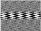
图3是本发明同偏振电光扫描直视合成孔径激光成像雷达发射系统中的两偏振光束抛物波面的干涉图。Fig. 3 is an interference diagram of parabolic wave surfaces of two polarized light beams in the same-polarization electro-optic scanning direct-looking synthetic aperture laser imaging radar transmitting system of the present invention.
具体实施方式Detailed ways
下面结合附图和实施例对本发明作进一步说明,但不应以此限制本发明的保护范围。The present invention will be further described below in conjunction with the accompanying drawings and embodiments, but the protection scope of the present invention should not be limited thereby.
先参阅图1,图1为本发明同偏振电光扫描直视合成孔径激光成像雷达发射系统结构图。由图可见,本发明同偏振电光扫描直视合成孔径激光成像雷达发射系统由激光器1、半波片2、孔径光阑3、第一偏振分束器4、第一1/4波片5、第一反射镜6、第一电光扫描器7、第一柱面镜8、第二反射镜9、第三反射镜10、第二电光扫描器11、第二柱面镜12、第二偏振分束器13、第二1/4波片14、第四反射镜15、发射望远镜主镜16,此外还有高压电源17和信号发生器18;所述的第一电光扫描器7出射面紧靠第一柱面镜8,所述的第二电光扫描器11出射面紧靠第二柱面镜12,所述的第一柱面镜8和第二柱面镜12均位于发射望远镜主镜16的前焦面,所述的高压电源17连接第一电光扫描器7和第二电光扫描器11,并由信号发生器18产生线性脉冲信号用以控制高压电源17产生线性变化的电压,所述的第一电光扫描器7和第二电光扫描器11均采用单块长方体电光晶体制成,其电光晶体的z方向为施加电场方向,每块电光晶体z方向表面采用两对互为反向平行的三角形电极施加电场,第一电光扫描器7和第二电光扫描器11所调制的相位符号相反。上述部件的位置关系如下:Referring to Fig. 1 first, Fig. 1 is a structural diagram of the same-polarization electro-optic scanning direct-view synthetic aperture imaging laser radar transmitting system of the present invention. As can be seen from the figure, the same polarization electro-optical scanning direct-looking synthetic aperture laser imaging radar transmitting system of the present invention consists of a laser 1, a half-
激光光源1输出的偏振光束经过所述的半波片2后获得所需的45°方向的偏振光束,该偏振光束通过孔径光阑3和第一偏振分束器4后在空间上被偏振分解为两个等强度的偏振正交的水平偏振光束和垂直偏振光束,所述的反射偏振光束为垂直偏振光束,透射的偏振光束为水平偏振光束,反射的垂直偏振光束经过第一1/4波片5和第一反射镜6后,由第一反射镜6反射再次进入第一1/4波片5,这时的垂直偏振光束偏振态转动90°变为水平偏振光束,因此第二次进入第一偏振分束器4时为透射光束,然后该透射的水平偏振光束经过第一电光扫描器7和第一柱面镜8,再由第二反射镜9反射并透射进入第二偏振分束器13;所述的第一偏振分束器4直接透射的水平偏振光束经过第三反射镜10后,进入第二电光扫描器11和第二柱面镜12,然后经过第二1/4波片14和第四反射镜15,由第四反射镜15反射的光束再次进入第二1/4波片14后,原来的水平偏振光束偏振态旋转90°变为垂直偏振光束,该垂直偏振光束经过第二偏振分束器13反射后,与透射的水平偏振光束重新组合为同轴同心且偏振正交的光束,由所述的发射望远镜主镜16发射向目标。The polarized beam output by the laser light source 1 passes through the half-
激光光源1出射的激光经过半波片2后产生45°偏振的偏振光束,采用孔径光阑3用以限制该偏振光束的振幅宽度,而后该偏振光束被第一偏振分束器4分束为水平偏振光束和垂直偏振光束,其中垂直偏振光束从第一偏振分束器4反射后两次经过1/4波片5后转变为水平偏振光束进入第一电光扫描器7和第一柱面镜8;由第一偏振分束器4直接透射的水平偏振光束经过第三反射镜10反射进入第二电光扫描器11和第二柱面镜镜12,因此两光束进入第一电光扫描器7和第二电光扫描器11的偏振态相同,线性相位相同,可为晶体的o光,也可以是晶体的e光,由于第一电光扫描器7和第二电光扫描器11均由一块长方体晶块组成,其z方向上镀上两对三角形电极,如图2所示,并对这两对三角形电极施加相反的电压时,是采用电场平行于z轴的横向运用,当光沿着y方向传播,当晶体的z轴即为垂直偏振光束的偏振态方向(取决于晶体的放置),则对于水平偏振光束,其偏振态垂直于晶体z轴,为晶体的o光;当晶体的z轴即为水平偏振光束的偏振态方向,则对于水平偏振光束,其偏振态平行于晶体z轴,为晶体的e光,晶体的两种放置位置产生不同的折射率变化,对应不同的电光扫描幅度。The laser light emitted by the laser light source 1 passes through the half-
当偏振态为电光扫描器的o光时,其折射率变化为When the polarization state is the o light of the electro-optic scanner, its refractive index changes as
其中,
因此当水平偏振光束从第一电光扫描器7和第一柱面镜8、第二电光扫描器11和第二柱面镜12后,该位置同为发射望远镜主镜16的前焦面,其发射场为Therefore when the horizontally polarized light beam is behind the first electro-
其中,
而后两水平偏振光束中的一支透过第二偏振分束器13后两次经过第二1/4波片14使其偏转态转变为垂直偏振光束,由第二偏振分束器13重新与另一水平偏振光束合束为同轴同心偏振正交的光束,由发射望远镜主镜16发射至远场目标处,其中内发射场经过发射望远镜主镜16的发射后,其在远场目标处的光场为内发射场光场的放大光场,其放大倍数是M=(Z-F)/F,Z是发射望远镜主镜16到远场目标面的距离,F是发射望远镜主镜的焦距。这时在目标面上形成水平偏振照明波前为:Then one of the two horizontally polarized light beams passes through the second polarization beam splitter 13 and passes through the second 1/4
式中,
式中,1/R3=1/R2+1/R1,一般设计时采用R2=R1。由于其中h为所加电压的厚度,U3由线性脉冲调制,从折射率变化可以看出线性调制交轨向的相位与晶体的长厚比成正比,与电压U成正比,因此通过施加线性电压可获得高响应速度的线性相位调制,这样就可以获得交轨向目标点横向位置的线性项相位调制,顺轨向目标点纵向位置为中心的二次项相位历程,是用以实现雷达二维平面目标成像的关键抛物波面相位。In the formula, 1/R3 =1/R2 +1/R1 , and R2 =R1 is generally used in design. because where h is the thickness of the applied voltage, U3 is modulated by a linear pulse, and it can be seen from the change of the refractive index that the phase of the linear modulation cross-track direction is proportional to the aspect ratio of the crystal and proportional to the voltage U, so by applying a linear voltage The linear phase modulation with high response speed can be obtained, so that the linear phase modulation of the cross-track to the horizontal position of the target point can be obtained, and the quadratic phase history of the along-track to the longitudinal position of the target point as the center is used to realize the radar two-dimensional Key parabolic phases for imaging planar targets.
当偏振态为电光扫描器的e光时,其折射率变化为When the polarization state is the e-ray of the electro-optical scanner, its refractive index changes as
其中,ne为晶体e光折射率,E3为施加在晶体z方向上的电场,γ33为在该方向上的电光系数。经过有两块施加电场反向的三角形LiNbO3晶体棱镜后,并且第二电光扫描器11电场施加方向与第一电光扫描器7的两对电极刚好相反,其x方向的相位延迟为in, ne is the optical refractive index of the crystal e, E3 is the electric field applied in the z direction of the crystal, and γ33 is the electro-optic coefficient in this direction. After passing through two triangular LiNbO3 crystal prisms with opposite applied electric fields, and the applied direction of the electric field of the second electro-
同样当水平偏振光束从第一电光扫描器7和第一柱面镜8、第二电光扫描器11和第二柱面镜12后,该位置同为发射望远镜主镜16的前焦面,其发射场为Equally when the horizontally polarized light beam is behind the first electro-
其中,
而后两水平偏振光束中的一支透过第二偏振分束器13后两次经过第二1/4波片14使其偏转态转变为垂直偏振光束,由第二偏振分束器13重新与另一水平偏振光束合束为同轴同心偏振正交的光束,由发射望远镜主镜16发射至远场目标处,其中内发射场经过发射望远镜主镜16的发射后,其在远场目标处的光场为内发射场光场的放大光场,其放大倍数是M=(Z-F)/F,Z是发射望远镜主镜16到远场目标面的距离,F是发射望远镜主镜的焦距。这时在目标面上形成水平偏振照明波前为:Then one of the two horizontally polarized light beams passes through the second polarization beam splitter 13 and passes through the second 1/4
式中,R1=M2f1,R2=M2f2,ts为慢时间,vy为飞机航线上慢时间的运动速度,公式中最后一项与Z有关的相位二次项是发射光束夫琅禾费衍射传播产生的远场背景相位二次项。两偏振光束的照明的公共区域为有效的照明条幅,此时,有效照明光斑的空间相位差具有抛物等位线:In the formula, R1 =M2 f1 , R2 =M2 f2 , ts is the slow time, vy is the moving speed of the slow time on the flight route, the last item in the formula is the phase quadratic term related to Z is the emitted beam Far-field background phase quadratic term due to Fraunhofer diffractive propagation. The common area illuminated by the two polarized light beams is the effective illumination strip. At this time, the spatial phase difference of the effective illumination spot has a parabolic equipotential line:

式中,1/R3=1/R2+1/R1,一般设计时采用R2=R1。由于
成像分辨率采用相干点扩散函数最小值半宽度来表达,由于照明光斑在交轨向的角度扫描范围为(-kθmax,kθmax),k≤0.5为光束中心偏转的可能设计值,

同理,顺轨向的分辨率为Similarly, the along-track resolution is
一般情况下,设计x,y方向的分辨率相等,有dx=dy,理想的设计最大偏向角为
由此可见,表示成像分辨率的顺轨向的相干点扩展函数最小值半宽度由内发射光场的相对口径所决定,随工作距离增长而增大;而交轨向的相干点扩展函数最小值半宽度由内发射光场的相对口径和其电光晶体长厚比和晶体性质与所施加的电场所决定,同样随工作距离增长而增大。It can be seen that the minimum half-width of the coherent point spread function in the along-track direction of the imaging resolution is determined by the relative aperture of the internal emission light field, and increases with the increase of the working distance; while the coherent point spread function in the cross-track direction is the smallest The value half-width is determined by the relative aperture of the internal emission light field, the aspect ratio of the electro-optic crystal, the crystal properties and the applied electric field, and it also increases with the working distance.
图1是本发明最佳实施例的结构示意图,其具体结构和参数如下:Fig. 1 is the structural representation of preferred embodiment of the present invention, and its concrete structure and parameter are as follows:
本实施例性能指标要求为:飞机机载观察,平台运动速度为40m/s;观察高度Z=5km,要求激光照明有效条幅宽度为25m×25m,且分辨率全宽度为有dx=40mm,dy=40mm。The performance index requirements of this embodiment are: aircraft airborne observation, platform movement speed is 40m/s; observation height Z=5km, the effective banner width of laser lighting is required to be 25m×25m, and the full resolution width isdx =40mm, dy =40 mm.
其中发射激光波长采用0.532μm,第一电光扫描器7和第二电光扫描器11均采用LiNbO3晶体,他们的尺寸均为5mm×5mm×50mm,在其z方向制作两对平行对称的三角形电极,施加的最大电压为8000V,因此其可获得的最大线性调制角度为θmax=0.034rad,发射望远镜主镜16的焦距设计为F=1m,因此距离放大倍数为M=5×10³,发射望远镜主镜16口径大约为100mm,目标面有效照明光斑尺寸为50m×50m。第一电光扫描器7和第二电光扫描器11的扫描范围为(-0.5θmax,0.5θmax),据此,其成像分辨率的设计为dx=40mm,设计x,y方向的分辨率相等,有dx=dy,则
Claims (4)
Priority Applications (1)
| Application Number | Priority Date | Filing Date | Title |
|---|---|---|---|
| CN201310461223.3ACN103543444B (en) | 2013-09-30 | 2013-09-30 | With polarization electropical scanning Orthoptic synthetic aperture laser imaging radar emission coefficient |
Applications Claiming Priority (1)
| Application Number | Priority Date | Filing Date | Title |
|---|---|---|---|
| CN201310461223.3ACN103543444B (en) | 2013-09-30 | 2013-09-30 | With polarization electropical scanning Orthoptic synthetic aperture laser imaging radar emission coefficient |
Publications (2)
| Publication Number | Publication Date |
|---|---|
| CN103543444Atrue CN103543444A (en) | 2014-01-29 |
| CN103543444B CN103543444B (en) | 2016-01-20 |
Family
ID=49967066
Family Applications (1)
| Application Number | Title | Priority Date | Filing Date |
|---|---|---|---|
| CN201310461223.3AActiveCN103543444B (en) | 2013-09-30 | 2013-09-30 | With polarization electropical scanning Orthoptic synthetic aperture laser imaging radar emission coefficient |
Country Status (1)
| Country | Link |
|---|---|
| CN (1) | CN103543444B (en) |
Cited By (5)
| Publication number | Priority date | Publication date | Assignee | Title |
|---|---|---|---|---|
| CN104251994A (en)* | 2014-09-11 | 2014-12-31 | 上海卫星工程研究所 | Control-point-free satellite precise positioning system and method realized through long-baseline laser ranging |
| CN105527705A (en)* | 2016-01-19 | 2016-04-27 | 中国科学院上海光学精密机械研究所 | Twice-reflection laser scanning angle trigger device |
| CN109856427A (en)* | 2017-11-30 | 2019-06-07 | 清华大学 | Detection device, detection system and the detection method of surface force distribution |
| CN109946710A (en)* | 2019-03-29 | 2019-06-28 | 中国科学院上海技术物理研究所 | A dual-wavelength multi-polarization laser imaging device |
| CN110118960A (en)* | 2019-05-29 | 2019-08-13 | 深圳市镭神智能系统有限公司 | Laser radar |
Citations (5)
| Publication number | Priority date | Publication date | Assignee | Title |
|---|---|---|---|---|
| CN1299472A (en)* | 1998-04-08 | 2001-06-13 | 科英应用技术公司 | High speed electro-optic modulator |
| CN102279477A (en)* | 2010-06-09 | 2011-12-14 | 上海微电子装备有限公司 | Electro-optical phase modulator having automatic resonant frequency adjusting function |
| CN102435996A (en)* | 2011-12-02 | 2012-05-02 | 中国科学院上海光学精密机械研究所 | Direct-view synthetic aperture laser imaging radar |
| CN103245939A (en)* | 2013-05-22 | 2013-08-14 | 中国科学院上海光学精密机械研究所 | Direct wave face conversion scanner for direct sight synthetic aperture laser imaging radar emitting light beam |
| CN103293524A (en)* | 2013-05-15 | 2013-09-11 | 中国科学院上海光学精密机械研究所 | Michelson direct-vision synthetic aperture laser imaging radar transmitter |
- 2013
- 2013-09-30CNCN201310461223.3Apatent/CN103543444B/enactiveActive
Patent Citations (5)
| Publication number | Priority date | Publication date | Assignee | Title |
|---|---|---|---|---|
| CN1299472A (en)* | 1998-04-08 | 2001-06-13 | 科英应用技术公司 | High speed electro-optic modulator |
| CN102279477A (en)* | 2010-06-09 | 2011-12-14 | 上海微电子装备有限公司 | Electro-optical phase modulator having automatic resonant frequency adjusting function |
| CN102435996A (en)* | 2011-12-02 | 2012-05-02 | 中国科学院上海光学精密机械研究所 | Direct-view synthetic aperture laser imaging radar |
| CN103293524A (en)* | 2013-05-15 | 2013-09-11 | 中国科学院上海光学精密机械研究所 | Michelson direct-vision synthetic aperture laser imaging radar transmitter |
| CN103245939A (en)* | 2013-05-22 | 2013-08-14 | 中国科学院上海光学精密机械研究所 | Direct wave face conversion scanner for direct sight synthetic aperture laser imaging radar emitting light beam |
Cited By (7)
| Publication number | Priority date | Publication date | Assignee | Title |
|---|---|---|---|---|
| CN104251994A (en)* | 2014-09-11 | 2014-12-31 | 上海卫星工程研究所 | Control-point-free satellite precise positioning system and method realized through long-baseline laser ranging |
| CN105527705A (en)* | 2016-01-19 | 2016-04-27 | 中国科学院上海光学精密机械研究所 | Twice-reflection laser scanning angle trigger device |
| CN109856427A (en)* | 2017-11-30 | 2019-06-07 | 清华大学 | Detection device, detection system and the detection method of surface force distribution |
| CN109946710A (en)* | 2019-03-29 | 2019-06-28 | 中国科学院上海技术物理研究所 | A dual-wavelength multi-polarization laser imaging device |
| CN109946710B (en)* | 2019-03-29 | 2023-12-26 | 中国科学院上海技术物理研究所 | Dual-wavelength multi-polarization laser imaging device |
| CN110118960A (en)* | 2019-05-29 | 2019-08-13 | 深圳市镭神智能系统有限公司 | Laser radar |
| CN110118960B (en)* | 2019-05-29 | 2023-03-10 | 深圳市镭神智能系统有限公司 | Laser radar |
Also Published As
| Publication number | Publication date |
|---|---|
| CN103543444B (en) | 2016-01-20 |
Similar Documents
| Publication | Publication Date | Title |
|---|---|---|
| WO2020259327A1 (en) | Light detection and ranging and light detection and ranging detection method | |
| CN103293524B (en) | Michelson direct-vision synthetic aperture laser imaging radar transmitter | |
| CN103245939B (en) | Direct wave face conversion scanner for direct sight synthetic aperture laser imaging radar emitting light beam | |
| CN111650601B (en) | High-resolution 3D imaging method and device for vehicle-mounted coherent laser radar | |
| CN103543444B (en) | With polarization electropical scanning Orthoptic synthetic aperture laser imaging radar emission coefficient | |
| CN109270551B (en) | An area array scanning laser long-distance three-dimensional measurement system | |
| CN102435996B (en) | Orthoptic synthetic aperture laser imaging radar | |
| US9329081B1 (en) | Target feature integrated laser phase compensation system | |
| CN108574533B (en) | A common aperture laser communication optical transceiver based on optical phased array | |
| CN103543443B (en) | Two-way electropical scanning Orthoptic synthetic aperture laser imaging radar emission coefficient | |
| CN109375230B (en) | High-precision laser echo frequency modulation system and method | |
| CN109991623A (en) | A distributed lidar | |
| CN109444848B (en) | Scanning device and scanning method thereof, and laser radar | |
| CN113484876B (en) | Laser three-dimensional staring imaging system | |
| Luan et al. | Down-looking synthetic aperture imaging ladar demonstrator and its experiments over 1.2 km outdoor | |
| CN103983979A (en) | Synthetic aperture laser imaging radar based on M sequence phase encoding and cross-polarization multiplexing | |
| CN102096071A (en) | Relay light-amplified laser ranging method and device for cooperative target | |
| CN103278809A (en) | Orthoptic synthesis aperture laser imaging radar single-prism rotary transmitting device | |
| CN104965206A (en) | Phase encoding cross-polarization synthetic aperture laser imaging radar | |
| CN114779212A (en) | Laser radar | |
| CN101344594B (en) | Scanning Synthetic Aperture LiDAR | |
| CN103439703A (en) | Reflecting type double-faced translating transmitting device for direct-view synthetic aperture laser imaging radar | |
| CN103744071A (en) | Linear scanning device for aplanatism wave surface transformation for orthophoria synthetic aperture laser imaging radar | |
| CN103954954B (en) | Orthoptic synthetic aperture laser imaging radar reflective electrooptic scanning means | |
| CN107102311B (en) | Direct-looking synthetic aperture laser imaging radar rotating reflection wave surface conversion scanning device |
Legal Events
| Date | Code | Title | Description |
|---|---|---|---|
| C06 | Publication | ||
| PB01 | Publication | ||
| SE01 | Entry into force of request for substantive examination | ||
| SE01 | Entry into force of request for substantive examination | ||
| C14 | Grant of patent or utility model | ||
| GR01 | Patent grant |