CN103536324A - Anastomat and indicating device of anastomat - Google Patents
Anastomat and indicating device of anastomatDownload PDFInfo
- Publication number
- CN103536324A CN103536324ACN201310456645.1ACN201310456645ACN103536324ACN 103536324 ACN103536324 ACN 103536324ACN 201310456645 ACN201310456645 ACN 201310456645ACN 103536324 ACN103536324 ACN 103536324A
- Authority
- CN
- China
- Prior art keywords
- indicating device
- stapler
- card
- indicating
- elastic
- Prior art date
- Legal status (The legal status is an assumption and is not a legal conclusion. Google has not performed a legal analysis and makes no representation as to the accuracy of the status listed.)
- Granted
Links
- 238000011084recoveryMethods0.000claimsdescription7
- 230000000903blocking effectEffects0.000claimsdescription5
- 239000002184metalSubstances0.000claimsdescription4
- 238000000034methodMethods0.000description3
- 238000001356surgical procedureMethods0.000description3
- 230000009471actionEffects0.000description2
- 238000012986modificationMethods0.000description2
- 230000004048modificationEffects0.000description2
- 239000008280bloodSubstances0.000description1
- 210000004369bloodAnatomy0.000description1
- 238000011161developmentMethods0.000description1
- 239000003814drugSubstances0.000description1
- 238000005516engineering processMethods0.000description1
- 238000011902gastrointestinal surgeryMethods0.000description1
- 208000015181infectious diseaseDiseases0.000description1
- 230000002980postoperative effectEffects0.000description1
- 230000008569processEffects0.000description1
- 238000012827research and developmentMethods0.000description1
- 210000000115thoracic cavityAnatomy0.000description1
Images

Classifications
- A—HUMAN NECESSITIES
- A61—MEDICAL OR VETERINARY SCIENCE; HYGIENE
- A61B—DIAGNOSIS; SURGERY; IDENTIFICATION
- A61B17/00—Surgical instruments, devices or methods
- A61B17/11—Surgical instruments, devices or methods for performing anastomosis; Buttons for anastomosis
- A61B17/115—Staplers for performing anastomosis, e.g. in a single operation
- A—HUMAN NECESSITIES
- A61—MEDICAL OR VETERINARY SCIENCE; HYGIENE
- A61B—DIAGNOSIS; SURGERY; IDENTIFICATION
- A61B90/00—Instruments, implements or accessories specially adapted for surgery or diagnosis and not covered by any of the groups A61B1/00 - A61B50/00, e.g. for luxation treatment or for protecting wound edges
- A61B90/08—Accessories or related features not otherwise provided for
- A61B2090/0807—Indication means
- A61B2090/0808—Indication means for indicating correct assembly of components, e.g. of the surgical apparatus
Landscapes
- Health & Medical Sciences (AREA)
- Life Sciences & Earth Sciences (AREA)
- Surgery (AREA)
- Heart & Thoracic Surgery (AREA)
- Engineering & Computer Science (AREA)
- Biomedical Technology (AREA)
- Nuclear Medicine, Radiotherapy & Molecular Imaging (AREA)
- Medical Informatics (AREA)
- Molecular Biology (AREA)
- Animal Behavior & Ethology (AREA)
- General Health & Medical Sciences (AREA)
- Public Health (AREA)
- Veterinary Medicine (AREA)
- Clamps And Clips (AREA)
- Portable Nailing Machines And Staplers (AREA)
Abstract
Translated fromChinese
Description
Translated fromChinese技术领域technical field
本发明涉及医疗器械技术领域,特别涉及一种吻合器的指示装置。本发明还涉及一种包括上述指示装置的吻合器。The invention relates to the technical field of medical instruments, in particular to an indicating device for a stapler. The present invention also relates to a stapler comprising the above-mentioned indicating device.
背景技术Background technique
在医学科学的外科手术中,自从20世纪60年代发明第一把缝钉类产品以来,医用吻合器已成为辅助于刀口缝合过程中的必不可少的一种医疗器械。随着医学的发展和产品研发,越来越多功能的缝钉类产品应用于临床。适用范围已涉及到胃肠外科、肝胆外科、胸外科、泌尿外科、妇产科等各个领域,成为医生必不可少的工具之一。对于患者具有术中较少出血、较少手术时间、用器械代替手工从而减少由于手工而造成的误差、避免感染、术后功能恢复快等多种优势。In the surgical operation of medical science, since the first staple product was invented in the 1960s, the medical stapler has become an indispensable medical device to assist in the process of incision suturing. With the development of medicine and product research and development, more and more multifunctional staple products are used in clinical practice. The scope of application has been involved in various fields such as gastrointestinal surgery, hepatobiliary surgery, thoracic surgery, urology, obstetrics and gynecology, and has become one of the indispensable tools for doctors. For patients, it has many advantages such as less blood loss during operation, less operation time, using instruments instead of manual operation to reduce errors caused by manual operation, avoiding infection, and quick recovery of postoperative function.
一种典型的吻合器的指示装置,包括手柄、定位板、指针和指示卡,指示卡固定在吻合器的壳体上,吻合器工作时,手柄带动定位板运动,定位板带动指针运动,指示卡上设置有标记,观察指针在指示卡上的运动位置,从而判断吻合器的运动状态。但是组装完成的吻合器,由于零件的配合精度不高,导致吻合器的初始状态,指针没有处于指示卡的初始位置,吻合器的指示装置的精度较低,从而吻合器在手术中的操作难度较大。A typical indicating device for a stapler, including a handle, a positioning plate, a pointer and an indicating card, the indicating card is fixed on the shell of the stapler, when the stapler is working, the handle drives the positioning plate to move, and the positioning plate drives the pointer to move, indicating Marks are set on the card, and the movement status of the stapler can be judged by observing the movement position of the pointer on the indication card. However, for the assembled stapler, due to the low matching accuracy of the parts, the initial state of the stapler, the pointer is not at the initial position of the indicator card, and the accuracy of the indicator device of the stapler is low, so the operation of the stapler is difficult during surgery. larger.
因此,如何提高吻合器的指示装置的精度,是本领域技术人员目前需要解决的技术问题。Therefore, how to improve the accuracy of the indicating device of the stapler is a technical problem to be solved by those skilled in the art.
发明内容Contents of the invention
本发明的目的是提供一种吻合器的指示装置,该指示装置的精度较高。本发明的另一目的是提供一种包括上述指示装置的吻合器。The purpose of the present invention is to provide an indicating device for a stapler, which has high precision. Another object of the present invention is to provide a stapler comprising the above-mentioned indicating device.
为了实现上述目的,本发明提供了一种吻合器的指示装置,包括设置于所述吻合器的壳体上的指示卡,还包括分别安装在所述指示卡两侧的弹性卡件和弹性回复件、与所述弹性卡件抵接的调节件,所述调节件设置于所述壳体的调节孔内。In order to achieve the above object, the present invention provides an indicating device for an anastomat, which includes an indicating card arranged on the housing of the anastomat, and also includes elastic clips and elastic return elements mounted on both sides of the indicating card, respectively. A piece, an adjustment piece abutted against the elastic clip, the adjustment piece is arranged in the adjustment hole of the housing.
优选地,所述弹性回复件为弹簧。Preferably, the elastic recovery member is a spring.
优选地,所述弹性回复件为弹性金属片。Preferably, the elastic recovery member is an elastic metal sheet.
优选地,所述指示卡的一侧设置有阻挡件。Preferably, one side of the indicator card is provided with a blocking member.
优选地,所述指示卡的两侧均设置有阻挡件。Preferably, both sides of the indicator card are provided with blocking members.
优选地,所述调节件为调节螺栓。Preferably, the adjusting member is an adjusting bolt.
优选地,所述调节件与所述调节孔为过紧配合。Preferably, the adjusting member is in an over-tight fit with the adjusting hole.
本发明还提供了一种吻合器,包括器身以及与所述器身连接的指示装置,所述指示装置为上述任一项所述的指示装置。The present invention also provides a stapler, comprising a body and an indicating device connected to the body, and the indicating device is the indicating device described in any one of the above.
本发明提供的吻合器的指示装置,包括设置于吻合器的壳体上的指示卡,还包括分别安装在指示卡两侧的弹性卡件和弹性回复件、与弹性卡件抵接的调节件,调节件设置于壳体的调节孔内。当在使用吻合器时,可以观察吻合器的指针处于指示卡的位置是否为初始位置,当指针的位置没有与指示卡的初始位置标记相对应时,可以调节调节件,从而使弹性卡件伸长或缩短,在弹性回复件的作用下,指示卡可以左右移动,从而使指示卡的初始位置标记与指针相对应。The indicating device for an anastomat provided by the present invention includes an indicating card arranged on the shell of the anastomat, and also includes an elastic clip and an elastic return member respectively installed on both sides of the indicator card, and an adjustment member abutting against the elastic clip , the adjusting member is arranged in the adjusting hole of the casing. When using the stapler, you can observe whether the pointer of the stapler is at the initial position of the indicator card. When the position of the pointer does not correspond to the initial position mark of the indicator card, you can adjust the adjustment member so that the elastic card is extended. Long or shorten, under the action of the elastic return piece, the indicator card can move left and right, so that the initial position mark of the indicator card corresponds to the pointer.
通过上述描述可知,相对于背景技术,本发明提供的吻合器的指示装置,可以调节指示卡的位置使指示卡调节到精准的初始位置,从而提高了吻合器的指示装置的精度。From the above description, it can be seen that, compared with the background technology, the indicating device of the stapler provided by the present invention can adjust the position of the indicating card so that the indicating card can be adjusted to a precise initial position, thereby improving the accuracy of the indicating device of the stapler.
附图说明Description of drawings
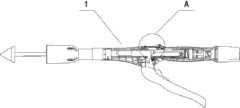
图1为本发明提供的吻合器的结构示意图;Fig. 1 is the structural representation of the stapler provided by the present invention;
图2为图1所示的吻合器的A处的指示装置的结构示意图;Fig. 2 is a schematic structural view of an indicating device at A of the stapler shown in Fig. 1;
图3为图1所示的吻合器的指示装置的爆炸图。Fig. 3 is an exploded view of the indicating device of the stapler shown in Fig. 1 .
具体实施方式Detailed ways
本发明的核心是提供一种吻合器的指示装置,该指示装置的精度较高。本发明的另一核心是提供一种包括上述指示装置的吻合器。The core of the present invention is to provide an indicating device of a stapler, and the indicating device has high precision. Another core of the present invention is to provide a stapler including the above-mentioned indicating device.
为了使本领域技术人员更好地理解本发明的技术方案,下面将结合附图和具体实施例对本发明作进一步的详细说明。In order to enable those skilled in the art to better understand the technical solutions of the present invention, the present invention will be further described in detail below in conjunction with the accompanying drawings and specific embodiments.
请参考图1-图3,在一种具体实施方式中,本发明实施例提供的吻合器1的指示装置,包括设置于吻合器1的壳体上的指示卡5,还包括分别安装在指示卡5两侧的弹性卡件2和弹性回复件3、与弹性卡件2抵接的调节件4,调节件4设置于壳体的调节孔内。当在使用吻合器1时,可以观察吻合器1的指针处于指示卡5的位置是否为初始位置,当指针的位置没有与指示卡5的初始位置标记相对应时,可以调节调节件4,从而使弹性卡件2伸长或缩短,在弹性回复件3的作用下,指示卡5可以左右移动,从而使指示卡5的初始位置标记与指针相对应。本发明提供的吻合器1的指示装置,可以调节指示卡5的位置使指示卡5调节到精准的初始位置,从而提高了吻合器1的指示装置的精度。上述弹性回复件3可以为弹簧。上述调节件4可以为调节螺栓。Please refer to Fig. 1-Fig. 3, in a specific implementation mode, the indicating device of the
此外,弹性回复件3可以为弹性金属片,弹性金属片的稳定性较好,便于安装在吻合器1的壳体上。In addition, the
另外,指示卡5的一侧设置有阻挡件,阻挡件可以更好地阻挡弹性卡件2和弹性回复件3,使指示卡5更稳定。也可以两侧均不设置阻挡件,指示卡5的两端直接与弹性卡件2和弹性金属片抵接。In addition, one side of the
进一步地,指示卡5的两侧均设置有阻挡件,这样可以更好地阻挡弹性卡件2和弹性回复件3,进一步提高了指示卡5的稳定性。Further, stoppers are provided on both sides of the
更进一步地,上述调节件4与上述调节孔为过紧配合。这样可以通过摩擦力来使调节件4固定在调节孔内,Furthermore, the above-mentioned
本发明实施例所提供的吻合器,包括器身以及与器身连接的上述指示装置,其他部分的结构可以参照现有技术,本文不再赘述。The stapler provided by the embodiment of the present invention includes a body and the above-mentioned indicating device connected to the body. The structure of other parts can refer to the prior art, and will not be repeated here.
以上对本发明所提供的吻合器及其指示装置进行了详细介绍。本文中应用了具体个例对本发明的原理及实施方式进行了阐述,以上实施例的说明只是用于帮助理解本发明的方法及其核心思想,并非对本发明保护范围的限定。应当指出,对于本技术领域的普通技术人员来说,在不脱离本发明原理的前提下,还可以对本发明进行若干改进和修饰,这些改进和修饰也落入本发明权利要求的保护范围内。The stapler and its indicating device provided by the present invention have been introduced in detail above. In this paper, specific examples are used to illustrate the principle and implementation of the present invention. The descriptions of the above embodiments are only used to help understand the method and core idea of the present invention, and are not intended to limit the protection scope of the present invention. It should be pointed out that for those skilled in the art, without departing from the principle of the present invention, some improvements and modifications can be made to the present invention, and these improvements and modifications also fall within the protection scope of the claims of the present invention.
Claims (8)
Translated fromChinesePriority Applications (1)
| Application Number | Priority Date | Filing Date | Title |
|---|---|---|---|
| CN201310456645.1ACN103536324B (en) | 2013-09-29 | 2013-09-29 | Anastomat and indicating device of anastomat |
Applications Claiming Priority (1)
| Application Number | Priority Date | Filing Date | Title |
|---|---|---|---|
| CN201310456645.1ACN103536324B (en) | 2013-09-29 | 2013-09-29 | Anastomat and indicating device of anastomat |
Publications (2)
| Publication Number | Publication Date |
|---|---|
| CN103536324Atrue CN103536324A (en) | 2014-01-29 |
| CN103536324B CN103536324B (en) | 2017-02-15 |
Family
ID=49960458
Family Applications (1)
| Application Number | Title | Priority Date | Filing Date |
|---|---|---|---|
| CN201310456645.1AActiveCN103536324B (en) | 2013-09-29 | 2013-09-29 | Anastomat and indicating device of anastomat |
Country Status (1)
| Country | Link |
|---|---|
| CN (1) | CN103536324B (en) |
Citations (5)
| Publication number | Priority date | Publication date | Assignee | Title |
|---|---|---|---|---|
| EP0656190A2 (en)* | 1993-10-08 | 1995-06-07 | United States Surgical Corporation | Apparatus for applying surgical clips |
| US6601748B1 (en)* | 2001-12-15 | 2003-08-05 | Modern Medical Equip. Mfg., Ltd. | Surgical stapler |
| CN101856250A (en)* | 2010-06-07 | 2010-10-13 | 常州威克医疗器械有限公司 | Disposable automatic safety circular anastomat |
| US20110155782A1 (en)* | 2009-12-31 | 2011-06-30 | Anandram Natarajan | Indicator for surgical stapler |
| CN203506797U (en)* | 2013-09-29 | 2014-04-02 | 北京中法派尔特医疗设备有限公司 | Stapler and indicating device thereof |
- 2013
- 2013-09-29CNCN201310456645.1Apatent/CN103536324B/enactiveActive
Patent Citations (5)
| Publication number | Priority date | Publication date | Assignee | Title |
|---|---|---|---|---|
| EP0656190A2 (en)* | 1993-10-08 | 1995-06-07 | United States Surgical Corporation | Apparatus for applying surgical clips |
| US6601748B1 (en)* | 2001-12-15 | 2003-08-05 | Modern Medical Equip. Mfg., Ltd. | Surgical stapler |
| US20110155782A1 (en)* | 2009-12-31 | 2011-06-30 | Anandram Natarajan | Indicator for surgical stapler |
| CN101856250A (en)* | 2010-06-07 | 2010-10-13 | 常州威克医疗器械有限公司 | Disposable automatic safety circular anastomat |
| CN203506797U (en)* | 2013-09-29 | 2014-04-02 | 北京中法派尔特医疗设备有限公司 | Stapler and indicating device thereof |
Also Published As
| Publication number | Publication date |
|---|---|
| CN103536324B (en) | 2017-02-15 |
Similar Documents
| Publication | Publication Date | Title |
|---|---|---|
| RU2014127518A (en) | CASSETTE DEVICE FOR LINEAR STAPLING INSTRUMENT OF REUSABLE USE FOR MEASURING FABRIC THICKNESS | |
| WO2022088537A1 (en) | Interventional surgical robot guide wire friction feedback device and method | |
| MX2009004509A (en) | FORCE ESTIMATION FOR A MINIMALLY INVASIVE ROBOTIC SURGICAL SYSTEM. | |
| JP2016508410A5 (en) | ||
| WO2012129292A3 (en) | Energy-based scissors device | |
| CN103536324B (en) | Anastomat and indicating device of anastomat | |
| CN105796107A (en) | Intelligent appliance for measuring tissue thickness at high resolution factor | |
| EP2663246A1 (en) | Distance indicator | |
| CN103536334B (en) | Anastomat and pointer adjustment device thereof | |
| CN203506797U (en) | Stapler and indicating device thereof | |
| CN103536332A (en) | Anastomat and safety device of anastomat | |
| CN103610482A (en) | Stapler and inner safety device thereof | |
| CN103536335B (en) | Anastomat and insurance adjusting means thereof | |
| CN203506810U (en) | Stapler and pointer adjusting device thereof | |
| CN103845092B (en) | Purse-string forceps and suggestion device thereof | |
| CN107198523B (en) | Intelligent pressure-sensitive measuring device for resection of distal femur tumor | |
| CN110693540A (en) | Combined minimally invasive surgical instrument | |
| CN103494625B (en) | A kind of purse-string forceps automatically | |
| CN205831795U (en) | The intelligent apparatus of high-resolution measurement tissue thickness | |
| CN205144637U (en) | Count indicating device and adopt this count indicating device's medical instrument | |
| CN203506809U (en) | Stapler and safety adjusting device thereof | |
| CN209032635U (en) | A rapid positioning mechanism for tapered surfaces | |
| CN210843348U (en) | Puncture needle guiding device suitable for wide-face puncture through B-ultrasonic probe | |
| CN209004198U (en) | Navigation pin and navigation and positioning component | |
| TWM514830U (en) | Ultrasound probe guiding device |
Legal Events
| Date | Code | Title | Description |
|---|---|---|---|
| C06 | Publication | ||
| PB01 | Publication | ||
| SE01 | Entry into force of request for substantive examination | ||
| SE01 | Entry into force of request for substantive examination | ||
| DD01 | Delivery of document by public notice | Addressee:B. J. ZH. F. PANTHER MEDICAL EQUIPMENT Co.,Ltd. Document name:the First Notification of an Office Action | |
| C53 | Correction of patent of invention or patent application | ||
| CB02 | Change of applicant information | Address after:102208 Beijing City, Changping District Beiqijia town Zhenggezhuang village Hongfu building room 61704 Applicant after:B. J. ZH. F. PANTHER MEDICAL EQUIPMENT Co.,Ltd. Address before:Beijing City, Chaoyang District Wangjing two district 100018 emerging industries in the Garden District Litse No. 208 building 3 floor 3305A room 3 Applicant before:B. J. ZH. F. PANTHER MEDICAL EQUIPMENT Co.,Ltd. | |
| COR | Change of bibliographic data | Free format text:CORRECT: ADDRESS; FROM: 100018 CHAOYANG, BEIJING TO: 102208 CHANGPING, BEIJING | |
| CB02 | Change of applicant information | Address after:102200 Changping District science and Technology Park, Beijing torch street, building 28, building three, floor 1 Applicant after:B.J. ZH. F. PANTHER MEDICAL EQUIPMENT Co.,Ltd. Address before:102208 Beijing City, Changping District Beiqijia town Zhenggezhuang village Hongfu building room 61704 Applicant before:B. J. ZH. F. PANTHER MEDICAL EQUIPMENT Co.,Ltd. | |
| COR | Change of bibliographic data | ||
| C14 | Grant of patent or utility model | ||
| GR01 | Patent grant | ||
| CP03 | Change of name, title or address | Address after:No. 8 Shangcheng Road, Beiqijia Town, Changping District, Beijing 102200 Patentee after:B.J. ZH. F. PANTHER MEDICAL EQUIPMENT Co.,Ltd. Country or region after:China Address before:102200 three floor, 1 floor, 28 torch street, Changping District science and Technology Park, Beijing. Patentee before:B.J. ZH. F. PANTHER MEDICAL EQUIPMENT Co.,Ltd. Country or region before:China | |
| CP03 | Change of name, title or address |