CN103534068A - Wind turbine assembly and management robot and wind turbine system incorporating it - Google Patents
Wind turbine assembly and management robot and wind turbine system incorporating itDownload PDFInfo
- Publication number
- CN103534068A CN103534068ACN201180067181.4ACN201180067181ACN103534068ACN 103534068 ACN103534068 ACN 103534068ACN 201180067181 ACN201180067181 ACN 201180067181ACN 103534068 ACN103534068 ACN 103534068A
- Authority
- CN
- China
- Prior art keywords
- unit
- robot
- wind turbine
- value
- identification
- Prior art date
- Legal status (The legal status is an assumption and is not a legal conclusion. Google has not performed a legal analysis and makes no representation as to the accuracy of the status listed.)
- Granted
Links
Images


Classifications
- B—PERFORMING OPERATIONS; TRANSPORTING
- B25—HAND TOOLS; PORTABLE POWER-DRIVEN TOOLS; MANIPULATORS
- B25J—MANIPULATORS; CHAMBERS PROVIDED WITH MANIPULATION DEVICES
- B25J11/00—Manipulators not otherwise provided for
- B—PERFORMING OPERATIONS; TRANSPORTING
- B25—HAND TOOLS; PORTABLE POWER-DRIVEN TOOLS; MANIPULATORS
- B25J—MANIPULATORS; CHAMBERS PROVIDED WITH MANIPULATION DEVICES
- B25J15/00—Gripping heads and other end effectors
- B25J15/0019—End effectors other than grippers
- B—PERFORMING OPERATIONS; TRANSPORTING
- B25—HAND TOOLS; PORTABLE POWER-DRIVEN TOOLS; MANIPULATORS
- B25J—MANIPULATORS; CHAMBERS PROVIDED WITH MANIPULATION DEVICES
- B25J15/00—Gripping heads and other end effectors
- B25J15/04—Gripping heads and other end effectors with provision for the remote detachment or exchange of the head or parts thereof
- B—PERFORMING OPERATIONS; TRANSPORTING
- B25—HAND TOOLS; PORTABLE POWER-DRIVEN TOOLS; MANIPULATORS
- B25J—MANIPULATORS; CHAMBERS PROVIDED WITH MANIPULATION DEVICES
- B25J5/00—Manipulators mounted on wheels or on carriages
- B—PERFORMING OPERATIONS; TRANSPORTING
- B25—HAND TOOLS; PORTABLE POWER-DRIVEN TOOLS; MANIPULATORS
- B25J—MANIPULATORS; CHAMBERS PROVIDED WITH MANIPULATION DEVICES
- B25J9/00—Programme-controlled manipulators
- B25J9/16—Programme controls
- B25J9/1694—Programme controls characterised by use of sensors other than normal servo-feedback from position, speed or acceleration sensors, perception control, multi-sensor controlled systems, sensor fusion
- B25J9/1697—Vision controlled systems
- F—MECHANICAL ENGINEERING; LIGHTING; HEATING; WEAPONS; BLASTING
- F03—MACHINES OR ENGINES FOR LIQUIDS; WIND, SPRING, OR WEIGHT MOTORS; PRODUCING MECHANICAL POWER OR A REACTIVE PROPULSIVE THRUST, NOT OTHERWISE PROVIDED FOR
- F03D—WIND MOTORS
- F03D13/00—Assembly, mounting or commissioning of wind motors; Arrangements specially adapted for transporting wind motor components
- F03D13/10—Assembly of wind motors; Arrangements for erecting wind motors
- F—MECHANICAL ENGINEERING; LIGHTING; HEATING; WEAPONS; BLASTING
- F03—MACHINES OR ENGINES FOR LIQUIDS; WIND, SPRING, OR WEIGHT MOTORS; PRODUCING MECHANICAL POWER OR A REACTIVE PROPULSIVE THRUST, NOT OTHERWISE PROVIDED FOR
- F03D—WIND MOTORS
- F03D80/00—Details, components or accessories not provided for in groups F03D1/00 - F03D17/00
- F03D80/50—Maintenance or repair
- F—MECHANICAL ENGINEERING; LIGHTING; HEATING; WEAPONS; BLASTING
- F05—INDEXING SCHEMES RELATING TO ENGINES OR PUMPS IN VARIOUS SUBCLASSES OF CLASSES F01-F04
- F05B—INDEXING SCHEME RELATING TO WIND, SPRING, WEIGHT, INERTIA OR LIKE MOTORS, TO MACHINES OR ENGINES FOR LIQUIDS COVERED BY SUBCLASSES F03B, F03D AND F03G
- F05B2230/00—Manufacture
- F05B2230/80—Repairing, retrofitting or upgrading methods
- F—MECHANICAL ENGINEERING; LIGHTING; HEATING; WEAPONS; BLASTING
- F05—INDEXING SCHEMES RELATING TO ENGINES OR PUMPS IN VARIOUS SUBCLASSES OF CLASSES F01-F04
- F05B—INDEXING SCHEME RELATING TO WIND, SPRING, WEIGHT, INERTIA OR LIKE MOTORS, TO MACHINES OR ENGINES FOR LIQUIDS COVERED BY SUBCLASSES F03B, F03D AND F03G
- F05B2240/00—Components
- F05B2240/90—Mounting on supporting structures or systems
- F05B2240/91—Mounting on supporting structures or systems on a stationary structure
- F05B2240/916—Mounting on supporting structures or systems on a stationary structure with provision for hoisting onto the structure
- Y—GENERAL TAGGING OF NEW TECHNOLOGICAL DEVELOPMENTS; GENERAL TAGGING OF CROSS-SECTIONAL TECHNOLOGIES SPANNING OVER SEVERAL SECTIONS OF THE IPC; TECHNICAL SUBJECTS COVERED BY FORMER USPC CROSS-REFERENCE ART COLLECTIONS [XRACs] AND DIGESTS
- Y02—TECHNOLOGIES OR APPLICATIONS FOR MITIGATION OR ADAPTATION AGAINST CLIMATE CHANGE
- Y02E—REDUCTION OF GREENHOUSE GAS [GHG] EMISSIONS, RELATED TO ENERGY GENERATION, TRANSMISSION OR DISTRIBUTION
- Y02E10/00—Energy generation through renewable energy sources
- Y02E10/70—Wind energy
- Y02E10/72—Wind turbines with rotation axis in wind direction
- Y—GENERAL TAGGING OF NEW TECHNOLOGICAL DEVELOPMENTS; GENERAL TAGGING OF CROSS-SECTIONAL TECHNOLOGIES SPANNING OVER SEVERAL SECTIONS OF THE IPC; TECHNICAL SUBJECTS COVERED BY FORMER USPC CROSS-REFERENCE ART COLLECTIONS [XRACs] AND DIGESTS
- Y02—TECHNOLOGIES OR APPLICATIONS FOR MITIGATION OR ADAPTATION AGAINST CLIMATE CHANGE
- Y02E—REDUCTION OF GREENHOUSE GAS [GHG] EMISSIONS, RELATED TO ENERGY GENERATION, TRANSMISSION OR DISTRIBUTION
- Y02E10/00—Energy generation through renewable energy sources
- Y02E10/70—Wind energy
- Y02E10/728—Onshore wind turbines
Landscapes
- Engineering & Computer Science (AREA)
- Mechanical Engineering (AREA)
- Robotics (AREA)
- Life Sciences & Earth Sciences (AREA)
- Sustainable Development (AREA)
- Sustainable Energy (AREA)
- Chemical & Material Sciences (AREA)
- Combustion & Propulsion (AREA)
- General Engineering & Computer Science (AREA)
- Wind Motors (AREA)
- Manipulator (AREA)
Abstract
Description
Translated fromChinese技术领域technical field
本发明涉及一种允许风力涡轮机的容易组装和管理的风力涡轮机组装和管理机器人以及包含该风力涡轮机组装和管理机器人的风力涡轮机系统。The present invention relates to a wind turbine assembly and management robot allowing easy assembly and management of wind turbines and a wind turbine system comprising the wind turbine assembly and management robot.
背景技术Background technique
风力涡轮机是将通过风力的功率能量转化成机械能的机器。当机械能通过机器比如泵送水或操作碾磨机的那些机器直接使用时,风力涡轮机可以被认为是风车。类似地,当机械能被转化成电时,该机器可以被认为是风力发电机或风力发电站。A wind turbine is a machine that converts the power energy passed by the wind into mechanical energy. When the mechanical energy is used directly by machines such as those that pump water or operate mills, wind turbines can be considered windmills. Similarly, when mechanical energy is converted into electricity, the machine can be considered a wind generator or wind power station.
风力涡轮机的塔在尺寸上是大的并且在运载这样的大结构的运输方面存在限制,使得在将整个塔运载到安装地点之前不可能组装整个塔。因此,塔是通过将预先制造的多个塔节运载到安装地点且然后组装这些塔节来完成的。Towers of wind turbines are large in size and there are limitations in the transportation of such large structures, making it impossible to assemble the entire tower before carrying it to the installation site. Thus, the tower is completed by carrying prefabricated tower sections to the installation site and then assembling the tower sections.
然而,由于在组装塔节时,工人在相当高的位置用沉重的按压螺栓连接设备来组装塔节,因此不仅工作效率低,而且引起安全方面的问题。另外,在组装后,需要频繁地监控和维护联接部分,以使联接部分在预定的扭矩下保持锁定,并且甚至在这种情况下还存在安全方面的问题。However, since the workers assemble the tower section at a rather high position with heavy pressing bolt connection equipment when assembling the tower section, not only the work efficiency is low, but also safety problems are caused. In addition, after assembly, the coupling part needs to be frequently monitored and maintained in order to keep the coupling part locked at a predetermined torque, and even in this case there are safety concerns.
公开内容public content
技术问题technical problem
本发明的示例性实施方式提供了一种可以安全且有效地监控和维护风力涡轮机的风力涡轮机组装和管理机器人。Exemplary embodiments of the present invention provide a wind turbine assembly and management robot that can safely and efficiently monitor and maintain a wind turbine.
另外,本发明的示例性实施方式提供了一种包括风力涡轮机组装和管理机器人的风力涡轮机系统。In addition, exemplary embodiments of the present invention provide a wind turbine system including a wind turbine assembly and management robot.
技术方案Technical solutions
根据本发明的方面,风力涡轮机组装和管理机器人可以包括:识别单元,其识别风力涡轮机中的3D空间且获得并传送图像信息;工作单元,其螺栓连接塔节的法兰联接部分;操作单元,其将螺栓、螺母及工作单元移动到法兰联接部分并执行螺栓连接;移动单元,其沿着法兰联接部分水平地移动或者使用风力涡轮机中的梯或升降机;控制单元,其控制识别单元、工作单元、操作单元和移动单元中的任一个或多个;以及通信单元,其与远程控制系统通信。According to an aspect of the present invention, the wind turbine assembly and management robot may include: a recognition unit that recognizes a 3D space in a wind turbine and obtains and transmits image information; a work unit that bolts a flange coupling portion of a tower section; an operation unit that It moves the bolts, nuts and working unit to the flange joint and performs the bolting; the mobile unit moves horizontally along the flange joint or uses a ladder or lift in the wind turbine; the control unit controls the identification unit, any one or more of the work unit, the operation unit, and the mobile unit; and a communication unit that communicates with the remote control system.
根据本发明的另一个方面的风力涡轮机系统可以包括风力涡轮机、所述风力涡轮机组装和管理机器人以及远程控制系统。A wind turbine system according to another aspect of the present invention may include a wind turbine, a robot for assembling and managing the wind turbine, and a remote control system.
有益效果Beneficial effect
由于根据本发明的示例性实施方式的风力涡轮机组装和管理机器人可以自动地组装塔节,因此在组装塔节方面,可以不产生安全方面的问题。Since the wind turbine assembling and managing robot according to the exemplary embodiment of the present invention can automatically assemble the tower section, there may be no safety problem in assembling the tower section.
另外,由于机器人定期地监控和维护风力涡轮机,因此不仅监控和维护与使用人力资源相比更加准确和容易,而且可以不产生安全方面的问题。In addition, since the robot regularly monitors and maintains the wind turbine, not only the monitoring and maintenance are more accurate and easier than using human resources, but also may not cause a problem in terms of safety.
由于根据本发明的示例性实施方式的风力涡轮机系统还使用风力涡轮机组装和管理机器人在遥远的地方组装和管理塔节,因此更准确、容易且安全地管理风力涡轮机是可能的。Since the wind turbine system according to the exemplary embodiment of the present invention also assembles and manages tower sections in a remote place using a wind turbine assembly and management robot, it is possible to manage wind turbines more accurately, easily, and safely.
附图描述Description of drawings
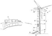
图1是示意性地显示根据本发明的示例性实施方式的风力涡轮机系统的透视图。Fig. 1 is a perspective view schematically showing a wind turbine system according to an exemplary embodiment of the present invention.
图2是图示根据本发明的示例性实施方式的风力涡轮机组装和管理机器人的部件的图。FIG. 2 is a diagram illustrating components of a wind turbine assembly and management robot according to an exemplary embodiment of the present invention.
图3是示意性地显示根据本发明的示例性实施方式的风力涡轮机组装和管理机器人的识别单元的示例性实施方式的透视图。FIG. 3 is a perspective view schematically showing an exemplary embodiment of a recognition unit of a wind turbine assembly and management robot according to an exemplary embodiment of the present invention.
图4是显示根据本发明的示例性实施方式的风力涡轮机组装和管理机器人的工作单元的示例性实施方式的剖视图。4 is a sectional view showing an exemplary embodiment of a work cell of a wind turbine assembly and management robot according to an exemplary embodiment of the present invention.
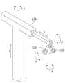
图5是图示根据本发明的示例性实施方式的风力涡轮机组装和管理机器人的操作单元的操作方法的视图。FIG. 5 is a view illustrating an operation method of an operation unit of a wind turbine assembly and management robot according to an exemplary embodiment of the present invention.
图6是显示根据本发明的示例性实施方式的风力涡轮机组装和管理机器人的操作单元的示例性实施方式的示意图。FIG. 6 is a schematic diagram showing an exemplary embodiment of an operation unit of the wind turbine assembly and management robot according to the exemplary embodiment of the present invention.
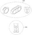
图7到图9是显示根据本发明的示例性实施方式的风力涡轮机组装和管理机器人的移动单元的各种示例性实施方式的示意图。7 to 9 are schematic diagrams showing various exemplary embodiments of the mobile unit of the wind turbine assembly and management robot according to the exemplary embodiment of the present invention.
图10是显示根据本发明的示例性实施方式的风力涡轮机组装和管理机器人的工作和移动方法的示意图。FIG. 10 is a schematic diagram showing a working and moving method of a wind turbine assembly and management robot according to an exemplary embodiment of the present invention.
图11是显示根据本发明的示例性实施方式的风力涡轮机组装和管理机器人的控制单元的配置的示意图。FIG. 11 is a schematic diagram showing a configuration of a control unit of a wind turbine assembly and management robot according to an exemplary embodiment of the present invention.
图12是显示在失去根据本发明的示例性实施方式的风力涡轮机组装和管理机器人的位置时如何控制该机器人的示意图。FIG. 12 is a schematic diagram showing how to control the wind turbine assembly and management robot according to the exemplary embodiment of the present invention when the robot loses its position.
图13是显示根据本发明的示例性实施方式的风力涡轮机组装和管理机器人的工作状态的方案视图。FIG. 13 is a schematic view showing a working state of a wind turbine assembly and management robot according to an exemplary embodiment of the present invention.
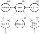
图14是显示根据本发明的示例性实施方式的风力涡轮机组装和管理机器人的状态的详细方案视图。FIG. 14 is a detailed schematic view showing a state of a wind turbine assembly and management robot according to an exemplary embodiment of the present invention.
发明的最佳模式best mode of invention
本发明的方面可以提供一种风力涡轮机组装和管理机器人,该风力涡轮机组装和管理机器人可以包括:识别单元,其识别3D空间且获得并传送图像信息;工作单元,其螺栓连接塔节的法兰联接部分;操作单元,其移动螺栓、螺母及工作单元并螺栓连接螺栓、螺母及工作单元;移动单元,其沿着法兰联接部分水平地移动或使用风力涡轮机中的梯或升降机移动;控制单元,其控制识别单元、操作单元和移动单元;以及通信单元,其与远程控制系统通信。Aspects of the present invention may provide a wind turbine assembly and management robot, which may include: a recognition unit that recognizes a 3D space and obtains and transmits image information; a work unit that bolts to the flanges of the tower sections Coupling part; operating unit that moves and bolts bolts, nuts and working unit; moving unit that moves horizontally along the flanged joint or using a ladder or lift in a wind turbine; control unit , which controls the identification unit, the operation unit, and the mobile unit; and a communication unit, which communicates with the remote control system.
操作单元可以附接到工作单元或移动单元/与工作单元或移动单元可分开。The operating unit may be attachable/detachable to/from the work unit or the mobile unit.
操作单元可以包括操纵器和联接部分,该联接部分可以附接到工作单元或移动单元/与工作单元或移动单元可分开。The operation unit may include a manipulator and a coupling portion which may be attached/detachable to/from the work unit or the mobile unit.
联接部分可以包括抓握部和联接单元,联接单元可以附接到抓握部/与抓握部可分开且接纳并固定工作单元或移动单元。The coupling part may include a grip part and a coupling unit which may be attached/detachable to the grip part and which receives and fixes the working unit or the moving unit.
操纵器是具有六个或更多的自由度的操纵器,且操作单元可以包括操纵器的至少两个或更多的件。The manipulator is a manipulator having six or more degrees of freedom, and the operation unit may include at least two or more pieces of the manipulator.
识别单元可以包括操纵器、照相机和传感器。The recognition unit may include manipulators, cameras and sensors.
工作单元可以是螺母驱动器或焊接驱动器。The work unit can be a nut driver or a weld driver.
移动单元可以包括选自可沿着梯栏杆或扶手移动的移动构件、可将法兰联接部分用作引导栏杆的移动构件以及可进入/离开升降机的移动构件中的至少一个。The moving unit may include at least one selected from a moving member movable along a ladder rail or handrail, a moving member capable of using the flange coupling portion as a guide rail, and a moving member capable of entering/exiting the elevator.
控制单元可以包括存储器、3D空间模型产生器、机器人定位器及机器人处理器,存储器存储内部/外部涡轮机设计值和机器人设计值,3D空间模型产生器使用识别单元的所识别的值而产生3D空间模型测量值,机器人定位器通过比较设计值和测量值来计算机器人的当前位置值,机器人处理器基于当前位置值移动机器人来执行所需的工作。The control unit may include a memory, a 3D space model generator, a robot positioner, and a robot processor, the memory stores internal/external turbine design values and robot design values, and the 3D space model generator uses the recognized values of the recognition unit to generate a 3D space Model measurements, the robot positioner calculates the robot's current position value by comparing the design value with the measured value, and the robot processor moves the robot to perform the required work based on the current position value.
当机器人定位器确定失去位置时,机器人处理器通过增加识别单元的识别的量而获得再次识别值,机器人定位器基于该再次识别值确定当前位置,并且机器人处理器可以使机器人的当前状态返回到之前状态。When the robot locator determines that it has lost its position, the robot processor obtains a re-identification value by increasing the amount of identification of the identification unit, the robot locator determines the current position based on the re-identification value, and the robot processor can return the current state of the robot to previous state.
本发明的另一个方面可以包括风力涡轮机、风力涡轮机组装和管理机器人以及远程控制系统。Another aspect of the invention may include a wind turbine, a wind turbine assembly and management robot, and a remote control system.
其它的示例性实施方式的细节包括在本发明的示例性实施方式和相应的附图中。Details of other exemplary embodiments are included in the exemplary embodiments of the invention and the corresponding drawings.
实施方式的详细描述Detailed description of the implementation
通过参考以下参考附图详细描述的示例性实施方式,本发明的益处和特征及实现本发明的益处和特征的方法将是清楚的。然而,本发明不限于以下描述的且以各种方式实现的示例性实施方式,提供示例性实施方式以完成本发明且使得本发明的范围对于本领域的技术人员来说是清楚的,且本发明仅由权利要求所描述的范围来界定。因此,众所周知的技术将不在一些示例性实施方式中详细地描述,以避免对本发明的不清楚解释。The benefits and features of the present invention and a method of achieving the benefits and features of the present invention will be apparent by referring to the following exemplary embodiments described in detail with reference to the accompanying drawings. However, the present invention is not limited to the exemplary embodiments described below and implemented in various ways, the exemplary embodiments are provided to accomplish the present invention and to make the scope of the present invention clear to those skilled in the art, and this The invention is limited only by the scope described in the claims. Therefore, well-known techniques will not be described in detail in some example embodiments in order to avoid obscuring the explanation of the invention.
图1是示意性地显示根据本发明的示例性实施方式的风力涡轮机系统的透视图。参考图1,风力涡轮机系统包括风力涡轮机1和远程控制系统8。风力涡轮机1包括塔2、安装在塔2上的机舱3、固定在机舱3上的转子4以及风力涡轮机组装和管理机器人7。风力涡轮机组装和管理机器人7和远程控制系统8被实施为使得无线通信是可能的。Fig. 1 is a perspective view schematically showing a wind turbine system according to an exemplary embodiment of the present invention. Referring to FIG. 1 , a wind turbine system includes a wind turbine 1 and a
在图1中,转子4由覆盖转子轮毂(未显示)的自旋体5和安装在转子轮毂上的转子叶片6构成。尽管在附图中例示了三个转子叶片6,但是可以包括三个或者更多或更少的转子叶片6。通过容易地旋转转子4,转子叶片6将来自于风的动能转化成机械能,并且最终转化成电能。更详细地,当风撞击转子叶片6时,转子4围绕旋转轴10旋转且将来自于风的动能转化成机械能。由于风易于改变方向,因此需要控制以使转子叶片6大体上面对风。换而言之,可能通过转动机舱3来最大化撞击转子叶片6的风的量,使得风的方向大体上平行于旋转轴10,或者使得转子叶片6以相同的方式或分别地垂直于其纵轴12,即垂直于转子4的旋转轴10且围绕旋转轴线12倾斜,旋转轴线12是与塔2的纵轴是大体上相同的轴线。In FIG. 1 , a rotor 4 is composed of a spin body 5 covering a rotor hub (not shown) and rotor blades 6 mounted on the rotor hub. Although three rotor blades 6 are illustrated in the drawings, three or more or less rotor blades 6 may be included. By easily rotating the rotor 4, the rotor blades 6 convert kinetic energy from the wind into mechanical energy, and eventually into electrical energy. In more detail, when wind strikes the rotor blades 6, the rotor 4 rotates around the rotation axis 10 and converts the kinetic energy from the wind into mechanical energy. Since the wind tends to change direction, control is required so that the rotor blades 6 generally face the wind. In other words, it is possible to maximize the amount of wind hitting the rotor blades 6 by turning the
机舱3接纳电力发电机及相关部件。因此,通过电力发电机(未显示)将通过转子4传输的机械能转化成电能。机舱3接纳电力发电机及相关部件,并且包括用于提供空间的平台3,使得工人或机器人7在执行安装、组装及维护的各项工作(在下文中,称为组装和管理工作)时可以站立。The
塔2通常可以通过堆叠和组装多个闭合环类型的塔节22来制造,塔节22通过滚扎弧形钢板且然后固定钢板的端部来形成。塔2包括用于从地面11进入塔2的入口24。使用外部梯26使得从地面11移动到入口24是可能的。可以在塔2内安装内部梯28和升降机29,使得工人或机器人7在执行关于风力涡轮机1的组装和管理工作时移动。另外,类似于机舱3,多个平台20可以布置在塔2内,以提供空间,使得工人在执行各项组装和管理工作时可以站立。The tower 2 can generally be manufactured by stacking and assembling a plurality of closed ring
图2是图示根据本发明的示例性实施方式的风力涡轮机管理机器人7的部件的图。Fig. 2 is a diagram illustrating components of a wind
根据本发明的示例性实施方式的风力涡轮机组装和管理机器人7包括识别单元100、工作单元200、操作单元300、移动单元400、通信单元500、控制单元600及功率单元700。The wind turbine assembly and
识别单元100识别3D空间并支持沿着移动路径从当前位置到目标位置的移动。识别单元100的结果可用于产生管理机器人7的移动路径和操作路径。另外,识别单元100还可用于监控风力涡轮机1中的状态。作为监测内部状态的示例,可以包括获得用于视觉上检查螺栓是紧固还是松开的图像信息以及通过通信单元500将信息传递到远程控制系统8。The
工作单元200是用于在工作对象上执行预定工作的工具。例如,工作单元200可以是用于紧固螺栓和螺母的工具。The
操作单元300起到将螺栓、螺母或操作单元200移动或固定到期望位置的作用。The
操作单元400是使得管理机器人7成为移动机器人7的一部分。移动单元400接收来自于功率单元700的功率,且使得机器人7能够在控制单元600的控制下从起始位置移动到期望位置。The operation unit 400 is what makes the management robot 7 a part of the
通信单元500允许与远程控制系统8的有线/无线通信或者与升降机29的无线通信单元的无线通信。The communication unit 500 allows wired/wireless communication with the
根据来自于远程控制系统8的指令,控制单元600自动地控制识别单元100、工作单元200、操作单元300、移动单元400以及通信单元500的部件,或者控制机器人7。The control unit 600 automatically controls components of the
功率单元700是将功率供给到识别单元100、工作单元200、操作单元300、移动单元400、通信单元500和控制单元600的部件的部分。功率单元700可以通过风力涡轮机1中的插座来充电。The power unit 700 is a part that supplies power to components of the
通信单元500、控制单元600及功率单元700可以布置在机器人7的主体800中且从外部是不可见的。另外,如果需要,则工作单元200和移动单元400可以被接纳在主体800中且结合操作单元300来使用。The communication unit 500, the control unit 600 and the power unit 700 may be arranged in the
图3是显示识别单元100的示例性实施方式的示意性透视图。FIG. 3 is a schematic perspective view showing an exemplary embodiment of the
识别单元100可以包括照相机110、传感器120及操纵器130。照相机110可用于监控塔1中的状态并将3D图像信息传送到远程控制系统8。传感器120可以包括扭矩传感器。扭矩传感器可用于测量是否用恒定的转矩执行用于组装塔节22的螺栓连接。除了扭矩传感器以外,传感器120还可以包括压力传感器、位置传感器、光学传感器以及红外传感器。当在螺栓连接中施加压力时,压力传感器还可以用于测量是否施加了恒定的压力。作为位置传感器,可以使用电位计、编码器、线性差动变压器及旋转变压器,并且测量机器人7的动作和移动。光学传感器或红外传感器可以用于在获得关于环境的信息并且开始与其它对象接触之前确定是否接近机器人7。可以设置操纵器130,以便以期望的姿势识别塔1中的期望空间。因此,优选的是,操纵器130是具有六个或更多的自由度的操纵器。三个自由度为旋转运动(a)、径向运动(b)以及垂直运动(c)。另外的三个自由度是倾斜(d)、偏转(e)以及滚动(f)。根据实现机器人7的方式,可以不设置特定的操纵器130。The
图4是显示工作单元200的示例性实施方式的剖视图。FIG. 4 is a cross-sectional view showing an exemplary embodiment of the working
工作单元200是用于在工作对象上执行预定工作的工具。工作的类型可以分类为:不需要大的力但旋转速度应该高的情况以及旋转速度不高但需要大的力的情况。例如,工作单元200可以是用于螺栓连接塔节22的螺母驱动器210或者可以是焊接驱动器220。优选的是,螺母驱动器210具有至少两个或更多的自由度。一个自由度可以用于拉动螺栓,且其它的自由度可以用于转动螺母。参考图4,螺母驱动器210或焊接驱动器220具有头部2110和2210、主体2120和2210以及驱动单元2130和2230,头部2110和2210可以被紧固、旋转或可以焊接接触工作对象,主体2120和2210将驱动力传递到头部2110和2210且形成外观,驱动单元2130和2230向头部2110和2210产生驱动力。然而,本发明不限于此,且工作单元200可以包括根据工作类型、螺栓和螺母的各种工具。因此,优选的是,工作单元200与可分开地安装的机器人7一起移动。例如,工作单元200可以在移动中被接纳在机器人主体800中,且然后结合工作单元300来执行螺栓连接方面的工作。The
图5是显示操作单元300的操作方法的视图。操作单元300使螺栓302和螺母304移动到法兰联接部分23,且然后用螺母驱动器210执行螺栓连接,螺母驱动器210是工作单元200的示例。因此,优选的是,操作单元300通过具有三个或更多的自由度,更优选地具有六个或更多的自由度的两个或更多的操纵器310来实施。需要操作单元300来控制位置和力两者。FIG. 5 is a view showing an operation method of the
如图6所示的,操作单元300还可以具有可以附接到工作单元200/可以与工作单元200分开的联接器320。联接器320是用于抓握工作对象比如螺栓或螺母或用于抓握和释放工作单元200的部分,用于诸如紧固或松开螺栓的工作。As shown in FIG. 6 , the
联接器320还可以附接到移动单元400/可以与移动单元400分开,这在下面描述。The coupler 320 is also attachable/detachable to the mobile unit 400, which is described below.
联接器320可以以第一联接机构3210或第二联接机构3220的类型来实现。第一联接机构3210可以以抓握部的类型来实现,该抓握部包括连接到操纵器310的连接部分3212和支撑指状物3214的支撑部分3216。指状物3214可以旋转和移动,且可以执行抓握,使得其可以保持且旋转/移动工作对象(螺栓、螺母或工作单元200),且然后将其放到期望位置。例如,成对地设置指状物3214,使得其通过相互靠近的移动来执行抓握,且通过相互远离的移动来执行释放。支撑部分3216起到允许指状物3214的抓握的铰链轴的作用,并且使指状物3214结合连接部分3212。连接部分3212可以附接操纵器310/可以与操纵器310分开。The coupler 320 may be implemented in the type of the
第二联接机构3220可以通过第一联接机构3210和联接单元3230的结合来实现。当第一联接机构3210抓握螺栓或螺母时,固定力不成问题,但当第一联接机构3210与工作单元200一起旋转以拧紧螺栓和螺母时,工作单元200可以与第一联接机构3210分离。因此,第二联接机构3220还可以包括联接单元3230,联接单元3230用于更加牢固且稳定地联接到工作单元200且使得工作单元200的操作更加平稳。联接单元3230的形状可以根据工作单元200的形状以各种方式来改变。例如,联接单元3230可以通过抓握件类型的第一联接机构3210的抓握和释放来附接/分开。联接单元3230形成用于接纳第一联接机构3210的空间,且可以由固定到第一联接机构3210的固定部分3232和联接到工作单元200的联接器3234构成。联接器3234具有可以接纳和固定工作单元200的形状。联接单元3230形成为使得在抓握状态中第一联接机构3210可以插入联接单元3230中/与联接单元3230分离。例如,联接单元3230可以具有开口,当第一联接机构3210被释放时,开口可以在压力下开始与联接单元3230接触,并且在第一联接机构3210的抓握状态中,开口可以自由地附接到联接单元3230/与联接单元3230分开。另外,固定部分3232可以具有可接纳第一联接机构3210的具有多边形横截面的中空管形状。即,第一联接机构3210可以被分离且通过滑动而安装到固定部分3232中。操作单元300还可以结合移动单元400执行移动单元400的功能。The
图7到图9是显示移动单元400的各种示例性实施方式的示意图。7 to 9 are schematic diagrams showing various exemplary embodiments of a mobile unit 400 .
意指使机器人7移动的机构的移动单元400可以是轮或人形腿。The moving unit 400, which means a mechanism for moving the
在塔1中移动的机器人7可以以外部梯26<->塔平台20<->内部梯28或升降机29<->机舱平台20<->转子4的顺序移动。The
因此,如图7所示例的,移动单元400可以包括可以沿着外部梯26或内部梯28的栏杆或扶手移动的第一移动构件。第一移动构件可以实现为金属轮4110比如火车的轮或通过将电磁轮4114插入在塑料轮4112中而形成的复合轮4120。对于复合轮4120,可能通过控制单元600来控制施加到电磁轮4114的电磁力的大小,使得轮可以沿着梯26和28平稳地旋转。Thus, as illustrated in FIG. 7 , the mobile unit 400 may include a first mobile member movable along a rail or handrail of the
另外,如图8所示例的,移动单元400可以包括第二移动构件,第二移动构件可以在组装两个塔节22时沿着由相互接合的两个法兰联接部分23形成的环进行水平移动421。第二移动构件可以实现为将法兰联接部分23用作引导栏杆的第一滑动器4210或第二滑动器4220来。第一滑动器4210的内侧相应于法兰联接部分23的形状而形成。另外,长方形凹槽4213在第一滑动器4210的内侧上形成以接合法兰联接部分23,且多个球4215被插入长方形凹槽4213中,使得第一滑动器4210容易地沿着法兰联接部分23移动。第二滑动器4220可以包括沿着法兰联接部分23的上侧和下侧旋转的一对旋转轴承4223和穿过旋转轴承4223的中心插入的中空轴4225。螺母4227可以固定到中空轴4225的一端。In addition, as shown in FIG. 8 , the moving unit 400 may include a second moving member that can move horizontally along the ring formed by the two
另外,如图9所示例的,移动单元400可以包括可以使用平台20和30或升降机29来移动的第三移动构件。第三移动构件可以是诸如普通的轮4310或腿4320的移动构件。In addition, as illustrated in FIG. 9 , the moving unit 400 may include a third moving member that may be moved using the
同时,当移动单元使用升降机29移动时,升降机还可以包括允许通过通信单元500的无线通信呼叫的无线通信单元。因此,通信单元500和升降机29的无线通信单元可以包括无线蜂窝或蓝牙类型的无线通信模块,或者可以包括其它类型的无线通信模块。通信单元500可以通过控制单元600将用于控制升降机29的信号传送到升降机29。当升降机29的门打开时,控制单元600可以控制机器人7进入/离开升降机29。控制单元600可以实现为确定是否通过识别单元100打开/关闭升降机29的门,或者实现为通过通信单元500从升降机29接收关于升降机29的门的当前位置和开/关的信息。Meanwhile, when the mobile unit moves using the elevator 29 , the elevator may further include a wireless communication unit allowing a wireless communication call through the communication unit 500 . Therefore, the communication unit 500 and the wireless communication unit of the elevator 29 may include wireless cellular or Bluetooth type wireless communication modules, or may include other types of wireless communication modules. The communication unit 500 may transmit a signal for controlling the elevator 29 to the elevator 29 through the control unit 600 . When the door of the elevator 29 is opened, the control unit 600 may control the
移动单元400可以保持连接到机器人主体800,或者如图10所示例的,移动单元400可以被接纳在机器人主体800中且结合操作单元300。参考图10,螺母驱动器210结合操作单元300的操纵器310的第二联接机构3220并执行螺栓联接,且第一滑动器4210可以结合其它操纵器310并执行移动。The mobile unit 400 may remain connected to the
图11是显示控制单元600的配置的示意图。FIG. 11 is a schematic diagram showing the configuration of the control unit 600 .
控制单元600可以包括用于存储风力涡轮机1的3D设计图的存储器610、3D空间模型产生器620、机器人定位器630以及机器人处理器640。The control unit 600 may include a
存储器610存储风力涡轮机1的内部/外部3D空间模型设计值和在设计机器人7时确定的机器人7的设计值,比如机器人的高度、尺寸和最大输出。The
3D空间模型产生器620接收为通过识别单元100识别的3D图像识别值的立体图像和点云。使用识别单元100的识别值,3D空间模型产生器620获得机器人7的3D空间模型测量值。The 3D
机器人定位器630可以通过比较在存储器610中存储的存储值和3D空间模型产生器620的测量值来计算机器人7的当前3D位置值。The
基于机器人定位器630的当前位置值,机器人处理器640自动地控制识别单元100、工作单元200、操作单元300、移动单元400和通信单元500的部件,使得机器人7可以移动到期望位置并执行期望工作。同时,机器人处理器640根据从远程控制系统8输入的指令控制机器人7,并且将机器人7的当前状态和工作结果输出并传送到远程控制系统8。使用测量值比如通过识别单元100的传感器110测量的机器人7的特定部分的加速度和角加速度以及存储在存储器610中的机器人7的设计值,机器人处理器640控制机器人7,并且控制电动机输出。Based on the current position value of the
同时,机器人处理器640可以确定机器人7由于各种原因而处于位置失去状态1200。在图12中示例了在该情况下如何控制机器人7。参考图12,机器人处理器640不能估计机器人7的当前位置时的状态为位置失去状态1200。由于各种原因,可能在机器人7移动时产生暂时的位置失去。在这种情况下,机器人处理器640使得机器人7停止,且通过增加识别的量,使得识别单元100再次识别当前位置。当机器人定位器630基于再次识别值找到当前位置时,机器人处理器640使得机器人继续工作。例如,基于图12中的位置状态图,机器人处理器640可以使得机器人从当前状态移动到之前状态并继续工作。可优选的是,使机器人移动到之前状态并使得机器人继续工作,以便补充由于位置失去而造成的工作不完整。Meanwhile, the
机器人7可以以外部梯26<->塔平台20<->梯28或升降机29<->机舱平台20<->转子4的顺序移动。例如,当确定位置失去状态1200时,机器人位置识别器530再次识别当前位置。因此,当确定当前位置处于梯28或升降器29处时,机器人7移动到为之前状态的塔平台20并继续工作。The
图13是显示机器人工作状态的方案视图。机器人的基本状态是备用状态1300,且远程控制1310和自控制工作1320的两种工作状态是可能的。Fig. 13 is a scheme view showing the working state of the robot. The basic state of the robot is the
图14显示了以自控制工作1320的机器人状态的示例性详细方案视图。作为自控制工作1320的类型,可以存在功率连接工作1410、监控工作1420、移动工作1430、螺栓连接工作1440和其它工作1450。对于需要大的力或扭矩的工作比如螺栓连接,仅使用在机器人7中充电的能量,也许不可能执行功率连接工作1410。除了通过使机器人7连接到风力涡轮机1中的插座来充电以外,可以使用用于工作的能量。作为定期地监控风力涡轮机1的状态的工作的监控工作1420允许通过识别各种主要位置即被监控位置的高分辨率的图像且然后将图像传送到远程位置来进行定期监控。螺栓连接工作1440移动到需要螺栓连接的位置,且然后执行螺栓连接工作,或者当已经完成螺栓连接时,其检查螺栓连接是否松开,且然后在螺栓连接松开时执行再次紧固。其它工作1450可以以程序的类型传送到机器人7,且可以应用可通过机器人7执行的不同于功率连接工作1410、监控工作1420、移动工作1430和螺栓连接工作1440的任何自控制工作。FIG. 14 shows an exemplary detailed scenario view of a robot state working 1320 in self-control. As types of self-control work 1320 there may be
作为本发明的示例提供的以上参考的附图及本发明的详细描述是用来解释本发明的,而不限制在权利要求中描述的本发明的含义或范围。因此,本领域的技术人员应理解,各种修改和其它等价的示例性实施方式可以是可能的。因此,本发明的实际技术保护范围应由在权利要求中描述的精神来确定。The above-referenced drawings and the detailed description of the present invention provided as examples of the present invention are for explaining the present invention, and do not limit the meaning or scope of the present invention described in the claims. Therefore, it will be appreciated by those skilled in the art that various modifications and other equivalent exemplary embodiments may be possible. Therefore, the actual technical protection scope of the present invention should be determined by the spirit described in the claims.
工业实用性Industrial Applicability
根据本发明的示例性实施方式的风力涡轮机组装和管理机器人可以应用到可装备有风力涡轮机的风车、风力涡轮机塔、风力发电机或风力发电站。The wind turbine assembly and management robot according to the exemplary embodiment of the present invention may be applied to a windmill, a wind turbine tower, a wind generator, or a wind power station which may be equipped with a wind turbine.
另外,根据本发明的示例性实施方式的风力涡轮机系统可以应用到可以远程地控制风车、风力涡轮机塔、风力发电机或风力发电站的控制系统。In addition, the wind turbine system according to the exemplary embodiment of the present invention may be applied to a control system that can remotely control a windmill, a wind turbine tower, a wind generator, or a wind power plant.
具体地,本发明的风力涡轮机组装和管理机器人以及包含本发明的风力涡轮机组装和管理机器人的风力涡轮机系统可以用于在安装风力涡轮机之前的安装准备,或者用于安装之后的维护和监控。Specifically, the wind turbine assembly and management robot of the present invention and the wind turbine system including the wind turbine assembly and management robot of the present invention may be used for installation preparation before installation of a wind turbine, or for maintenance and monitoring after installation.
Claims (20)
Translated fromChineseApplications Claiming Priority (3)
| Application Number | Priority Date | Filing Date | Title |
|---|---|---|---|
| KR10-2010-0129034 | 2010-12-16 | ||
| KR1020100129034AKR101194576B1 (en) | 2010-12-16 | 2010-12-16 | Wind turbine assembly and management robot and wind turbine including the same |
| PCT/KR2011/005662WO2012081793A1 (en) | 2010-12-16 | 2011-08-01 | Wind turbine assembly and management robot and wind turbine system including same |
Publications (2)
| Publication Number | Publication Date |
|---|---|
| CN103534068Atrue CN103534068A (en) | 2014-01-22 |
| CN103534068B CN103534068B (en) | 2015-09-30 |
Family
ID=46244868
Family Applications (1)
| Application Number | Title | Priority Date | Filing Date |
|---|---|---|---|
| CN201180067181.4AActiveCN103534068B (en) | 2010-12-16 | 2011-08-01 | Wind turbine assembly and management robot and wind turbine system incorporating it |
Country Status (6)
| Country | Link |
|---|---|
| US (1) | US20130289769A1 (en) |
| EP (1) | EP2653273A4 (en) |
| JP (1) | JP5822409B2 (en) |
| KR (1) | KR101194576B1 (en) |
| CN (1) | CN103534068B (en) |
| WO (1) | WO2012081793A1 (en) |
Cited By (3)
| Publication number | Priority date | Publication date | Assignee | Title |
|---|---|---|---|---|
| CN106144842A (en)* | 2015-03-26 | 2016-11-23 | 上海东锐风电技术有限公司 | For the shuttle unit of wind-driven generator and the wind-driven generator including it |
| CN108843515A (en)* | 2018-06-19 | 2018-11-20 | 湖南工程学院 | Wind power installation alignment device |
| CN113966261A (en)* | 2019-04-18 | 2022-01-21 | 西门子歌美飒可再生能源公司 | Automatic Bolt Tensioning Robot |
Families Citing this family (17)
| Publication number | Priority date | Publication date | Assignee | Title |
|---|---|---|---|---|
| DK2607685T3 (en)* | 2011-12-21 | 2014-05-19 | Kenneth Johst | Robot for mounting and fastening screws for wind turbines |
| CA2875266C (en) | 2012-06-18 | 2022-01-11 | Collineo Inc. | Remote visual inspection system and method |
| KR101379724B1 (en)* | 2012-06-27 | 2014-03-28 | 삼성중공업 주식회사 | Assembly robot for windmill blade |
| US9476804B1 (en)* | 2012-11-16 | 2016-10-25 | Avanti Wind Systems, Inc. | Pneumatic drop test method and apparatus for use with lifts and work cages in wind turbine towers |
| CN103353907A (en)* | 2013-06-17 | 2013-10-16 | 沈阳华创风能有限公司 | Calculating method of ultimate strength checking of connection of flange and bolt |
| WO2015112852A1 (en)* | 2014-01-23 | 2015-07-30 | Avanti Wind Systems, Inc. | Wind turbine tower elevator disconnect apparatus, assembly and method for using same |
| US10272572B2 (en)* | 2016-06-10 | 2019-04-30 | The Boeing Company | Remotely controlling robotic platforms based on multi-modal sensory data |
| US10023250B2 (en) | 2016-06-10 | 2018-07-17 | The Boeing Company | Multi-tread vehicles and methods of operating thereof |
| US10598158B2 (en) | 2017-07-20 | 2020-03-24 | General Electric Company | System and method for removing or installing rotor blade hardware of a wind turbine |
| EP3721081B1 (en) | 2017-12-06 | 2021-10-27 | Vestas Wind Systems A/S | Automated tightening of bolts |
| EP3769904A1 (en)* | 2019-07-24 | 2021-01-27 | Siemens Gamesa Renewable Energy A/S | Automated bolt tensioning robot |
| CN114008320B (en) | 2019-05-21 | 2023-10-13 | 维斯塔斯风力系统有限公司 | Method for erecting a wind turbine tower using studs |
| EP3832132B1 (en) | 2019-12-06 | 2023-06-07 | Wobben Properties GmbH | Mobile maintenance device, movable mounting device and method |
| CN111706469A (en)* | 2020-06-29 | 2020-09-25 | 江苏灌创能源科技有限公司 | New energy wind power generation device |
| NO346590B1 (en)* | 2020-09-18 | 2022-10-17 | Fred Olsen Ocean Ltd | Wind turbine with floating foundation |
| JP7581174B2 (en)* | 2021-11-12 | 2024-11-12 | 株式会社東芝 | Wind turbine inspection device, method, and program |
| DK202330131A1 (en)* | 2023-07-24 | 2025-03-17 | Notus Wind Aps | Service robot for wind turbines and navigation method thereof |
Citations (4)
| Publication number | Priority date | Publication date | Assignee | Title |
|---|---|---|---|---|
| JPH1034570A (en)* | 1996-07-19 | 1998-02-10 | Fujitsu Ltd | Robot remote control system |
| JP2000153416A (en)* | 1998-11-18 | 2000-06-06 | Halla Aircon Co Ltd | Heat exchanger assembly equipment |
| CN1743144A (en)* | 2005-09-29 | 2006-03-08 | 天津理工大学 | Internet-based remote control method for robots |
| CN1771113A (en)* | 2003-06-12 | 2006-05-10 | 提姆查克股份有限公司 | Robot remote control system |
Family Cites Families (22)
| Publication number | Priority date | Publication date | Assignee | Title |
|---|---|---|---|---|
| JPS63251815A (en)* | 1987-04-08 | 1988-10-19 | Toyota Autom Loom Works Ltd | Trackless unmanned vehicle |
| FR2625936A1 (en)* | 1988-01-14 | 1989-07-21 | Hispano Suiza Sa | METHOD FOR SETTING UP A TOOL HOLDER ROBOT FOR INTERVENTIONS IN HUMAN HOSTILE ENVIRONMENTS |
| US5318254A (en)* | 1991-06-28 | 1994-06-07 | Conceptual Solutions, Inc. | Aircraft maintenance robot |
| US5265129A (en)* | 1992-04-08 | 1993-11-23 | R. Brooks Associates, Inc. | Support plate inspection device |
| DE4336142A1 (en)* | 1993-10-22 | 1995-04-27 | Pilz Technologie Gmbh | Facade construction as well as work elevator and method for its assembly |
| JPH08262178A (en)* | 1995-03-23 | 1996-10-11 | Tokyo Electric Power Co Inc:The | Labor saving device for regular inspection work |
| JPH09127286A (en)* | 1995-11-02 | 1997-05-16 | Toshiba Corp | Inspection and repair device and method for nuclear power plant |
| FR2785713B1 (en)* | 1998-11-10 | 2000-12-08 | Commissariat Energie Atomique | CONTROL SYSTEM FOR LIFT AND TELEMANIPULATION UNITS PLACED IN CONFINED ENCLOSURES |
| CA2344125C (en)* | 1999-03-10 | 2005-01-18 | Mitsubishi Heavy Industries, Ltd. | Working robot |
| JP3968501B2 (en)* | 2001-11-30 | 2007-08-29 | ソニー株式会社 | Robot self-position identification system and self-position identification method |
| JP3801514B2 (en)* | 2002-02-08 | 2006-07-26 | 三菱重工業株式会社 | Maintenance inspection system, maintenance inspection method, and IC tag |
| JP3764713B2 (en)* | 2002-09-13 | 2006-04-12 | 三菱重工業株式会社 | Maintenance inspection system and maintenance inspection method |
| US7908923B2 (en)* | 2006-12-07 | 2011-03-22 | Siemens Aktiengesellschaft | Method of non-destructively testing a work piece and non-destructive testing arrangement |
| DE102008016925A1 (en)* | 2008-04-02 | 2009-10-08 | Wobben, Aloys | Wind turbine with several construction sections |
| JP5281366B2 (en)* | 2008-11-05 | 2013-09-04 | 三菱重工業株式会社 | Bolt fastening device |
| US20100332016A1 (en)* | 2009-06-25 | 2010-12-30 | Abrams Charles A | Vision guided real time locating and trimming of flash |
| US20110033254A1 (en)* | 2009-08-06 | 2011-02-10 | Kmt Robotic Solutions, Inc. | System And Method Of Locating Relative Positions Of Objects |
| KR20110026211A (en)* | 2009-09-07 | 2011-03-15 | 삼성전자주식회사 | Humanoid robot |
| US8600552B2 (en)* | 2009-10-30 | 2013-12-03 | Honda Motor Co., Ltd. | Information processing method, apparatus, and computer readable medium |
| KR101225691B1 (en)* | 2011-09-02 | 2013-01-23 | 삼성중공업 주식회사 | Maintenance robot for wind power generator |
| DK2607685T3 (en)* | 2011-12-21 | 2014-05-19 | Kenneth Johst | Robot for mounting and fastening screws for wind turbines |
| JP5507595B2 (en)* | 2012-02-17 | 2014-05-28 | ファナック株式会社 | Article assembling apparatus using robot |
- 2010
- 2010-12-16KRKR1020100129034Apatent/KR101194576B1/ennot_activeExpired - Fee Related
- 2011
- 2011-08-01WOPCT/KR2011/005662patent/WO2012081793A1/enactiveApplication Filing
- 2011-08-01EPEP11849590.2Apatent/EP2653273A4/ennot_activeWithdrawn
- 2011-08-01USUS13/994,684patent/US20130289769A1/ennot_activeAbandoned
- 2011-08-01JPJP2013540880Apatent/JP5822409B2/enactiveActive
- 2011-08-01CNCN201180067181.4Apatent/CN103534068B/enactiveActive
Patent Citations (4)
| Publication number | Priority date | Publication date | Assignee | Title |
|---|---|---|---|---|
| JPH1034570A (en)* | 1996-07-19 | 1998-02-10 | Fujitsu Ltd | Robot remote control system |
| JP2000153416A (en)* | 1998-11-18 | 2000-06-06 | Halla Aircon Co Ltd | Heat exchanger assembly equipment |
| CN1771113A (en)* | 2003-06-12 | 2006-05-10 | 提姆查克股份有限公司 | Robot remote control system |
| CN1743144A (en)* | 2005-09-29 | 2006-03-08 | 天津理工大学 | Internet-based remote control method for robots |
Cited By (4)
| Publication number | Priority date | Publication date | Assignee | Title |
|---|---|---|---|---|
| CN106144842A (en)* | 2015-03-26 | 2016-11-23 | 上海东锐风电技术有限公司 | For the shuttle unit of wind-driven generator and the wind-driven generator including it |
| CN108843515A (en)* | 2018-06-19 | 2018-11-20 | 湖南工程学院 | Wind power installation alignment device |
| CN113966261A (en)* | 2019-04-18 | 2022-01-21 | 西门子歌美飒可再生能源公司 | Automatic Bolt Tensioning Robot |
| US12122003B2 (en) | 2019-04-18 | 2024-10-22 | Siemens Gamesa Renewable Energy A/S | Automated bolt tensioning robot |
Also Published As
| Publication number | Publication date |
|---|---|
| WO2012081793A1 (en) | 2012-06-21 |
| JP5822409B2 (en) | 2015-11-24 |
| EP2653273A4 (en) | 2017-12-27 |
| EP2653273A1 (en) | 2013-10-23 |
| US20130289769A1 (en) | 2013-10-31 |
| KR20120067562A (en) | 2012-06-26 |
| CN103534068B (en) | 2015-09-30 |
| JP2014506968A (en) | 2014-03-20 |
| KR101194576B1 (en) | 2012-10-25 |
Similar Documents
| Publication | Publication Date | Title |
|---|---|---|
| CN103534068B (en) | Wind turbine assembly and management robot and wind turbine system incorporating it | |
| EP2832988A1 (en) | Method and apparatus for handling a rotor blade | |
| EP3163071A1 (en) | Automatic tightening of bolts | |
| CN107059611B (en) | Multi-rotor-wing inhaul cable detection robot and inhaul cable detection method thereof | |
| CN108161899A (en) | A kind of biped climbs crusing robot | |
| US20210239096A1 (en) | Wind power generation apparatus having tower crane structure | |
| CN116197948A (en) | Wind power tower detection robot platform and pose control method thereof | |
| CN202966472U (en) | Intelligent electromagnetic climbing robot | |
| Lim et al. | The inchworm type blade inspection robot system | |
| Faria et al. | ROSI: a mobile robot for inspection of belt conveyor | |
| CN206623081U (en) | A kind of hot line robot operation monitoring system | |
| EP2617988B1 (en) | Manual lifting tool for wind turbines | |
| US20180313334A1 (en) | Hoistable platform assembly within a nacelle of a wind turbine | |
| KR101853554B1 (en) | Moving apparatus for yaw brake | |
| CN109372704A (en) | The analysis of generating set intelligent trouble diagnosis and O&M operation machine system and generating field | |
| KR101302979B1 (en) | Fastening condition monitoring apparatus and monitoring method of the same | |
| Guo et al. | The utility model relates to a cleaning mechanical arm applicable to a high voltage insulator cleaning robot | |
| Han et al. | Robot system and fastening force control for sealing blocking plates of steam generator | |
| EP4306798A1 (en) | Cabins and methods for wind turbine maintenance | |
| CN114012748A (en) | Transmission tower humanoid climbing robot | |
| US20250091167A1 (en) | Gantry system for manufacturing a wind turbine blade and method for manufacturing a wind turbine blade | |
| KR101302994B1 (en) | Maintenance system for ocean wind farm | |
| CN220549960U (en) | Climbing device and wind power tower | |
| KR101324980B1 (en) | Maintenance apparatus for blade of wind turbine and wind turbine having the same | |
| CN120664032A (en) | High-rise building climbing robot based on the principle of fire hook ladder |
Legal Events
| Date | Code | Title | Description |
|---|---|---|---|
| C06 | Publication | ||
| PB01 | Publication | ||
| C10 | Entry into substantive examination | ||
| SE01 | Entry into force of request for substantive examination | ||
| C14 | Grant of patent or utility model | ||
| GR01 | Patent grant |