CN103529454A - Multi-telescope laser ranging system and method - Google Patents
Multi-telescope laser ranging system and methodDownload PDFInfo
- Publication number
- CN103529454A CN103529454ACN201310548642.0ACN201310548642ACN103529454ACN 103529454 ACN103529454 ACN 103529454ACN 201310548642 ACN201310548642 ACN 201310548642ACN 103529454 ACN103529454 ACN 103529454A
- Authority
- CN
- China
- Prior art keywords
- laser
- telescope
- control device
- receiving
- telescopes
- Prior art date
- Legal status (The legal status is an assumption and is not a legal conclusion. Google has not performed a legal analysis and makes no representation as to the accuracy of the status listed.)
- Pending
Links
- 238000000034methodMethods0.000titleclaimsabstractdescription23
- 238000005259measurementMethods0.000claimsdescription25
- 238000002592echocardiographyMethods0.000abstractdescription20
- 238000011161developmentMethods0.000abstractdescription7
- 230000000694effectsEffects0.000abstractdescription7
- 238000001514detection methodMethods0.000description12
- 230000001360synchronised effectEffects0.000description7
- 238000010586diagramMethods0.000description6
- 238000007499fusion processingMethods0.000description6
- 238000004364calculation methodMethods0.000description5
- PEDCQBHIVMGVHV-UHFFFAOYSA-NGlycerineChemical compoundOCC(O)COPEDCQBHIVMGVHV-UHFFFAOYSA-N0.000description3
- 230000004927fusionEffects0.000description3
- 238000009826distributionMethods0.000description2
- 238000012937correctionMethods0.000description1
- 230000007812deficiencyEffects0.000description1
- 238000013461designMethods0.000description1
- 238000001914filtrationMethods0.000description1
- 238000012986modificationMethods0.000description1
- 230000004048modificationEffects0.000description1
- 238000012545processingMethods0.000description1
- 238000003672processing methodMethods0.000description1
- 230000001629suppressionEffects0.000description1
- 238000012360testing methodMethods0.000description1
- 238000002834transmittanceMethods0.000description1
Images


Classifications
- G—PHYSICS
- G01—MEASURING; TESTING
- G01S—RADIO DIRECTION-FINDING; RADIO NAVIGATION; DETERMINING DISTANCE OR VELOCITY BY USE OF RADIO WAVES; LOCATING OR PRESENCE-DETECTING BY USE OF THE REFLECTION OR RERADIATION OF RADIO WAVES; ANALOGOUS ARRANGEMENTS USING OTHER WAVES
- G01S17/00—Systems using the reflection or reradiation of electromagnetic waves other than radio waves, e.g. lidar systems
- G01S17/02—Systems using the reflection of electromagnetic waves other than radio waves
- G01S17/06—Systems determining position data of a target
- G01S17/08—Systems determining position data of a target for measuring distance only
- G01S17/10—Systems determining position data of a target for measuring distance only using transmission of interrupted, pulse-modulated waves
- G01S17/18—Systems determining position data of a target for measuring distance only using transmission of interrupted, pulse-modulated waves wherein range gates are used
- G—PHYSICS
- G01—MEASURING; TESTING
- G01C—MEASURING DISTANCES, LEVELS OR BEARINGS; SURVEYING; NAVIGATION; GYROSCOPIC INSTRUMENTS; PHOTOGRAMMETRY OR VIDEOGRAMMETRY
- G01C3/00—Measuring distances in line of sight; Optical rangefinders
- G01C3/02—Details
- G01C3/06—Use of electric means to obtain final indication
- G01C3/08—Use of electric radiation detectors
- G—PHYSICS
- G01—MEASURING; TESTING
- G01S—RADIO DIRECTION-FINDING; RADIO NAVIGATION; DETERMINING DISTANCE OR VELOCITY BY USE OF RADIO WAVES; LOCATING OR PRESENCE-DETECTING BY USE OF THE REFLECTION OR RERADIATION OF RADIO WAVES; ANALOGOUS ARRANGEMENTS USING OTHER WAVES
- G01S7/00—Details of systems according to groups G01S13/00, G01S15/00, G01S17/00
- G01S7/48—Details of systems according to groups G01S13/00, G01S15/00, G01S17/00 of systems according to group G01S17/00
- G01S7/481—Constructional features, e.g. arrangements of optical elements
- G01S7/4816—Constructional features, e.g. arrangements of optical elements of receivers alone
- G—PHYSICS
- G01—MEASURING; TESTING
- G01S—RADIO DIRECTION-FINDING; RADIO NAVIGATION; DETERMINING DISTANCE OR VELOCITY BY USE OF RADIO WAVES; LOCATING OR PRESENCE-DETECTING BY USE OF THE REFLECTION OR RERADIATION OF RADIO WAVES; ANALOGOUS ARRANGEMENTS USING OTHER WAVES
- G01S7/00—Details of systems according to groups G01S13/00, G01S15/00, G01S17/00
- G01S7/48—Details of systems according to groups G01S13/00, G01S15/00, G01S17/00 of systems according to group G01S17/00
- G01S7/483—Details of pulse systems
- G01S7/486—Receivers
- G01S7/487—Extracting wanted echo signals, e.g. pulse detection
- G01S7/4873—Extracting wanted echo signals, e.g. pulse detection by deriving and controlling a threshold value
Landscapes
- Engineering & Computer Science (AREA)
- Physics & Mathematics (AREA)
- General Physics & Mathematics (AREA)
- Radar, Positioning & Navigation (AREA)
- Remote Sensing (AREA)
- Computer Networks & Wireless Communication (AREA)
- Electromagnetism (AREA)
- Optical Radar Systems And Details Thereof (AREA)
Abstract
Translated fromChinese
Description
Translated fromChinese技术领域technical field
本发明涉及空间目标激光测距技术,尤其涉及一种多望远镜激光测距系统及其方法。The invention relates to space target laser ranging technology, in particular to a multi-telescope laser ranging system and a method thereof.
背景技术Background technique
卫星激光测距(Satellite Laser Ranging,SLR)是指地面站向空间目标发射激光脉冲信号,并采用一定口径的望远镜接收激光回波,从而通过记录该激光信号从地面站到空间目标的往返飞行时间,获得空间目标的精确距离。由于激光具有单色性好、方向性强、抗干扰及高亮度等特点,SLR技术已成为空间目标测量中精度最高的技术,广泛应用在航天器精密定轨、地球自转参数确定、全球地球参考框架建立维护等领域。随着该技术应用领域的扩展,测量范围从数百公里到数万公里的卫星,最远达到月球甚至行星际,测量目标类型也从带有角反射器的合作目标卫星发展到表面漫反射的非合作空间目标,然而,由于激光回波强度随距离四次方衰减,因此对望远镜的口径大小提出了要求。Satellite laser ranging (Satellite Laser Ranging, SLR) means that the ground station emits a laser pulse signal to the space target, and uses a telescope with a certain caliber to receive the laser echo, so as to record the round-trip flight time of the laser signal from the ground station to the space target. , to obtain the precise distance of the space target. Because the laser has the characteristics of good monochromaticity, strong directionality, anti-interference and high brightness, SLR technology has become the technology with the highest precision in space target measurement, and is widely used in precise orbit determination of spacecraft, determination of earth rotation parameters, and global earth reference. The framework builds and maintains other areas. With the expansion of the application field of this technology, the measurement range is from hundreds of kilometers to tens of thousands of kilometers of satellites, the farthest reaches the moon or even interplanetary, and the measurement target type has also developed from cooperative target satellites with corner reflectors to surface diffuse reflectors. Non-cooperative space targets, however, impose requirements on the aperture size of the telescope because the intensity of the laser echo decays with the fourth power of distance.
众所周知,单台望远镜口径的增大,不仅需要面临大规模的支承结构以及大口径镜片的研制问题,还需承担随口径2.5~2.7次方指数增加的研制成本负担。常用的空间目标激光测距方法普遍采用单台望远镜接收的模式,受限于技术水平和研制成本,所使用的望远镜接收口径不可能太大,因此这种模式的激光测距方法探测能力有限。目前,这种模式的激光测距对于合作目标的最远探测距离为月球,即激光测月,由于单台望远镜接收的回波微弱,目前国际上50多个激光测距站仅3个可开展激光测月,均使用1.5m以上口径的望远镜,以美国阿帕奇天文台的3.5m口径为最大,且全部位于望远镜研制技术先进、经济发达的欧美国家。可以预期,对于更远的探测距离或更微弱的回波强度,采用这种单台望远镜接收模式的激光测距方法将很难得到推广和应用。As we all know, the increase of the aperture of a single telescope not only needs to face the problem of large-scale support structure and the development of large-aperture lenses, but also needs to bear the burden of development costs that increase exponentially with the aperture of 2.5 to 2.7. The commonly used laser ranging method for space targets generally adopts the mode of receiving by a single telescope. Due to the technical level and development cost, the receiving aperture of the telescope used cannot be too large, so the detection capability of the laser ranging method in this mode is limited. At present, the farthest detection distance of this mode of laser ranging for cooperative targets is the moon, that is, laser lunar surveying. Due to the weak echo received by a single telescope, only 3 of the more than 50 laser ranging stations in the world can carry out Laser moon surveys all use telescopes with an aperture of 1.5m or more, the largest being the 3.5m aperture of the Apache Observatory in the United States, and all of them are located in European and American countries with advanced telescope development technology and developed economies. It can be expected that for a longer detection distance or a weaker echo intensity, it will be difficult to popularize and apply the laser ranging method using this single-telescope receiving mode.
发明内容Contents of the invention
针对上述现有技术的不足,本发明一方面提供一种多望远镜激光测距系统,该系统能够以较低的技术难度和研制成本完成单台大口径望远镜接收激光回波的等效接收效果,实现单台望远镜对空间目标激光测距探测能力的突破。Aiming at the deficiencies of the above-mentioned prior art, the present invention provides a multi-telescope laser ranging system on the one hand, which can complete the equivalent receiving effect of a single large-aperture telescope receiving laser echoes with relatively low technical difficulty and development cost, and realize A breakthrough in the laser ranging detection capability of a single telescope for space targets.
为了解决上述技术问题,本发明采用如下技术方案:In order to solve the above technical problems, the present invention adopts the following technical solutions:
一种多望远镜激光测距系统,用于测量空间目标的距离,其特征在于,该系统包括:A multi-telescope laser ranging system for measuring the distance of a space target, characterized in that the system includes:
一激光发射器,用于向所述空间目标发射激光;a laser emitter for emitting laser light to said space target;
多台望远镜,用于接收从所述空间目标反射回的激光回波;a plurality of telescopes for receiving laser echoes reflected from said space object;
多个与所述望远镜一一对应连接的接收控制装置,用于控制相应所述望远镜接收所述激光回波,并输出所述激光回波的相应数据信息;以及A plurality of receiving control devices connected to the telescopes in one-to-one correspondence, used to control the corresponding telescopes to receive the laser echoes and output corresponding data information of the laser echoes; and
一主控制装置,其一方面控制所述激光发射器发射激光,并控制各所述接收控制装置以使它们控制相应望远镜接收所述激光回波;另一方面,其接收所述接收控制装置输出的所述激光回波的相应数据信息,并根据所述数据信息计算所述空间目标的距离。A main control device, which on the one hand controls the laser transmitter to emit laser light, and controls each of the receiving control devices so that they control the corresponding telescope to receive the laser echo; on the other hand, it receives the output of the receiving control device corresponding data information of the laser echo, and calculate the distance of the space target according to the data information.
进一步地,其中一个所述接收控制装置集成在所述主控制装置中,其余所述接收控制装置与所述主控制装置相连。Further, one of the receiving control devices is integrated in the main control device, and the other receiving control devices are connected to the main control device.
前述一种多望远镜激光测距系统,各所述接收控制装置与相应所述望远镜之间连接有一距离门控信号产生器。In the aforementioned multi-telescope laser ranging system, a distance gating signal generator is connected between each receiving control device and the corresponding telescope.
进一步地,所述距离门控信号产生器的控制精度为纳秒级。Further, the control accuracy of the range gating signal generator is nanosecond level.
进一步地,所述望远镜的跟瞄精度小于1角秒。Further, the tracking accuracy of the telescope is less than 1 arc second.
优选地,所述激光发射器的指向精度为角秒级。Preferably, the pointing accuracy of the laser emitter is at the arc-second level.
本发明另一方面提供一种利用前述多望远镜激光测距系统进行测距的方法,该方法包括以下步骤:Another aspect of the present invention provides a method for ranging by using the aforementioned multi-telescope laser ranging system, the method comprising the following steps:
步骤1,通过所述主控制装置控制所述激光发射器向所述空间目标发射激光;
步骤2,通过所述主控制装置控制各接收控制装置,以使它们分别控制相应望远镜接收激光回波;Step 2, controlling each receiving control device through the main control device, so that they respectively control the corresponding telescope to receive the laser echo;
步骤3,在接收到所述激光回波之后,通过各所述接收控制装置将相应所述望远镜接收到的所述激光回波的相应数据信息传输至所述主控制装置;
步骤4,所述主控制装置根据所述数据信息计算所述空间目标的距离。Step 4, the main control device calculates the distance of the space object according to the data information.
优选地,所述步骤2包括:Preferably, said step 2 includes:
步骤21,通过所述主控制装置计算所述激光回波预计到达各望远镜的时间并将该时间输出至相应所述接收控制装置;
步骤22,通过所述接收控制装置分别控制各望远镜在对应的所述时间接收所述激光回波。
本发明的激光测距系统通过利用多台望远镜并行接收激光回波,增大了激光回波的有效接收面积,达到了提升对空间目标激光测距探测能力的目的,在微弱激光回波信号的远距离激光测距、漫反射激光测距等领域中将具有良好应用效果。可见,本发明可以较低的技术难度和研制成本,实现相当于单台大口径望远镜对空间目标的等效激光探测能力,并具有易于推广和应用的技术优势。The laser ranging system of the present invention increases the effective receiving area of the laser echo by using multiple telescopes to receive the laser echo in parallel, and achieves the purpose of improving the laser ranging detection capability of the space target. It will have good application effects in the fields of long-distance laser ranging and diffuse reflection laser ranging. It can be seen that the present invention can achieve the equivalent laser detection capability of a single large-aperture telescope for space targets with relatively low technical difficulty and development cost, and has the technical advantage of being easy to popularize and apply.
附图说明Description of drawings
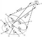
图1为本发明一个实施例的多望远镜激光测距系统的工作原理示意图;Fig. 1 is a schematic diagram of the working principle of a multi-telescope laser ranging system according to an embodiment of the present invention;
图2为本发明一个实施例的多望远镜激光测距系统的电路连接图;Fig. 2 is the circuit connection diagram of the multi-telescope laser ranging system of an embodiment of the present invention;
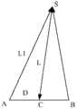
图3为本发明采用的等效距离门控值计算方法的原理示意图;Fig. 3 is the schematic diagram of the principle of the equivalent distance gating value calculation method adopted by the present invention;
图4为事件模式距离门控信号产生器的电路框图;Fig. 4 is the circuit block diagram of event mode range gating signal generator;
图5为本发明采用的数据融合处理的原理图;Fig. 5 is the schematic diagram of the data fusion processing that the present invention adopts;
图6A为使用单台望远镜对Ajisai(阿吉沙)卫星激光测量的距离残差图;Figure 6A is a distance residual map of the Ajisai (Ajisha) satellite laser measurement using a single telescope;
图6B为使用双望远镜对Ajisai卫星激光测量的距离残差图;Figure 6B is a distance residual map of the Ajisai satellite laser measurement using a pair of telescopes;
图6C为单台望远镜与双望远镜在同时段内所接收到的激光回波数统计对比图。FIG. 6C is a statistical comparison chart of the number of laser echoes received by a single telescope and a pair of telescopes in the same period.
具体实施方式Detailed ways
下面结合附图,给出本发明的较佳实施例,并予以详细描述。Below in conjunction with the drawings, preferred embodiments of the present invention are given and described in detail.
1、实现原理1. Implementation principle
空间目标激光测距雷达方程是研究空间目标激光探测能力的基本理论依据。根据激光测距雷达方程、测距系统参数和所测量空间目标截面大小等,可计算一测距系统所获得的平均激光回波光子数。其中,空间目标激光测距雷达方程(漫反射激光测距)如下:The space target laser ranging radar equation is the basic theoretical basis for studying the space target laser detection capability. According to the laser ranging radar equation, the parameters of the ranging system and the size of the measured space target section, the average number of laser echo photons obtained by a ranging system can be calculated. Among them, the space target laser ranging radar equation (diffuse reflection laser ranging) is as follows:
式(1)中,n0为望远镜接收到的平均激光回波光子数,ηq为激光探测器的探测效率,Et为激光脉冲能量,Ar为望远镜的有效接收面积,σ为空间目标散射截面,T为大气透过率参数,Tt为激光发射器的发射效率,Tr为望远镜的接收效率,α为大气衰减因子,θt为激光束发散角,R为目标距离。由于n0表征了激光测距系统的测量能力,结合式(1)可知,激光测距系统的测量能力n0与望远镜接收面积Ar成正比,因此增大望远镜接收面积Ar即可增大测距系统的测量能力。In formula (1), n0 is the average number of laser echo photons received by the telescope, ηq is the detection efficiency of the laser detector, Et is the laser pulse energy,Ar is the effective receiving area of the telescope, and σ is the space target Scattering cross section, T is the atmospheric transmittance parameter, Tt is the emission efficiency of the laser transmitter, Tr is the receiving efficiency of the telescope, α is the atmospheric attenuation factor, θt is the divergence angle of the laser beam, and R is the target distance. Since n0 represents the measurement capability of the laser ranging system, combined with formula (1), it can be seen that the measurement capability n0 of the laser ranging system is proportional to the receiving area Ar of the telescope, so increasing the receiving area Ar of the telescope can increase The measurement capability of the ranging system.
根据上述激光测距雷达方程,理论上使用N个口径为d的望远镜并行接收激光回波信号,可实现单台口径为望远镜的等效接收效果,即,采用多台小口径望远镜并行接收激光回波,可实现单台大口径望远镜的等效接收能力。According to the above laser ranging radar equation, in theory, using N telescopes with an aperture of d to receive laser echo signals in parallel can realize a single telescope with an aperture of The equivalent receiving effect of the telescope, that is, the equivalent receiving capability of a single large-aperture telescope can be achieved by using multiple small-aperture telescopes to receive laser echoes in parallel.
2、组成部分2. Components
基于上述原理,本发明的激光测距系统采用了多台望远镜,如图1和2所示,该系统具体包括以下部分:一用于向空间目标4发射激光的激光发射器3;多台用于接收从空间目标4反射回的激光回波的望远镜10,11,…,1n;多个与望远镜10,11,…,1n一一对应连接的接收控制装置20,21,…,2n,以控制相应望远镜10,11,…,1n接收激光回波,并输出所述激光回波的相应数据信息;以及一连接至激光发射器3和各接收控制装置20,21,…,2n的主控制装置,其一方面控制激光发射器3发射激光,并控制各接收控制装置20,21,…,2n以使它们在激光回波信号预计达到相应望远镜10,11,…,1n时打开各望远镜以接收激光回波,另一方面,其接收各接收控制装置20,21,…,2n输出的所述激光回波的相应数据信息,并根据这些数据信息计算空间目标4的距离。Based on the above-mentioned principle, the laser ranging system of the present invention has adopted a plurality of telescopes, as shown in Figures 1 and 2, the system specifically includes the following parts: a
在本实施例中,其中一个接收控制装置20与主控制装置集成在一起,该接收控制装置20所对应的望远镜10与激光发射器3集成在一起,作为发射端望远镜;其余望远镜11,12,…,1n作为接收端望远镜。其中,该主控制装置20通过网络与其余接收控制装置21,22,…,2n相连,以实现对各接收端望远镜11,12,…,1n的同步控制,以使它们按照各自时序开展对空间目标4的激光测距操作。各接收端望远镜11,12,…,1n所接收到的激光回波分别通过网络传输至主控制装置20,以用于对激光回波的相应数据作进一步融合处理和归算。In this embodiment, one of the
此外,各接收控制装置20,21,…,2n与相应望远镜10,11,…,1n之间分别连接有一距离门控信号产生器5,以实现对望远镜10,11,…,1n的距离门信号同步控制。In addition, each receiving
3、多望远镜的位置分布3. Position distribution of multiple telescopes
本领域的技术人员应该理解,如图1所示,各望远镜10,11,…,1n应该分布在返回激光的光斑内,以并行接收激光回波,且分别具有独立跟踪能力和激光回波信号接收探测能力。其中,对于带角反射器的合作空间目标4,根据其携带的角反射器的发散角和空间目标4到地面站点的距离,可以计算返回激光的光斑直径为几十米到公里不等,例如当空间目标4距离为2000km,反射器发散角为10角秒时,则返回激光的光斑直径为100m;对于非合作空间目标4,由于激光漫反射,则返回的激光光斑范围更大。优选地,各接收端望远镜11,12,…,1n两两对称地分布在发射端望远镜10周围。Those skilled in the art should understand that, as shown in Figure 1, the
4、多望远镜的同步跟瞄4. Synchronous tracking and aiming of multiple telescopes
在现有的单台望远镜激光测距系统中,电荷耦合器件(CCD)可同时监视激光光束及空间目标4星象,两者重合并调节至望远镜探测器视场中心即可实现激光回波接收和探测。而在本发明的多望远镜测距系统中,星象和光束指向不能同时监视,为确保可并行接收到激光回波信号,对各望远镜10,11,…,1n的指向精度及跟踪精度提出了角秒级精度要求。In the existing single-telescope laser ranging system, the charge-coupled device (CCD) can simultaneously monitor the laser beam and the four star images of the space target, and the two can be overlapped and adjusted to the center of the field of view of the telescope detector to realize the laser echo reception and detection. probing. However, in the multi-telescope ranging system of the present invention, star image and beam pointing cannot be monitored at the same time. In order to ensure that laser echo signals can be received in parallel, an angle is proposed for the pointing accuracy and tracking accuracy of each
通过跟踪恒星的方法,分别获得各望远镜10,11,…,1n的激光探测器对光信号的灵敏区域和中心位置,此中心位置将作为空间目标4指向调整的参考位置。By tracking stars, the sensitive areas and central positions of the laser detectors of the
对于可见空间目标4,通过对各望远镜10,11,…,1n的指向进行修正,可以使空间目标4位于它们的激光探测器灵敏区域的中心位置。For the visible space object 4, by correcting the pointing of each
对于处于地影中的不可见空间目标4,通过采用已知的跟踪与目标处于相同天区恒星的辅助修正方法,实时获得望远镜指向误差,再将此偏差应用到目标跟踪,实现对空间目标4的跟踪指向调整。For the invisible space target 4 in the shadow of the earth, by using the known auxiliary correction method of tracking stars in the same sky area as the target, the telescope pointing error is obtained in real time, and then this deviation is applied to the target tracking to realize the tracking of the space target 4 track pointing adjustment.
其中,各望远镜10,11,…,1n的跟瞄精度均小于1角秒。Wherein, the tracking and pointing accuracy of each
5、激光发射器5. Laser transmitter
本实施例中的激光发射器3利用CCD监视器可同时获得空间目标4星象和激光束图像,通过调整两者的相对位置,将两者图像同时移动到其激光探测器灵敏区域的中心位置,以使激光束准确指向空间目标4。其中,激光发射器3的激光指向精度优选为角秒级,以确保激光束准确击中空间目标4。The
6、操作方法6. Operation method
本发明主要通过以下步骤实现:首先,通过主控制装置20控制各望远镜10,11,…,1n独立实现对空间目标4的同步跟瞄,并控制激光发射器3在对空间目标4精确瞄准后向空间目标4发射激光;再通过主控制装置20根据目标轨道预报分别获得激光回波信号预计达到各望远镜10,11,…,1n的时间,然后应用距离门控同步技术,实现各望远镜10,11,…,1n的距离门控制,以并行接收激光回波信号;在接收到激光回波之后,通过各接收端控制装置21,22,…,2n将相应望远镜11,12,…,1n接收到的激光回波的相应数据信息传输至主控制装置20;最后,主控制装置20将这些数据信息与发射端望远镜10所接收到的激光回波数据融合归算处理(即将各望远镜10,11,…,1n所接收到的激光回波均作为发射端望远镜10所接收到的激光回波),以获取空间目标4的距离。The present invention is mainly realized through the following steps: firstly, the main control device 20 controls each telescope 10, 11, ..., 1n to independently realize the synchronous tracking and aiming of the space target 4, and controls the laser transmitter 3 to accurately aim at the space target 4 Send laser light to the space target 4; then obtain the time when the laser echo signals are expected to reach the telescopes 10, 11, ..., 1n respectively according to the target orbit forecast through the main control device 20, and then apply the range gating synchronization technology to realize each telescope 10, 11, ..., 1n 11,...,1n are controlled by range gates to receive laser echo signals in parallel; after receiving the laser echoes, the corresponding telescopes 11,12,...,1n are received by each receiving end control device 21,22,...,2n The corresponding data information of the received laser echo is transmitted to the main control device 20; finally, the main control device 20 fuses these data information with the laser echo data received by the transmitting end telescope 10 for calculation (that is, each telescope 10, 11 , ..., 1n The received laser echoes are all used as the laser echoes received by the telescope 10 at the transmitting end), so as to obtain the distance of the space object 4 .
7、多望远镜的距离门同步控制7. Range gate synchronous control of multiple telescopes
距离门控技术是指根据空间目标的距离来精确控制各望远镜探测器的开启时刻,最终实现背景噪声干扰的抑制,是已知的空间目标激光测距方法中的重要滤波手段。在本发明的测距系统中,由于各望远镜10,11,…,1n的位置分布不同,激光从激光发射器3经空间目标4反射到各望远镜10,11,…,1n的路径、距离也不一样,从而造成测距过程中各望远镜10,11,…,1n的探测器的开启时刻(对应距离门控时刻)不一致,如果使用同一个门控信号,势必对激光回波接收产生一定影响。Range gating technology refers to precisely controlling the opening time of each telescope detector according to the distance of the space target, and finally realizes the suppression of background noise interference. It is an important filtering method in the known space target laser ranging method. In the ranging system of the present invention, since the position distributions of the
为实现对多望远镜距离门信号的同步控制,此处采用了等效距离门控值计算和事件模式距离门控电路设计方法。In order to realize the synchronous control of multi-telescope range gate signals, the equivalent range gate value calculation and event mode range gate circuit design methods are adopted here.
等效距离门控值计算原理如图3所示,图中A表示发射端望远镜,B表示一接收端望远镜,C为A、B的中点,S为空间目标。L1、L2和L分别为空间目标S到A、B、C三点之间的距离,D为A或B点到中点C的距离。根据三角形几何关系,L2=(2×(L12+L22)-D2)/4,D2=L12+L22-2×L1×L2×cos(∠ASB)。通常情况下∠ASB比较小,如D小于100m且L大于500km,则∠ASB小于40〞,cos(∠ASB)≈1,即D2=L12+L22-2×L1×L2,则有L2=(L12+L22+2×L1×L2)/4=(L1+L2)2/4,即L=(L1+L2)/2。对于D=100m,L=500km,上述等式误差仅有2.5mm,目标距离越远,误差越小。因此,激光从发射端A-空间目标S-接收端B的飞行时间可等效为在中点C处向空间目标S发射的激光信号的往返飞行时间。因此对于接收端望远镜B的距离门控值,可采用A、B中心点C所对应的距离门控值。The calculation principle of the equivalent distance gating value is shown in Figure 3. In the figure, A represents the telescope at the transmitting end, B represents a telescope at the receiving end, C is the midpoint between A and B, and S is the space target. L1, L2 and L are the distances between the space object S and the three points A, B and C respectively, and D is the distance from the point A or B to the midpoint C. According to the triangle geometric relationship, L2 = (2×(L12 +L22 )-D2 )/4, D2 =L12 +L22 -2×L1×L2×cos(∠ASB). Normally, ∠ASB is relatively small. If D is less than 100m and L is greater than 500km, then ∠ASB is less than 40〞, cos(∠ASB)≈1, that is, D2 =L12 +L22 -2×L1×L2, then L2 =(L12 +L22 +2×L1×L2)/4=(L1+L2)2 /4, namely L=(L1+L2)/2. For D=100m, L=500km, the above etc. The formula error is only 2.5mm, and the farther the target distance is, the smaller the error is. Therefore, the flight time of the laser from the transmitting end A-space target S-receiving end B can be equivalent to the laser light emitted to the space target S at the midpoint C The round-trip flight time of the signal. Therefore, for the distance gate value of the telescope B at the receiving end, the distance gate value corresponding to the center point C of A and B can be used.
本实施例中采用的距离门控信号产生器5为事件模式距离门控信号产生器,如图4所示,其通过FPGA实现,具体包括:一串口,其用于连接至一接收控制装置;一波特分频器502,其连接至该串口的发送端5011和接收端5012;一DCM(数字时钟管理模块)503,其连接至一精密时钟源;一时间基准器504,其一输入端与DCM503及波特分频器502相连,另一输入端与1pps(内置数字式时钟)相连;一滤波器505,用于对主波进行滤波;一乘法运算器506,其第一输入端与串口接收端5011相连,第二输入端与时间基准发生器504相连,第三输入端与滤波器505相连;一FIFO缓存器507,其连接至该乘法运算器506;一门控输出器508,用于输出门控脉冲信号,其一输入端连接至FIFO缓存器507,另一输入端连接至时间基准器504;以及一激光点火器509,用于输出点火脉冲信号,其一输入端连接至门控信号输出器507,另一输入端连接在1pps。The distance gating signal generator 5 adopted in the present embodiment is an event mode distance gating signal generator, as shown in Figure 4, it is realized by FPGA, specifically includes: a serial port, which is used to be connected to a receiving control device; A baud frequency divider 502, which is connected to the sending end 5011 and the receiving end 5012 of the serial port; a DCM (digital clock management module) 503, which is connected to a precision clock source; a time reference device 504, an input end It is connected with DCM503 and baud frequency divider 502, and the other input end is connected with 1pps (built-in digital clock); a filter 505 is used to filter the main wave; a multiplier 506, its first input end is connected with The serial port receiving end 5011 is connected, the second input end is connected with the time reference generator 504, and the third input end is connected with the filter 505; a FIFO buffer 507, which is connected to the multiplier 506; a gate output device 508, For outputting the gate pulse signal, one input end is connected to the FIFO buffer 507, and the other input end is connected to the time reference device 504; and a laser igniter 509 is used for outputting the ignition pulse signal, and one input end is connected to the The gate control signal outputter 507, the other input end is connected at 1pps.
可见,本发明的距离门控信号产生器使用的是200MHz时钟,具有与UTC(协调世界时)同步时间系统,可依据给定的UTC时刻输出距离门控脉冲信号。在此,各接收控制装置20,21,…,2n均使用UTC为时间频率基准,保持各系统间的时间同步,再根据各自的目标预报数据,控制对应的距离门控信号产生器产生相应的距离门控信号,从而控制各望远镜10,11,…,1n在对应时间接收激光信号。其中,距离门控制精度为纳秒级,以实现光子探测器的精确控制,保证激光信号的有效接收。It can be seen that the range gating signal generator of the present invention uses a 200MHz clock, has a time system synchronized with UTC (Coordinated Universal Time), and can output a range gating pulse signal according to a given UTC time. Here, each receiving
8、对多望远镜进行激光回波数据融合处理的原理8. The principle of laser echo data fusion processing for multiple telescopes
在本发明中,对多个望远镜接10,11,…,1n收到的激光回波数据进行数据融合处理时,需扣除各望远镜10,11,…,1n的时延量及由相对位置不同引起的距离偏差量。对于时延量,通过测量已知固定距离地面靶目标方式进行扣除,这是激光测距中广泛采用的系统时延标定方法。对于相对位置距离偏差量,可采用图3中等效距离门值计算方法,即,激光从发射端望远镜10到接收端望远镜11,12,…,或1n的飞行时间可等效为激光从它们的中心点至空间目标4的往返飞行时间,目标距离预报值也相对于中心点坐标,这样在扣除系统时延量后,得到的距离残差(指距离预报值与实际测量值之差)与单台望远镜测距系统基本相同,便于多望远镜的激光回波数据的融合。与单台望远镜测距系统相比,多望远镜系统的激光回波数据融合后将使得激光回波信噪比增大,进而提升了对空间目标4的激光测量能力。In the present invention, when performing data fusion processing on the laser echo data received by multiple telescopes connected to 10, 11,..., 1n, it is necessary to deduct the time delay of each
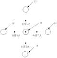
对于更多望远镜的数据融合处理可采用如图5所示的方法,图中假定各接收端望远镜11,12,…,1n的相位中心均关于发射端望远镜10的相位中心对称安装,则归算点1(发射端望远镜10与接收端望远镜11的中点)的测量数据和归算点3(发射端望远镜10与接收端望远镜13的中点)的测量数据又可形成基于发射端望远镜10相位中心的测量数据,同样归算点2(发射端望远镜10与接收端望远镜12的中点)与归算点4(发射端望远镜10与望接收端远镜14的中点)相对于发射端望远镜10对称,通过将各接收端望远镜11,12,…,1n两两对称地分布在发射端望远镜10周围,即可实现激光测量数据的融合归算处理,以将所有望远镜接收到的激光回波数据归算到发射端望远镜10,根据归算后的激光回波数据,即可准确获取空间目标4的距离。For the data fusion processing of more telescopes, the method shown in Figure 5 can be adopted. In the figure, it is assumed that the phase centers of the
8、实例8. Examples
上海天文台位于佘山观测基地的60cm口径发射端望远镜及1.56m口径接收端望远镜相距约60m,可用于并行接收大多数卫星的返回激光,是实施本发明的理想试验平台。60cm发射端望远镜向空间目标发射激光,同时与1.56m接收端望远镜并行接收返回的激光回波信号,然后将两个望远镜的测量数据进行融合处理,以验证多望远镜测量系统实现空间目标激光测距的测量效果。The distance between the 60cm-diameter transmitter telescope and the 1.56m-diameter receiver telescope at the Shanghai Astronomical Observatory at the Sheshan Observation Base is about 60m, which can be used to receive the return laser light of most satellites in parallel, and is an ideal test platform for implementing the present invention. The 60cm transmitter telescope emits laser light to the space target, and at the same time receives the returned laser echo signal in parallel with the 1.56m receiver telescope, and then fuses the measurement data of the two telescopes to verify that the multi-telescope measurement system realizes the space target laser ranging measurement effect.
图6A为仅使用60cm发射端望远镜对Ajisai卫星的激光测量的距离残差图,图6B为同时使用60cm发射端望远镜及1.56m接收端望远镜对Ajisai卫星的激光测量的距离残差图,测量精度(即RMS)分别为2.84cm和2.92cm。可见,两种情况的测量精度相当,验证了本发明中数据归算处理方法的合理可行性。对于更多望远镜的测量系统,只要多次应用此方法即可实现多个望远镜数据的融合处理。Figure 6A is the distance residual map of the laser measurement of the Ajisai satellite using only the 60cm transmitter telescope, and Figure 6B is the distance residual diagram of the laser measurement of the Ajisai satellite using the 60cm transmitter telescope and the 1.56m receiver telescope at the same time, and the measurement accuracy (ie RMS) are 2.84cm and 2.92cm respectively. It can be seen that the measurement accuracy of the two cases is equivalent, which verifies the rationality and feasibility of the data reduction processing method in the present invention. For a measurement system with more telescopes, as long as this method is applied multiple times, the fusion processing of multiple telescope data can be realized.
图6C为同时段内单台望远镜与双望远镜所接收到的激光回波数统计对比图(统计时段长为5秒)。从激光回波数统计可以看出,相对于单台60cm望远镜,双望远镜接收到的激光回波数提高了近一倍。如果采用更多望远镜接收激光回波信号,则可进一步有效增加总的回波数据量,实现单台大口径望远镜的等效接收效果。Figure 6C is a statistical comparison of the number of laser echoes received by a single telescope and a pair of telescopes in the same period (the statistical period is 5 seconds). From the statistics of the number of laser echoes, it can be seen that compared with a single 60cm telescope, the number of laser echoes received by the double telescope has nearly doubled. If more telescopes are used to receive laser echo signals, the total amount of echo data can be further effectively increased, and the equivalent receiving effect of a single large-aperture telescope can be achieved.
本发明采用的单发射系统向空间目标发射激光,应用多台不同位置分布的望远镜,对同一颗目标精确跟瞄、距离门控同步控制及数据融合处理等,实现多台望远镜对激光信号的同时接收,增加单位时间内激光回波数,实现单台大口径望远镜对空间目标的等效激光测量能力。该方法突破了单台望远镜接收口径限制,提升了对空间目标激光测量能力,在微弱激光回波信号的远距离激光测距、漫反射激光测距等领域中将具有良好应用效果。同时,多望远镜系统具有鲁棒性好、系统灵活、扩展性强等优点,可根据不同目标探测任务(能力),适时调整望远镜的数量。应用该方法,对于相距数百公里的多望远镜,还可实现空间目标的几何交会定位。The single emission system adopted in the present invention emits laser light to the space target, and uses multiple telescopes distributed in different positions to accurately track and aim at the same target, range gating synchronous control and data fusion processing, etc., so as to realize simultaneous detection of laser signals by multiple telescopes Receive, increase the number of laser echoes per unit time, and realize the equivalent laser measurement capability of a single large-aperture telescope for space targets. This method breaks through the limitation of the receiving aperture of a single telescope, improves the laser measurement capability of space targets, and will have good application effects in the fields of long-distance laser ranging and diffuse reflection laser ranging of weak laser echo signals. At the same time, the multi-telescope system has the advantages of good robustness, system flexibility, and strong scalability. The number of telescopes can be adjusted in due course according to different target detection tasks (capabilities). By applying this method, the geometric intersection positioning of space objects can also be realized for multiple telescopes separated by hundreds of kilometers.
以上所述的,仅为本发明的较佳实施例,并非用以限定本发明的范围,本发明的上述实施例还可以做出各种变化。即凡是依据本发明申请的权利要求书及说明书内容所作的简单、等效变化与修饰,皆落入本发明专利的权利要求保护范围。本发明未详尽描述的均为常规技术内容。What is described above is only a preferred embodiment of the present invention, and is not intended to limit the scope of the present invention. Various changes can also be made to the above embodiments of the present invention. That is to say, all simple and equivalent changes and modifications made according to the claims and description of the application for the present invention fall within the protection scope of the claims of the patent of the present invention. What is not described in detail in the present invention is conventional technical content.
Claims (8)
Priority Applications (1)
| Application Number | Priority Date | Filing Date | Title |
|---|---|---|---|
| CN201310548642.0ACN103529454A (en) | 2013-11-06 | 2013-11-06 | Multi-telescope laser ranging system and method |
Applications Claiming Priority (1)
| Application Number | Priority Date | Filing Date | Title |
|---|---|---|---|
| CN201310548642.0ACN103529454A (en) | 2013-11-06 | 2013-11-06 | Multi-telescope laser ranging system and method |
Publications (1)
| Publication Number | Publication Date |
|---|---|
| CN103529454Atrue CN103529454A (en) | 2014-01-22 |
Family
ID=49931607
Family Applications (1)
| Application Number | Title | Priority Date | Filing Date |
|---|---|---|---|
| CN201310548642.0APendingCN103529454A (en) | 2013-11-06 | 2013-11-06 | Multi-telescope laser ranging system and method |
Country Status (1)
| Country | Link |
|---|---|
| CN (1) | CN103529454A (en) |
Cited By (11)
| Publication number | Priority date | Publication date | Assignee | Title |
|---|---|---|---|---|
| CN104251994A (en)* | 2014-09-11 | 2014-12-31 | 上海卫星工程研究所 | Control-point-free satellite precise positioning system and method realized through long-baseline laser ranging |
| CN105486305A (en)* | 2014-09-17 | 2016-04-13 | 上海新跃仪表厂 | Short-range relative navigation filtering method for evaluating accelerometer drift |
| CN105954727A (en)* | 2016-04-25 | 2016-09-21 | 中国科学院上海天文台 | Range-gate control pulse signal generating system |
| CN107015234A (en)* | 2017-05-19 | 2017-08-04 | 中国科学院国家天文台长春人造卫星观测站 | Embedded satellite laser ranging control system |
| CN109270494A (en)* | 2018-09-21 | 2019-01-25 | 电子科技大学 | A kind of High Accuracy Radar measuring system anti-interference method |
| CN110520757A (en)* | 2017-01-05 | 2019-11-29 | 图达通爱尔兰有限公司 | High-Resolution LiDAR Using High-Frequency Pulse Shooting |
| CN113009455A (en)* | 2021-04-14 | 2021-06-22 | 吉林大学 | Method and system for improving pulse laser ranging precision |
| CN113447999A (en)* | 2021-07-08 | 2021-09-28 | 天津大学 | Atmospheric parameter measuring method and device based on laser data |
| CN116018537A (en)* | 2020-07-08 | 2023-04-25 | 罗纳德·F·丹托维茨 | Telescope array system and processing method |
| CN117348016A (en)* | 2023-10-10 | 2024-01-05 | 中国科学院云南天文台 | One-shot-and-multiple-shot laser ranging method for low-orbit space debris |
| CN117826170A (en)* | 2024-01-05 | 2024-04-05 | 中国科学院国家天文台长春人造卫星观测站 | Receiving-transmitting separated moon laser ranging method, system, storage medium and equipment |
Citations (9)
| Publication number | Priority date | Publication date | Assignee | Title |
|---|---|---|---|---|
| CN1511265A (en)* | 2001-03-29 | 2004-07-07 | Ses阿斯特拉有限公司 | Ranging system for determining ranging information of spacecraft |
| CN101236253A (en)* | 2008-03-07 | 2008-08-06 | 中国科学院上海光学精密机械研究所 | High-precision speed measuring and ranging laser radar system and speed measuring and ranging method |
| JP2009115696A (en)* | 2007-11-08 | 2009-05-28 | Mitsubishi Electric Corp | Lightwave radar device |
| EP2405287A1 (en)* | 2010-07-08 | 2012-01-11 | Centre National D'etudes Spatiales | Device for remote laser detection and interferometry method |
| CN102393523A (en)* | 2011-08-04 | 2012-03-28 | 长春理工大学 | Method for measuring distance by using picosecond pulse-based high-accuracy laser distance measuring device |
| CN102645654A (en)* | 2011-02-16 | 2012-08-22 | 和硕联合科技股份有限公司 | Distance detection device and method |
| CN102680980A (en)* | 2012-04-26 | 2012-09-19 | 北京航空航天大学 | Pulse laser distance measuring method |
| CN102854510A (en)* | 2012-08-16 | 2013-01-02 | 苏州启智机电技术有限公司 | High precision laser range finder |
| CN103368655A (en)* | 2013-06-21 | 2013-10-23 | 哈尔滨工业大学深圳研究生院 | Telescope array optical signal reception method and telescope array optical signal reception device based on self-adaptation control |
- 2013
- 2013-11-06CNCN201310548642.0Apatent/CN103529454A/enactivePending
Patent Citations (9)
| Publication number | Priority date | Publication date | Assignee | Title |
|---|---|---|---|---|
| CN1511265A (en)* | 2001-03-29 | 2004-07-07 | Ses阿斯特拉有限公司 | Ranging system for determining ranging information of spacecraft |
| JP2009115696A (en)* | 2007-11-08 | 2009-05-28 | Mitsubishi Electric Corp | Lightwave radar device |
| CN101236253A (en)* | 2008-03-07 | 2008-08-06 | 中国科学院上海光学精密机械研究所 | High-precision speed measuring and ranging laser radar system and speed measuring and ranging method |
| EP2405287A1 (en)* | 2010-07-08 | 2012-01-11 | Centre National D'etudes Spatiales | Device for remote laser detection and interferometry method |
| CN102645654A (en)* | 2011-02-16 | 2012-08-22 | 和硕联合科技股份有限公司 | Distance detection device and method |
| CN102393523A (en)* | 2011-08-04 | 2012-03-28 | 长春理工大学 | Method for measuring distance by using picosecond pulse-based high-accuracy laser distance measuring device |
| CN102680980A (en)* | 2012-04-26 | 2012-09-19 | 北京航空航天大学 | Pulse laser distance measuring method |
| CN102854510A (en)* | 2012-08-16 | 2013-01-02 | 苏州启智机电技术有限公司 | High precision laser range finder |
| CN103368655A (en)* | 2013-06-21 | 2013-10-23 | 哈尔滨工业大学深圳研究生院 | Telescope array optical signal reception method and telescope array optical signal reception device based on self-adaptation control |
Non-Patent Citations (2)
| Title |
|---|
| V. VILNROTTER等: "An Optical Array Receiver for Deep-Space Communication through Atmospheric Turbulence", 《JOURNAL OF LIGHT WAVE TECHNOLOGY》, 15 August 2003 (2003-08-15), pages 1 - 21* |
| 吴志波等: "基于FPGA的高重复率距离门控电路实现", 《电子学报》, vol. 38, no. 4, 30 April 2010 (2010-04-30), pages 919 - 922* |
Cited By (16)
| Publication number | Priority date | Publication date | Assignee | Title |
|---|---|---|---|---|
| CN104251994A (en)* | 2014-09-11 | 2014-12-31 | 上海卫星工程研究所 | Control-point-free satellite precise positioning system and method realized through long-baseline laser ranging |
| CN105486305A (en)* | 2014-09-17 | 2016-04-13 | 上海新跃仪表厂 | Short-range relative navigation filtering method for evaluating accelerometer drift |
| CN105486305B (en)* | 2014-09-17 | 2018-12-28 | 上海新跃仪表厂 | A kind of short range Relative Navigation filtering method of estimated acceleration meter drift |
| CN105954727A (en)* | 2016-04-25 | 2016-09-21 | 中国科学院上海天文台 | Range-gate control pulse signal generating system |
| CN110520757A (en)* | 2017-01-05 | 2019-11-29 | 图达通爱尔兰有限公司 | High-Resolution LiDAR Using High-Frequency Pulse Shooting |
| CN110520757B (en)* | 2017-01-05 | 2023-11-03 | 图达通智能美国有限公司 | High-resolution LiDAR using high-frequency pulse shots |
| CN107015234A (en)* | 2017-05-19 | 2017-08-04 | 中国科学院国家天文台长春人造卫星观测站 | Embedded satellite laser ranging control system |
| CN107015234B (en)* | 2017-05-19 | 2019-08-09 | 中国科学院国家天文台长春人造卫星观测站 | Embedded satellite laser ranging control system |
| CN109270494A (en)* | 2018-09-21 | 2019-01-25 | 电子科技大学 | A kind of High Accuracy Radar measuring system anti-interference method |
| CN116018537A (en)* | 2020-07-08 | 2023-04-25 | 罗纳德·F·丹托维茨 | Telescope array system and processing method |
| CN113009455B (en)* | 2021-04-14 | 2022-06-03 | 吉林大学 | A method and system for improving the accuracy of pulsed laser ranging |
| CN113009455A (en)* | 2021-04-14 | 2021-06-22 | 吉林大学 | Method and system for improving pulse laser ranging precision |
| CN113447999B (en)* | 2021-07-08 | 2022-05-13 | 天津大学 | A method and equipment for measuring atmospheric parameters based on laser data |
| CN113447999A (en)* | 2021-07-08 | 2021-09-28 | 天津大学 | Atmospheric parameter measuring method and device based on laser data |
| CN117348016A (en)* | 2023-10-10 | 2024-01-05 | 中国科学院云南天文台 | One-shot-and-multiple-shot laser ranging method for low-orbit space debris |
| CN117826170A (en)* | 2024-01-05 | 2024-04-05 | 中国科学院国家天文台长春人造卫星观测站 | Receiving-transmitting separated moon laser ranging method, system, storage medium and equipment |
Similar Documents
| Publication | Publication Date | Title |
|---|---|---|
| CN103529454A (en) | Multi-telescope laser ranging system and method | |
| CN103941263B (en) | A kind of H_2O maser method based on quantum light source on star and catoptron | |
| CN101793526B (en) | Autonomous relative navigation method for multi-information fusion formation spacecrafts | |
| CN103345145B (en) | A kind of method utilizing laser to carry out spaceborne clock measurement | |
| Benson | Enhancing space situational awareness using passive radar from space based emitters of opportunity | |
| US9140556B1 (en) | Method and system for gamma-ray localization induced spacecraft navigation using celestial gamma-ray sources | |
| CN102866407A (en) | Satellite navigation anti-interference test simulator and simulation method thereof | |
| AU2012245010B2 (en) | Process and system to determine temporal changes in retransmission and propagation of signals used to measure distances, syncronize actuators and georeference applications | |
| JP2020193972A (en) | Method and apparatus for positioning with wireless signals | |
| CN109991837B (en) | A system and method for comparing clocks in two places using laser common view | |
| CN108254760B (en) | A positioning and navigation method and system based on three quantum satellites | |
| CN104535992A (en) | Artificial satellite laser ranging system | |
| CN110986962B (en) | A full-arc orbit determination method for low-orbit satellites based on high-orbit communication satellites | |
| CN104133221A (en) | Pseudolite positioning system based on universal receiver | |
| Zhang et al. | Applications of satellite laser ranging and laser time transfer in BeiDou navigation satellite system | |
| RU2319173C1 (en) | Multi-functional radiolocation station for aircrafts | |
| CN102226844A (en) | Inter-satellite ranging method for formation small satellites based on two-way forwarding measurement system and carrier phase smoothing pseudocode | |
| RU2526401C1 (en) | Method for radar doppler angular measurements of spacecraft and system for realising said method | |
| RU2543078C1 (en) | Jamming method and device | |
| RU2525343C1 (en) | Method for simultaneous determination of six motion parameters of spacecraft when making trajectory measurements and system for realising said method | |
| CN113534225A (en) | Method for positioning target at indoor and outdoor joint of Beidou and ultra wide band based on multipath utilization | |
| CN102721956B (en) | Echo signal acquisition and transmission method in light beam aiming system | |
| CN105353385B (en) | ARAIM nominal offsets evaluation method and device based on the frequency of the Big Dipper three | |
| Zhao et al. | Uwb-rtk positioning system based on tdoa | |
| JP2020043562A (en) | Ground time virtual reference based positioning and timing system |
Legal Events
| Date | Code | Title | Description |
|---|---|---|---|
| C06 | Publication | ||
| PB01 | Publication | ||
| C10 | Entry into substantive examination | ||
| SE01 | Entry into force of request for substantive examination | ||
| C02 | Deemed withdrawal of patent application after publication (patent law 2001) | ||
| WD01 | Invention patent application deemed withdrawn after publication | Application publication date:20140122 |