CN103529313A - Test machine and method for driving device of backlight module and manufacturing method of power supply board - Google Patents
Test machine and method for driving device of backlight module and manufacturing method of power supply boardDownload PDFInfo
- Publication number
- CN103529313A CN103529313ACN201210230046.3ACN201210230046ACN103529313ACN 103529313 ACN103529313 ACN 103529313ACN 201210230046 ACN201210230046 ACN 201210230046ACN 103529313 ACN103529313 ACN 103529313A
- Authority
- CN
- China
- Prior art keywords
- backlight module
- driving device
- emitting diode
- power supply
- light
- Prior art date
- Legal status (The legal status is an assumption and is not a legal conclusion. Google has not performed a legal analysis and makes no representation as to the accuracy of the status listed.)
- Granted
Links
- 238000012360testing methodMethods0.000titleclaimsabstractdescription59
- 238000004519manufacturing processMethods0.000titleclaimsabstractdescription12
- 238000000034methodMethods0.000titleabstractdescription15
- 239000000523sampleSubstances0.000claimsabstractdescription12
- 230000008859changeEffects0.000claimsabstractdescription8
- 229910000679solderInorganic materials0.000claimsdescription5
- 238000010998test methodMethods0.000claimsdescription4
- 230000008878couplingEffects0.000claimsdescription2
- 238000010168coupling processMethods0.000claimsdescription2
- 238000005859coupling reactionMethods0.000claimsdescription2
- 238000012856packingMethods0.000claimsdescription2
- 238000005286illuminationMethods0.000claims3
- 230000001795light effectEffects0.000claims3
- 238000003466weldingMethods0.000abstract1
- 238000005516engineering processMethods0.000description7
- 238000013461designMethods0.000description3
- 238000004806packaging method and processMethods0.000description3
- 238000005476solderingMethods0.000description2
- ATJFFYVFTNAWJD-UHFFFAOYSA-NTinChemical compound[Sn]ATJFFYVFTNAWJD-UHFFFAOYSA-N0.000description1
- 238000003780insertionMethods0.000description1
- 230000037431insertionEffects0.000description1
- 238000007689inspectionMethods0.000description1
- 239000004973liquid crystal related substanceSubstances0.000description1
- 239000000463materialSubstances0.000description1
- 238000012986modificationMethods0.000description1
- 230000004048modificationEffects0.000description1
- 230000008569processEffects0.000description1
- 230000008439repair processEffects0.000description1
Images


Classifications
- G—PHYSICS
- G01—MEASURING; TESTING
- G01R—MEASURING ELECTRIC VARIABLES; MEASURING MAGNETIC VARIABLES
- G01R31/00—Arrangements for testing electric properties; Arrangements for locating electric faults; Arrangements for electrical testing characterised by what is being tested not provided for elsewhere
- G01R31/44—Testing lamps
- G—PHYSICS
- G01—MEASURING; TESTING
- G01R—MEASURING ELECTRIC VARIABLES; MEASURING MAGNETIC VARIABLES
- G01R31/00—Arrangements for testing electric properties; Arrangements for locating electric faults; Arrangements for electrical testing characterised by what is being tested not provided for elsewhere
- G01R31/28—Testing of electronic circuits, e.g. by signal tracer
- G01R31/2801—Testing of printed circuits, backplanes, motherboards, hybrid circuits or carriers for multichip packages [MCP]
- G01R31/2806—Apparatus therefor, e.g. test stations, drivers, analysers, conveyors
- G—PHYSICS
- G01—MEASURING; TESTING
- G01F—MEASURING VOLUME, VOLUME FLOW, MASS FLOW OR LIQUID LEVEL; METERING BY VOLUME
- G01F3/00—Measuring the volume flow of fluids or fluent solid material wherein the fluid passes through the meter in successive and more or less isolated quantities, the meter being driven by the flow
- G—PHYSICS
- G01—MEASURING; TESTING
- G01R—MEASURING ELECTRIC VARIABLES; MEASURING MAGNETIC VARIABLES
- G01R3/00—Apparatus or processes specially adapted for the manufacture or maintenance of measuring instruments, e.g. of probe tips
- G—PHYSICS
- G01—MEASURING; TESTING
- G01R—MEASURING ELECTRIC VARIABLES; MEASURING MAGNETIC VARIABLES
- G01R31/00—Arrangements for testing electric properties; Arrangements for locating electric faults; Arrangements for electrical testing characterised by what is being tested not provided for elsewhere
- G01R31/28—Testing of electronic circuits, e.g. by signal tracer
- G01R31/316—Testing of analog circuits
- G01R31/3161—Marginal testing
- Y—GENERAL TAGGING OF NEW TECHNOLOGICAL DEVELOPMENTS; GENERAL TAGGING OF CROSS-SECTIONAL TECHNOLOGIES SPANNING OVER SEVERAL SECTIONS OF THE IPC; TECHNICAL SUBJECTS COVERED BY FORMER USPC CROSS-REFERENCE ART COLLECTIONS [XRACs] AND DIGESTS
- Y10—TECHNICAL SUBJECTS COVERED BY FORMER USPC
- Y10T—TECHNICAL SUBJECTS COVERED BY FORMER US CLASSIFICATION
- Y10T29/00—Metal working
- Y10T29/49—Method of mechanical manufacture
- Y10T29/49002—Electrical device making
- Y10T29/49004—Electrical device making including measuring or testing of device or component part
Landscapes
- Physics & Mathematics (AREA)
- General Physics & Mathematics (AREA)
- Engineering & Computer Science (AREA)
- General Engineering & Computer Science (AREA)
- Computer Hardware Design (AREA)
- Microelectronics & Electronic Packaging (AREA)
- Fluid Mechanics (AREA)
- Liquid Crystal (AREA)
- Circuit Arrangement For Electric Light Sources In General (AREA)
Abstract
Description
Translated fromChinese技术领域technical field
本发明涉及显示器电源板(monitor power board)上的一发光二极管背光模块驱动装置(LED backlightmodule driver)的测试机台与方法及电源板制作方法。The invention relates to a test machine and method for an LED backlight module driver (LED backlight module driver) on a monitor power board and a method for manufacturing the power board.
背景技术Background technique
现今显示器(如,液晶显示器)通常需要一背光模块提供背光。发光二极管常用来实现背光源,可制作成一发光二极管背光模块。显示器电源板上通常设计有一发光二极管背光模块驱动装置,用于驱动该发光二极管背光模块。Today's displays (eg, liquid crystal displays) usually require a backlight module to provide backlight. Light-emitting diodes are commonly used to implement backlight sources, and can be fabricated into a light-emitting diode backlight module. A light emitting diode backlight module driving device is usually designed on the display power board for driving the light emitting diode backlight module.
在成本考虑下,实际组装显示器前需对其中的组件(例如,显示器电源板)进行测试,确保各组件可正常工作,避免之后拆装成品的损害风险(例如,显示器外壳拆卸时极容易损坏)。当然,显示器电源板上的发光二极管背光模块驱动器也需要进行测试。市面上专业仪器厂商所推行的发光二极管负载机即是为了测试发光二极管背光模块驱动装置而设计,但仪器费用相当昂贵。In consideration of cost, the components (for example, the display power board) need to be tested before the actual assembly of the display to ensure that each component can work normally and avoid the risk of damage to the finished product after disassembly (for example, the display case is easily damaged when disassembled) . Of course, the LED backlight module driver on the display power board also needs to be tested. The LED load machine implemented by professional instrument manufacturers in the market is designed to test the LED backlight module driving device, but the cost of the equipment is quite expensive.
因此,需要提供一种背光模块驱动装置测试机台与方法及电源板制作方法来解决上述问题。Therefore, it is necessary to provide a test machine and method for a backlight module driving device and a method for manufacturing a power board to solve the above problems.
发明内容Contents of the invention
本发明公开一种发光二极管背光模块驱动装置测试机台与测试方法以及显示器电源板制作方法。The invention discloses a test machine and a test method for a light-emitting diode backlight module driving device and a method for manufacturing a display power board.
根据所公开的技术实现的一种发光二极管背光模块驱动装置测试机台包括:一测试夹具以及一开关切换式发光二极管光管负载;该测试夹具提供测试探针接触一显示器电源板上的焊点;该开关切换式发光二极管光管负载耦接该测试夹具,并且经由该测试夹具的测试探针耦接该显示器电源板的一发光二极管背光模块驱动装置;其中,该开关切换式发光二极管光管负载包括:多条光管以及多个切换开关;各该光管包括串接的多个发光二极管;各该切换开关与一条上述光管的局部的发光二极管并联,以改变该条光管的有效发光二极管数量,其中,该等切换开关的状态与该显示器电源板所适用的一显示器的规格相关。A light-emitting diode backlight module driving device testing machine realized according to the disclosed technology includes: a test fixture and a switchable light-emitting diode light pipe load; the test fixture provides test probes to contact solder joints on a display power supply board The switchable LED light pipe load is coupled to the test fixture, and is coupled to an LED backlight module driving device of the display power board via the test probe of the test fixture; wherein, the switchable LED light pipe The load includes: a plurality of light pipes and a plurality of switching switches; each of the light pipes includes a plurality of light-emitting diodes connected in series; each of the switching switches is connected in parallel with a local light-emitting diode of one of the above-mentioned light pipes to change the effective The number of light-emitting diodes, wherein the states of the switches are related to the specifications of a display that the display power board is suitable for.
根据所公开的技术实现的一种发光二极管背光模块驱动装置测试方法包括:提供一开关切换式发光二极管光管负载耦接一显示器电源板的一发光二极管背光模块驱动装置,其中,该开关切换式发光二极管光管负载包括:多条光管以及多个切换开关;各该光管包括串接的多个发光二极管;各该切换开关与一条上述光管的局部的发光二极管并联,以改变该条光管的有效发光二极管数量;根据该显示器电源板所适用的一显示器的规格设定该开关切换式发光二极管光管负载的该等切换开关;提供一交流电源给该显示器电源板的一开关电源,该开关电源耦接该发光二极管背光模块驱动装置;提供一背光启动/关闭控制信号以及一背光亮度控制信号给该发光二极管背光模块驱动装置;收集该发光二极管背光模块驱动装置供应给该开关切换式发光二极管光管负载的一驱动电压;以及根据该驱动电压判断该发光二极管背光模块驱动装置是否正常运作。A LED backlight module driving device testing method realized according to the disclosed technology includes: providing a LED backlight module driving device with a switchable LED light pipe load coupled to a display power board, wherein the switchable The light-emitting diode light pipe load includes: a plurality of light pipes and a plurality of switches; each of the light pipes includes a plurality of light-emitting diodes connected in series; The number of effective light-emitting diodes of the light pipe; setting the switching switches of the switching light-emitting diode light pipe load according to the specification of a display suitable for the display power board; providing an AC power supply to a switching power supply of the display power board , the switching power supply is coupled to the LED backlight module driving device; providing a backlight start/stop control signal and a backlight brightness control signal to the LED backlight module driving device; collecting the LED backlight module driving device to supply to the switch switch a driving voltage of the light emitting diode light tube load; and judging whether the driving device of the light emitting diode backlight module is in normal operation according to the driving voltage.
根据所公开的技术实现的一种显示器电源板制作方法包括:在产品包装前,将一开关切换式发光二极管光管负载耦接所制作的显示器电源板的一发光二极管背光模块驱动装置,其中,该开关切换式发光二极管光管负载包括:多条光管以及多个切换开关;各该光管包括串接的多个发光二极管;各该切换开关与一条上述光管的局部的发光二极管并联,以改变该条光管的有效发光二极管数量;根据该显示器电源板所适用的一显示器的规格设定该开关切换式发光二极管光管负载的该等切换开关;提供一交流电源给该显示器电源板的一开关电源,该开关电源耦接该发光二极管背光模块驱动装置;提供一背光启动/关闭控制信号以及一背光亮度控制信号给该发光二极管背光模块驱动装置;收集该发光二极管背光模块驱动装置供应给该开关切换式发光二极管光管负载的一驱动电压;根据该驱动电压判断该发光二极管背光模块驱动装置是否正常运作;以及在确认该发光二极管背光模块驱动装置为正常后包装该显示器电源板。A method for manufacturing a display power board realized according to the disclosed technology includes: before packaging the product, coupling a switchable light-emitting diode light pipe load to an LED backlight module driving device of the manufactured display power board, wherein, The switch-switchable light-emitting diode light pipe load includes: a plurality of light pipes and a plurality of switches; each light pipe includes a plurality of light-emitting diodes connected in series; each change-over switch is connected in parallel with a partial light-emitting diode of the light pipe, To change the number of effective light-emitting diodes of the light pipe; set the switching switches of the switchable light-emitting diode light pipe load according to the specifications of a display that the display power board is suitable for; provide an AC power supply to the display power board A switching power supply, the switching power supply is coupled to the LED backlight module driving device; providing a backlight start/stop control signal and a backlight brightness control signal to the LED backlight module driving device; collecting the light emitting diode backlight module driving device supply A drive voltage for the switchable LED light tube load; judging whether the LED backlight module driving device is in normal operation according to the driving voltage; and packing the display power board after confirming that the LED backlight module driving device is normal.
本发明不仅切换方便且成本低廉。The invention is not only convenient to switch but also low in cost.
为使本发明的上述目的、特征和优点能更明显易懂,下文特举实施例,并配合所附附图,详细说明如下。In order to make the above-mentioned objects, features and advantages of the present invention more comprehensible, the following specific embodiments are described in detail in conjunction with the accompanying drawings.
附图说明Description of drawings
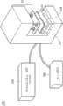
图1A图解根据本发明的技术所实现的一发光二极管背光模块驱动装置测试机台100;FIG. 1A illustrates a light emitting diode backlight module driving
图1B详细绘制该显示器电源板PB内部功能模块与上述电子负载机106以及开关切换式发光二极管光管负载108的连结关系;FIG. 1B draws in detail the connection relationship between the internal functional modules of the display power board PB, the above-mentioned
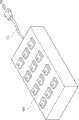
图2图解所公开的开关切换式发光二极管光管负载的一种实施方式;FIG. 2 illustrates an embodiment of the disclosed switchable light-emitting diode light pipe load;
图3以流程图图解一种发光二极管背光模块驱动装置测试方法;FIG. 3 illustrates a method for testing a LED backlight module driving device with a flow chart;
图4图解开关切换式发光二极管光管负载200的一种外壳设计;FIG. 4 illustrates a housing design of a switchable LED
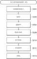
图5以流程图图解一显示器电源板制作方法。FIG. 5 illustrates a method of manufacturing a display power board with a flow chart.
主要组件符号说明:Description of main component symbols:
100 发光二极管背光模块驱动装置测试机台100 LED backlight module driving device testing machine
102 测试夹具102 Test fixture
104 测试探针104 Test probe
106 电子负载机106 Electronic Loader
108 开关切换式发光二极管光管负载108 Switchable light-emitting diode light tube load
110 测试压床110 Test press
122 开关电源122 Switching power supply
124 升压电路124 Boost circuit
126 发光二极管背光模块驱动装置126 LED backlight module driving device
128 交流电源128 AC power supply
130 背光启动/关闭控制信号130 Backlight on/off control signal
132 背光亮度控制信号132 Backlight brightness control signal
134 直流电源输出端134 DC power output terminal
200 开关切换式发光二极管光管负载200 Switchable light-emitting diode light tube load
400 开关切换式发光二极管光管负载的外壳400 Switchable light-emitting diode light tube load shell
CL 缆线CL Cable
I_sense1~4 感测电流I_sense1~4 sense current
PB 显示器电源板PB Display Power Board
S11…S14、S21…S24、S31…S34 切换开关S11…S14, S21…S24, S31…S34 switch
S302…S310 步骤S302…S310 Steps
S502…S514 步骤S502…S514 Steps
V_LED 驱动电压V_LED Driving Voltage
具体实施方式Detailed ways
图1A图解根据本发明的技术所实现的一发光二极管背光模块驱动装置测试机台100,用以测试一显示器电源板PB。机台100包括:一测试夹具(也称治具)102(提供有测试探针104)、一电子负载机106、一开关切换式发光二极管光管负载108以及一测试压床110。FIG. 1A illustrates an LED backlight module driving
如图所示,测试夹具102设计有置放该显示器电源板PB的空间,用以使该显示器电源板PB上的焊点得以与该测试夹具102所提供的测试探针104接触。测试压床110为选用设备,用来下压该显示器电源板PB,使该测试夹具102的测试探针104得以与显示器电源板PB上的焊点更为贴合。As shown in the figure, the
此外,测试夹具102可以缆线(如图所示)与该电子负载机106以及该开关切换式发光二极管光管负载108耦接。该电子负载机106以及该开关切换式发光二极管光管负载108经由该测试夹具102的测试探针104与该显示器电源板PB内的功能模块耦接。图1B还详细绘制该显示器电源板PB内部功能模块与上述电子负载机106以及开关切换式发光二极管光管负载108的连结关系。In addition, the
参阅图1B,首先介绍显示器电源板PB内部功能模块。该显示器电源板PB可包括一开关电源122、一升压电路124以及一发光二极管背光模块驱动装置126。外接的交流电源128经该开关电源122以及该升压电路124处理后供应给该发光二极管背光模块驱动装置126。供有电力的该发光二极管背光模块驱动装置126根据一背光启动/关闭控制信号130以及一背光亮度控制信号132动作。此外,开关电源122还负责直流电源的供应,以该显示器电源板PB的一直流电源输出端134输出。Referring to FIG. 1B , the internal functional modules of the display power board PB are firstly introduced. The display power board PB can include a
为了测试该显示器电源板PB,该电子负载机106耦接该直流电源输出端134模拟直流负载,且该开关切换式发光二极管光管负载108模拟一背光模块作为该发光二极管背光模块驱动装置126的负载。以下主要讨论该发光二极管背光模块驱动装置126的测试。如图所示,在供应有交流电源128、背光启动/关闭控制信号130以及背光亮度控制信号132的状态下,该发光二极管背光模块驱动装置126供应给该开关切换式发光二极管光管负载108一驱动电压V_LED,且感测电流I_sense1~4可回传给该发光二极管背光模块驱动装置126作为启动电路保护的依据。驱动电压V_LED是否以预期值操作即显示该发光二极管背光模块驱动装置126是否正常运作。In order to test the display power board PB, the
本发明对该开关切换式发光二极管光管负载108有特殊的结构设计,图2图解一种实施方式。一开关切换式发光二极管光管负载200包括4条光管以及12个切换开关S11~S14、S21~S24、S31~S34。The present invention has a special structural design for the switchable light-emitting diode
图2所示的各光管包括串接的10个发光二极管。该等发光二极管可以特殊材质实现;例如,相比一般背光模块实际使用的发光二极管,负载200所示的发光二极管具有较高的顺向电流(IF)参数,得以承受较高的工作电流。Each light pipe shown in FIG. 2 includes 10 LEDs connected in series. These light emitting diodes can be realized with special materials; for example, compared with the light emitting diodes actually used in common backlight modules, the light emitting diodes shown by the
图2所示的各切换开关与一条光管的局部的发光二极管并联,以改变该条光管的有效发光二极管数量;而该等切换开关S11~S14、S21~S24、S31~S34的状态与显示器电源板PB用的一显示器的规格相关。以下表格举例说明该等切换开关S11~S14、S21~S24、S31~S34的设定方式:Each switching switch shown in Figure 2 is connected in parallel with a local light emitting diode of a light pipe to change the effective number of light emitting diodes of the light pipe; The specifications of a display used by the display power board PB are related. The following table illustrates the setting methods of these switches S11~S14, S21~S24, S31~S34:

如此一来,该开关切换式发光二极管光管负载200可模拟至少三种规格的显示器的背光模块,不仅切换方便且成本低廉。In this way, the switchable LED
特别声明的是,图2所示的光管数量与各光管串接的发光二极管数量以及切换开关数量并不意图限定本发明的范围,使用者可能视需求变动之。In particular, the number of light pipes, the number of LEDs connected in series to each light pipe, and the number of switches shown in FIG. 2 are not intended to limit the scope of the present invention, and users may change them according to requirements.
利用以上所公开的开关切换式发光二极管光管负载108/200,图3以流程图图解一种发光二极管背光模块驱动装置测试方法。步骤S302提供上述开关切换式发光二极管光管负载108/200耦接一显示器电源板(PB)的一发光二极管背光模块驱动装置(126)。步骤S304根据该显示器电源板(PB)所适用的一显示器的规格设定该开关切换式发光二极管光管负载108/200该等切换开关(如以上表格对切换开关的设定)。步骤S306提供一交流电源(128)给该显示器电源板(PB)中耦接该发光二极管背光模块驱动装置(126)的一开关电源(122)。并且,步骤S306提供一背光启动/关闭控制信号(130)以及一背光亮度控制信号(132)给该发光二极管背光模块驱动装置(126)。步骤S308收集该发光二极管背光模块驱动装置(126)供应给该开关切换式发光二极管光管负载108/200的一驱动电压(V_LED)。步骤S310根据该驱动电压(V_LED)判断该发光二极管背光模块驱动装置(126)是否正常运作。一种实施方式是根据该驱动电压(V_LED)是否以预期值操作来判断该发光二极管背光模块驱动装置(126)是否正常运作。Using the switchable LED
关于所公开的开关切换式发光二极管光管负载108/200,一种实施方式允许使用者以手动方式设定其中切换开关。以图2所示负载200为例,图4图解其外壳400的设计。负载200的12个切换开关S11~S14、S21~S24、S31~S34由外壳400所提供的12个手动开关分开控制。缆线CL即用来与待测的显示器电源板PB连结。Regarding the disclosed switchable LED
在其他实施方式中,负载108/200内的该等切换开关也可以程序化方式设定。In other implementations, the switches in the
以上发光二极管背光模块驱动装置测试技术亦可应用于显示器电源板的制作程序中。图5以流程图图解一显示器电源板制作方法。步骤S502进行AI/SMT(自动插件/表面黏着)板投入。步骤S504进行插件。步骤S506进行波峰焊。步骤S508进行锡检/补焊。步骤S510进行ICT(in circuit test)程序。步骤S512进行FCT(function test)程序。步骤S514进行产品包装。所公开的发光二极管背光模块驱动装置测试技术(例如,图3所示的流程)即被设计在步骤S512中实行,早于步骤S514的产品包装。The above LED backlight module driving device testing technology can also be applied to the production process of the display power board. FIG. 5 illustrates a method of manufacturing a display power board with a flow chart. Step S502 is to carry out AI/SMT (automatic insertion/surface mount) board input. Step S504 performs plug-in. Step S506 performs wave soldering. Step S508 performs tin inspection/repair soldering. Step S510 carries out ICT (in circuit test) procedure. Step S512 carries out the FCT (function test) procedure. Step S514 carries out product packaging. The disclosed LED backlight module driving device testing technology (for example, the process shown in FIG. 3 ) is designed to be implemented in step S512 , earlier than the product packaging in step S514 .
虽然本发明已以较佳实施例公开如上,然而其并非用以限定本发明,任何本领域的技术人员,在不脱离本发明的精神和范围内,应当可做些许更动与润饰,因此本发明的保护范围应当视所附的权利要求书的范围所界定者为准。Although the present invention has been disclosed above with preferred embodiments, it is not intended to limit the present invention. Any person skilled in the art should be able to make some changes and modifications without departing from the spirit and scope of the present invention. Therefore, this The scope of protection of the invention should be defined by the scope of the appended claims.
Claims (9)
Priority Applications (3)
| Application Number | Priority Date | Filing Date | Title |
|---|---|---|---|
| CN201210230046.3ACN103529313B (en) | 2012-07-04 | 2012-07-04 | Test machine and method for driving device of backlight module and manufacturing method of power supply board |
| TW101125107ATWI486606B (en) | 2012-07-04 | 2012-07-12 | Test station and test method for light emitting diode backlight module driver, and, production method for monitor power board |
| US13/846,065US9151805B2 (en) | 2012-07-04 | 2013-03-18 | Test machine and the test method for light emitting diode backlight driver, and, manufacturing method for monitor power board |
Applications Claiming Priority (1)
| Application Number | Priority Date | Filing Date | Title |
|---|---|---|---|
| CN201210230046.3ACN103529313B (en) | 2012-07-04 | 2012-07-04 | Test machine and method for driving device of backlight module and manufacturing method of power supply board |
Publications (2)
| Publication Number | Publication Date |
|---|---|
| CN103529313Atrue CN103529313A (en) | 2014-01-22 |
| CN103529313B CN103529313B (en) | 2016-03-16 |
Family
ID=49878030
Family Applications (1)
| Application Number | Title | Priority Date | Filing Date |
|---|---|---|---|
| CN201210230046.3AExpired - Fee RelatedCN103529313B (en) | 2012-07-04 | 2012-07-04 | Test machine and method for driving device of backlight module and manufacturing method of power supply board |
Country Status (3)
| Country | Link |
|---|---|
| US (1) | US9151805B2 (en) |
| CN (1) | CN103529313B (en) |
| TW (1) | TWI486606B (en) |
Cited By (4)
| Publication number | Priority date | Publication date | Assignee | Title |
|---|---|---|---|---|
| CN104616611A (en)* | 2015-02-15 | 2015-05-13 | 合肥鑫晟光电科技有限公司 | Lighting detection equipment and lighting detection method |
| CN107367683A (en)* | 2017-07-05 | 2017-11-21 | 佛山杰致信息科技有限公司 | A kind of LED circuit board detection means |
| CN107942224A (en)* | 2017-11-03 | 2018-04-20 | 莱诺斯科技(北京)股份有限公司 | A kind of veneer automatical measure and control system and method |
| CN109917211A (en)* | 2019-03-29 | 2019-06-21 | 江苏核电有限公司 | A kind of direct current supply module Alarm Monitor Unit |
Families Citing this family (5)
| Publication number | Priority date | Publication date | Assignee | Title |
|---|---|---|---|---|
| CN102821523A (en)* | 2012-08-16 | 2012-12-12 | 浙江生辉照明有限公司 | LED (Light-Emitting Diode) lighting device and service life verification method thereof |
| CN104053281B (en)* | 2014-06-16 | 2016-12-21 | 京东方光科技有限公司 | Lighting jig |
| CN105044626A (en)* | 2015-08-25 | 2015-11-11 | 苏州欧可罗电子科技有限公司 | LED light bar aging method |
| CN109507614B (en)* | 2018-11-21 | 2021-03-23 | 江苏新广联光电股份有限公司 | Testing device for emergency lighting lamp |
| CN113533999B (en)* | 2021-07-29 | 2024-09-10 | 横店集团得邦照明股份有限公司 | External antenna LED lamp driving detection device and detection method thereof |
Citations (6)
| Publication number | Priority date | Publication date | Assignee | Title |
|---|---|---|---|---|
| TW578001B (en)* | 2002-10-25 | 2004-03-01 | Toppoly Optoelectronics Corp | Method and system for testing driver circuits of AMOLED |
| CN2903997Y (en)* | 2006-04-19 | 2007-05-23 | 深圳安博电子有限公司 | Flash lamp integrated circuit tester |
| US20080088550A1 (en)* | 2006-10-17 | 2008-04-17 | Samsung Electronics Co., Ltd. | Dc-dc converter, liquid crystal display device, aging test apparatus of liquid crystal display device, and method thereof |
| US20100231135A1 (en)* | 2009-07-17 | 2010-09-16 | Bridgelux,Inc. | Reconfigurable LED Array and Use in Lighting System |
| US20110080101A1 (en)* | 2009-10-02 | 2011-04-07 | Optromax Electronics Co., Ltd | Electronic device |
| CN201965891U (en)* | 2010-09-15 | 2011-09-07 | 成都芯源系统有限公司 | Led bypass control circuit |
Family Cites Families (5)
| Publication number | Priority date | Publication date | Assignee | Title |
|---|---|---|---|---|
| US6876211B2 (en)* | 2002-03-13 | 2005-04-05 | Seagate Technology Llc | Printed circuit board test fixture that supports a PCB to be tested |
| JP4221309B2 (en)* | 2004-01-19 | 2009-02-12 | Necディスプレイソリューションズ株式会社 | Flicker detection apparatus, flicker detection method, and projector apparatus |
| TWM348973U (en)* | 2008-07-16 | 2009-01-11 | Reign Power Co Ltd | Multi-functional display power supply |
| KR100981972B1 (en)* | 2009-01-28 | 2010-09-13 | 삼성모바일디스플레이주식회사 | Recording medium storing flicker measuring device, flicker measuring method, and computer program for executing the measuring method |
| TWI388864B (en) | 2009-03-17 | 2013-03-11 | Chroma Ate Inc | Light bar detection method and the detection machine |
- 2012
- 2012-07-04CNCN201210230046.3Apatent/CN103529313B/ennot_activeExpired - Fee Related
- 2012-07-12TWTW101125107Apatent/TWI486606B/ennot_activeIP Right Cessation
- 2013
- 2013-03-18USUS13/846,065patent/US9151805B2/ennot_activeExpired - Fee Related
Patent Citations (6)
| Publication number | Priority date | Publication date | Assignee | Title |
|---|---|---|---|---|
| TW578001B (en)* | 2002-10-25 | 2004-03-01 | Toppoly Optoelectronics Corp | Method and system for testing driver circuits of AMOLED |
| CN2903997Y (en)* | 2006-04-19 | 2007-05-23 | 深圳安博电子有限公司 | Flash lamp integrated circuit tester |
| US20080088550A1 (en)* | 2006-10-17 | 2008-04-17 | Samsung Electronics Co., Ltd. | Dc-dc converter, liquid crystal display device, aging test apparatus of liquid crystal display device, and method thereof |
| US20100231135A1 (en)* | 2009-07-17 | 2010-09-16 | Bridgelux,Inc. | Reconfigurable LED Array and Use in Lighting System |
| US20110080101A1 (en)* | 2009-10-02 | 2011-04-07 | Optromax Electronics Co., Ltd | Electronic device |
| CN201965891U (en)* | 2010-09-15 | 2011-09-07 | 成都芯源系统有限公司 | Led bypass control circuit |
Non-Patent Citations (1)
| Title |
|---|
| 白陶艳 等: "基于CPLD的液晶驱动板的设计与实现", 《光子学报》* |
Cited By (5)
| Publication number | Priority date | Publication date | Assignee | Title |
|---|---|---|---|---|
| CN104616611A (en)* | 2015-02-15 | 2015-05-13 | 合肥鑫晟光电科技有限公司 | Lighting detection equipment and lighting detection method |
| CN107367683A (en)* | 2017-07-05 | 2017-11-21 | 佛山杰致信息科技有限公司 | A kind of LED circuit board detection means |
| CN107942224A (en)* | 2017-11-03 | 2018-04-20 | 莱诺斯科技(北京)股份有限公司 | A kind of veneer automatical measure and control system and method |
| CN109917211A (en)* | 2019-03-29 | 2019-06-21 | 江苏核电有限公司 | A kind of direct current supply module Alarm Monitor Unit |
| CN109917211B (en)* | 2019-03-29 | 2023-12-15 | 江苏核电有限公司 | Alarm monitoring device for direct current power supply module |
Also Published As
| Publication number | Publication date |
|---|---|
| US20140009161A1 (en) | 2014-01-09 |
| US9151805B2 (en) | 2015-10-06 |
| CN103529313B (en) | 2016-03-16 |
| TW201403097A (en) | 2014-01-16 |
| TWI486606B (en) | 2015-06-01 |
Similar Documents
| Publication | Publication Date | Title |
|---|---|---|
| CN103529313B (en) | Test machine and method for driving device of backlight module and manufacturing method of power supply board | |
| KR101847320B1 (en) | Led boost converter and backlight led driving device applying same | |
| CN207624349U (en) | Display screen tests smelting tool | |
| CN103941434B (en) | Backlight source module and its electrostatic damage detection method | |
| CN103869207A (en) | DC (Direct Current)-DC (Direct Current) device welding detection device | |
| CN104090199B (en) | Device for simulating poor power contact phenomenon in use process of electric appliance | |
| CN102149250B (en) | A kind of pcb board of contact pin type welding and LED display | |
| CN116699200A (en) | An inter-board connector testing device and testing method | |
| CN201281739Y (en) | Test fixture for electronic equipment loop | |
| KR102171386B1 (en) | Relay Wiring Auto Test Device | |
| CN211267009U (en) | Test module and test device | |
| CN207541495U (en) | A kind of controller performance detection device | |
| CN212623737U (en) | Switches, control devices for control circuits | |
| CN202330640U (en) | Simple keyboard thin-film circuit board function test jig | |
| CN202837344U (en) | A power adapter aging test fixture | |
| CN101674698B (en) | Automatic control device and control method of illuminating lamp | |
| CN106226675A (en) | Pcb board opens short-circuit detecting frock | |
| CN106841917B (en) | Dominoes formula winding displacement tests circuit and its test method | |
| CN220400207U (en) | Display screen test keysets and testing arrangement | |
| CN2890925Y (en) | test device | |
| CN221946049U (en) | A fan circuit board assembly detection tool | |
| CN221726214U (en) | A combination switch logic measuring device | |
| CN203054119U (en) | Testing equipment for electronic component | |
| CN204361128U (en) | A kind of LED circuit board being convenient to test | |
| CN100516903C (en) | Inverter test fixture |
Legal Events
| Date | Code | Title | Description |
|---|---|---|---|
| C06 | Publication | ||
| PB01 | Publication | ||
| C10 | Entry into substantive examination | ||
| SE01 | Entry into force of request for substantive examination | ||
| C14 | Grant of patent or utility model | ||
| GR01 | Patent grant | ||
| CF01 | Termination of patent right due to non-payment of annual fee | Granted publication date:20160316 Termination date:20190704 | |
| CF01 | Termination of patent right due to non-payment of annual fee |