CN103500876A - Air microstrip antenna with UHF (Ultra High Frequency) double-band circular polarization low profile - Google Patents
Air microstrip antenna with UHF (Ultra High Frequency) double-band circular polarization low profileDownload PDFInfo
- Publication number
- CN103500876A CN103500876ACN201310444387.5ACN201310444387ACN103500876ACN 103500876 ACN103500876 ACN 103500876ACN 201310444387 ACN201310444387 ACN 201310444387ACN 103500876 ACN103500876 ACN 103500876A
- Authority
- CN
- China
- Prior art keywords
- frequency
- metal plate
- wall structure
- antenna
- side wall
- Prior art date
- Legal status (The legal status is an assumption and is not a legal conclusion. Google has not performed a legal analysis and makes no representation as to the accuracy of the status listed.)
- Granted
Links
- 230000010287polarizationEffects0.000titleclaimsabstractdescription18
- 239000002184metalSubstances0.000claimsabstractdescription132
- 239000000523sampleSubstances0.000claimsabstractdescription39
- 230000008878couplingEffects0.000claimsabstractdescription25
- 238000010168coupling processMethods0.000claimsabstractdescription25
- 238000005859coupling reactionMethods0.000claimsabstractdescription25
- 229920001343polytetrafluoroethylenePolymers0.000claimsdescription14
- 239000004810polytetrafluoroethyleneSubstances0.000claimsdescription14
- -1polytetrafluoroethylenePolymers0.000claimsdescription10
- 239000000463materialSubstances0.000claimsdescription4
- 125000006850spacer groupChemical group0.000claims1
- 238000005516engineering processMethods0.000abstractdescription6
- 238000000034methodMethods0.000abstractdescription6
- 238000004891communicationMethods0.000description9
- 238000010586diagramMethods0.000description6
- 230000009977dual effectEffects0.000description4
- 230000005855radiationEffects0.000description4
- 238000005452bendingMethods0.000description2
- 230000000694effectsEffects0.000description1
- 230000010354integrationEffects0.000description1
- 229920000515polycarbonatePolymers0.000description1
- 239000004417polycarbonateSubstances0.000description1
- 238000007639printingMethods0.000description1
- BFKJFAAPBSQJPD-UHFFFAOYSA-NtetrafluoroetheneChemical groupFC(F)=C(F)FBFKJFAAPBSQJPD-UHFFFAOYSA-N0.000description1
Images


Landscapes
- Waveguide Aerials (AREA)
Abstract
Translated fromChinese
Description
Translated fromChinese技术领域technical field
本发明涉及一种空气微带天线,特别是一种UHF频段双频圆极化低剖面空气微带天线。The invention relates to an air microstrip antenna, in particular to a UHF frequency band dual-frequency circularly polarized low-profile air microstrip antenna.
背景技术Background technique
无线通信技术的迅速发展和应用,推动着通信设备及其电子器件制造向小型化、多用途的方向发展。天线作为任何无线通信系统前端收发信号的部件,对通信质量起着至关重要的作用,也往往是制约无线通信系统小型化发展的主要障碍;随着科技的发展,对天线性能的要求也越来越高,以往单纯的线极化天线已很难满足人们的需求,圆极化天线的应用越来越广泛,圆极化天线,除可以减小信号漏失外,还能有效的消除极化畸变影响;在雷达中,使用圆极化天线可以减少雨雾的干扰;在电子对抗中,使用圆极化天线可以侦察和干扰敌方除反向圆极化信号。所以设计小型化、宽频带、圆极化、高效率的天线已成为当今天线研究领域中一个很重要的课题。The rapid development and application of wireless communication technology has promoted the development of communication equipment and its electronic components in the direction of miniaturization and multi-purpose. Antenna, as the front-end component of any wireless communication system, plays a vital role in the quality of communication, and is often the main obstacle restricting the miniaturization of wireless communication systems; with the development of science and technology, the requirements for antenna performance are also increasing. In the past, the purely linearly polarized antennas have been difficult to meet people's needs. Circularly polarized antennas have become more and more widely used. Circularly polarized antennas can not only reduce signal loss, but also effectively eliminate polarization. Distortion effects; in radar, the use of circularly polarized antennas can reduce the interference of rain and fog; in electronic countermeasures, the use of circularly polarized antennas can detect and interfere with the enemy except for reverse circularly polarized signals. Therefore, designing a miniaturized, wide-band, circularly polarized, and high-efficiency antenna has become a very important topic in the field of antenna research today.
由于微带天线具有体积小、重量轻、低剖面、易于与有源器件和微波电路集成的特点,目前广泛应用于雷达、卫星通信、移动无线通信、以及各种通信设备当中,但微带天线本身具有高品质因数、窄频带、低效率等缺点,大大限制了它们的应用,特别是当微带天线工作于UHF频段时,由于物理长度较大等局限,限制了微带天线的工程应用,所以其面临着小型化、低损耗、圆极化,双频或者多频工作等亟待解决的问题,然而当天线的尺寸小于λ/8 (λ为工作频率下的自由空间波长)时,天线的性能就会急剧恶化,所以如何实现低剖面的同时,又兼具多频带,宽频带,高增益的天线成为研究热点之一。本发明主要针对微带天线的宽频带和小型化技术展开了研究分析。Due to the characteristics of small size, light weight, low profile, and easy integration with active devices and microwave circuits, microstrip antennas are widely used in radar, satellite communications, mobile wireless communications, and various communication devices. Their own shortcomings such as high quality factor, narrow frequency band, and low efficiency greatly limit their application, especially when the microstrip antenna works in the UHF frequency band, due to limitations such as large physical length, the engineering application of the microstrip antenna is limited. Therefore, it faces urgent problems such as miniaturization, low loss, circular polarization, dual-frequency or multi-frequency operation, etc. However, when the size of the antenna is smaller than λ/8 (λ is the free-space wavelength at the operating frequency), the antenna’s The performance will deteriorate sharply, so how to achieve a low-profile antenna with multi-band, wide-band, and high-gain antennas has become one of the research hotspots. The invention mainly studies and analyzes the wide frequency band and miniaturization technology of the microstrip antenna.
现有技术尚无一种同时实现低剖面、双频段,圆极化、高增益的天线。In the prior art, there is no antenna that realizes low profile, dual frequency bands, circular polarization and high gain at the same time.
发明内容Contents of the invention
本发明所解决的技术问题在于提供一种UHF频段双频圆极化低剖面空气微带天线。The technical problem solved by the present invention is to provide a UHF frequency band dual-frequency circularly polarized low-profile air microstrip antenna.
实现本发明目的的技术解决方案为:一种UHF频段双频圆极化低剖面空气微带天线,包括顶层金属板、四周侧壁结构、频率调节金属板、耦合馈电金属板和同轴探针,其中顶层金属板设置在四周侧壁结构的正上方,频率调节金属板设置在四周侧壁结构下表面并向内弯折,该频率调节金属板与四周侧壁结构相互垂直,四周侧壁结构的内侧面均为金属面,四周侧壁结构的外侧面印有外部金属面,四周侧壁结构的四个角落的正下方分别设置四个直角聚四氟乙烯固定垫片,馈电网络介质板设置在四个直角聚四氟乙烯固定垫片的下方,馈电网络介质板的上表面全部印有金属面,馈电网络印制在馈电网络介质板的下表面,馈电网络介质板上开有四个金属过孔,耦合馈电金属板位于频率调节金属板的上方,且与同轴探针相连,所述同轴探针的另一端穿过对应的金属过孔并与馈电网络的输出端口相连,为天线馈电,所述同轴探针与馈电网络介质板的上表面不接触。The technical solution to realize the object of the present invention is: a UHF frequency band dual-frequency circularly polarized low-profile air microstrip antenna, including a top metal plate, a surrounding side wall structure, a frequency adjustment metal plate, a coupling feed metal plate and a coaxial probe. Needle, wherein the top metal plate is arranged directly above the surrounding side wall structure, the frequency adjusting metal plate is arranged on the lower surface of the surrounding side wall structure and bent inward, the frequency adjusting metal plate is perpendicular to the surrounding side wall structure, and the surrounding side wall The inner surface of the structure is all metal surface, and the outer surface of the surrounding side wall structure is printed with an external metal surface. Four right-angle PTFE fixing gaskets are respectively arranged directly under the four corners of the surrounding side wall structure, and the feeding network medium The board is set under the four right-angled PTFE fixing gaskets. The upper surface of the feed network dielectric board is all printed with a metal surface, and the feed network is printed on the lower surface of the feed network dielectric board. The feed network dielectric board There are four metal via holes on it, the coupling feed metal plate is located above the frequency adjustment metal plate, and is connected to the coaxial probe, and the other end of the coaxial probe passes through the corresponding metal via hole and connects to the feed The output port of the network is connected to feed the antenna, and the coaxial probe is not in contact with the upper surface of the feeding network dielectric board.
本发明与现有技术相比,其显著优点为:1)本发明采用空气微带天线的形式,能够提高天线的阻抗带宽;2)本发明的空气微带天线采用耦合馈电的方式,进一步提高了天线的带宽;3)本发明提出了一种UHF频段双频圆极化低剖面空气微带天线,天线采用四周均折叠的技术使天线小型化;4)本发明提出了一种UHF频段双频圆极化低剖面空气微带天线,采用馈电网络使之产生四个相位相互正交的能量分别给天线的四个端口馈电,使天线的极化方式为圆极化,采用四馈的方式可以使得天线获得较高的极化纯度和较宽的轴比带宽;5)本发明提出了一种UHF频段双频圆极化低剖面空气微带天线,通过在四周侧壁结构外侧面印制外部金属面使天线产生了另一个谐振频率,在不改变原有天线体积的基础上使得天线能够同时工作在双频。Compared with the prior art, the present invention has the following significant advantages: 1) the present invention adopts the form of an air microstrip antenna, which can improve the impedance bandwidth of the antenna; 2) the air microstrip antenna of the present invention adopts a coupling feeding method, further The bandwidth of the antenna is improved; 3) The present invention proposes a UHF frequency band dual-frequency circularly polarized low-profile air microstrip antenna, and the antenna adopts the technology of folding all around to make the antenna miniaturized; 4) The present invention proposes a UHF frequency band The dual-frequency circular polarization low-profile air microstrip antenna adopts a feed network to generate four phases of mutually orthogonal energy to feed the four ports of the antenna respectively, so that the polarization mode of the antenna is circular polarization. Four The feeding method can make the antenna obtain higher polarization purity and wider axial ratio bandwidth; 5) The present invention proposes a UHF frequency band dual-frequency circularly polarized low-profile air microstrip antenna. The external metal surface printed on the side makes the antenna generate another resonant frequency, which enables the antenna to work in dual frequency at the same time without changing the volume of the original antenna.
下面结合附图对本发明作进一步详细描述。The present invention will be described in further detail below in conjunction with the accompanying drawings.
附图说明Description of drawings
图1为本发明专利的低剖面空气微带天线(含馈电网络)的总体结构图及侧视图,其中图(a)为天线总体结构图,(b)为天线侧视图。Figure 1 is the overall structure diagram and side view of the low-profile air microstrip antenna (including the feed network) of the patent of the present invention, in which (a) is the overall structure diagram of the antenna, and (b) is the side view of the antenna.
图2为本发明专利的低剖面空气微带天线(不含馈电网络)的总体结构图。Fig. 2 is the overall structure diagram of the patented low-profile air microstrip antenna (without feeding network) of the present invention.
图3为本发明专利的低剖面空气微带天线(不含馈电网络)的俯视图及沿线AB的截面图,其中图(a)为天线俯视图,(b)为天线沿线AB的截面图。 Figure 3 is a top view of the patented low-profile air microstrip antenna (without feeding network) and a cross-sectional view along line AB, where (a) is a top view of the antenna, and (b) is a cross-sectional view of the antenna along line AB. the
图4为本发明专利的低剖面空气微带天线馈电网络的总体结构图。Fig. 4 is an overall structural diagram of the low-profile air microstrip antenna feeding network of the patent of the present invention.
图5为本发明专利的馈电网络的反射系数结果图。Fig. 5 is a graph showing reflection coefficient results of the feed network of the patent of the present invention.
图6为本发明专利的馈电网络的各端口相位结果图。Fig. 6 is a phase result diagram of each port of the feed network of the patent of the present invention.
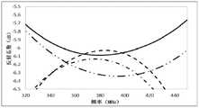
图7为本发明专利的馈电网络的各端口反射系数结果图。Fig. 7 is a graph showing reflection coefficient results of each port of the feed network of the patent of the present invention.
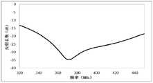
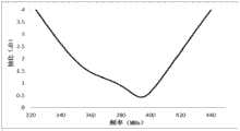
图8为本发明专利的低剖面空气微带天线(不含馈电网络)的反射系数结果图。Fig. 8 is a graph showing reflection coefficient results of the patented low-profile air microstrip antenna (without feeding network) of the present invention.
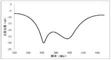
图9为本发明专利的低剖面空气微带天线(含馈电网络)的反射系数结果图。Fig. 9 is a graph showing the reflection coefficient results of the patented low-profile air microstrip antenna (including the feeding network) of the present invention.
图10为本发明专利的低剖面空气微带天线的轴比结果图。Fig. 10 is a diagram of the axial ratio results of the low-profile air microstrip antenna of the patent of the present invention.
图11为本发明专利的低剖面空气微带天线的增益结果图。Fig. 11 is a graph of gain results of the low-profile air microstrip antenna of the patent of the present invention.
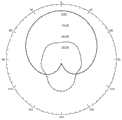
图12为本发明专利的低剖面空气微带天线在366MHz的辐射方向图。Fig. 12 is the radiation pattern of the patented low-profile air microstrip antenna at 366MHz.
图13为本发明专利的低剖面空气微带天线在411MHz的辐射方向图。Fig. 13 is the radiation pattern at 411MHz of the low-profile air microstrip antenna of the patent of the present invention.
图中标号所代表的含义为:1为四周侧壁结构,2为耦合馈电金属板,3为频率调节金属板,4为馈电网络,5为同轴探针,6为顶层金属板,7为直角聚四氟乙烯固定垫片,8为外部金属面,9为馈电网络介质板,10为金属过孔,11为环形混合网络,12为威尔金森功分器,13为圆孔。The meanings of the symbols in the figure are: 1 is the surrounding side wall structure, 2 is the coupling feeding metal plate, 3 is the frequency adjustment metal plate, 4 is the feeding network, 5 is the coaxial probe, 6 is the top metal plate, 7 is a right-angle PTFE fixing gasket, 8 is an external metal surface, 9 is a feed network dielectric plate, 10 is a metal via hole, 11 is a ring hybrid network, 12 is a Wilkinson power divider, and 13 is a round hole .
具体实施方式Detailed ways
结合图1,本发明的一种UHF频段双频圆极化低剖面空气微带天线,包括顶层金属板 6、四周侧壁结构1、频率调节金属板3、耦合馈电金属板2和同轴探针5,其中顶层金属板6设置在四周侧壁结构1的正上方,频率调节金属板3设置在四周侧壁结构1下表面并向内弯折,该频率调节金属板3与四周侧壁结构1相互垂直,四周侧壁结构1的内侧面均为金属面,四周侧壁结构1的外侧面印有外部金属面8,四周侧壁结构1的四个角落的正下方分别设置四个直角聚四氟乙烯固定垫片7,馈电网络介质板9设置在四个直角聚四氟乙烯固定垫片7的下方,馈电网络介质板9的上表面全部印有金属面,馈电网络4印制在馈电网络介质板9的下表面,馈电网络介质板9上开有四个金属过孔10,耦合馈电金属板2位于频率调节金属板3的上方,且与同轴探针5相连,所述同轴探针5的另一端穿过对应的金属过孔10并与馈电网络4的输出端口相连,为天线馈电,所述同轴探针5与馈电网络介质板9的上表面不接触。In conjunction with Fig. 1, a kind of UHF frequency band dual-frequency circularly polarized low-profile air microstrip antenna of the present invention comprises top
所述频率调节金属板3的数量为四个,分别与四周侧壁结构1的四个侧壁相连;耦合馈电金属板2的数量也为四个,耦合馈电金属板2与对应的频率调节金属板3的垂直距离为0.0026λ~0.0137λ,其中λ为工作频率下的自由空间波长;所述同轴探针5的数量为四个。The number of the frequency
所述四周侧壁结构1的长为0.2600λ,厚度为0.0026λ~0.0052λ,高度为0.0137λ~0.0189λ,所述外部金属面8的高度为0.0046λ~0.0189λ,该外部金属面8由底部向上印制在四周侧壁结构1的外侧面,其中λ为工作频率下的自由空间波长。The length of the surrounding
所述馈电网络4有一个输入端和四个输出端,由一个环形混合网络11和两个威尔金森功分器12组成,其中两个威尔金森功分器12位于环形混合网络11的环形内,并分别与环形混合网络11的两个输出端相连,所述馈电网络介质板9为长方体,其长为0.2679λ,宽为0.2679λ,高为0.0013λ,在馈电网络介质板9的上表面金属面上开有四个圆孔13,该四个圆孔13关于馈电网络介质板9的中心对称,圆孔13的半径为同轴探针5半径的2.3倍,该四个圆孔13的圆心分别位于四个金属过孔10的轴线上。The
所述耦合馈电金属板2的长、宽、高分别为0.0520λ~0.1040λ,0.0429λ~0.0689λ,0.0007λ。The length, width and height of the coupling and feeding metal plate 2 are 0.0520λ˜0.1040λ, 0.0429λ˜0.0689λ, and 0.0007λ respectively.
顶层金属板6为长方体,其长为0.2679λ,宽为0.2679λ,高为0.0007λ。The
同轴探针5的半径为0.0013λ,高度为0.0078λ~0.0195λ。The radius of the
所述金属过孔10的半径与同轴探针5的半径相同。The radius of the metal via
所述四个直角聚四氟乙烯固定垫片7的高度相同,均为0.0046λ。The heights of the four right-angled
所述馈电网络介质板9的材料的介电常数为4~15,四周侧壁结构1的材料的介电常数为4~15。The dielectric constant of the material of the feeding network
下面结合实施例进行具体描述:Describe in detail below in conjunction with embodiment:
实施例1Example 1
一种UHF频段双频圆极化低剖面空气微带天线,如图1所示,包括顶层金属板6、四周侧壁结构1、频率调节金属板3、耦合馈电金属板2和同轴探针5,其中顶层金属板6设置在四周侧壁结构1的正上方,频率调节金属板3设置在四周侧壁结构1下表面并向内弯折,该频率调节金属板3与四周侧壁结构1相互垂直,四周侧壁结构1的内侧面均为金属面,四周侧壁结构1的外侧面印有外部金属面8,四周侧壁结构1的四个角落的正下方分别设置四个直角聚四氟乙烯固定垫片7,馈电网络介质板9设置在四个直角聚四氟乙烯固定垫片7的下方,馈电网络介质板9的上表面全部印有金属面,馈电网络4印制在馈电网络介质板9的下表面,馈电网络介质板9上开有四个金属过孔10,耦合馈电金属板2位于频率调节金属板3的上方,且与同轴探针5相连,所述同轴探针5的另一端穿过对应的金属过孔10并与馈电网络4的输出端口相连,为天线馈电,所述同轴探针5与馈电网络介质板9的上表面不接触。天线的两个中心谐振频率分别为366MHz,411MHz,两者的右旋增益分别为3.42dB,3.92dB。A UHF frequency band dual-frequency circularly polarized low-profile air microstrip antenna, as shown in Fig. The
天线结构(不含馈电网络)如图2、图3所示,顶层金属板6设置在四周侧壁结构1的正上方,两者用螺丝进行固定,顶层金属板6的大小为206mm×206mm,厚度为0.5mm。四周侧壁结构1的边长为200mm,厚度为3mm,高度为14.5mm,四周侧壁结构1的内侧面均为金属面,四周侧壁结构1的外侧面印有外部金属面8,其高度为4.5mm。频率调节金属板3用螺丝固定在四周侧壁结构1下表面并向内弯折,该频率调节金属板3的体积为100mm×48mm×0.5mm,耦合馈电金属板2的体积为80mm×43mm×0.5mm,与频率调节金属板3的垂直距离为6.5mm,同轴探针5的半径为1mm。The antenna structure (excluding the feed network) is shown in Figure 2 and Figure 3. The
馈电网络4如图4所示,有一个输入端和四个输出端,由一个环形混合网络11和两个威尔金森功分器12组成,其中两个威尔金森功分器12位于环形混合网络11的环形内,并分别与环形混合网络11的两个输出端相连,所述馈电网络介质板9为长方体,体积为206mm×206mm×1mm,其相对介电常数6,损耗角0.003,在馈电网络介质板9的上表面金属面上开有四个圆孔13,该四个圆孔13关于馈电网络介质板9的中心对称,圆孔13的半径为同轴探针5半径的2.3倍,该四个圆孔13的圆心分别位于四个金属过孔10的轴线上。As shown in Figure 4, the
如图5、图6、图7所示为馈电网络的各个结果图;图5反应出馈电网络具有较宽的带宽,图6反应出馈电网络端口之间的相位之差均约为90°,具有良好的正交性;图7反应馈电网络具有良好的功率分配特性,几乎接近等分。Figure 5, Figure 6, and Figure 7 show the results of the feed network; Figure 5 shows that the feed network has a wide bandwidth, and Figure 6 shows that the phase difference between the ports of the feed network is about 90°, with good orthogonality; Figure 7 shows that the feedback feed network has good power distribution characteristics, which is almost equal.
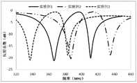
如图8所示为天线(不含馈电网络)的反射系数结果图,如实线所示,从图中反应出天线工作于双频,中心谐振频率分别为366MHz,411MHz;图9所示为天线(含馈电网络)的反射系数结果图,该天线具有良好的阻抗特性,S11≤—10的带宽为22.9%(341MHz—419MHz);图10所示为天线(含馈电网络)的轴比结果图,该天线具有较宽的轴比带宽,AR≤3的轴比带宽为24.6%(335MHz—429MHz);图11所示为天线的增益结果,在366MHz和411MHz处的增益分别是3.42dB,3.92dB;图12所示为天线在366MHz时的辐射方向图;图13所示为天线在411MHz时的辐射方向图。Figure 8 shows the reflection coefficient results of the antenna (excluding the feed network). As shown in the solid line, it is reflected from the figure that the antenna works at dual frequencies, and the center resonant frequencies are 366MHz and 411MHz respectively; Figure 9 shows The reflection coefficient result graph of the antenna (including the feed network), the antenna has good impedance characteristics, and the bandwidth of S11≤-10 is 22.9% (341MHz-419MHz); Figure 10 shows the axis of the antenna (including the feed network) Compared with the result figure, the antenna has a wider axial ratio bandwidth, and the axial ratio bandwidth of AR≤3 is 24.6% (335MHz—429MHz); Figure 11 shows the gain results of the antenna, and the gains at 366MHz and 411MHz are 3.42 dB, 3.92dB; Figure 12 shows the radiation pattern of the antenna at 366MHz; Figure 13 shows the radiation pattern of the antenna at 411MHz.
实施例2Example 2
结合图1或8,在实施例1的基础上进一步改进可以得到一种双频圆极化低剖面空气微带天线,如图1所示,包括顶层金属板6、四周侧壁结构1、频率调节金属板3、耦合馈电金属板2和同轴探针5,其中顶层金属板6设置在四周侧壁结构1的正上方,频率调节金属板3设置在四周侧壁结构1下表面并向内弯折,该频率调节金属板3与四周侧壁结构1相互垂直,四周侧壁结构1的内侧面均为金属面,四周侧壁结构1的外侧面印有外部金属面8,四周侧壁结构1的四个角落的正下方分别设置四个直角聚四氟乙烯固定垫片7,馈电网络介质板9设置在四个直角聚四氟乙烯固定垫片7的下方,馈电网络介质板9的上表面全部印有金属面,馈电网络4印制在馈电网络介质板9的下表面,馈电网络介质板9上开有四个金属过孔10,耦合馈电金属板2位于频率调节金属板3的上方,且与同轴探针5相连,所述同轴探针5的另一端穿过对应的金属过孔10并与馈电网络4的输出端口相连,为天线馈电,所述同轴探针5与馈电网络介质板9的上表面不接触。In conjunction with Fig. 1 or 8, further improvement on the basis of
天线结构(不含馈电网络)如图2、图3所示,顶层金属板6设置在四周侧壁结构1的正上方,两者用螺丝进行固定,顶层金属板6的大小为206mm×206mm,厚度为0.5mm。四周侧壁结构1的边长为200mm,厚度为2mm,高度为9.5mm,四周侧壁结构1的内侧面均为金属面,四周侧壁结构1的外侧面印有外部金属面8,其高度为3.5mm。频率调节金属板3用螺丝固定在四周侧壁结构1下表面并向内弯折,该频率调节金属板3的体积为100mm×48mm×0.5mm,耦合馈电金属板2的体积为80mm×43mm×0.5mm,与频率调节金属板3的垂直距离为3.5mm,同轴探针5的半径为1mm。The antenna structure (excluding the feed network) is shown in Figure 2 and Figure 3. The
馈电网络4如图4所示,有一个输入端和四个输出端,由一个环形混合网络11和两个威尔金森功分器12组成,其中两个威尔金森功分器12位于环形混合网络11的环形内,并分别与环形混合网络11的两个输出端相连,所述馈电网络介质板9为长方体,体积为206mm×206mm×1mm,其相对介电常数6,损耗角0.003,在馈电网络介质板9的上表面金属面上开有四个圆孔13,该四个圆孔13关于馈电网络介质板9的中心对称,圆孔13的半径为同轴探针5半径的2.3倍,该四个圆孔13的圆心分别位于四个金属过孔10的轴线上,此时的反射系数结果曲线如图8中点画线所示,其工作频率向高频偏移。As shown in Figure 4, the
实施例3Example 3
结合图1或8,在实施例1的基础上进一步改进可以得到一种双频圆极化低剖面空气微带天线,如图1所示,包括顶层金属板6、四周侧壁结构1、频率调节金属板3、耦合馈电金属板2和同轴探针5,其中顶层金属板6设置在四周侧壁结构1的正上方,频率调节金属板3设置在四周侧壁结构1下表面并向内弯折,该频率调节金属板3与四周侧壁结构1相互垂直,四周侧壁结构1的内侧面均为金属面,四周侧壁结构1的外侧面印有外部金属面8,四周侧壁结构1的四个角落的正下方分别设置四个直角聚四氟乙烯固定垫片7,馈电网络介质板9设置在四个直角聚四氟乙烯固定垫片7的下方,馈电网络介质板9的上表面全部印有金属面,馈电网络4印制在馈电网络介质板9的下表面,馈电网络介质板9上开有四个金属过孔10,耦合馈电金属板2位于频率调节金属板3的上方,且与同轴探针5相连,所述同轴探针5的另一端穿过对应的金属过孔10并与馈电网络4的输出端口相连,为天线馈电,所述同轴探针5与馈电网络介质板9的上表面不接触。In conjunction with Fig. 1 or 8, further improvement on the basis of
天线结构(不含馈电网络)如图2、图3所示,顶层金属板6设置在四周侧壁结构1的正上方,两者用螺丝进行固定,顶层金属板6的大小为206mm×206mm,厚度为0.5mm。四周侧壁结构1的边长为200mm,厚度为4mm,高度为18.5mm,四周侧壁结构1的内侧面均为金属面,四周侧壁结构1的外侧面印有外部金属面8,其高度为13.5mm。频率调节金属板3用螺丝固定在四周侧壁结构1下表面并向内弯折,该频率调节金属板3的体积为100mm×48mm×0.5mm,耦合馈电金属板2的体积为80mm×43mm×0.5mm,与频率调节金属板3的垂直距离为8.5mm,同轴探针5的半径为1mm。The antenna structure (excluding the feed network) is shown in Figure 2 and Figure 3. The
馈电网络4如图4所示,有一个输入端和四个输出端,由一个环形混合网络11和两个威尔金森功分器12组成,其中两个威尔金森功分器12位于环形混合网络11的环形内,并分别与环形混合网络11的两个输出端相连,所述馈电网络介质板9为长方体,体积为206mm×206mm×1mm,其相对介电常数6,损耗角0.003,在馈电网络介质板9的上表面金属面上开有四个圆孔13,该四个圆孔13关于馈电网络介质板9的中心对称,圆孔13的半径为同轴探针5半径的2.3倍,该四个圆孔13的圆心分别位于四个金属过孔10的轴线上,此时的反射系数结果曲线如图8中虚线所示,其工作频率向低频偏移。As shown in Figure 4, the
由上述可知,本专利中采用空气微带天线的形式,同时采用耦合馈电的方式,大大提高了天线的带宽,天线采用四周均折叠的技术使天线小型化,天线整体高度为0.019λ,其中λ为工作频率下的自由空间波长,采用馈电网络使之产生四个相位相互正交的信号分别给天线的四个端口馈电,使天线的极化方式为圆极化,采用四馈的方式可以使得天线获得较高的极化纯度和较宽的轴比带宽,通过在四周侧壁结构的外侧面印制部分金属面的方式使天线产生了另一个谐振频率,从而在不改变原有天线体积的基础上使得天线能够同时工作在双频点,本发明专利的UHF频段双频圆极化低剖面空气微带天线同时实现了低剖面,圆极化,宽频带以及高增益的特性,使之能广泛的应用于通信,医疗等领域。As can be seen from the above, this patent adopts the form of an air microstrip antenna, and at the same time adopts the coupling feeding method, which greatly improves the bandwidth of the antenna. The antenna adopts the technology of folding all around to make the antenna miniaturized. The overall height of the antenna is 0.019λ, where λ is the free-space wavelength at the working frequency. The feed network is used to generate four signals with mutually orthogonal phases to feed the four ports of the antenna respectively, so that the polarization mode of the antenna is circular polarization, and the four-feed The method can make the antenna obtain higher polarization purity and wider axial ratio bandwidth. By printing part of the metal surface on the outer side of the surrounding side wall structure, the antenna produces another resonant frequency, thus without changing the original On the basis of the antenna volume, the antenna can work at dual frequency points at the same time. The patented UHF frequency band dual-frequency circular polarization low-profile air microstrip antenna simultaneously realizes the characteristics of low profile, circular polarization, wide frequency band and high gain. So that it can be widely used in communication, medical and other fields.
Claims (10)
Translated fromChinesePriority Applications (1)
| Application Number | Priority Date | Filing Date | Title |
|---|---|---|---|
| CN201310444387.5ACN103500876B (en) | 2013-09-26 | 2013-09-26 | Air microstrip antenna with UHF (Ultra High Frequency) double-band circular polarization low profile |
Applications Claiming Priority (1)
| Application Number | Priority Date | Filing Date | Title |
|---|---|---|---|
| CN201310444387.5ACN103500876B (en) | 2013-09-26 | 2013-09-26 | Air microstrip antenna with UHF (Ultra High Frequency) double-band circular polarization low profile |
Publications (2)
| Publication Number | Publication Date |
|---|---|
| CN103500876Atrue CN103500876A (en) | 2014-01-08 |
| CN103500876B CN103500876B (en) | 2015-05-13 |
Family
ID=49866059
Family Applications (1)
| Application Number | Title | Priority Date | Filing Date |
|---|---|---|---|
| CN201310444387.5AActiveCN103500876B (en) | 2013-09-26 | 2013-09-26 | Air microstrip antenna with UHF (Ultra High Frequency) double-band circular polarization low profile |
Country Status (1)
| Country | Link |
|---|---|
| CN (1) | CN103500876B (en) |
Cited By (4)
| Publication number | Priority date | Publication date | Assignee | Title |
|---|---|---|---|---|
| CN105811102A (en)* | 2016-05-23 | 2016-07-27 | 中国电子科技集团公司第五十四研究所 | Miniature low-profile broadband dual-circular-polarization microstrip antenna |
| CN107978857A (en)* | 2017-11-16 | 2018-05-01 | 西安电子科技大学 | A kind of micro-strip paster antenna of high phase place central stabilizer degree aperture-coupled |
| CN108539438A (en)* | 2018-05-24 | 2018-09-14 | 广东曼克维通信科技有限公司 | UHF dual polarized antennas |
| CN114914689A (en)* | 2022-05-12 | 2022-08-16 | 中国电子科技集团公司第五十四研究所 | Low-profile common-caliber dual-band circularly polarized microstrip antenna |
Citations (5)
| Publication number | Priority date | Publication date | Assignee | Title |
|---|---|---|---|---|
| US6091365A (en)* | 1997-02-24 | 2000-07-18 | Telefonaktiebolaget Lm Ericsson | Antenna arrangements having radiating elements radiating at different frequencies |
| CN2927347Y (en)* | 2006-07-12 | 2007-07-25 | 江苏瑞福智能科技有限公司 | UHF wafer polarized microstrip antenna |
| CN201146246Y (en)* | 2008-01-17 | 2008-11-05 | 华南理工大学 | Circularly Polarized Reader Array Antenna for Radio Frequency Identification Based on Ring Feed Network |
| CN201435450Y (en)* | 2009-06-30 | 2010-03-31 | 华南理工大学 | Polarized Reconfigurable RFID Circularly Polarized Reader Antenna |
| CN102904070A (en)* | 2012-09-29 | 2013-01-30 | 航天恒星科技有限公司 | A multi-frequency point satellite navigation terminal antenna |
- 2013
- 2013-09-26CNCN201310444387.5Apatent/CN103500876B/enactiveActive
Patent Citations (5)
| Publication number | Priority date | Publication date | Assignee | Title |
|---|---|---|---|---|
| US6091365A (en)* | 1997-02-24 | 2000-07-18 | Telefonaktiebolaget Lm Ericsson | Antenna arrangements having radiating elements radiating at different frequencies |
| CN2927347Y (en)* | 2006-07-12 | 2007-07-25 | 江苏瑞福智能科技有限公司 | UHF wafer polarized microstrip antenna |
| CN201146246Y (en)* | 2008-01-17 | 2008-11-05 | 华南理工大学 | Circularly Polarized Reader Array Antenna for Radio Frequency Identification Based on Ring Feed Network |
| CN201435450Y (en)* | 2009-06-30 | 2010-03-31 | 华南理工大学 | Polarized Reconfigurable RFID Circularly Polarized Reader Antenna |
| CN102904070A (en)* | 2012-09-29 | 2013-01-30 | 航天恒星科技有限公司 | A multi-frequency point satellite navigation terminal antenna |
Non-Patent Citations (2)
| Title |
|---|
| KA-LEUNG LAU等: ""A Wide-Band Circularly Polarized L-Probe Coupled Patch Antenna for Dual-Band Operation"", 《ANTENNAS AND PROPAGATION》, vol. 53, no. 8, 8 August 2005 (2005-08-08)* |
| 王昊等: ""用馈电校正优化设计双馈点圆极化微带天线"", 《南京理工大学学报》, vol. 31, no. 1, 28 February 2007 (2007-02-28)* |
Cited By (7)
| Publication number | Priority date | Publication date | Assignee | Title |
|---|---|---|---|---|
| CN105811102A (en)* | 2016-05-23 | 2016-07-27 | 中国电子科技集团公司第五十四研究所 | Miniature low-profile broadband dual-circular-polarization microstrip antenna |
| CN105811102B (en)* | 2016-05-23 | 2018-06-12 | 中国电子科技集团公司第五十四研究所 | A kind of miniaturization low section broadband double-circle polarization microstrip antenna |
| CN107978857A (en)* | 2017-11-16 | 2018-05-01 | 西安电子科技大学 | A kind of micro-strip paster antenna of high phase place central stabilizer degree aperture-coupled |
| CN108539438A (en)* | 2018-05-24 | 2018-09-14 | 广东曼克维通信科技有限公司 | UHF dual polarized antennas |
| CN108539438B (en)* | 2018-05-24 | 2020-11-13 | 广东曼克维通信科技有限公司 | UHF dual polarized antenna |
| CN114914689A (en)* | 2022-05-12 | 2022-08-16 | 中国电子科技集团公司第五十四研究所 | Low-profile common-caliber dual-band circularly polarized microstrip antenna |
| CN114914689B (en)* | 2022-05-12 | 2024-01-23 | 中国电子科技集团公司第五十四研究所 | Low-profile common-caliber dual-band circularly polarized microstrip antenna |
Also Published As
| Publication number | Publication date |
|---|---|
| CN103500876B (en) | 2015-05-13 |
Similar Documents
| Publication | Publication Date | Title |
|---|---|---|
| CN105811102B (en) | A kind of miniaturization low section broadband double-circle polarization microstrip antenna | |
| US8779988B2 (en) | Surface mount device multiple-band antenna module | |
| CN108649325A (en) | A kind of wide band high-gain millimeter wave dielectric resonant antenna array | |
| CN101246997B (en) | Feed network of broadband array antenna | |
| CN113131197B (en) | Dual-polarized antenna unit and base station antenna | |
| CN108448234B (en) | Three-frequency-band MIMO terminal antenna based on composite left-right-hand transmission line structure | |
| CN107785661A (en) | A kind of uncoupling array antenna based on double frequency Meta Materials | |
| WO2019062445A1 (en) | Multi-polarized radiation oscillator and antenna | |
| CN104953256A (en) | Broadband circularly-polarized panel array antenna | |
| US11557839B2 (en) | Double frequency vertical polarization antenna and television | |
| CN205621858U (en) | Two circular polarization microstrip antenna of miniaturized low section broadband | |
| CN102904009A (en) | A Small Wide Bandwidth Beam Circularly Polarized Microstrip Antenna | |
| CN104795638A (en) | Dual-band circularly-polarized co-aperture microstrip antenna | |
| CN103500876B (en) | Air microstrip antenna with UHF (Ultra High Frequency) double-band circular polarization low profile | |
| CN103178341B (en) | Indoor high-speed communication antenna of wide-beam Q-band millimeter waves | |
| CN109560388B (en) | Millimeter wave broadband circularly polarized antenna based on substrate integrated waveguide horn | |
| CN105490036A (en) | Series-feed and shunt-feed combination filtering microstrip array antenna | |
| CN102646859A (en) | A low-profile double-layer printed ultra-wideband antenna | |
| CN104332704A (en) | Handset terminal antenna for mobile satellite communication system | |
| CN109742515B (en) | A millimeter wave circularly polarized antenna for mobile terminals | |
| CN201163659Y (en) | Plane inverse F shape antenna with serpentine curve structure | |
| CN108666750A (en) | Substrate integration wave-guide circular polarized antenna | |
| CN105186127B (en) | A kind of more back bars expand the Low-profile bilayer printing ultra-wideband antenna of frequency band | |
| CN113690621B (en) | Miniaturized high efficiency bluetooth antenna based on multilayer PCB board | |
| Khabba et al. | Beam-steering millimeter-wave antenna array for fifth generation smartphone applications |
Legal Events
| Date | Code | Title | Description |
|---|---|---|---|
| C06 | Publication | ||
| PB01 | Publication | ||
| C10 | Entry into substantive examination | ||
| SE01 | Entry into force of request for substantive examination | ||
| C14 | Grant of patent or utility model | ||
| GR01 | Patent grant |