CN103492982A - Interactive display device - Google Patents
Interactive display deviceDownload PDFInfo
- Publication number
- CN103492982A CN103492982ACN201280000880.1ACN201280000880ACN103492982ACN 103492982 ACN103492982 ACN 103492982ACN 201280000880 ACN201280000880 ACN 201280000880ACN 103492982 ACN103492982 ACN 103492982A
- Authority
- CN
- China
- Prior art keywords
- detection
- detection light
- image
- distance
- area
- Prior art date
- Legal status (The legal status is an assumption and is not a legal conclusion. Google has not performed a legal analysis and makes no representation as to the accuracy of the status listed.)
- Pending
Links
Images


Classifications
- G—PHYSICS
- G06—COMPUTING OR CALCULATING; COUNTING
- G06F—ELECTRIC DIGITAL DATA PROCESSING
- G06F3/00—Input arrangements for transferring data to be processed into a form capable of being handled by the computer; Output arrangements for transferring data from processing unit to output unit, e.g. interface arrangements
- G06F3/01—Input arrangements or combined input and output arrangements for interaction between user and computer
- G06F3/03—Arrangements for converting the position or the displacement of a member into a coded form
- G06F3/041—Digitisers, e.g. for touch screens or touch pads, characterised by the transducing means
- G06F3/0416—Control or interface arrangements specially adapted for digitisers
- G—PHYSICS
- G06—COMPUTING OR CALCULATING; COUNTING
- G06F—ELECTRIC DIGITAL DATA PROCESSING
- G06F3/00—Input arrangements for transferring data to be processed into a form capable of being handled by the computer; Output arrangements for transferring data from processing unit to output unit, e.g. interface arrangements
- G06F3/01—Input arrangements or combined input and output arrangements for interaction between user and computer
- G06F3/03—Arrangements for converting the position or the displacement of a member into a coded form
- G06F3/041—Digitisers, e.g. for touch screens or touch pads, characterised by the transducing means
- G06F3/042—Digitisers, e.g. for touch screens or touch pads, characterised by the transducing means by opto-electronic means
- G06F3/0428—Digitisers, e.g. for touch screens or touch pads, characterised by the transducing means by opto-electronic means by sensing at the edges of the touch surface the interruption of optical paths, e.g. an illumination plane, parallel to the touch surface which may be virtual
Landscapes
- Engineering & Computer Science (AREA)
- General Engineering & Computer Science (AREA)
- Theoretical Computer Science (AREA)
- Human Computer Interaction (AREA)
- Physics & Mathematics (AREA)
- General Physics & Mathematics (AREA)
- Length Measuring Devices By Optical Means (AREA)
- Position Input By Displaying (AREA)
Abstract
Translated fromChinese
Description
Translated fromChinese技术领域technical field
本发明涉及在由投影仪等投影图像的屏幕上用人的手指等进行触摸,由此能够交互地进行控制的装置。The present invention relates to a device that can be interactively controlled by touching a screen projected by a projector or the like with a human finger or the like.
背景技术Background technique
已出现了搭载有触摸面板的计算机,所述触摸面板能够用手指等对画面上的对象进行操作。由于能够进行直观的操作,因此迅速地普及开来。但是,当用大画面来实现触摸面板时,触摸面板的成本增加,操作也变得困难。Computers equipped with a touch panel capable of operating objects on a screen with a finger or the like have appeared. Since it can be operated intuitively, it is rapidly gaining popularity. However, when the touch panel is realized with a large screen, the cost of the touch panel increases and the operation becomes difficult.
因此,开发出如下这样的触摸屏装置:该触摸屏装置将投影仪和照相机组合起来,用照相机检测由投影仪投射的画面上的笔或手指的位置,对计算机进行操作。Therefore, a touch panel device has been developed that combines a projector and a camera, and uses the camera to detect the position of a pen or finger on a screen projected by the projector to operate a computer.
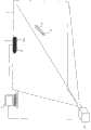
图1示出了专利文献1中公开的触摸屏装置。投影仪14与PC 2连接。投影仪14根据PC 2的控制,向检测区域4进行投射来显示图像。FIG. 1 shows a touch screen device disclosed in
在检测区域4的上部设置有检测单元6。在检测单元6中设置有第一检测器8和第二检测器10。第一检测器8具有红外光照射器8a、红外光检测器8b。另外,在检测区域4的左右端及下端设置有红外光反射器12。红外光检测器8b检测由红外光反射器12反射的红外光。同样,第二检测器10具有红外光照射器10a和红外光检测器10b。In the upper part of the detection area 4 a
此处,在检测区域中存在笔等检测对象物时,红外光检测器8b、10b检测到检测对象物。另外,红外光反射器12构成为朝向红外光入射的方向进行反射,因此,红外光检测器8b、10b能够确定相对于检测对象物的角度。因此,PC 2结合红外光检测器8b,10b的检测输出,由此来确定检测对象物的位置。Here, when a detection target object such as a pen exists in the detection area, the infrared light detectors 8b and 10b detect the detection target object. In addition, since the infrared light reflector 12 is configured to reflect toward the direction in which infrared light is incident, the infrared light detectors 8 b and 10 b can specify the angle with respect to the object to be detected. Therefore, the PC 2 combines the detection outputs of the infrared light detectors 8b, 10b to determine the position of the detection object.
PC 2进行如下控制:根据检测到的检测对象物的移动,例如在检测区域4的对应的位置处进行描绘。由此,通过投影仪14进行描绘。The PC 2 performs control of, for example, drawing at a corresponding position in the detection area 4 based on the detected movement of the detection target. Thus, rendering is performed by the
如上地,无需使用特别的笔等即可进行交互的显示控制。As above, interactive display control can be performed without using a special pen or the like.
图2示出了专利文献2中记载的触摸屏装置。投影仪14根据PC 2的控制,朝向检测区域4进行投射来显示图像。FIG. 2 shows a touch panel device described in
在检测区域4的上部设置有检测单元6。在检测单元6中设置有红外光检测器8b和红外光检测器10b。用户使电子笔16在检测区域4中移动。在电子笔16的笔头设置有红外光照射器18。因此,红外光检测器8b、10b能够检测相对于电子笔16的角度。PC 2接收来自红外光检测器8b、10b的输出,确定电子笔16的位置。In the upper part of the detection area 4 a
PC 2进行如下控制:根据检测到的电子笔16的移动,例如在检测区域4的对应的位置处进行描绘。由此,通过投影仪14进行描绘。The
【现有技术文献】[Prior Art Literature]
【专利文献】【Patent Literature】
【专利文献1】日本特开2011-253286[Patent Document 1] Japanese Patent Laid-Open No. 2011-253286
【专利文献2】日本特开2011-126225[Patent Document 2] Japanese Patent Laid-Open No. 2011-126225
【发明概要】【Invention Outline】
【发明所要解决的课题】【Problem to be solved by the invention】
但是,在专利文献1的装置中需要红外光反射器12。因此,在构成为具有所配备的红外光反射器12的触摸屏装置的情况下,存在导致装置大型化的问题。另外,在构成为每次都设置红外光反射器12而进行使用的装置的情况下,必须要携带着红外光反射器12,存在操作复杂的问题。However, the device of
另外,在专利文献2的装置中,需要电子笔16等特殊的设备。因此,在丢失了电子笔16的情况下,存在不容易找到替代物的问题。In addition, in the device of
本发明的目的在于解决上述这样的问题点,从而提供一种无需体积大的红外光反射器和电子笔那样的特殊设备即可进行交互控制的触摸屏装置。The purpose of the present invention is to solve the above-mentioned problems, thereby providing a touch screen device capable of interactive control without the need for a bulky infrared light reflector and special equipment such as an electronic pen.
【用于解决课题的手段】【Means used to solve the problem】
(1)(2)(3)本发明的交互显示装置具有:检测区域用部件,其用于配置在检测区域中,具有对检测光进行反射的检测光反射面;检测光照射部,其被设置为向所述检测区域照射检测光;深度传感器,其设置在由所述检测光反射面反射的检测光不会入射到的位置,接收由位于检测区域中的检测对象物反射的检测光以及在所述检测光反射面的周围反射的检测光,取得离各自的距离;位置计算单元,其根据深度传感器的输出,计算检测对象物在所述检测区域中的位置;影像显示部,其用于在所述检测光反射面上显示影像;以及影像控制单元,其根据由所述位置计算单元计算出的检测对象物的位置,使得由影像显示部显示在所述检测光反射面上的影像发生变化。(1) (2) (3) The interactive display device of the present invention has: a member for detection area, which is arranged in the detection area, and has a detection light reflection surface that reflects detection light; The detection area is arranged to irradiate the detection light; the depth sensor is installed at a position where the detection light reflected by the detection light reflection surface does not enter, receives the detection light reflected by the detection target object located in the detection area, and The detection light reflected around the detection light reflection surface obtains the respective distances; the position calculation unit calculates the position of the detection target object in the detection area based on the output of the depth sensor; the image display unit uses displaying an image on the detection light reflection surface; and an image control unit that displays an image on the detection light reflection surface by the image display unit based on the position of the detection object calculated by the position calculation unit change.
因此,无需使用红外光反射器和电子笔那样的特殊设备,即可进行交互控制。Therefore, interactive control is possible without using special equipment such as infrared light reflectors and electronic pens.
(4)本发明的交互显示装置的特征在于,位置计算单元基于由检测对象物反射的检测光的检测距离,而且基于从检测对象物反射并由所述检测光反射面进一步反射的检测光的检测距离,判断检测对象物触摸到所述检测光反射面的情况。(4) The interactive display device of the present invention is characterized in that the position calculation means is based on the detection distance of the detection light reflected by the detection object, and also based on the detection distance of the detection light reflected from the detection object and further reflected by the detection light reflection surface. The detection distance is used to judge the situation that the detection object touches the detection light reflecting surface.
因此,能够根据检测对象物接触了检测光反射面的情况来进行处理。Therefore, processing can be performed according to the fact that the object to be detected has come into contact with the detection light reflecting surface.
(5)本发明的交互显示装置的特征在于,还具有:红外图像摄像部,其被设置为对检测区域的红外图像进行摄像;以及距离图像生成单元,其根据所述检测距离生成距离图像,位置计算单元根据所述红外图像和所述距离图像中的检测对象物的图像的偏差,判断检测对象物触摸到所述检测光反射面的情况。(5) The interactive display device of the present invention is characterized in that it further has: an infrared image capturing unit configured to capture an infrared image of the detection area; and a distance image generating unit that generates a distance image based on the detection distance, The position calculating unit judges that the detection target object touches the detection light reflection surface based on the deviation between the infrared image and the detection target object image in the range image.
因此,能够根据检测对象物接触了检测光反射面的情况来进行处理。Therefore, it is possible to perform processing according to the fact that the object to be detected has come into contact with the detection light reflecting surface.
(6)本发明的交互显示装置的特征在于,检测光为红外光。(6) The interactive display device of the present invention is characterized in that the detection light is infrared light.
因此,能够使得交互控制用的检测光不能看到。Therefore, the detection light for interactive control can be made invisible.
(7)本发明的触摸位置检测方法的特征在于,将具有对检测光进行反射的检测光反射面的检测区域用部件配置在检测区域中,将检测光照射部配置成向所述检测区域照射检测光,在由所述检测光反射面反射的检测光不会入射到的位置处,接收由位于检测区域中的检测对象物反射的检测光以及在所述检测光反射面的周围反射的检测光,计算离各自的距离,根据所述计算出的距离,计算检测对象物在所述检测区域中的位置。(7) The touch position detection method of the present invention is characterized in that a member for the detection area having a detection light reflecting surface that reflects the detection light is arranged in the detection area, and the detection light irradiation unit is arranged to irradiate the detection area to the detection area. The detection light receives the detection light reflected by the detection target object located in the detection area and the detection light reflected around the detection light reflection surface at a position where the detection light reflected by the detection light reflection surface does not enter. The light calculates the distance from each, and calculates the position of the detection target object in the detection area based on the calculated distance.
因此,无需使用红外光反射器和电子笔那样的特殊设备,即可进行交互控制。Therefore, interactive control is possible without using special equipment such as infrared light reflectors and electronic pens.
(8)(9)(10)本发明的交互显示装置具有:检测区域用部件,其用于配置在检测区域中,具有吸收检测光的检测光吸收面;检测光照射部,其被配置成向所述检测区域照射检测光;深度传感器,其接收由位于检测区域中的检测对象物反射的检测光以及在所述检测光吸收面的周围反射的检测光,取得离各自的距离;位置计算单元,其根据深度传感器的输出,计算检测对象物在所述检测区域中的位置;影像显示部,其用于在所述检测光吸收面上显示影像;以及影像控制单元,其根据由所述位置计算单元计算出的检测对象物的位置,使得由影像显示部显示在所述检测光反射面上的影像发生变化。(8) (9) (10) The interactive display device of the present invention has: a member for the detection area, which is arranged in the detection area, and has a detection light absorption surface that absorbs the detection light; and a detection light irradiation unit, which is arranged to irradiating detection light to the detection area; a depth sensor that receives the detection light reflected by the detection object located in the detection area and the detection light reflected around the detection light absorbing surface, and obtains the distance from each; position calculation A unit that calculates the position of the detection object in the detection area based on the output of the depth sensor; an image display unit that displays an image on the detection light absorption surface; and an image control unit that uses the The position of the object to be detected calculated by the position calculation unit changes the image displayed on the detection light reflecting surface by the image display unit.
因此,无需使用红外光反射器和电子笔那样的特殊设备,即可进行交互控制。Therefore, interactive control is possible without using special equipment such as infrared light reflectors and electronic pens.
(11)本发明的交互显示装置的特征在于,还具有:红外图像摄像部,其被设置为对检测区域的红外图像进行摄像;以及距离图像生成单元,其根据检测距离生成距离图像,位置计算单元根据所述红外图像和所述距离图像中的检测对象物的图像的偏差,判断检测对象物触摸到所述检测光吸收面的情况。(11) The interactive display device of the present invention is characterized in that it further has: an infrared image capturing unit configured to capture an infrared image of the detection area; and a distance image generation unit that generates a distance image based on the detection distance and calculates the position. The unit judges that the detection object touches the detection light absorption surface according to the deviation between the infrared image and the image of the detection object in the distance image.
因此,能够根据检测对象物接触了检测光吸收面的情况来进行处理。Therefore, processing can be performed according to the fact that the object to be detected has come into contact with the detection light absorbing surface.
(12)本发明的交互显示装置的特征在于,影像显示部为投影仪。(12) In the interactive display device of the present invention, the video display unit is a projector.
因此,能够通过投影仪来进行显示。Therefore, it is possible to display by a projector.
(13)本发明的交互显示装置的特征在于,影像显示部为显示器,检测区域用部件配置在显示器的表面。(13) The interactive display device of the present invention is characterized in that the video display unit is a display, and the detection region member is arranged on a surface of the display.
因此,即使不使用透明电极等,也能够实现触摸面板。Therefore, a touch panel can be realized without using transparent electrodes or the like.
在实施方式中,“位置计算单元”对应于图6的步骤S5、或图15的步骤S5。In the embodiment, the "position calculation unit" corresponds to step S5 in FIG. 6 or step S5 in FIG. 15 .
在实施方式中,“影像控制单元”对应于图6的步骤S6、或图15的步骤S6。In the embodiment, the "image control unit" corresponds to step S6 in FIG. 6 or step S6 in FIG. 15 .
“程序”的概念不仅包含能够由CPU直接执行的程序,还包含源格式的程序、进行了压缩处理的程序、被加密的程序等。The concept of "program" includes not only a program that can be directly executed by the CPU, but also a program in a source format, a compressed program, an encrypted program, and the like.
附图说明Description of drawings
图1是示出以往的交互显示装置的图。FIG. 1 is a diagram showing a conventional interactive display device.
图2是示出以往的交互显示装置的图。FIG. 2 is a diagram showing a conventional interactive display device.
图3是示出本发明的一个实施方式的交互显示装置的外观的图。FIG. 3 is a diagram showing the appearance of an interactive display device according to an embodiment of the present invention.
图4是示出一个实施方式的交互显示装置的原理的图。FIG. 4 is a diagram showing the principle of an interactive display device according to one embodiment.
图5是交互显示装置的硬件结构。Fig. 5 is the hardware structure of the interactive display device.
图6是控制程序56的流程图。FIG. 6 is a flowchart of the
图7是在检测区域中不存在手指时的距离图像的例子。FIG. 7 is an example of a distance image when no finger exists in the detection area.
图8是在检测区域中存在手指时的距离图像的例子。FIG. 8 is an example of a distance image when a finger exists in the detection area.
图9是手指触摸到红外光反射部件26时的距离图像的例子。FIG. 9 is an example of a distance image when a finger touches the infrared
图10是示出产生反射图像的原理的图。Fig. 10 is a diagram showing the principle of generating a reflected image.
图11是手指的距离图像的例子。FIG. 11 is an example of a distance image of a finger.
图12是示出基于坐标变换的位置确定手法的图。FIG. 12 is a diagram showing a method of specifying a position by coordinate transformation.
图13是将红外光反射部件26配置成格子状(线状)时的例子。FIG. 13 is an example when the infrared
图14是第二实施方式的控制程序56的流程图。FIG. 14 is a flowchart of the
图15是第二实施方式的控制程序56的流程图。FIG. 15 is a flowchart of the
图16是不存在手指时与存在手指时的距离图像的例子。FIG. 16 is an example of a distance image when there is no finger and when there is a finger.
图17是示出距离图像中的差分图像的例子及提取出的轮廓的图。FIG. 17 is a diagram showing an example of a difference image in a range image and extracted contours.
图18是示出红外图像中的轮廓的图。FIG. 18 is a diagram showing contours in an infrared image.
图19是用于对距离图像的轮廓与红外图像的轮廓进行比较的图。FIG. 19 is a graph for comparing the contours of the distance image and the contours of the infrared image.
图20是用于对距离图像的轮廓前端与红外图像的轮廓前端进行比较的图。FIG. 20 is a diagram for comparing the contour front of the distance image with the contour front of the infrared image.
图21是其他实施方式的红外光反射部件26的例子。FIG. 21 is an example of an infrared
具体实施方式Detailed ways
1.第一实施方式1. First Embodiment
1.1整体结构1.1 Overall structure
图3示出了本发明的一个实施方式的触摸屏装置的外观。投影仪22、检测单元24与PC 20连接。在检测区域中,设置有红外光反射部件26作为检测区域用部件。红外光反射部件26的表面是对红外光进行反射的红外光反射面。FIG. 3 shows the appearance of a touch panel device according to one embodiment of the present invention.
作为红外光反射部件26,需要对深度照相机30照射的红外光进行反射(如后所述,以不能测量距离的程度进行反射)。例如,可使用对红外线进行反射的层压聚酯膜(3M Scotchtint玻璃膜、Multilayer nano 80S(商标))。The infrared
投影仪22根据PC 20的控制,在红外光反射部件26的表面投射影像。The
检测单元24具有红外光照射器28及深度照相机30。深度照相机30输出离与各像素对应的区域的距离。如图4所示,接收从红外光照射器28发出并由检测对象物32反射的红外光,能够得到离检测对象物32的距离。另外,在红外光反射部件26中,红外光发生反射且不会返回到深度照相机30,因此成为不能测量距离的区域。另外,在红外光反射部件26的外侧,由于红外光进行漫反射,因此能够得到距离。The detection unit 24 has an infrared light irradiator 28 and a
另外,如图4所示,检测单元24构成为,红外光照射器28、深度照相机30相对于红外光反射部件26的高度为20cm~30cm左右。In addition, as shown in FIG. 4 , the detecting unit 24 is configured such that the height of the infrared light irradiator 28 and the
1.2硬件结构1.2 Hardware structure
图5示出了触摸屏装置的硬件结构。与CPU 42连接着存储器44、深度照相机30、CD-ROM驱动器48、硬盘50、投影仪22。FIG. 5 shows the hardware structure of the touch screen device. A
在硬盘50中记录有WINDOWS(商标)等操作系统(OS)54、控制程序56。控制程序56与OS 54协作地发挥其功能。OS 54、控制程序56将记录在CD-ROM 52中的内容经由CD-ROM驱动器48安装到硬盘50中。An operating system (OS) 54 such as WINDOWS (trademark) and a
1.3处理流程图1.3 Processing flow chart
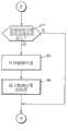
图6示出了控制程序56的流程图。CPU 42从深度照相机30取入每个像素的距离数据(步骤S1)。在该实施方式中,深度照相机的摄像范围是比作为检测区域的红外光反射部件26稍大的范围。FIG. 6 shows a flow chart of the
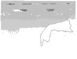
CPU 42根据每个取入的像素的距离数据,生成根据距离附上了浓度差的距离图像(灰度图像)(步骤S2)。图7示出了这样生成的距离图像的例子。在该实施方式中,距离越近浓度越浓,距离越远浓度越淡。The
由于红外光不会从红外光反射部件26返回,因此成为无限远的距离(不能测量),如图7的区域100所示,成为浅色。另外,在红外光反射部件26的周围,由于红外光进行漫反射,因此能够进行测量。因此,如区域102所示,表现为比区域100深的颜色。Since the infrared light does not return from the infrared
由此,能够将检测区域(即存在红外光反射部件26的区域)及其以外的区域作为图像来进行区分。也就是说,CPU 42确定检测区域的4个角的坐标(像素的位置)。Thereby, it is possible to distinguish the detection region (that is, the region where the infrared
接着,CPU 42判断在检测区域内是否存在检测对象物(步骤S3)。在该实施方式中,如果反射了红外光,则能够进行检测,因此,可以将人的手指、棒等作为检测对象物。在检测区域内存在检测对象物时,红外光由此发生反射,因此能够得到距离数据。Next, the
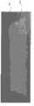
图8示出了检测到作为检测对象物的手指时的距离图像。区域104是表示手指的部分。在区域104中,得到了距离数据,表现为比作为背景的红外光反射部件26深的颜色。FIG. 8 shows a distance image when a finger as a detection target is detected.
CPU 42在检测区域内提取比规定浓度浓(即比规定的距离近)的像素。例如,提取比2m近的距离数据的像素。进而,CPU 42计算比规定浓度浓的像素块的像素数。关于比规定的像素数小的块(例如,面积比20像素小的块),不将其作为检测对象物而排除在外。CPU 42这样地判断检测对象物的有无。在判断为不存在检测对象物的情况下,返回步骤S1进行处理。The
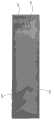
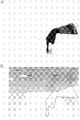
在判断为存在检测对象物的情况下,判断该检测对象物是否触摸到红外光反射部件26(步骤S4)。图8示出了作为检测对象物的手指未触摸红外光反射部件26时的距离图像,图9示出了手指触摸了红外光反射部件26时的距离图像。When it is determined that the detection target exists, it is determined whether or not the detection target has touched the infrared light reflecting member 26 (step S4). FIG. 8 shows a distance image when a finger as a detection target object does not touch the infrared
如图9所示,当手指接触了红外光反射部件26时,出现了反射图像106。这是因为,如图10所示,不仅检测到轨迹α那样由手指27直接反射时的红外光,还检测到轨迹β那样由红外反射部件26和手指27反射的红外光。CPU 42根据这样的反射图像106的有无,判断手指27是否接触到红外光反射部件26。As shown in FIG. 9, when a finger touches the infrared
由CPU 42执行的判断的详细情况如下。首先,提取检测对象物的外形。对于图8的图像,如图11A所示提取轮廓。对于图9的图像,如图11B所示提取轮廓。The details of the judgment performed by the
接着,CPU 42找出长度为检测对象物宽度的2倍以上的区域108。接着,判断是否存在与该区域108连续的突出部(以小的宽度进行连接、且宽度比该连接部大的部分)。如果存在,则将其识别为反射图像106。CPU 42计算反射图像106的面积,如果为规定值以上,则判断为检测对象物触摸了红外光反射部件26。Next, the
因此,在图8(图11A)中看不到反射图像106,因而CPU 42判断为作为检测对象物的手指未触摸红外光反射部件26。而在图9(图11B)中看到了反射图像106,因此CPU 42判断为作为检测对象物的手指触摸了红外光反射部件26。Therefore, in FIG. 8 ( FIG. 11A ), the
CPU 42在检测到检测对象物进行了触摸时,计算触摸位置(步骤S5)。在该实施方式中,如下所述地进行触摸位置的计算。When the
首先,根据不存在检测对象物的距离图像(参照图7),取得红外光反射部件26(即检测区域)的4个角的、图像上的坐标。该处理优选作为使用的前处理来进行。First, the coordinates on the image of the four corners of the infrared light reflecting member 26 (that is, the detection area) are obtained from the distance image (see FIG. 7 ) in which no detection target object exists. This treatment is preferably performed as a pretreatment for use.
在图11B中,取得手指的前端部122的距离图像上的坐标。接着,根据预先记录的红外光反射部件26的纵横大小,给定画面上的坐标与红外光反射部件26上的位置之间的对应关系,将所述前端部122的坐标转换为红外光反射部件26上的位置。In FIG. 11B , the coordinates on the distance image of the
例如,如图12A所示,设红外光反射部件26的4个角的图像上的坐标为(X1、Y1)(X2、Y2)(X3、Y3)(X4、Y4),图像上的触摸位置为(Xa、Ya)。将其变换为图12B所示的、红外光反射部件26上的坐标Xb、Yb(左上为0、0、右下为Ly、Lx的坐标)。此时,可使用图12的下部所示的变换式。按照以上方式来计算触摸位置。For example, as shown in FIG. 12A, suppose the coordinates on the image of the four corners of the infrared
接着,CPU 42根据工作模式进行与其对应的处理(步骤S6)。例如,如果是描绘模式,则根据检测对象物的移动来进行描绘。CPU 42反复进行这样的处理。Then, the
如上所述,在该实施方式中,无需使用特殊的笔和反射部件等,即可检测出检测对象物的位置而进行与其对应的处理。As described above, in this embodiment, the position of the detection object can be detected without using a special pen, reflection member, etc., and processing corresponding thereto can be performed.
1.4其他实施方式1.4 Other implementations
(1)在上述实施方式中,在检测区域的整个面上设置有红外光反射部件26。但是,如图13A所示,也可以在检测区域中呈格子状设置红外光反射部件26。当检测对象物进行了触摸时,如图13B所示,在距离图像中格子发生畸变。可以将这样的畸变位置检测为触摸位置。(1) In the above-described embodiment, the infrared
(2)在上述实施方式中,使用了深度照相机30作为深度传感器。一般而言,在深度照相机30中,大多还能够输出红外图像。但是,在该实施方式中,由于未使用红外图像,因此也可以使用不输出红外图像而输出深度的传感器。(2) In the above embodiments, the
2.第二实施方式2. Second Embodiment
2.1整体结构及硬件结构2.1 Overall structure and hardware structure
整体结构及硬件结构与第一实施方式相同。但是,在该实施方式中,与第一实施方式不同的方面是还使用了深度照相机的红外图像。The overall structure and hardware structure are the same as those of the first embodiment. However, this embodiment differs from the first embodiment in that an infrared image of a depth camera is also used.
2.2处理流程图2.2 Processing flow chart
图14、图15示出了控制程序56的处理流程图。步骤S1~S3与图6相同。另外,在该实施方式中,预先将不存在检测对象物的距离画面作为基准距离图像来保存,根据测量时的距离图像与基准距离图像的差分图像,判断检测对象物的有无。图16A示出了基准距离图像,图16B示出了测量时的距离图像。其差分图像如图17A所示。如果出现规定面积以上的块的差分图像,则判断为存在检测对象物。14 and 15 show flowcharts of processing of the
当判断为存在检测对象物时,CPU 42在距离图像中,提取检测对象物的外形(步骤S14)。图17B示出了所提取的外形。When it is determined that the detection target exists, the
接着,CPU 42从深度照相机30取入红外图像(步骤S15)。接着,CPU 42根据距离图像中的检测对象物的外形,提取红外图像中的检测对象物的外形(步骤S16)。在该实施方式中,无论是距离图像还是红外图像,都对相同范围进行摄像,像素数相同,因此,通过参照距离图像中的检测对象物的外形,能够容易地提取红外图像中的检测对象物的外形。Next, the
图18示出了这样提取的红外图像中的检测对象物的外形。比较图17B与图18的外形可知,两者基本一致。在检测对象物未触摸红外光反射部件26的情况下,如上所述两者的外形一致。因此,如果距离图像的外形与红外图像的外形的、检测对象物的前端部长度的差小于规定值,则CPU 42判断为检测对象物未触摸红外光反射部件26(步骤S17)。FIG. 18 shows the appearance of the object to be detected in the infrared image extracted in this way. Comparing the appearances of Fig. 17B and Fig. 18, it can be seen that the two are basically the same. When the object to be detected does not touch the infrared
另一方面,如图19A的距离图像、图19B的红外图像所示,在检测对象物触摸了红外光反射部件26的情况下,各个检测对象物的外形的前端长度不同。这是因为,当检测对象物触摸了红外光反射部件26时(或者极度接近时),检测对象物的影子(映入像)也作为图像被检测到。此时,红外图像的映入像较清晰且较大,距离图像的映入像则较小。因此,当检测对象物触摸了红外光反射部件26时,外形的前端长度变得不同。On the other hand, as shown in the distance image of FIG. 19A and the infrared image of FIG. 19B , when the detection objects touch the infrared
因此,如图20所示,在距离图像的外形的最下端(前端部)82与红外图像的外形的最下端(前端部)84的差Q超过了规定长度(换算成实际长度为5~10cm左右)的情况下,CPU 42判断为检测对象物触摸了红外光反射部件26(步骤S17)。Therefore, as shown in FIG. 20 , the difference Q between the lowermost end (tip portion) 82 of the profile of the distance image and the lowermost end (tip portion) 84 of the profile of the infrared image exceeds a prescribed length (converted to an actual length of 5 to 10 cm). left and right), the
接着,CPU 42进行触摸位置的计算(步骤S5)。该处理是通过计算距离图像的外形的最下端82的坐标来进行的。计算方法与第一实施方式相同。Next, the
当触摸位置的计算结束时,CPU 42与第一实施方式同样,进行基于触摸位置的处理(步骤S6)。When the calculation of the touch position is completed, the
2.3其他的实施方式2.3 Other Implementation Modes
(1)在上述各实施方式中,在检测区域中设置了红外光反射部件26。但是,作为代替,也可以使用红外光吸收部件。(1) In each of the above-described embodiments, the infrared
(2)在上述各实施方式中,将检测单元24配置在与投影仪14不同的位置。但是,也可以在投影仪14上设置深度照相机24。或者,可以使检测单元24与投影仪14一体化。(2) In each of the above-described embodiments, the detection unit 24 is arranged at a different position from the
(3)在上述各实施方式中,使用了红外光和红外光反射部件26。但是,作为代替,也可以使用超声波和超声波反射部件(吸收部件)、紫外光和紫外光反射部件(吸收部件)、电磁波和电磁波反射部件(吸收部件)等。(3) In each of the above-described embodiments, infrared light and the infrared
(4)在上述各实施方式中,作为影像显示部,使用了投影仪。但是,也可以使用显示器。此时,无需使用透明电极等即可实现触摸面板。(4) In each of the above-mentioned embodiments, a projector is used as the video display unit. However, a monitor can also be used. At this time, a touch panel can be realized without using transparent electrodes or the like.
(5)在上述各实施方式中,以手指为例对检测对象物进行了说明。但是,通常的书写工具、指点杆等用于反射红外光的物件都可以作为检测对象物来使用。(5) In each of the above-mentioned embodiments, the finger is taken as an example to describe the object to be detected. However, common writing implements, pointing sticks and other objects for reflecting infrared light can be used as detection objects.
(6)上述各实施方式中的装置也可以作为预先完成的装置来构建,也可以通过携带深度照相机和红外光反射部件,并将红外光反射部件26置于桌子或墙壁等上而构建为装置。(6) The devices in the above-mentioned embodiments can also be constructed as a pre-finished device, and can also be constructed as a device by carrying a depth camera and an infrared light reflecting part, and placing the infrared
(7)在上述各实施方式中,检测出检测对象物触摸了红外光反射部件26的情况而进行处理。但是,也可以是,只要检测到检测对象物,则无论有无进行触摸都进行处理。(7) In each of the above-described embodiments, it is detected that the object to be detected has touched the infrared
(8)另外,在上述实施方式中,使用了像通常那样对红外光进行反射的红外光反射部件。但是,也可以如图21所示,使用在具有向入射方向反射红外光的构造的红外光反射部300上重叠以一定程度反射红外光的透明膜310所得的部件,作为红外光反射部件26。由于红外光反射部300向入射方向反射红外光,因此从红外光照射器28射出的红外光回到原来的红外光反射器28。因此,在不存在检测对象物的状态中,位于与红外光照射器28分离的位置处的深度照相机30检测不到红外光,不能进行距离测量。如果存在检测对象物,则能够检测到被其反射的红外光而得到距离测量数据。(8) In addition, in the above-mentioned embodiment, the infrared light reflecting member which normally reflects infrared light is used. However, as shown in FIG. 21 , as the infrared
Claims (13)
Translated fromChineseApplications Claiming Priority (3)
| Application Number | Priority Date | Filing Date | Title |
|---|---|---|---|
| JP2012077675AJP2013206373A (en) | 2012-03-29 | 2012-03-29 | Interactive display device |
| JP2012-077675 | 2012-03-29 | ||
| PCT/JP2012/005443WO2013145035A1 (en) | 2012-03-29 | 2012-08-29 | Interactive display device |
Publications (1)
| Publication Number | Publication Date |
|---|---|
| CN103492982Atrue CN103492982A (en) | 2014-01-01 |
Family
ID=47045108
Family Applications (1)
| Application Number | Title | Priority Date | Filing Date |
|---|---|---|---|
| CN201280000880.1APendingCN103492982A (en) | 2012-03-29 | 2012-08-29 | Interactive display device |
Country Status (3)
| Country | Link |
|---|---|
| JP (1) | JP2013206373A (en) |
| CN (1) | CN103492982A (en) |
| WO (1) | WO2013145035A1 (en) |
Cited By (2)
| Publication number | Priority date | Publication date | Assignee | Title |
|---|---|---|---|---|
| CN109219426A (en)* | 2016-06-08 | 2019-01-15 | 八乐梦医用床有限公司 | Rehabilitation training sub-controlling unit and computer program |
| CN111258410A (en)* | 2020-05-06 | 2020-06-09 | 北京深光科技有限公司 | Man-machine interaction equipment |
Families Citing this family (2)
| Publication number | Priority date | Publication date | Assignee | Title |
|---|---|---|---|---|
| JP2015158558A (en)* | 2014-02-24 | 2015-09-03 | セイコーエプソン株式会社 | projector |
| JP2016099742A (en)* | 2014-11-19 | 2016-05-30 | 株式会社東芝 | Information processing apparatus, video projection apparatus, information processing method, and program |
Citations (5)
| Publication number | Priority date | Publication date | Assignee | Title |
|---|---|---|---|---|
| EP1168233A2 (en)* | 2000-06-28 | 2002-01-02 | Nokia Mobile Phones Ltd. | Method and arrangement for entering data in an electronic apparatus and an electronic apparatus |
| US20060291049A1 (en)* | 2005-06-24 | 2006-12-28 | Hewlett-Packard Development Company L.P. | Screen |
| CN101595418A (en)* | 2007-01-26 | 2009-12-02 | 微软公司 | Alternating light sources is to reduce direct reflection |
| CN102053763A (en)* | 2009-10-26 | 2011-05-11 | 精工爱普生株式会社 | Optical position detection device and display device with position detection function |
| CN102369498A (en)* | 2009-02-11 | 2012-03-07 | 智能技术无限责任公司 | Touch Indicator Disambiguation via Active Display Feedback |
Family Cites Families (5)
| Publication number | Priority date | Publication date | Assignee | Title |
|---|---|---|---|---|
| JPH05127809A (en)* | 1991-04-19 | 1993-05-25 | Sharp Corp | Three-dimensional spatial coordinate input device |
| JP5053188B2 (en)* | 2008-06-18 | 2012-10-17 | 株式会社リコー | Input device and image forming apparatus |
| WO2011011009A1 (en)* | 2009-07-23 | 2011-01-27 | Hewlett-Packard Development Company, L.P. | Display with an optical sensor |
| JP5276577B2 (en) | 2009-12-21 | 2013-08-28 | 株式会社日立ソリューションズ | Front projection type electronic blackboard system and calibration start method |
| JP5530809B2 (en) | 2010-06-01 | 2014-06-25 | 株式会社日立ソリューションズ | Position detection apparatus and image processing system |
- 2012
- 2012-03-29JPJP2012077675Apatent/JP2013206373A/enactivePending
- 2012-08-29WOPCT/JP2012/005443patent/WO2013145035A1/enactiveApplication Filing
- 2012-08-29CNCN201280000880.1Apatent/CN103492982A/enactivePending
Patent Citations (5)
| Publication number | Priority date | Publication date | Assignee | Title |
|---|---|---|---|---|
| EP1168233A2 (en)* | 2000-06-28 | 2002-01-02 | Nokia Mobile Phones Ltd. | Method and arrangement for entering data in an electronic apparatus and an electronic apparatus |
| US20060291049A1 (en)* | 2005-06-24 | 2006-12-28 | Hewlett-Packard Development Company L.P. | Screen |
| CN101595418A (en)* | 2007-01-26 | 2009-12-02 | 微软公司 | Alternating light sources is to reduce direct reflection |
| CN102369498A (en)* | 2009-02-11 | 2012-03-07 | 智能技术无限责任公司 | Touch Indicator Disambiguation via Active Display Feedback |
| CN102053763A (en)* | 2009-10-26 | 2011-05-11 | 精工爱普生株式会社 | Optical position detection device and display device with position detection function |
Cited By (3)
| Publication number | Priority date | Publication date | Assignee | Title |
|---|---|---|---|---|
| CN109219426A (en)* | 2016-06-08 | 2019-01-15 | 八乐梦医用床有限公司 | Rehabilitation training sub-controlling unit and computer program |
| CN111258410A (en)* | 2020-05-06 | 2020-06-09 | 北京深光科技有限公司 | Man-machine interaction equipment |
| CN111258410B (en)* | 2020-05-06 | 2020-08-04 | 北京深光科技有限公司 | A human-computer interaction device |
Also Published As
| Publication number | Publication date |
|---|---|
| JP2013206373A (en) | 2013-10-07 |
| WO2013145035A1 (en) | 2013-10-03 |
Similar Documents
| Publication | Publication Date | Title |
|---|---|---|
| CN102799318B (en) | A kind of man-machine interaction method based on binocular stereo vision and system | |
| KR102335132B1 (en) | Multi-modal gesture based interactive system and method using one single sensing system | |
| US9454260B2 (en) | System and method for enabling multi-display input | |
| JP3968477B2 (en) | Information input device and information input method | |
| US8491135B2 (en) | Interactive projection with gesture recognition | |
| KR101102953B1 (en) | Multi-touch based large interactive display system and method | |
| US8963883B2 (en) | Touchless interactive display system | |
| US20110205155A1 (en) | Methods and Systems for Position Detection Using an Interactive Volume | |
| KR100974894B1 (en) | 3d space touch apparatus using multi-infrared camera | |
| WO2012124730A1 (en) | Detection device, input device, projector, and electronic apparatus | |
| US20130257811A1 (en) | Interactive display device | |
| CN102541365A (en) | System and method for generating multi-touch commands | |
| CN104298405B (en) | Touch module, projection system and touch method thereof | |
| TW201423484A (en) | Motion detection system | |
| TWI484386B (en) | Display with an optical sensor | |
| CN103492982A (en) | Interactive display device | |
| CN104850272B (en) | Optical image type touch system and touch image processing method | |
| CN103135764B (en) | Movement detection device | |
| KR101071864B1 (en) | Touch and Touch Gesture Recognition System | |
| KR20090116544A (en) | Infrared camera space touch sensing device, method and screen device | |
| US9019243B2 (en) | Optical coordinate input device | |
| JP4687820B2 (en) | Information input device and information input method | |
| KR101002071B1 (en) | Multi-infrared camera projection image touch device | |
| JP2007200353A (en) | Information processor and information processing method | |
| TWI573043B (en) | The virtual two - dimensional positioning module of the input device |
Legal Events
| Date | Code | Title | Description |
|---|---|---|---|
| C06 | Publication | ||
| PB01 | Publication | ||
| C10 | Entry into substantive examination | ||
| SE01 | Entry into force of request for substantive examination | ||
| C02 | Deemed withdrawal of patent application after publication (patent law 2001) | ||
| WD01 | Invention patent application deemed withdrawn after publication | Application publication date:20140101 |