CN103492008A - Flushing medical devices - Google Patents
Flushing medical devicesDownload PDFInfo
- Publication number
- CN103492008A CN103492008ACN201280010296.4ACN201280010296ACN103492008ACN 103492008 ACN103492008 ACN 103492008ACN 201280010296 ACN201280010296 ACN 201280010296ACN 103492008 ACN103492008 ACN 103492008A
- Authority
- CN
- China
- Prior art keywords
- instruments
- medical apparatus
- sidewall
- flushing
- cut portion
- Prior art date
- Legal status (The legal status is an assumption and is not a legal conclusion. Google has not performed a legal analysis and makes no representation as to the accuracy of the status listed.)
- Granted
Links
Images


Classifications
- A—HUMAN NECESSITIES
- A61—MEDICAL OR VETERINARY SCIENCE; HYGIENE
- A61M—DEVICES FOR INTRODUCING MEDIA INTO, OR ONTO, THE BODY; DEVICES FOR TRANSDUCING BODY MEDIA OR FOR TAKING MEDIA FROM THE BODY; DEVICES FOR PRODUCING OR ENDING SLEEP OR STUPOR
- A61M5/00—Devices for bringing media into the body in a subcutaneous, intra-vascular or intramuscular way; Accessories therefor, e.g. filling or cleaning devices, arm-rests
- A61M5/178—Syringes
- A61M5/31—Details
- A61M5/3129—Syringe barrels
- A61M5/3134—Syringe barrels characterised by constructional features of the distal end, i.e. end closest to the tip of the needle cannula
- A—HUMAN NECESSITIES
- A61—MEDICAL OR VETERINARY SCIENCE; HYGIENE
- A61M—DEVICES FOR INTRODUCING MEDIA INTO, OR ONTO, THE BODY; DEVICES FOR TRANSDUCING BODY MEDIA OR FOR TAKING MEDIA FROM THE BODY; DEVICES FOR PRODUCING OR ENDING SLEEP OR STUPOR
- A61M39/00—Tubes, tube connectors, tube couplings, valves, access sites or the like, specially adapted for medical use
- A61M39/10—Tube connectors; Tube couplings
- A61M2039/1033—Swivel nut connectors, e.g. threaded connectors, bayonet-connectors
- A—HUMAN NECESSITIES
- A61—MEDICAL OR VETERINARY SCIENCE; HYGIENE
- A61M—DEVICES FOR INTRODUCING MEDIA INTO, OR ONTO, THE BODY; DEVICES FOR TRANSDUCING BODY MEDIA OR FOR TAKING MEDIA FROM THE BODY; DEVICES FOR PRODUCING OR ENDING SLEEP OR STUPOR
- A61M39/00—Tubes, tube connectors, tube couplings, valves, access sites or the like, specially adapted for medical use
- A61M39/10—Tube connectors; Tube couplings
- A61M2039/1077—Adapters, e.g. couplings adapting a connector to one or several other connectors
- A—HUMAN NECESSITIES
- A61—MEDICAL OR VETERINARY SCIENCE; HYGIENE
- A61M—DEVICES FOR INTRODUCING MEDIA INTO, OR ONTO, THE BODY; DEVICES FOR TRANSDUCING BODY MEDIA OR FOR TAKING MEDIA FROM THE BODY; DEVICES FOR PRODUCING OR ENDING SLEEP OR STUPOR
- A61M2206/00—Characteristics of a physical parameter; associated device therefor
- A61M2206/10—Flow characteristics
- A—HUMAN NECESSITIES
- A61—MEDICAL OR VETERINARY SCIENCE; HYGIENE
- A61M—DEVICES FOR INTRODUCING MEDIA INTO, OR ONTO, THE BODY; DEVICES FOR TRANSDUCING BODY MEDIA OR FOR TAKING MEDIA FROM THE BODY; DEVICES FOR PRODUCING OR ENDING SLEEP OR STUPOR
- A61M5/00—Devices for bringing media into the body in a subcutaneous, intra-vascular or intramuscular way; Accessories therefor, e.g. filling or cleaning devices, arm-rests
- A61M5/178—Syringes
- A61M5/31—Details
- A61M5/32—Needles; Details of needles pertaining to their connection with syringe or hub; Accessories for bringing the needle into, or holding the needle on, the body; Devices for protection of needles
- A61M5/34—Constructions for connecting the needle, e.g. to syringe nozzle or needle hub
- A61M5/347—Constructions for connecting the needle, e.g. to syringe nozzle or needle hub rotatable, e.g. bayonet or screw
Landscapes
- Health & Medical Sciences (AREA)
- Vascular Medicine (AREA)
- Engineering & Computer Science (AREA)
- Anesthesiology (AREA)
- Biomedical Technology (AREA)
- Heart & Thoracic Surgery (AREA)
- Hematology (AREA)
- Life Sciences & Earth Sciences (AREA)
- Animal Behavior & Ethology (AREA)
- General Health & Medical Sciences (AREA)
- Public Health (AREA)
- Veterinary Medicine (AREA)
- Infusion, Injection, And Reservoir Apparatuses (AREA)
Abstract
Description
Translated fromChinese技术领域technical field
本文一般地讨论了用于抽出、注射或滴注流体的注射器及冲洗医疗器械。更具体地讨论了用于冲洗血管进入器械的带多个流动通道的注射器顶部和冲洗顶部适配器。This article generally discusses syringe and flush medical devices used to withdraw, inject, or instill fluids. A syringe tip with multiple flow channels and a flush tip adapter for flush vascular access devices are discussed in more detail.
背景技术Background technique
现有技术的注射器通常具有带注射器顶部和柱塞的筒体。通常形成穿过注射器顶部的单个内腔。当流体从注射器顶部被排出时,该单个内腔形成可预知的密闭或密封型式的单一流。Prior art syringes typically have a barrel with a syringe tip and plunger. Typically a single lumen is formed through the top of the syringe. This single lumen forms a single stream in a predictable hermetic or sealed pattern as fluid is expelled from the top of the syringe.
注射器顶部通常是用某种行业内的宽标准圆锥接头或者鲁尔圆锥接头(Luer taper)制成。该圆锥接头允许使用由不同生产商制造的不同注射器顶部,以便与具有配对的阴型鲁尔圆锥接头的医疗器械相匹配或配合。Syringe tips are usually made with some kind of industry wide standard taper or Luer taper. The cone allows the use of different syringe tips made by different manufacturers to match or mate with medical devices having mating female luer cones.
发明内容Contents of the invention
本发明冲洗医疗器械及相关方法的各种实施例具有若干特征,这些特征中并非仅单一特征导致它们可取的特性。现在将在不限制由所附权利要求所表示本发明实施例的范围的情况下,对它们的更显著特征进行简单描述。在考虑此描述之后,特别是在阅读标题为“具体实施方式”一节之后,将会理解本发明实施例的特征是如何提供各优点,该特征包括提供用于冲洗血管进入器械的宽流动型式的能力。The various embodiments of the present flushing medical devices and associated methods share several features, no single one of which is responsible for their desirable properties. Without limiting the scope of the embodiments of the invention represented by the appended claims, their more salient features will now be briefly described. After considering this description, and particularly after reading the section entitled "Detailed Description of the Preferred Embodiments," one will understand how the features of embodiments of the invention provide advantages, including providing a broad flow pattern for flushing a vascular access device. Ability.
提供了一种冲洗医疗器械,其包括用于冲洗血管进入器械(例如无针进入端口阀、导管和阳型鲁尔连接器)的顶部。在一个实例中,提供一种具有主体的顶部(tip),该主体包括顶端(tip end),顶端大体垂直于具有鲁尔圆锥接头的侧壁,并且其中,顶端和侧壁限定在这两者之间的交汇部。在一个实例中,侧壁的表面积大于顶端上的表面积。所述器械还包括由侧壁所形成的内腔,并且其中,两个或更多个间隔开的切除部(cut-out)被形成为穿过侧壁并且穿过交汇部的至少一部分。在另一个实例中,仅形成穿过侧壁且穿过交汇部的至少一部分的一个切除部。An irrigation medical device is provided that includes a top for irrigation of a vascular access device such as a needle-free access port valve, a catheter, and a male luer connector. In one example, there is provided a tip having a body including a tip end generally perpendicular to a side wall having a luer, and wherein the tip and the side wall are defined between the two intersection between. In one example, the sidewall has a greater surface area than the surface area on the tip. The instrument also includes a lumen formed by the sidewall, and wherein two or more spaced apart cut-outs are formed through the sidewall and through at least a portion of the junction. In another example, only one cutout is formed through the sidewall and through at least a portion of the junction.
根据本发明的器械,还提供一种定位成与顶端相对的接收端,该接收端具有带阴型鲁尔圆锥接头的内壁表面。According to the device of the present invention, there is also provided a receiving end positioned opposite the tip, the receiving end having an inner wall surface with a female Luer cone.
所述冲洗医疗器械还可以包括锥形的裙部以及凸缘,限定在凸缘和裙部之间以及在主体上的缺口。颈套可位于该缺口处。该颈套可以相对于主体旋转。然而,所述冲洗医疗器械也可以实施为不具有颈套。The irrigation medical device may also include a tapered skirt and a flange defining a gap between the flange and the skirt and in the body. A collar can be located at the notch. The collar is rotatable relative to the main body. However, the irrigation medical device can also be embodied without a collar.
带冲洗顶部的冲洗医疗器械可以是注射器的一部分并且附接到注射器筒体并且具有柱塞,该柱塞具有可滑动地设置在其中的推动凸缘。注射器筒体可以具有不同的容积大小。A flush medical device with a flush top may be part of a syringe and attached to the syringe barrel and have a plunger with a pusher flange slidably disposed therein. Syringe barrels are available in different volume sizes.
为了覆盖顶部(例如在包装和/或运输期间),可以将帽罩安装在顶部上。该帽罩也可以与螺纹颈套螺纹接合。In order to cover the top (eg during packaging and/or shipping), a hood may be mounted on the top. The cap can also be threadedly engaged with the threaded collar.
所述冲洗医疗器械还可以包括形成于顶端的表面区域上的切除部。这些切除部可以具有各种形状,例如梯形形状、大体矩形的形状、正方形形状、螺旋形形状和倾斜形状。The irrigation medical device may also include a cutout formed on the surface area of the tip. These cutouts may have various shapes such as a trapezoidal shape, a generally rectangular shape, a square shape, a spiral shape, and an oblique shape.
所述冲洗医疗器械可以任选地包括周边,该周边限定仅形成于顶端表面区域上的开口。该开口可以用作另外的流动端口或通道,或者用于容纳无针进入端口阀的尖顶。The irrigation medical device may optionally include a perimeter defining an opening formed only on the tip surface area. This opening can be used as an additional flow port or channel, or to accommodate the tip of a needle-free access port valve.
另一个冲洗医疗器械的实例包括具有主体的顶部,该主体包括顶端,顶端大体垂直于具有鲁尔圆锥接头的侧壁,其中,顶端和侧壁限定在这两者之间的交汇部,并且其中,侧壁的表面积大于顶端上的表面积。内腔由侧壁形成,并且具有阴型鲁尔圆锥接头的接收端设置在与顶端相对的端部处。螺纹颈套可以位于主体的外部,并且其中,两个或更多个间隔开的切除部被形成为穿过侧壁并且穿过交汇部的至少一部分。在另一个实例中,仅形成穿过侧壁的单个流动通道。Another example of an irrigated medical device includes a top having a body including a tip generally perpendicular to a side wall having a luer, wherein the tip and the side wall define a junction therebetween, and wherein , the sidewalls have a larger surface area than the top. The lumen is formed by the side walls, and a receiving end with a female luer is provided at the end opposite the tip. The threaded collar may be located on the exterior of the body, and wherein two or more spaced apart cutouts are formed through the sidewall and through at least a portion of the junction. In another example, only a single flow channel is formed through the sidewall.
又一个冲洗医疗器械的实例包括具有主体的顶端,该主体包括顶端,顶端大体垂直于具有鲁尔圆锥接头的侧壁,其中,顶端和侧壁限定在这两者之间的交汇部,并且其中,侧壁的表面积大于顶端上的表面积。内腔由侧壁形成,并且筒体附接到顶部。柱塞可滑动地设置在筒体内,并且其中,两个或更多个间隔开的切除部被形成为穿过侧壁并且穿过交汇部的至少一部分。Yet another example of an irrigated medical device includes a tip having a body including a tip generally perpendicular to a sidewall having a luer, wherein the tip and the sidewall define a junction therebetween, and wherein , the sidewalls have a larger surface area than the top. The inner cavity is formed by the side walls, and the barrel is attached to the top. The plunger is slidably disposed within the barrel, and wherein two or more spaced apart cutouts are formed through the sidewall and through at least a portion of the intersection.
本申请还包括一种用于冲洗血管进入器械的方法。该方法包括:将柱塞压入注射器筒体或者借助于自动输注装置进行泵送;将单个流动流排放到冲洗医疗器械中;以及将多个流从位于冲洗医疗器械顶部处的多个流动通道中排放出来。在另一个实例中,流动流被从单一流动通道中排放出来,并且其中,该单一流动通道形成为穿过顶部侧壁的切除部。The present application also includes a method for flushing a vascular access device. The method includes: depressing a plunger into a syringe barrel or pumping with the aid of an automatic infusion device; discharging a single flow stream into an irrigated medical device; discharged from the channel. In another example, the flow stream is discharged from a single flow channel, and wherein the single flow channel is formed as a cutout through the top sidewall.
附图说明Description of drawings
现在将详细地描述本发明装置、系统及相关方法的各种实施例,重点是强调有利的特征。这些实施例描述了附图中所示的新型且非显而易见的装置,附图只是为了说明的目的。这些附图包括以下图示,其中相同的附图标记表示相同的部件:Various embodiments of the inventive devices, systems, and associated methods will now be described in detail, with emphasis on emphasizing advantageous features. These embodiments describe novel and non-obvious devices shown in the drawings, which are for illustration purposes only. These drawings include the following illustrations, in which like reference numerals refer to like parts:
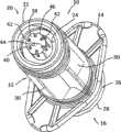
图1示出了具有带多个流动通道的注射器顶部的注射器的透视图;Figure 1 shows a perspective view of a syringe with a syringe top with multiple flow channels;
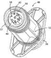
图2是图1的注射器的侧剖面局部透视图;Figure 2 is a partial perspective view in side section of the syringe of Figure 1;
图3是替代的注射器的透视图,该注射器具有注射器顶部,注射器顶部具有多个流动通道和中心流动端口;Figure 3 is a perspective view of an alternative syringe having a syringe top with multiple flow channels and a central flow port;
图3A是根据一个替代实例提供的注射器顶部的正视图;Figure 3A is a front view of the top of a syringe provided according to an alternative example;
图4示出了根据本发明器械、系统和方法的一些方面提供的冲洗顶部适配器的透视图;Figure 4 illustrates a perspective view of a flush top adapter provided in accordance with aspects of the devices, systems and methods of the present invention;
图5是图4的冲洗顶部适配器的侧剖面局部透视图;5 is a partial perspective view in side section of the flush top adapter of FIG. 4;
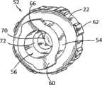
图6是从后面角度观察到的图4的冲洗顶部适配器的透视图;Figure 6 is a perspective view of the flush top adapter of Figure 4 viewed from the rear;
图7是从另一个角度观察到的图4的冲洗顶部适配器的透视图;Figure 7 is a perspective view of the flush top adapter of Figure 4 viewed from another angle;
图8是替代的冲洗顶部适配器的透视图,该冲洗顶部适配器具有多个流动通道和中心流动端口;Figure 8 is a perspective view of an alternative flush top adapter having multiple flow channels and a central flow port;
图9是图8的冲洗顶部适配器的侧剖面局部透视图;9 is a partial perspective view in side section of the flush top adapter of FIG. 8;
图10是具有多个流动通道的另一替代冲洗顶部适配器的透视图;Figure 10 is a perspective view of another alternative flush top adapter having multiple flow channels;
图11是具有多个流动通道的又一替代冲洗顶部适配器的透视图;Figure 11 is a perspective view of yet another alternative flush top adapter having multiple flow channels;
图12是具有多个流动通道的再一替代冲洗顶部适配器的透视图;Figure 12 is a perspective view of yet another alternative flush top adapter having multiple flow channels;
图13是具有多个流动通道的又一替代冲洗顶部适配器的透视图;Figure 13 is a perspective view of yet another alternative flush top adapter having multiple flow channels;
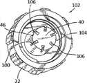
图14是具有多个流动通道的又一替代冲洗顶部适配器的透视图;Figure 14 is a perspective view of yet another alternative flush top adapter having multiple flow channels;
图15是根据本发明器械、系统及方法的一些方面提供的替代的冲洗顶部适配器的剖面侧视图,其具有可旋转螺纹颈套;15 is a cutaway side view of an alternative flush top adapter having a rotatable threaded collar provided in accordance with aspects of the devices, systems, and methods of the present invention;
图16是图15的冲洗顶部适配器的侧视图,未示出可旋转螺纹颈套;Figure 16 is a side view of the flush top adapter of Figure 15, without the rotatable threaded collar;
图17是帽罩的剖面侧视图;Figure 17 is a sectional side view of the cap;
图18是包括阀和阀致动器的导管的剖面侧视图,冲洗顶部适配器被接合在近端,用于打开阀并且冲洗导管;并且18 is a cross-sectional side view of a catheter including a valve and valve actuator with an irrigation tip adapter engaged at the proximal end for opening the valve and flushing the catheter; and
图19是示意性流程图,示出了根据本发明方法的方面的冲洗医疗器械的使用方法。Figure 19 is a schematic flow diagram illustrating a method of use for flushing a medical instrument according to aspects of the method of the present invention.
具体实施方式Detailed ways
下面陈述的详细说明连同附图意图是对根据本发明器械、系统和方法的各方面的冲洗医疗器械(例如注射器和冲洗顶部适配器)的本发明优选实施例进行描述,并非意图代表可构成或应用本发明器械、系统和方法的仅有形态。该描述连同图示说明的实施例陈述了构成和使用本发明器械、系统和方法的冲洗医疗器械的特征和步骤,然而应该理解的是相同或同等的功能和结构可由不同的实施例来实施,这些不同的实施例也意图包含在本发明器械、系统和方法的精神和范围内。如本文中的其它部分所示,相同的元件数字意图是表示相同或类似的元件。The detailed description set forth below, together with the accompanying drawings, is intended to describe preferred embodiments of the invention for irrigated medical devices (eg, syringes and irrigated tip adapters) according to aspects of the devices, systems, and methods of the invention, and is not intended to represent Exclusive form of the devices, systems and methods of the invention. This description, together with the illustrated embodiments, sets forth the features and steps of flushing medical devices that make up and use the devices, systems, and methods of the present invention, however, it should be understood that the same or equivalent functions and structures may be performed by different embodiments, These various embodiments are also intended to be within the spirit and scope of the devices, systems and methods of the present invention. As indicated elsewhere herein, like element numbers are intended to refer to the same or similar elements.
如本文中所述,在通常的使用中,词语“近侧的”意图是指当正常使用时与患者相比更靠近使用者的器械的一端。词语“远侧的”意图是指与使用者相比更靠近患者的器械的一端。除非上下文另有说明,词语“近侧的”和“远侧的”不需要是最近端的点或者最远端的点,尽管这种端点也落在各自词语的范围内。As used herein, the word "proximal", in common usage, is intended to refer to the end of the instrument that is closer to the user than the patient when in normal use. The word "distal" is intended to refer to the end of the instrument that is closer to the patient than the user. Unless the context dictates otherwise, the words "proximal" and "distal" need not be the proximal-most point or the most-distal point, although such endpoints also fall within the scope of the respective words.
图1示出了根据本发明器械、系统和方法的一些方面提供的注射器10的透视图。在一个实施例中,注射器10包括筒体12,该筒体12具有位于近端16的抓持凸缘14和位于远端20的注射器顶部18,该注射器顶部18优选地是用于与阴型鲁尔接头配对接合的鲁尔顶部,例如导管毂、无针端口进入阀、阳型鲁尔连接器等。示例性的无针端口进入阀公开于美国专利第5,439,451和第5,700,248号中,这些专利的内容以参考的方式明确地并入本文中用于所有目的。示例性的阳型鲁尔连接器公开于美国专利第6,964,406号和第7,803,140号,这些专利的内容以参考的方式明确地并入本文中用于所有目的。示例性的导管组件公开于美国专利第7,736,339、7,374,554、7,625,360、5,879,337和6,629,959号以及2010年2月11日提交的专利公开WO 2010/093792 Al;这些专利文件的内容以参考的方式明确地并入本文中用于所有目的。Figure 1 shows a perspective view of a
如图所示,注射器10包括带内螺纹24的颈套22,以用作鲁尔锁。然而,注射器10也可以实施为不具有螺纹颈套,以用作鲁尔滑动件。活塞或柱塞26具有柱塞顶部34(图2)并且推动凸缘28可滑动地位于注射器筒体内,用于从筒体中抽出或排出流体。在一个实例中,柱塞26由多个纵向肋条30和径向肋条32制成(图2)。在另一个实例中,柱塞由具有一个或多个肋条的中央芯或杆制成且不具有柱塞顶部。换句话说,柱塞杆和柱塞顶部形成为整体并且在本行业中通常被称为二件式注射器。图2的注射器在本行业中通常被称为三件式注射器。As shown, the
注射器10可利用已知方法用一些已知的现有技术的塑料材料制成。注射器10优选地由透明或半透明材料制成,以允许透过注射器筒体观察。较不优选地,注射器筒体由不透明材料制成。可将刻度标记、刻度、标志和/或其它标记(例如批号)印在注射器筒体的外侧,用于参考的目的。
除了图1外还参照图2,注射器顶部18包括细长主体36,该细长主体36包括连接到注射器筒体远端的基部38和具有大体平坦端面的顶端40,其可以实施为具有弧形或锥形。在图示的实例中,顶端40的中心部44是实心的并且不包括内腔。相反,中心部44包括多个径向的流动通道42。在一个实例中,各流动通道42的形状通常为矩形或者直线形,并且至少包括形成于顶端40上或者穿过顶端40而形成的切除部。更优选地,各流动通道42由切除部形成,该切除部被形成为穿过顶端40和顶部主体36二者,位于其交汇部。尽管示出了六个流动通道42,但也可包括少于或多于六个流动通道。Referring to FIG. 2 in addition to FIG. 1 , the
在一个具体实例中,各流动通道42形成在顶端40和顶部主体36的交汇部46处或者穿过交汇部46,使得当经过注射器顶部排出流体时,流体轴向地、径向地、同时轴向地和径向地、和/或任意地流动。然而,可通过设置仅穿过顶端而不穿过顶部主体的切除部而形成各流动通道42,使得当经过注射器顶部排出流体时,流体仅轴向地流经多个轴向切除部。在顶端40可包括一个或多个突起或突出物(未图示),用于仅轴向流动的实施例,以避免密封或阻塞流动通道42,例如当顶端邻接有可能密封仅轴向流动通道的平表面时。如下面进一步的论述,与具有单个中心内腔的现有技术注射器的流动型式相比,经本发明注射器的顶部排出的流体具有大体上大的流动型式。In one particular example, each
现在参照图3,示出了替代的注射器48的透视图,该注射器48具有带多个流动通道42的注射器顶部18和大体位于中心的端口50。位于中心的端口50可具有圆形形状并且其直径可相对于径向布置的流动通道42而变化。例如,如果意图使更多的流体流流动经过径向布置的流动通道42,那么中心端口50可具有与意图使较少流体流流动经过径向布置流动通道42时相比相对较小的直径。在其它实施例中,位于中心的流动端口50具有非圆形的形状或构造(例如矩形、椭圆形、三角形、不规则形状等),并且可以偏心地位于顶端40上。此外,在顶端可包括一个或多个突起,以防止将中心端口50和流动通道42抵靠大体平坦表面密封。Referring now to FIG. 3 , a perspective view of an
在又一个实施例中,中心端口50的尺寸被设计成容纳位于无针进入端口阀的密封件内的尖顶,例如美国专利第5,700,248号中所示出的。当被插入'248专利的无针进入端口阀的鲁尔进口时,注射器的顶部18向下推动到无针进入端口阀的密封件上以打开该密封件,同时中心端口50包围尖顶以便容纳该尖顶。然后,从注射器中排放出来的流体流将会以大于典型注射器的流动型式而流经各径向布置的流动通道42,从而冲洗无针进入端口装置的内表面。In yet another embodiment, the
可以通过将注射器顶部插入血管进入器械(例如插入导管毂或无针进入端口阀的阴型鲁尔连接器),来使用图1-3的注射器,并且如果该注射器具有螺纹颈套,则使注射器筒体旋转以使该颈套与血管进入器械上的螺纹接合。然后推动注射器上的柱塞,以将流体从注射器顶部排出。因为与现有技术注射器顶部上的单个内腔相比本发明注射器的顶部具有多个通道,所以使流体径向地、轴向地、和/或任意地经过血管进入器械排出,以冲洗血管进入器械的内室的大多数的(如果不是所有的)缝隙。所公开的注射器的流动通道也可包括与图示所不同的形状或构造,如下面关于各种冲洗顶部适配器进一步描述的。The syringes of Figures 1-3 can be used by inserting the top of the syringe into a vascular access device, such as a female luer connector into a catheter hub or needleless access port valve, and if the syringe has a threaded collar, make the syringe The barrel is rotated to engage the collar with the threads on the vascular access device. Then push the plunger on the syringe to expel the fluid from the top of the syringe. Because the top of the syringe of the present invention has multiple channels compared to the single lumen on the top of prior art syringes, fluid is expelled radially, axially, and/or optionally through the vascular access device to flush the vascular access device. Most, if not all, of the internal chambers of a device. The flow channels of the disclosed syringes may also include shapes or configurations other than those shown, as further described below with respect to the various flush tip adapters.
图3A是根据本发明器械的一些方面提供的替代的注射器顶部18的正视图。该注射器顶部包括具有厚度的顶部主体36以及被一对肋条或桥200连接到顶部主体36的顶端40。顶端40和桥200在顶部的端部限定或形成两个开口通道202。经过顶部18排出的流体被构造成流动经过两个通道202以产生流动型式(flow pattern)。为了增加两个开口通道202的表面积,可以在顶部主体3的内表面206上形成一个或多个任选的底切204。因此,与现有技术注射器的可比较的单个内腔相比,本实施例的注射器顶部18可以提供更大的流动轮廓或型式。Figure 3A is a front view of an
图4示出了根据本发明器械、系统和方法的一些方面提供的冲洗顶部适配器52的透视图。如图所示,冲洗顶部适配器52包括具有接收端56的主体54、近端16、位于远端20的顶部58、以及具有位于顶端和接收端之间的内螺纹的螺纹颈套22。顶端优选地形成为具有用于接合阴型鲁尔接头的鲁尔圆锥接头。在螺纹颈套22的外表面可包括多个间隔开的突出物62,以有助于抓持冲洗顶部适配器。优选地,突出物沿外表面相等地间隔。替代地,包括了滚圆的或半球形的突出物(例如凸瘤)而不是细长突出物。凸瘤可任意地形成于外表面上或者形成为阵列。如图所示,在近端16处包括外螺纹60从而提供阴型鲁尔锁,如下面进一步的论述。FIG. 4 illustrates a perspective view of an
除了图4外还参照图5,接收端56包括阴型鲁尔圆锥接头64,并且构造成与阳型器具(例如注射器顶部)接合。接收端56轴向地延伸并且通过缩小部或颈部72而缩小到较小的喷嘴70。该较小的端口在外部形成有阳型鲁尔圆锥接头。如果阳型器具(未图示)具有螺纹颈套,那么它可与外螺纹60接合并且螺纹地锁定到冲洗顶部适配器的近端。所示的顶部58和颈套22被单独地制造到接收端56。然而,可以彻底取消该颈套,或者单独地形成该颈套随后将该颈套附接到主体54,如下面进一步的论述。Referring to FIG. 5 in addition to FIG. 4 , the receiving
顶部58类似于图1中所示的顶部18,并且包括顶部主体36、顶部基部38、顶端40、位于顶端和顶部主体之间的交汇部46以及多个流动通道42。如图中清楚地示出,流动通道42各自包括轴向切除部66、径向切除部68,并且平坦顶端40通常是实心的,即没有中心内腔。
在具有或不具有螺纹颈套的情况下,冲洗顶部适配器58构造成用于具有标准鲁尔顶部的标准注射器。例如,可利用鲁尔圆锥接头、或者任选地利用与外螺纹60接合的螺纹颈套将注射器顶端(未图示)插入接收端56并且固定到接收端56。一旦被连接,则组合的标准注射器(未图示)和冲洗顶部适配器58构造成执行与上面关于图1-3的注射器所描述相同或相似的冲洗功能,。更具体地,冲洗顶部适配器构造成转变来自标准注射器顶部内腔的单个轴向流并且将该流转向成多个流动流,所述多个流动流包括轴向的、径向的、轴向的和径向的、和/或任意的流动流。该流动流也共同地产生大于具有单个中心内腔的典型现有技术注射器的流动型式的流动型式。具体地,典型的现有技术注射器具有中心开口,并且倾向于在阳型鲁尔顶部的最远端和阴型鲁尔圆锥接头的侧壁之间形成死角。本发明的器械构造成消除此死角并且在表面处将冲洗流直接引导至此死角。Flush
如图4和图5中所示并且如所述的,应理解的是冲洗顶部适配器58包括主体,主体具有接收端和喷嘴,接收端形成有具有第一内直径的阴型鲁尔接头,喷嘴具有小于第一直径的第二内直径,多个流动通道形成在喷嘴的远端,用于当单个流体流离开喷嘴时将单个流动流转向成多个流。在一个实施例中,多个流包括轴向流动流、径向流动流、轴向和径向流动流、和/或任意流。因此,当用于血管进入器械时,多方向的流流动经过血管进入器械的大多数的(如果不是全部的)部分或缝隙,以冲洗该装置。在一个具体实例中,流出鲁尔顶部的流体包括从注射器顶部的交汇部46向外径向地流出的流。与标准阳型鲁尔顶部相比,本发明的冲洗顶部适配器52构造成产生比从中心内腔流出的单一流动流更宽的喷射或流动型式。As shown in FIGS. 4 and 5 and as described, it is understood that the
图6是从后面的角度观察到的图4的冲洗顶部适配器52的透视图。FIG. 6 is a perspective view of the flush
图7是从另一个角度观察到的锁定在顶部的图4的冲洗顶部适配器52的透视图。该冲洗顶部适配器52可由一些现有技术的塑料材料制成,例如PP、HDPE、PC、ABS等。冲洗顶部适配器的壁可以是不透明的、半透明的或者透明的。FIG. 7 is a perspective view of the flush
图8是替代的冲洗顶部适配器72的透视图,其具有顶部74,顶部74具有多个流动通道42和中心流动端口50。顶部74与图3的顶部类似之处在于其具有中心流动端口50和径向布置的流动通道42二者。FIG. 8 is a perspective view of an alternative flush
图9是图8的冲洗顶部适配器72的侧剖面局部透视图。清楚地示出了流动通道42的轴向切除部66和径向切除部以及中心流动端口50的一部分。FIG. 9 is a side cutaway partial perspective view of the
图10是另一替代的冲洗顶部适配器78的透视图,该适配器78具有顶部80,该顶部80具有穿过顶端40和顶部主体36(并且特别地穿过交汇部46)形成的两个流动通道42。两个流动通道42可以在交汇部46处沿顶端的周边相等地间隔。然而,在不偏离本发明器械的情况下,可以包括多于两个的流动通道或者单个流动通道。尽管未示出,但可包括中心端口50。通过在顶部包括本发明的流动通道,适配器被构造成产生比从典型现有技术注射器的中心内腔中流出的单一流动流更宽的喷射或流动型式。10 is a perspective view of another alternative flush
图11是又一替代的冲洗顶部适配器82的透视图,该适配器82具有顶部84和螺纹颈套22,顶部84具有多个流动通道86,螺纹颈套22可任选地被省略。该顶部优选地具有由鲁尔圆锥接头形成的主体36,并且流动通道86各自包括轴向切除部和径向切除部。然而,不同于例如图3和图8的流动通道,这些切除部相对于冲洗顶部适配器82的中心轴线倾斜,中心轴线大致在近端和远端之间的方向上。例如,每个轴向切除部66具有大致相互平行但相对于冲洗顶部适配器82的中心轴线倾斜的两个侧壁。位于两个侧壁之间的底壁可垂直于所述侧壁或者相对于所述侧壁倾斜。在其它实例中,两个侧壁不相互平行,如下面进一步的论述。尽管示出了六个流动通道86,但可包括少于或多于六个流动通道。而且,可包括中心端口50。11 is a perspective view of yet another alternative flush top adapter 82 having a top 84 with a plurality of flow channels 86 and a threaded
在一个实例中,每个流动通道86具有带两个侧壁的径向切除部68,两个侧壁大致相互平行并且大体上指向顶端40上的中心点。在另一个实例中,侧壁切向地指向顶端40上的中心点,从而多个径向切除部都是倾斜的。在其它实例中,切除部沿交汇部46任意地形成,径向和轴向切除部均是如此。较不优选地,切除部任意地形成于顶端的交汇部46的附近,仅径向切除部68是这样。通过在顶端包括本发明的流动通道,适配器构造成产生比从典型的现有技术注射器的中心内腔中流出的单一流动流更宽的喷射或流动型式。In one example, each flow channel 86 has a
图12是又一替代的冲洗顶部适配器88的透视图,该适配器88具有顶部90和可任选地被省略的螺纹颈套22,顶部90具有多个流动通道92。在本实施例中,流动通道92包括形成于交汇部46处的径向切除部和轴向切除部,同时形成有平滑的螺旋形曲线,从侧视图中观察顶部90时,所述曲线可以顺时针方向或逆时针方向倾斜。尽管示出了六个流动通道92,但也可包括少于或多于六个的流动通道。而且,可包括中心端口50。通过在顶部包括本发明的流动通道,适配器构造成产生比从典型的现有技术注射器的中心内腔中流出的单一流动流更宽的喷射或流动型式。12 is a perspective view of yet another alternative flush top adapter 88 having a top 90 with a plurality of flow channels 92 and an optionally omitted threaded
在一个实例中,提供一种用于制造冲洗顶部适配器的方法,该方法包括注射模制具有顶部和颈套的主体。形成具有螺旋形曲线的多个流动通道92,螺旋形曲线沿着与位于颈套22上的螺纹相同的顺时针或逆时针方向倾斜。使用倾斜螺旋形曲线和颈套上螺纹的相同的旋松方向从注射销中弹出冲洗顶部适配器。In one example, a method for manufacturing a flush top adapter is provided that includes injection molding a body having a top and a collar. A plurality of flow channels 92 are formed having a helical curve that slopes in the same clockwise or counterclockwise direction as the threads on the
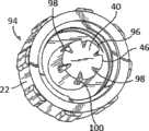
图13是又一替代的冲洗顶部适配器94的透视图,该适配器94具有顶部96和可以任选地被省略的螺纹颈套22,顶部96具有多个流动通道98。在本实施例中,流动通道98包括径向切除部和轴向切除部,同时形成有变窄的侧壁。例如,从各流动通道98的底壁100开始,侧壁朝向交汇部46彼此向内变窄或渐缩。在交汇部46处,径向切除部的侧壁在顶端40的中心点的方向上向内渐缩。因此,应当理解的是,本发明的冲洗顶部适配器94包括多个流动通道98,每个流动通道98包括沿轴向方向的第一梯形切除部和沿径向方向的第二梯形切除部。其中,第一梯形大于第二梯形。尽管示出了六个流动通道98,但也可包括少于或多于六个的流动通道。而且,可包括一个中心端口50。通过在顶部包括本发明的流动通道,适配器构造成产生比从典型的现有技术注射器的中心内腔中流出的单一流体流更宽的喷射或流动型式。13 is a perspective view of yet another alternative flush
图14是又一替代的冲洗顶部适配器102的透视图,该适配器102具有顶部104和可任选地被省略的螺纹颈套22,顶部104具有多个流动通道106。在本实施例中,流动通道106包括径向切除部和轴向切除部,同时形成有变大或发散的侧壁。例如,从各流动通道106的底壁100开始,侧壁朝向交汇部46彼此发散或向外渐扩。在交汇部46处,径向切除部的侧壁在顶端40的中心点的方向上向外渐扩。因此应当理解的是本发明的冲洗顶部适配器94包括多个流动通道106,每个流动通道包括沿轴向方向的第一梯形切除部和沿径向方向的第二梯形切除部。其中,第一梯形小于第二梯形。尽管示出了六个流动通道106,但也可包括少于或多于六个的流动通道。而且,可包括中心端口50。通过在顶部包括本发明的流动通道,适配器构造成产生比从典型的现有技术注射器的中心内腔中流出的单一流体流更宽的喷射或流动型式。14 is a perspective view of yet another alternative flush
图15是根据本发明器械、系统和方法的一些方面提供的替代的冲洗顶部适配器108的剖面侧视图,该适配器108具有顶部110,顶部110具有多个流动通道112,具有可旋转螺纹颈套114。除了可相对于顶部主体54旋转的颈套并且接收端56的尺寸被设计成接收管道以外,冲洗顶部适配器108类似于图4-7的冲洗顶部适配器52。这种装置通常被称为用于滴注管线或延伸管线的适配器。然而,接收端可包括阴型鲁尔圆锥接头。在本实例中,在顶部主体的外表面上设置有锥形的裙部116和凸缘118,在这两者之间限定缺口120。颈套具有带开口124的底部122,该开口124的尺寸被设计成在锥形的裙部116上滑动并且被保持在缺口120处。提供了开口124的弯曲或弓形的鼻部126,以有助于将颈套114组装在锥形的裙部116上。一旦被安装,颈套114被保持在缺口内并且可相对于具有多个流动通道112的顶部主体或顶部110旋转。尽管轴向切除部66通常呈矩形,但切除部构造可以具有一些不同的形状,例如上面所讨论的形状。15 is a cross-sectional side view of an alternative
图16是图15的冲洗顶部适配器108的侧视图,没有示出可旋转螺纹颈套114。在主体130的外表面上可包括多个间隔开的抓持构件128,以有助于抓持。尽管图示为相等间隔的细长条,但抓持构件也可具有其它形状,例如滚圆的或半球形的突出物。在一个实例中,冲洗顶部适配器108被实施为不具有颈套。FIG. 16 is a side view of the flush
为了使用该替代的冲洗顶部适配器108,首先将顶部110插入血管进入器械(例如导管)的阴型接收端,然后使颈套相对于主体130旋转以接合位于血管进入器械上的外螺纹。优选地,在将冲洗顶部适配器108连接到血管进入器械之前,首先将管道附接到主体130的接收端56。如果接收端56装备有阴型鲁尔接头,那么可以将接收端连接到标准注射器。To use the alternative
图17是根据本发明器械、系统和方法的方面提供的帽罩132的剖面侧视图。图中示出的帽罩具有主体134,该主体134具有带螺纹基部136,用于与颈套螺纹接合。帽罩132还包括通气开口138,以允许覆盖例如本文中其它部分所述的注射器或冲洗顶部适配器上的顶部,并且避免气塞。该帽罩的尺寸被设计成接收鲁尔顶部。Figure 17 is a cross-sectional side view of a
图18是附接到冲洗顶部适配器142的导管140的剖面侧视图,该冲洗顶部适配器142代表在正常使用中的冲洗顶部适配器,但没有通常附接到冲洗顶部适配器的接收端56的注射器或其它流体源(例如滴注管线)。图示的导管没有针、针毂和针护套,因此代表了成功的导管插入之后的导管。示例性的安全静脉导管(或IVC)公开于专利号7,736,339、7,374,554、7,625,360、5,879,337和6,629,959以及于2010年2月11日提交的专利公开WO 2010/093792 Al中,前述各专利的内容以参考的方式明确地并入本文中。本文所讨论公开的顶部适配器可用于任何所包括的导管组件。替代地,图1-3的注射器可以直接地连接到无顶部适配器的导管。18 is a cutaway side view of
如图所示,导管140包括导管毂144、导管管道146、能够打开和闭合的阀148以及阀致动器150。美国专利第7,736,339号中描述了类似的导管组件。在冲洗顶部适配器不与导管接合的正常闭合或密封状态下,利用阀148的弹性将阀致动器150推向图18的右侧,并且阀瓣大致竖直地定位以关闭流动开口152。在插入顶部适配器142时,顶部的顶端40邻接阀致动器150并且将该致动器推入阀148中以打开阀,如图18中所示。在如图所示的打开状态下,经过顶部排出的流体以大的流动型式156(由顶部远侧的流动箭头表示)流动经过多个流动通道154。大的流动型式156允许用从注射器或冲洗顶部适配器流出的流体来冲洗内室160。作为比较,现有技术注射器更有可能产生仅由两个内部箭头156表示的流动型式,这是因为来自现有技术注射器的流体将会从位于注射器顶部中的单个中心内腔流出。因此,与由本发明组件和方法的冲洗医疗器械产生的流动型式相比,导管毂144的内室的较少或较小区域将会被较小的流动型式冲洗。流动通道154的尺寸可以被设计成有助于冲洗阴型鲁尔接头的侧面中的凹槽,阀开启器的腿在它们被阳型鲁尔顶部向前推动之前被预先定位在所述凹槽处。类似地,流动通道154的尺寸可以被设计成窄于阀开启器的腿,以便向前推以打开阀接触顶端的至少一部分。As shown,
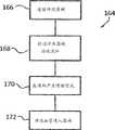
图19是示意性流程图,示出了根据本发明方法的一些方面的使用冲洗医疗器械的方法164。在一个实例中,该方法包括在步骤166将冲洗医疗器械连接到血管进入器械。该方法还包括在步骤168排出或者允许流体经过该冲洗医疗器械。例如,推动柱塞或者对柱塞施加压力以经过注射器的筒体排出流体以使流体经过该冲洗医疗器械排出。替代地,通过重力或者由自动输注装置所产生的压力差来允许流体流动,如上所述,注射器自身可以包括具有多个流动通道的顶端,每个流动通道包括径向布置的切除部和轴向布置的切除部以及自身的冲洗医疗器械。替代地,可将冲洗顶部适配器连接到血管进入装置,并且将预先填满的注射器连接到该冲洗顶部适配器。可用于本发明方法的流体包括抗生素(例如头孢呋辛、头孢曲松、美罗培南、亚胺培南、阿莫西林、Pip/Com、Pip/Tazo、环丙沙星、左旋氧氟沙星、莫西沙星、甲硝唑、万古霉素和达托霉素)、抗真菌药(例如氟康唑、两性霉素B和卡泊芬净)、抗病毒药(例如更昔洛韦和膦甲酸)、长期输注流体(例如KCL、丙泊酚、舒芬太尼、胰岛素、咪达唑仑、尼莫地平、肝素、速尿、谷氨酰胺、氢化可的松、氯胺酮、胺碘酮、乌拉地尔、达那肝素、米利酮和三硝酸甘油酯)、儿茶酚胺类(例如去甲肾上腺素、肾上腺素、多巴胺和多巴酚丁胺)以及急救套组(例如去甲肾上腺素、肾上腺素、吗啡和舒芬太尼)。FIG. 19 is a schematic flow diagram illustrating a
所述方法还包括在步骤170在冲洗医疗器械的顶部形成喷射型式的步骤。该喷射型式大于由具有单个中心内腔的现有技术顶部所形成的典型型式。如上所述,该喷射型式可以由多个流动通道和任选的中心端口形成。该流动型式可以受到每个流动通道的尺寸和流动通道构造(例如矩形、梯形、螺旋形等)的影响。所述方法还包括步骤172:用所产生的喷射型式来冲洗血管进入器械。该喷射型式构造成以比从具有单个中心内腔的顶端产生的流冲洗血管进入器械的更多的内表面区域。The method also includes, at
在另一个实施例中,将具有所公开的带多个流动通道和喷射型式的顶端的注射器用于湿润绷带。对于经过本发明器械的顶部排放的单一流体而言,与从具有单个中心内腔的顶部排放出来的单个流体相比可湿润绷带的更多表面区域。In another embodiment, a syringe having the disclosed tip with multiple flow channels and spray pattern is used to moisten a bandage. A single fluid discharged through the top of the device of the present invention wets more surface area of the bandage than a single fluid discharged from the top with a single central lumen.
尽管本文中已具体描述并说明了注射器组件、冲洗顶部适配器以及它们的部件的有限实施例,但许多修改和变更对于本领域技术人员将是明显的。此外,应当理解的是并且可以想到一种冲洗医疗器械的具体描述的特征可适用于提供这些功能的另一种冲洗医疗器。例如,可以将一种顶部适配器的某个流动通道构造或形状可与另一种流动通道构造相组合,从而在单个冲洗顶端具有多种流动构造。因此,应当理解的是,根据本发明器械、系统和方法的原理所构成的注射器组件、冲洗顶部适配器以及它们的部件,可以在如本文中具体描述以外的方式而实施。本发明也至少部分地限定于所附权利要求中。Although limited embodiments of the syringe assembly, flush tip adapter, and components thereof have been described and illustrated herein in detail, many modifications and variations will be apparent to those skilled in the art. Furthermore, it should be understood and contemplated that features specifically described for one irrigated medical device may be applicable to another irrigated medical device providing these functions. For example, a certain flow channel configuration or shape of one tip adapter can be combined with another flow channel configuration to have multiple flow configurations in a single flush tip. Accordingly, it should be understood that syringe assemblies, flush tip adapters, and components thereof constructed in accordance with the principles of the devices, systems, and methods of the present invention may be practiced otherwise than as specifically described herein. The invention is also defined at least in part in the appended claims.
Claims (18)
Applications Claiming Priority (3)
| Application Number | Priority Date | Filing Date | Title |
|---|---|---|---|
| US201161446821P | 2011-02-25 | 2011-02-25 | |
| US61/446821 | 2011-02-25 | ||
| PCT/EP2012/053070WO2012113865A1 (en) | 2011-02-25 | 2012-02-23 | Flushing medical devices |
Publications (2)
| Publication Number | Publication Date |
|---|---|
| CN103492008Atrue CN103492008A (en) | 2014-01-01 |
| CN103492008B CN103492008B (en) | 2016-11-30 |
Family
ID=
Cited By (3)
| Publication number | Priority date | Publication date | Assignee | Title |
|---|---|---|---|---|
| CN104519944A (en)* | 2012-05-21 | 2015-04-15 | 美国Bd公司 | Flush enhancing male luer tip design for syringes and any luer connector |
| CN108697884A (en)* | 2015-12-04 | 2018-10-23 | Kpr美国有限责任公司 | High Flow Enteral Feeding Syringe Assembly |
| CN111150931A (en)* | 2014-04-23 | 2020-05-15 | 贝克顿·迪金森公司 | Antibacterial cap for medical connector |
Citations (7)
| Publication number | Priority date | Publication date | Assignee | Title |
|---|---|---|---|---|
| US5651776A (en)* | 1995-03-22 | 1997-07-29 | Angiodynamics, Inc. | Luer-type connector |
| US6830563B1 (en)* | 2001-08-24 | 2004-12-14 | Scott Singer | Syringe tip providing nonlaminar spiral flow and method of use for flushing catheters |
| WO2006062912A1 (en)* | 2004-12-10 | 2006-06-15 | Cardinal Health 303, Inc. | Self-sealing male luer connector with multiple seals |
| US20060129109A1 (en)* | 2003-10-28 | 2006-06-15 | Scott Randall Shaw | Reconnectable disconnect device for fluid transfer line |
| CN101460215A (en)* | 2003-12-30 | 2009-06-17 | 瓦索根爱尔兰有限公司 | Valve assembly |
| WO2010109449A1 (en)* | 2009-03-22 | 2010-09-30 | Elcam Medical Agricultural Cooperative Association Ltd. | Closed male luer connector |
| US7842026B2 (en)* | 2005-12-29 | 2010-11-30 | Nmt Medical, Inc. | Syringe activated-valve for flushing a catheter and methods thereof |
Patent Citations (7)
| Publication number | Priority date | Publication date | Assignee | Title |
|---|---|---|---|---|
| US5651776A (en)* | 1995-03-22 | 1997-07-29 | Angiodynamics, Inc. | Luer-type connector |
| US6830563B1 (en)* | 2001-08-24 | 2004-12-14 | Scott Singer | Syringe tip providing nonlaminar spiral flow and method of use for flushing catheters |
| US20060129109A1 (en)* | 2003-10-28 | 2006-06-15 | Scott Randall Shaw | Reconnectable disconnect device for fluid transfer line |
| CN101460215A (en)* | 2003-12-30 | 2009-06-17 | 瓦索根爱尔兰有限公司 | Valve assembly |
| WO2006062912A1 (en)* | 2004-12-10 | 2006-06-15 | Cardinal Health 303, Inc. | Self-sealing male luer connector with multiple seals |
| US7842026B2 (en)* | 2005-12-29 | 2010-11-30 | Nmt Medical, Inc. | Syringe activated-valve for flushing a catheter and methods thereof |
| WO2010109449A1 (en)* | 2009-03-22 | 2010-09-30 | Elcam Medical Agricultural Cooperative Association Ltd. | Closed male luer connector |
Cited By (7)
| Publication number | Priority date | Publication date | Assignee | Title |
|---|---|---|---|---|
| CN104519944A (en)* | 2012-05-21 | 2015-04-15 | 美国Bd公司 | Flush enhancing male luer tip design for syringes and any luer connector |
| US9616214B2 (en) | 2012-05-21 | 2017-04-11 | Becton, Dickinson And Company | Flush enhancing male luer tip design for syringes and any luer connector |
| CN104519944B (en)* | 2012-05-21 | 2018-02-06 | 美国Bd公司 | Flushing for syringe and any luer connector strengthens male Luer tip design |
| US10272237B2 (en) | 2012-05-21 | 2019-04-30 | Becton, Dickinson And Company | Flush enhancing male luer tip design for syringes and any luer connection |
| US11779745B2 (en) | 2012-05-21 | 2023-10-10 | Becton, Dickinson And Company | Flush enhancing male luer tip design for syringes and any luer connector |
| CN111150931A (en)* | 2014-04-23 | 2020-05-15 | 贝克顿·迪金森公司 | Antibacterial cap for medical connector |
| CN108697884A (en)* | 2015-12-04 | 2018-10-23 | Kpr美国有限责任公司 | High Flow Enteral Feeding Syringe Assembly |
Also Published As
| Publication number | Publication date |
|---|---|
| EP2678057B1 (en) | 2017-01-18 |
| BR112013021489A2 (en) | 2016-10-11 |
| EP2678057A1 (en) | 2014-01-01 |
| BR112013021489B1 (en) | 2021-02-02 |
| US9399098B2 (en) | 2016-07-26 |
| CA2826206A1 (en) | 2012-08-30 |
| RU2013143305A (en) | 2015-03-27 |
| WO2012113865A1 (en) | 2012-08-30 |
| US20130331817A1 (en) | 2013-12-12 |
Similar Documents
| Publication | Publication Date | Title |
|---|---|---|
| US9399098B2 (en) | Flushing medical devices | |
| US12311149B2 (en) | Flush syringe with flip cap | |
| JP6976932B2 (en) | Priming device | |
| JP6706675B2 (en) | System and method for flared luer connector for medical tubing | |
| JP4682850B2 (en) | Prefilled syringe | |
| US8672894B2 (en) | Protection device for a needle | |
| US20130253448A1 (en) | Hypodermic Needle With Multiple Dispersement Openings | |
| JP6932152B2 (en) | Adapter for needleless access device and how to connect the device to it | |
| BRPI0807174A2 (en) | SYRINGE SET HAVING DISABILITY MECHANISM | |
| JP2007185319A5 (en) | ||
| US20160235961A1 (en) | Needle-free connector | |
| KR102645428B1 (en) | female connector | |
| EP3342440B1 (en) | Medical device, assembly including said medical device and process for manufacturing such a medical device | |
| JP7728311B2 (en) | Shielded Tip Irrigation Syringe | |
| WO2017057476A1 (en) | Medical resin-made hollow needle, medical instrument set using same, and outer cylinder provided with puncture part | |
| CN103492008B (en) | flushing medical equipment | |
| JP7660071B2 (en) | Retention element for partially pre-filled syringes to prevent break-loose contamination | |
| JP7111747B2 (en) | Cap hub interface for intradermal injection device | |
| HK1188744A (en) | Flushing medical devices | |
| JP2008099728A (en) | Syringe serving also as container | |
| US20240226435A9 (en) | Low Dead Volume Adaptor for a Syringe | |
| US20240342394A1 (en) | Syringe Having Combined Luer Lock And Pen Needle Attachment Capability | |
| KR102675223B1 (en) | Syringe with multi-function needle holder and retainer ring assembly | |
| CN118660728A (en) | Syringe with minimal internal dead volume |
Legal Events
| Date | Code | Title | Description |
|---|---|---|---|
| C06 | Publication | ||
| PB01 | Publication | ||
| SE01 | Entry into force of request for substantive examination | ||
| SE01 | Entry into force of request for substantive examination | ||
| REG | Reference to a national code | Ref country code:HK Ref legal event code:DE Ref document number:1188744 Country of ref document:HK | |
| C14 | Grant of patent or utility model | ||
| GR01 | Patent grant | ||
| REG | Reference to a national code | Ref country code:HK Ref legal event code:WD Ref document number:1188744 Country of ref document:HK |