CN103492001A - Auto-injector - Google Patents
Auto-injectorDownload PDFInfo
- Publication number
- CN103492001A CN103492001ACN201280019032.5ACN201280019032ACN103492001ACN 103492001 ACN103492001 ACN 103492001ACN 201280019032 ACN201280019032 ACN 201280019032ACN 103492001 ACN103492001 ACN 103492001A
- Authority
- CN
- China
- Prior art keywords
- carrier
- housing
- collar
- clip
- frame
- Prior art date
- Legal status (The legal status is an assumption and is not a legal conclusion. Google has not performed a legal analysis and makes no representation as to the accuracy of the status listed.)
- Granted
Links
Images


Classifications
- A—HUMAN NECESSITIES
- A61—MEDICAL OR VETERINARY SCIENCE; HYGIENE
- A61M—DEVICES FOR INTRODUCING MEDIA INTO, OR ONTO, THE BODY; DEVICES FOR TRANSDUCING BODY MEDIA OR FOR TAKING MEDIA FROM THE BODY; DEVICES FOR PRODUCING OR ENDING SLEEP OR STUPOR
- A61M5/00—Devices for bringing media into the body in a subcutaneous, intra-vascular or intramuscular way; Accessories therefor, e.g. filling or cleaning devices, arm-rests
- A61M5/178—Syringes
- A61M5/31—Details
- A61M5/315—Pistons; Piston-rods; Guiding, blocking or restricting the movement of the rod or piston; Appliances on the rod for facilitating dosing ; Dosing mechanisms
- A61M5/31565—Administration mechanisms, i.e. constructional features, modes of administering a dose
- A61M5/31566—Means improving security or handling thereof
- A61M5/3157—Means providing feedback signals when administration is completed
- A—HUMAN NECESSITIES
- A61—MEDICAL OR VETERINARY SCIENCE; HYGIENE
- A61M—DEVICES FOR INTRODUCING MEDIA INTO, OR ONTO, THE BODY; DEVICES FOR TRANSDUCING BODY MEDIA OR FOR TAKING MEDIA FROM THE BODY; DEVICES FOR PRODUCING OR ENDING SLEEP OR STUPOR
- A61M5/00—Devices for bringing media into the body in a subcutaneous, intra-vascular or intramuscular way; Accessories therefor, e.g. filling or cleaning devices, arm-rests
- A61M5/178—Syringes
- A61M5/20—Automatic syringes, e.g. with automatically actuated piston rod, with automatic needle injection, filling automatically
- A61M5/2033—Spring-loaded one-shot injectors with or without automatic needle insertion
- A—HUMAN NECESSITIES
- A61—MEDICAL OR VETERINARY SCIENCE; HYGIENE
- A61M—DEVICES FOR INTRODUCING MEDIA INTO, OR ONTO, THE BODY; DEVICES FOR TRANSDUCING BODY MEDIA OR FOR TAKING MEDIA FROM THE BODY; DEVICES FOR PRODUCING OR ENDING SLEEP OR STUPOR
- A61M5/00—Devices for bringing media into the body in a subcutaneous, intra-vascular or intramuscular way; Accessories therefor, e.g. filling or cleaning devices, arm-rests
- A61M5/178—Syringes
- A61M5/24—Ampoule syringes, i.e. syringes with needle for use in combination with replaceable ampoules or carpules, e.g. automatic
- A61M5/2422—Ampoule syringes, i.e. syringes with needle for use in combination with replaceable ampoules or carpules, e.g. automatic using emptying means to expel or eject media, e.g. pistons, deformation of the ampoule, or telescoping of the ampoule
- A61M5/2429—Ampoule syringes, i.e. syringes with needle for use in combination with replaceable ampoules or carpules, e.g. automatic using emptying means to expel or eject media, e.g. pistons, deformation of the ampoule, or telescoping of the ampoule by telescoping of ampoules or carpules with the syringe body
- A—HUMAN NECESSITIES
- A61—MEDICAL OR VETERINARY SCIENCE; HYGIENE
- A61M—DEVICES FOR INTRODUCING MEDIA INTO, OR ONTO, THE BODY; DEVICES FOR TRANSDUCING BODY MEDIA OR FOR TAKING MEDIA FROM THE BODY; DEVICES FOR PRODUCING OR ENDING SLEEP OR STUPOR
- A61M5/00—Devices for bringing media into the body in a subcutaneous, intra-vascular or intramuscular way; Accessories therefor, e.g. filling or cleaning devices, arm-rests
- A61M5/178—Syringes
- A61M5/31—Details
- A61M5/315—Pistons; Piston-rods; Guiding, blocking or restricting the movement of the rod or piston; Appliances on the rod for facilitating dosing ; Dosing mechanisms
- A61M5/31501—Means for blocking or restricting the movement of the rod or piston
- A—HUMAN NECESSITIES
- A61—MEDICAL OR VETERINARY SCIENCE; HYGIENE
- A61M—DEVICES FOR INTRODUCING MEDIA INTO, OR ONTO, THE BODY; DEVICES FOR TRANSDUCING BODY MEDIA OR FOR TAKING MEDIA FROM THE BODY; DEVICES FOR PRODUCING OR ENDING SLEEP OR STUPOR
- A61M5/00—Devices for bringing media into the body in a subcutaneous, intra-vascular or intramuscular way; Accessories therefor, e.g. filling or cleaning devices, arm-rests
- A61M5/178—Syringes
- A61M5/31—Details
- A61M5/315—Pistons; Piston-rods; Guiding, blocking or restricting the movement of the rod or piston; Appliances on the rod for facilitating dosing ; Dosing mechanisms
- A61M5/31511—Piston or piston-rod constructions, e.g. connection of piston with piston-rod
- A—HUMAN NECESSITIES
- A61—MEDICAL OR VETERINARY SCIENCE; HYGIENE
- A61M—DEVICES FOR INTRODUCING MEDIA INTO, OR ONTO, THE BODY; DEVICES FOR TRANSDUCING BODY MEDIA OR FOR TAKING MEDIA FROM THE BODY; DEVICES FOR PRODUCING OR ENDING SLEEP OR STUPOR
- A61M5/00—Devices for bringing media into the body in a subcutaneous, intra-vascular or intramuscular way; Accessories therefor, e.g. filling or cleaning devices, arm-rests
- A61M5/178—Syringes
- A61M5/31—Details
- A61M5/315—Pistons; Piston-rods; Guiding, blocking or restricting the movement of the rod or piston; Appliances on the rod for facilitating dosing ; Dosing mechanisms
- A61M5/31565—Administration mechanisms, i.e. constructional features, modes of administering a dose
- A61M5/31576—Constructional features or modes of drive mechanisms for piston rods
- A61M5/31578—Constructional features or modes of drive mechanisms for piston rods based on axial translation, i.e. components directly operatively associated and axially moved with plunger rod
- A61M5/3158—Constructional features or modes of drive mechanisms for piston rods based on axial translation, i.e. components directly operatively associated and axially moved with plunger rod performed by axially moving actuator operated by user, e.g. an injection button
- A—HUMAN NECESSITIES
- A61—MEDICAL OR VETERINARY SCIENCE; HYGIENE
- A61M—DEVICES FOR INTRODUCING MEDIA INTO, OR ONTO, THE BODY; DEVICES FOR TRANSDUCING BODY MEDIA OR FOR TAKING MEDIA FROM THE BODY; DEVICES FOR PRODUCING OR ENDING SLEEP OR STUPOR
- A61M5/00—Devices for bringing media into the body in a subcutaneous, intra-vascular or intramuscular way; Accessories therefor, e.g. filling or cleaning devices, arm-rests
- A61M5/178—Syringes
- A61M5/31—Details
- A61M5/32—Needles; Details of needles pertaining to their connection with syringe or hub; Accessories for bringing the needle into, or holding the needle on, the body; Devices for protection of needles
- A61M5/3202—Devices for protection of the needle before use, e.g. caps
- A61M5/3204—Needle cap remover, i.e. devices to dislodge protection cover from needle or needle hub, e.g. deshielding devices
- A—HUMAN NECESSITIES
- A61—MEDICAL OR VETERINARY SCIENCE; HYGIENE
- A61M—DEVICES FOR INTRODUCING MEDIA INTO, OR ONTO, THE BODY; DEVICES FOR TRANSDUCING BODY MEDIA OR FOR TAKING MEDIA FROM THE BODY; DEVICES FOR PRODUCING OR ENDING SLEEP OR STUPOR
- A61M5/00—Devices for bringing media into the body in a subcutaneous, intra-vascular or intramuscular way; Accessories therefor, e.g. filling or cleaning devices, arm-rests
- A61M5/178—Syringes
- A61M5/31—Details
- A61M5/32—Needles; Details of needles pertaining to their connection with syringe or hub; Accessories for bringing the needle into, or holding the needle on, the body; Devices for protection of needles
- A61M5/3205—Apparatus for removing or disposing of used needles or syringes, e.g. containers; Means for protection against accidental injuries from used needles
- A61M5/321—Means for protection against accidental injuries by used needles
- A61M5/3243—Means for protection against accidental injuries by used needles being axially-extensible, e.g. protective sleeves coaxially slidable on the syringe barrel
- A61M5/3257—Semi-automatic sleeve extension, i.e. in which triggering of the sleeve extension requires a deliberate action by the user, e.g. manual release of spring-biased extension means
- A—HUMAN NECESSITIES
- A61—MEDICAL OR VETERINARY SCIENCE; HYGIENE
- A61M—DEVICES FOR INTRODUCING MEDIA INTO, OR ONTO, THE BODY; DEVICES FOR TRANSDUCING BODY MEDIA OR FOR TAKING MEDIA FROM THE BODY; DEVICES FOR PRODUCING OR ENDING SLEEP OR STUPOR
- A61M5/00—Devices for bringing media into the body in a subcutaneous, intra-vascular or intramuscular way; Accessories therefor, e.g. filling or cleaning devices, arm-rests
- A61M5/178—Syringes
- A61M5/31—Details
- A61M5/32—Needles; Details of needles pertaining to their connection with syringe or hub; Accessories for bringing the needle into, or holding the needle on, the body; Devices for protection of needles
- A61M5/3205—Apparatus for removing or disposing of used needles or syringes, e.g. containers; Means for protection against accidental injuries from used needles
- A61M5/321—Means for protection against accidental injuries by used needles
- A61M5/3243—Means for protection against accidental injuries by used needles being axially-extensible, e.g. protective sleeves coaxially slidable on the syringe barrel
- A61M5/326—Fully automatic sleeve extension, i.e. in which triggering of the sleeve does not require a deliberate action by the user
- A—HUMAN NECESSITIES
- A61—MEDICAL OR VETERINARY SCIENCE; HYGIENE
- A61M—DEVICES FOR INTRODUCING MEDIA INTO, OR ONTO, THE BODY; DEVICES FOR TRANSDUCING BODY MEDIA OR FOR TAKING MEDIA FROM THE BODY; DEVICES FOR PRODUCING OR ENDING SLEEP OR STUPOR
- A61M5/00—Devices for bringing media into the body in a subcutaneous, intra-vascular or intramuscular way; Accessories therefor, e.g. filling or cleaning devices, arm-rests
- A61M5/178—Syringes
- A61M5/20—Automatic syringes, e.g. with automatically actuated piston rod, with automatic needle injection, filling automatically
- A61M2005/2006—Having specific accessories
- A61M2005/2013—Having specific accessories triggering of discharging means by contact of injector with patient body
- A—HUMAN NECESSITIES
- A61—MEDICAL OR VETERINARY SCIENCE; HYGIENE
- A61M—DEVICES FOR INTRODUCING MEDIA INTO, OR ONTO, THE BODY; DEVICES FOR TRANSDUCING BODY MEDIA OR FOR TAKING MEDIA FROM THE BODY; DEVICES FOR PRODUCING OR ENDING SLEEP OR STUPOR
- A61M5/00—Devices for bringing media into the body in a subcutaneous, intra-vascular or intramuscular way; Accessories therefor, e.g. filling or cleaning devices, arm-rests
- A61M5/178—Syringes
- A61M5/20—Automatic syringes, e.g. with automatically actuated piston rod, with automatic needle injection, filling automatically
- A61M2005/206—With automatic needle insertion
- A—HUMAN NECESSITIES
- A61—MEDICAL OR VETERINARY SCIENCE; HYGIENE
- A61M—DEVICES FOR INTRODUCING MEDIA INTO, OR ONTO, THE BODY; DEVICES FOR TRANSDUCING BODY MEDIA OR FOR TAKING MEDIA FROM THE BODY; DEVICES FOR PRODUCING OR ENDING SLEEP OR STUPOR
- A61M5/00—Devices for bringing media into the body in a subcutaneous, intra-vascular or intramuscular way; Accessories therefor, e.g. filling or cleaning devices, arm-rests
- A61M5/178—Syringes
- A61M5/20—Automatic syringes, e.g. with automatically actuated piston rod, with automatic needle injection, filling automatically
- A61M2005/2073—Automatic syringes, e.g. with automatically actuated piston rod, with automatic needle injection, filling automatically preventing premature release, e.g. by making use of a safety lock
- A61M2005/208—Release is possible only when device is pushed against the skin, e.g. using a trigger which is blocked or inactive when the device is not pushed against the skin
- A—HUMAN NECESSITIES
- A61—MEDICAL OR VETERINARY SCIENCE; HYGIENE
- A61M—DEVICES FOR INTRODUCING MEDIA INTO, OR ONTO, THE BODY; DEVICES FOR TRANSDUCING BODY MEDIA OR FOR TAKING MEDIA FROM THE BODY; DEVICES FOR PRODUCING OR ENDING SLEEP OR STUPOR
- A61M5/00—Devices for bringing media into the body in a subcutaneous, intra-vascular or intramuscular way; Accessories therefor, e.g. filling or cleaning devices, arm-rests
- A61M5/178—Syringes
- A61M5/31—Details
- A61M5/32—Needles; Details of needles pertaining to their connection with syringe or hub; Accessories for bringing the needle into, or holding the needle on, the body; Devices for protection of needles
- A61M5/3205—Apparatus for removing or disposing of used needles or syringes, e.g. containers; Means for protection against accidental injuries from used needles
- A61M5/321—Means for protection against accidental injuries by used needles
- A61M5/3243—Means for protection against accidental injuries by used needles being axially-extensible, e.g. protective sleeves coaxially slidable on the syringe barrel
- A61M5/3245—Constructional features thereof, e.g. to improve manipulation or functioning
- A61M2005/3247—Means to impede repositioning of protection sleeve from needle covering to needle uncovering position
- A—HUMAN NECESSITIES
- A61—MEDICAL OR VETERINARY SCIENCE; HYGIENE
- A61M—DEVICES FOR INTRODUCING MEDIA INTO, OR ONTO, THE BODY; DEVICES FOR TRANSDUCING BODY MEDIA OR FOR TAKING MEDIA FROM THE BODY; DEVICES FOR PRODUCING OR ENDING SLEEP OR STUPOR
- A61M2205/00—General characteristics of the apparatus
- A61M2205/58—Means for facilitating use, e.g. by people with impaired vision
- A61M2205/581—Means for facilitating use, e.g. by people with impaired vision by audible feedback
- A—HUMAN NECESSITIES
- A61—MEDICAL OR VETERINARY SCIENCE; HYGIENE
- A61M—DEVICES FOR INTRODUCING MEDIA INTO, OR ONTO, THE BODY; DEVICES FOR TRANSDUCING BODY MEDIA OR FOR TAKING MEDIA FROM THE BODY; DEVICES FOR PRODUCING OR ENDING SLEEP OR STUPOR
- A61M2205/00—General characteristics of the apparatus
- A61M2205/58—Means for facilitating use, e.g. by people with impaired vision
- A61M2205/582—Means for facilitating use, e.g. by people with impaired vision by tactile feedback
- A—HUMAN NECESSITIES
- A61—MEDICAL OR VETERINARY SCIENCE; HYGIENE
- A61M—DEVICES FOR INTRODUCING MEDIA INTO, OR ONTO, THE BODY; DEVICES FOR TRANSDUCING BODY MEDIA OR FOR TAKING MEDIA FROM THE BODY; DEVICES FOR PRODUCING OR ENDING SLEEP OR STUPOR
- A61M2205/00—General characteristics of the apparatus
- A61M2205/58—Means for facilitating use, e.g. by people with impaired vision
- A61M2205/583—Means for facilitating use, e.g. by people with impaired vision by visual feedback
- A—HUMAN NECESSITIES
- A61—MEDICAL OR VETERINARY SCIENCE; HYGIENE
- A61M—DEVICES FOR INTRODUCING MEDIA INTO, OR ONTO, THE BODY; DEVICES FOR TRANSDUCING BODY MEDIA OR FOR TAKING MEDIA FROM THE BODY; DEVICES FOR PRODUCING OR ENDING SLEEP OR STUPOR
- A61M5/00—Devices for bringing media into the body in a subcutaneous, intra-vascular or intramuscular way; Accessories therefor, e.g. filling or cleaning devices, arm-rests
- A61M5/46—Devices for bringing media into the body in a subcutaneous, intra-vascular or intramuscular way; Accessories therefor, e.g. filling or cleaning devices, arm-rests having means for controlling depth of insertion
- A—HUMAN NECESSITIES
- A61—MEDICAL OR VETERINARY SCIENCE; HYGIENE
- A61M—DEVICES FOR INTRODUCING MEDIA INTO, OR ONTO, THE BODY; DEVICES FOR TRANSDUCING BODY MEDIA OR FOR TAKING MEDIA FROM THE BODY; DEVICES FOR PRODUCING OR ENDING SLEEP OR STUPOR
- A61M5/00—Devices for bringing media into the body in a subcutaneous, intra-vascular or intramuscular way; Accessories therefor, e.g. filling or cleaning devices, arm-rests
- A61M5/50—Devices for bringing media into the body in a subcutaneous, intra-vascular or intramuscular way; Accessories therefor, e.g. filling or cleaning devices, arm-rests having means for preventing re-use, or for indicating if defective, used, tampered with or unsterile
- A61M5/5086—Devices for bringing media into the body in a subcutaneous, intra-vascular or intramuscular way; Accessories therefor, e.g. filling or cleaning devices, arm-rests having means for preventing re-use, or for indicating if defective, used, tampered with or unsterile for indicating if defective, used, tampered with or unsterile
- F—MECHANICAL ENGINEERING; LIGHTING; HEATING; WEAPONS; BLASTING
- F04—POSITIVE - DISPLACEMENT MACHINES FOR LIQUIDS; PUMPS FOR LIQUIDS OR ELASTIC FLUIDS
- F04C—ROTARY-PISTON, OR OSCILLATING-PISTON, POSITIVE-DISPLACEMENT MACHINES FOR LIQUIDS; ROTARY-PISTON, OR OSCILLATING-PISTON, POSITIVE-DISPLACEMENT PUMPS
- F04C2270/00—Control; Monitoring or safety arrangements
- F04C2270/04—Force
- F04C2270/042—Force radial
- F04C2270/0421—Controlled or regulated
- Y—GENERAL TAGGING OF NEW TECHNOLOGICAL DEVELOPMENTS; GENERAL TAGGING OF CROSS-SECTIONAL TECHNOLOGIES SPANNING OVER SEVERAL SECTIONS OF THE IPC; TECHNICAL SUBJECTS COVERED BY FORMER USPC CROSS-REFERENCE ART COLLECTIONS [XRACs] AND DIGESTS
- Y10—TECHNICAL SUBJECTS COVERED BY FORMER USPC
- Y10T—TECHNICAL SUBJECTS COVERED BY FORMER US CLASSIFICATION
- Y10T403/00—Joints and connections
- Y10T403/32—Articulated members
- Y10T403/32254—Lockable at fixed position
- Y10T403/32467—Telescoping members
- Y10T403/32475—Telescoping members having detent
- Y10T403/32501—Cam or wedge
Landscapes
- Health & Medical Sciences (AREA)
- Engineering & Computer Science (AREA)
- Hematology (AREA)
- Anesthesiology (AREA)
- Biomedical Technology (AREA)
- Heart & Thoracic Surgery (AREA)
- Vascular Medicine (AREA)
- Life Sciences & Earth Sciences (AREA)
- Animal Behavior & Ethology (AREA)
- General Health & Medical Sciences (AREA)
- Public Health (AREA)
- Veterinary Medicine (AREA)
- Environmental & Geological Engineering (AREA)
- Infusion, Injection, And Reservoir Apparatuses (AREA)
Abstract
Translated fromChineseDescription
Translated fromChinese技术领域technical field
本发明涉及根据权利要求1的前序部分所述的用于给送液体药剂的剂量的自动注射装置。The invention relates to an automatic injection device for administering doses of liquid medicaments according to the preamble of
背景技术Background technique
对于使用者和医护专业人员来说,给送注射剂在心理上和身体上都意味着许多风险和挑战。Administering injectables presents many risks and challenges, both psychologically and physically, for users and healthcare professionals.
注射装置(即能够从药剂容器递送药剂的装置)典型地分成两种类型-手动装置和自动注射装置。Injection devices (ie, devices capable of delivering medicament from a medicament container) typically fall into two types - manual devices and automatic injection devices.
在手动装置中,使用者必须提供机械能来驱动流体通过针头。这典型地通过某种形式的按钮/柱塞来完成,在注射期间,使用者必需连续地按压所述按钮/柱塞。该方案对于使用者存在许多缺陷。如果使用者停止按压所述按钮/柱塞,则注射将同样停止。这意味着如果装置未被适当使用(即,柱塞未被完全地按压到其终点位置),则使用者会递送不足的剂量。注射力对于使用者可能过高,特别是如果患者年长或者具有灵活性问题时。In manual devices, the user must provide mechanical energy to drive fluid through the needle. This is typically done with some form of button/plunger which the user must continuously depress during an injection. This solution has a number of drawbacks for the user. If the user stops pressing the button/plunger, the injection will also stop. This means that if the device is not used properly (ie the plunger is not fully depressed to its end position), the user will deliver an insufficient dose. The injection force may be too high for the user, especially if the patient is elderly or has dexterity issues.
按钮/柱塞的伸展可能太大。由此,到达充分伸展的按钮对于使用者会是不方便的。注射力和按钮伸展的综合能够导致手部的发抖/摇振,这又随着插入的针头移动加剧了不适感。The button/plunger may be stretched too much. Thus, reaching the fully extended button can be inconvenient for the user. The combination of injection force and button extension can cause trembling/shaking of the hand, which in turn exacerbates discomfort as the inserted needle moves.
自动注射装置目的在于使得注射药方的自我给送对于患者更容易。当前借助于自我给送注射剂递送的药方包括用于糖尿病(胰岛素和新的GLP-1类药物)、偏头痛的药物、激素药方、抗凝血剂等等。Automatic injection devices aim to make self-administration of injectable medication easier for patients. Medications currently delivered by means of self-administering injections include medications for diabetes (insulin and the new GLP-1 class of drugs), migraine medications, hormonal medications, anticoagulants, and more.
自动注射装置是这样的装置,该装置完全地或者部分地代替了来自标准注射器的注射用药物递送的活动。这些活动可以包括:移除注射器保护盖,将针头插入患者皮肤,注射药剂,移除针头,防护针头,并且防止装置的重复使用。这克服了手动装置的许多缺陷。降低了注射力/按钮伸展、手部摇振以及递送不完全剂量的可能性。触发可以通过许多手段执行,例如触发按钮或者针头到达其注射深度的动作。在一些装置中,通过弹簧提供递送流体的能量。An automatic injection device is a device that completely or partially replaces the action of injectable drug delivery from a standard syringe. These activities may include: removing the syringe protective cap, inserting the needle into the patient's skin, injecting the medicament, removing the needle, securing the needle, and preventing re-use of the device. This overcomes many of the drawbacks of manual devices. Reduced injection force/button extension, hand shaking, and the possibility of incomplete dose delivery. Triggering can be performed by many means, such as a trigger button or the action of a needle reaching its injection depth. In some devices, the energy to deliver the fluid is provided by a spring.
US2002/0095120A1公开了一种自动化的注射装置,该注射装置在拉伸弹簧释放时自动地注射预先测定量的流体药物。拉伸弹簧在其释放时使针头药管(ampoule)和注射针头从储存位置移动至展开位置。针头药管的内容物通过拉伸弹簧迫使活塞在针头药管中向前而被排出。在流体药物已被注射之后,储存在拉伸弹簧中的扭力被释放,并且注射针头自动地退回到其起始的储存位置。US2002/0095120A1 discloses an automated injection device that automatically injects a pre-measured amount of fluid medicament upon release of a tension spring. The tension spring moves the needle ampoule and injection needle from the stored position to the deployed position when it is released. The contents of the needle cartridge are expelled by the tension spring forcing the plunger forward in the needle cartridge. After the fluid drug has been injected, the torque stored in the tension spring is released and the injection needle automatically retracts to its original stored position.
高粘度药剂要求大的力以用于将它们经过相对细的注射针头排出。为实现这些力,需要强的驱动弹簧。这可能导致当针头插入皮肤时使用者感受到的大的冲击,以及当触发注射时使用者感受到的大的力。High viscosity medicaments require high forces for expelling them through relatively thin injection needles. To achieve these forces, strong drive springs are required. This can result in a large shock felt by the user when the needle is inserted into the skin, and a large force felt by the user when the injection is triggered.
发明内容Contents of the invention
本发明的目的是提供一种改进的自动注射装置。It is an object of the present invention to provide an improved automatic injection device.
此目的由根据权利要求1的自动注射装置实现。This object is achieved by an automatic injection device according to
本发明的优选实施例由从属权利要求给出。Preferred embodiments of the invention are given by the dependent claims.
在本说明书的上下文中,术语“近侧”是指在注射期间指向患者的方向,而术语“远侧”是指背离患者指向的相反方向。术语“向内”是指指向自动注射装置的纵向轴线的径向方向,而术语“向外”是指在径向上背离纵向轴线的相反方向。In the context of this specification, the term "proximal" refers to the direction pointing towards the patient during injection, while the term "distal" refers to the opposite direction pointing away from the patient. The term "inwardly" refers to a radial direction pointing towards the longitudinal axis of the automatic injection device, while the term "outwardly" refers to the opposite direction radially away from the longitudinal axis.
根据本发明,一种用于给送液体药剂剂量的自动注射装置包括:According to the invention, an automatic injection device for administering a dose of a liquid medicament comprises:
-在长形机架中可伸缩的管状机架,- Telescoping tubular racks in elongated racks,
-承载件子组件,包括可滑动地布置成部分在所述机架内部和在所述机壳内部的管状承载件,所述承载件适于容纳带中空注射针头的注射器、驱动弹簧、和用于将所述驱动弹簧的载荷递送到所述注射器的封堵器的柱塞,其中所述注射器可锁定用于与所述承载件联合轴向平移,- a carrier subassembly comprising a tubular carrier slidably arranged partly inside said frame and inside said casing, said carrier being adapted to accommodate a syringe with a hollow injection needle, a drive spring, and a for delivering the load of the drive spring to the plunger of the occluder of the syringe, wherein the syringe is lockable for axial translation in conjunction with the carrier,
-布置在所述承载件周围的控制弹簧,- a control spring arranged around said carrier,
-针头插入控制机构,用于将所述控制弹簧的近端联接到所述承载件以使它推进用于针头插入或联接到所述机架。- a needle insertion control mechanism for coupling the proximal end of the control spring to the carrier to advance it for needle insertion or to the housing.
在此说明书的上下文中,除特别声明外,机架大体上被认为是固定在位,由此其它部件的运动相对于所述机架而描述。In the context of this specification, unless otherwise stated, the frame is generally considered to be fixed in position, whereby the movement of other components is described relative to the frame.
所述针头插入控制机构包括由所述控制弹簧沿近端方向偏压的第一套环,其中至少一个第五夹子布置在所述第一套环或所述机架中的一者上,起始地邻接所述第一套环或所述机架中的另一者上的块,其中所述第五夹子与所述承载件之间的斜面接合被提供用于在所述承载件沿近端方向平移时向外偏转所述第五夹子,其中所述第五夹子的向外偏转和所述承载件沿近端方向的平移起始地由在外部邻接所述第五夹子的所述机壳阻止,其中所述机壳至少起始地被沿远端方向偏压,其中所述机壳布置成抵抗所述偏压沿近端方向相对于所述机架平移到推进位置,例如当机架被压靠在注射部位时,由此将所述机壳中的第二窗口在所述第五夹子的后方向外平移,以此允许向外偏转,以便使所述第五夹子脱离所述块以及允许所述第一套环邻接抵靠于所述承载件并在所述控制弹簧的载荷下推进它,例如用于针头插入。除将所述控制弹簧切换至所述承载件用于使针头推进之外,所述第五夹子的向外偏转还提供掣子。所述掣子用于提供使所述承载件沿近端方向推进用于针头插入所须克服的阻力。一旦使用者在触发按钮上施加超过预定值的力,则所述第五夹子释放,从而开启注射周期。如果所述预定值未得以克服,则所述掣子将所述承载件和触发按钮推回到它们的先前位置中。这确保:所述自动注射装置总是处于确定的状态,触发的或未触发的,而不因使用者犹豫而被半触发。The needle insertion control mechanism includes a first collar biased in a proximal direction by the control spring, wherein at least one fifth clip is disposed on one of the first collar or the housing, thereby Initially abutting a block on the other of the first collar or the frame, wherein a beveled engagement between the fifth clip and the carrier is provided for running along the carrier near outward deflection of the fifth clip during end-direction translation, wherein the outward deflection of the fifth clip and translation of the carrier in the proximal direction is initiated by the mechanism externally adjoining the fifth clip The housing blocks, wherein the housing is at least initially biased in the distal direction, wherein the housing is arranged to translate relative to the frame in the proximal direction against the bias to an advanced position, for example when the housing The frame is pressed against the injection site, thereby translating the second window in the housing outwardly behind the fifth clip, thereby allowing outward deflection to disengage the fifth clip from the block and allow the first collar to abut against the carrier and advance it under the load of the control spring, eg for needle insertion. The outward deflection of the fifth clip provides a detent in addition to switching the control spring to the carrier for needle advancement. The detent is used to provide a resistance to be overcome to advance the carrier in the proximal direction for needle insertion. Once the user exerts a force on the trigger button exceeding a predetermined value, the fifth clip is released, thereby initiating the injection cycle. If the predetermined value is not overcome, the detent pushes the carrier and trigger button back into their previous positions. This ensures that the automatic injection device is always in a defined state, triggered or not, and is not half-triggered due to user hesitation.
所述第一套环包括第四夹子,第四夹子用于接合所述承载件上的第四肋以用于针头插入。第四肋和所述第四夹子中的至少一者是带斜面的,以便向外偏转所述第四夹子以用于在所述控制弹簧的载荷下使所述第四夹子与所述第四肋分离,其中所述第四夹子的向外偏转起始地由所述机壳阻止,其中所述机壳被允许在所述自动注射装置被从所述注射部位提起时由所述控制弹簧驱动而沿远端方向从所述推进位置平移,由此将所述机壳中的第六凹部在所述第四夹子的后方向外平移,以允许向外偏转,以便使所述第一套环脱离于所述承载件,继而允许所述第一套环邻接所述机架。将所述承载件分离于控制弹簧的近端,这允许将所述承载件以及所述针头退回到针头安全位置中。这可由单独的退回弹簧或由所述控制弹簧实现,后者将要求将控制弹簧的远端联接到所述承载件。当使用单独的退回弹簧时,所述控制弹簧的近端不必被切换到所述机架。除所述控制弹簧切换到所述机架以允许针头退回之外,所述第四夹子的向外偏转提供了掣子。所述掣子用于提供阻力,抵抗所述承载件相对于所述机架沿远端方向的平移、用于将所述承载件在其中所述控制弹簧的两端脱离于所述承载件的过渡状态保持在确定位置。此过渡状态可能是在移离注射部位时将针头退回所需要的。因为所述承载件在移离注射部位前被控制弹簧偏压抵靠注射部位,所以它需脱离控制弹簧的近端并且联接到远端用于退回。此切换的顺序是至关重要的,因为如果所述控制弹簧的两端同时附接到所述承载件,则退回将失败。这通过借由所述机壳的在控制弹簧的载荷下在移离注射部位时相对于所述机架沿远端方向运动的显著位移而分离所述端部的切换而得以克服。因为所述控制弹簧的远端切换到所述承载件依赖于所述机壳对所述承载件的相对位置,所以所述承载件必须在过渡状态中被固定,这通过第四夹子所提供的掣子来实现。The first collar includes a fourth clip for engaging a fourth rib on the carrier for needle insertion. At least one of the fourth rib and the fourth clip is beveled to bias the fourth clip outward for aligning the fourth clip with the fourth clip under the load of the control spring. rib separation, wherein outward deflection of the fourth clip is initially resisted by the housing, wherein the housing is allowed to be driven by the control spring when the automatic injection device is lifted from the injection site and translate in the distal direction from the advanced position, thereby translating the sixth recess in the housing outwardly behind the fourth clip to allow outward deflection so that the first collar Disengaged from the carrier, in turn allowing the first collar to abut the frame. Disengaging the carrier from the proximal end of the control spring allows retracting the carrier and thus the needle into a needle safety position. This could be achieved by a separate return spring or by the control spring which would require coupling the distal end of the control spring to the carrier. When a separate return spring is used, the proximal end of the control spring does not have to be switched to the housing. The outward deflection of the fourth clip provides a detent in addition to the control spring switching to the housing to allow needle retraction. The detent is used to provide resistance against translation of the carrier relative to the frame in a distal direction, and to disengage the carrier in which both ends of the control spring are disengaged from the carrier. The transition state remains at the determined position. This transition state may be required to retract the needle when moving away from the injection site. Since the carrier is biased against the injection site by the control spring before moving away from the injection site, it needs to be disengaged from the proximal end of the control spring and coupled to the distal end for withdrawal. The order of this switching is critical because if both ends of the control spring are attached to the carrier at the same time, retraction will fail. This is overcome by decoupling the switching of the ends by a significant displacement of the housing relative to the movement in the distal direction of the housing under the load of the control spring relative to the housing in the distal direction. Since the switching of the distal end of the control spring to the carrier depends on the relative position of the housing to the carrier, the carrier must be secured in the transition state, which is provided by the fourth clip. detent to achieve.
所述自动注射装置可更进一步包括:The automatic injection device may further include:
-触发按钮,其远侧地或横向侧地布置在所述机壳中或上,- a trigger button, which is arranged distally or laterally in or on said housing,
-柱塞释放机构,布置成用于在针头插入过程中,在所述承载件已至少几乎达到注射深度时,释放所述柱塞以用于注射,- a plunger release mechanism arranged for releasing the plunger for injection when the carrier has at least almost reached the injection depth during needle insertion,
-注射器退回控制机构,布置成用于将所述控制弹簧的远端联接到所述承载件用于针头退回或其它情况下联接到所述机壳。- a syringe retraction control mechanism arranged for coupling the distal end of said control spring to said carrier for needle retraction or otherwise to said housing.
带有整合的驱动弹簧的承载件子组件允许使用强的驱动弹簧而不会在触发自动注射装置或者在针头插入期间对使用者有任何冲击,因为这些活动通过控制弹簧实现或者对抗,而控制弹簧能够规定为比驱动弹簧弱得多。这允许递送高粘性的药剂。The carrier subassembly with an integrated drive spring allows the use of a strong drive spring without any shock to the user during triggering of the autoinjector or during needle insertion, as these activities are accomplished or counteracted by the control spring Can be specified to be much weaker than the drive spring. This allows delivery of highly viscous medicaments.
以这种方式区分驱动弹簧和控制弹簧的功能存在许多明显的益处。该自动注射装置是始终针头安全的,即针头能够在注射完成之前退回。自动注射装置的可靠性得到了提高,因为用于针头推进和退回的部件不承受自由展开的强力驱动弹簧的强冲击的载荷。自动注射装置非常适合于充当平台,因为驱动弹簧能够调换以递送不同粘性的药物,而不会损伤插入或者退回功能。这对于高粘性流体是特别有利的。There are a number of obvious benefits to distinguishing the functions of the drive spring and the control spring in this way. The automatic injection device is always needle safe, ie the needle can be retracted before the injection is complete. The reliability of the automatic injection device is increased because the parts for needle advancement and retraction are not loaded by the high impact of a free-to-deploy powerful drive spring. Automatic injection devices are well suited to serve as platforms because the drive spring can be swapped to deliver drugs of different viscosities without compromising the insertion or retraction function. This is particularly advantageous for highly viscous fluids.
在针头到达注射深度时释放驱动弹簧避免了通常所说的润湿注射,即药剂从针头漏泄,这在其中针头插入和注射通过推动封堵器来实现的常规技术自动注射装置中是一个问题。该自动注射装置通过将用于承载件的平移的弹簧和用于药物递送的弹簧分离来解决润湿注射问题。Releasing the drive spring when the needle reaches the injection depth avoids what is known as wet injection, ie leakage of medicament from the needle, which is a problem in conventional art automatic injection devices where needle insertion and injection is achieved by pushing an occluder. The automatic injection device solves the wet injection problem by decoupling the spring for translation of the carrier and the spring for drug delivery.
该自动注射装置与最常规的自动注射装置相比具有特别低的部件数,由此降低了生产成本。具有用于流体注射的分开的控制弹簧和驱动弹簧的该布置允许通过仅仅更换驱动弹簧而将一个设计用于不同粘性的液体,以及仅仅通过更换柱塞的长度来将一个设计用于不同的体积。这是优于其中主弹簧同样对针头插入和/或退回提供动力的常规技术设计的优点。The automatic injection device has a particularly low part count compared to most conventional automatic injection devices, thereby reducing production costs. This arrangement with separate control and drive springs for fluid injection allows one design to be used for liquids of different viscosities by just changing the drive spring, and one design for different volumes just by changing the length of the plunger . This is an advantage over conventional art designs where the main spring also powers needle insertion and/or retraction.
在初始的作为自动注射装置的递送状态,控制弹簧的近端通过针头插入控制机构联接到机架,而远端通过注射器退回控制机构联接到机壳,柱塞释放机构阻止驱动弹簧的释放,针头插入控制机构阻止机架从承载件脱离。In the initial delivery state as an automatic injection device, the proximal end of the control spring is coupled to the frame through the needle insertion control mechanism, while the distal end is coupled to the housing through the syringe retraction control mechanism, the plunger release mechanism prevents the release of the drive spring, and the needle An insertion control mechanism prevents disengagement of the rack from the carrier.
为了触发注射,自动注射装置必须被压靠注射部位,例如患者皮肤。使用者,例如患者或者护理人员,用他们的整个手部抓住机壳并且靠着注射部位推动机架从近端突出。In order to trigger the injection, the automatic injection device must be pressed against the injection site, eg the patient's skin. A user, such as a patient or a caregiver, grasps the housing with their entire hand and pushes the housing against the injection site protruding from the proximal end.
当靠着注射部位被推动时,机壳抵抗控制弹簧的力相对于机架在近端方向上平移。当机壳已经至少几乎到达推进位置时,针头插入控制机构被解锁,因此允许承载件相对于机架平移。When pushed against the injection site, the housing translates in the proximal direction relative to the housing against the force of the control spring. When the housing has at least almost reached the advanced position, the needle insertion control mechanism is unlocked, thus allowing translation of the carrier relative to the frame.
现在能够优选地以手动方式通过压下触发按钮从而在近端方向上对承载件施力,而使承载件平移。由于承载件相对于机壳并且相对于机架在近端方向上平移,其因此依据承载件在机架中的相对位置切换针头插入控制机构,以便使控制弹簧的近端脱离机架并且将其联接到承载件,因此释放控制弹簧用于推进承载件,例如用于针头插入。The carrier can now be translated, preferably manually, by depressing the trigger button thereby exerting a force on the carrier in the proximal direction. As the carrier translates in the proximal direction relative to the housing and relative to the frame, it thus switches the needle insertion control mechanism depending on the relative position of the carrier in the frame so as to disengage the proximal end of the control spring from the frame and place it Coupled to the carrier, the release control spring is therefore used to advance the carrier, eg for needle insertion.
随着与承载件子组件一起平移的针头至少几乎到达注射深度,驱动弹簧可由柱塞释放机构释放,由此允许驱动弹簧推进柱塞和封堵器用于至少部分地递送药剂。驱动弹簧的该释放优选地由到达机壳中的预定相对位置的承载件触发。With the needle translating with the carrier subassembly at least nearly to the injection depth, the drive spring may be released by the plunger release mechanism, thereby allowing the drive spring to advance the plunger and occluder for at least partial delivery of the medicament. This release of the drive spring is preferably triggered by the bearing reaching a predetermined relative position in the housing.
在封堵器在注射器中已经降至最底部之后或在注射中途,如果自动注射装置被从注射部位移去,则机壳在控制弹簧的载荷作用下相对于承载件子组件在远端方向上平移。After the occluder has bottomed out in the syringe or mid-injection, if the automatic injection device is removed from the injection site, the housing is loaded in the control spring in the distal direction relative to the carrier subassembly panning.
当在该运动期间机壳到达相对于承载件的限定位置时,控制弹簧的近端从承载件分离并且由针头插入控制机构联接到机架。此外,控制弹簧的远端从触发套筒分离并且由注射器退回控制机构联接到承载件。When the housing reaches a defined position relative to the carrier during this movement, the proximal end of the control spring is detached from the carrier and coupled to the housing by the needle insertion control mechanism. Additionally, the distal end of the control spring is decoupled from the trigger sleeve and coupled to the carrier by the syringe retraction control mechanism.
由于控制弹簧现在在近端方向上推靠机架并且在远端方向上靠着承载件,所以承载件子组件由控制弹簧退回到机架中进入针头安全位置。As the control spring is now pushing against the housing in the proximal direction and against the carrier in the distal direction, the carrier subassembly is retracted by the control spring into the housing into the needle safety position.
所述柱塞释放机构可以包括位于所述承载件上的至少一个弹性臂,所述弹性臂布置成斜面接合到所述柱塞以便在所述驱动弹簧的载荷下将它们分离,其中栓从所述触发按钮的远端面沿近端方向伸出,以支撑所述弹性臂,从而当所述承载件处于远侧位置时阻止所述承载件与所述柱塞的分离以及由此阻止所述驱动弹簧的释放。所述触发按钮布置成当所述承载件平移用于推进针头时相对于所述机壳保持在位。这意味着,起始地联接至承载件的触发按钮在被压下时沿近端方向推动承载件。一旦所述控制弹簧接管以进一步推进所述承载件时,所述触发按钮可邻接机壳并且脱离承载件,从而在所述承载件继续运动时保持在位。由此将所述弹性臂拉离所述栓,由此允许所述弹性臂在所述驱动弹簧的载荷下由于所述斜面接合而被偏转,用于使所述柱塞与所述承载件分离以及在针头推进过程中当所述承载件已达到预定位置时释放所述驱动弹簧以用于药物递送。The plunger release mechanism may comprise at least one resilient arm on the carrier, the resilient arm being arranged to ramp engage the plungers so as to disengage them under the load of the drive spring, wherein the pin is released from the The distal face of the trigger button protrudes in the proximal direction to support the resilient arm, thereby preventing separation of the carrier from the plunger and thereby preventing the carrier when the carrier is in the distal position. Drive spring release. The trigger button is arranged to remain in position relative to the housing when the carrier is translated for advancing the needle. This means that the trigger button, which is initially coupled to the carrier, pushes the carrier in the proximal direction when depressed. Once the control spring takes over to further advance the carrier, the trigger button may abut the housing and disengage the carrier, thereby remaining in place as the carrier continues to move. The resilient arm is thereby pulled away from the peg, thereby allowing the resilient arm to be deflected under the load of the drive spring due to the ramp engagement for disengaging the plunger from the carrier and releasing the drive spring for drug delivery when the carrier has reached a predetermined position during needle advancement.
在替代的柱塞释放机构中,所述柱塞在起始状态下通过斜面接合以及根据所述承载件在所述机壳中的相对纵向位置被阻止旋转脱出此斜面接合,而被锁定到所述承载件,其中所述柱塞布置成在所述承载件沿近端方向平移用于将所述针头推进超出所述自动注射装置的近端时,在所述针头至少几乎达到预定注射深度时,旋转脱出所述斜面接合。此柱塞释放机构是在针头达到注射深度时触发药剂的注射的特别可靠的且高效的方式。In an alternative plunger release mechanism, the plunger is initially locked to the ramp engagement by a ramp engagement and is prevented from rotating out of this ramp engagement depending on the relative longitudinal position of the carrier in the housing. The carrier, wherein the plunger is arranged such that when the carrier is translated in a proximal direction for advancing the needle beyond the proximal end of the automatic injection device, when the needle at least nearly reaches a predetermined injection depth , rotate out of the ramp engagement. This plunger release mechanism is a particularly reliable and efficient way of triggering the injection of the medicament when the needle reaches the injection depth.
在本发明的一个实施例中,所述承载件具有纵向孔,其中向外凸部布置在所述柱塞上以在所述孔中接合所述承载件上的面,其中所述承载件上的所述面或所述向外凸部中的至少一者是带斜面的,以便迫使所述柱塞当平移时进行旋转,其中连接到所述机壳的向内纵肋向内突出到所述纵向孔中,以在所述承载件平移使所述针头推进之前阻止所述向外凸部与所述承载件上的所述面分离,并且其中在所述承载件平移使所述针头推进时所述向外凸部离开所述向内纵肋,以便在所述驱动弹簧的载荷下由于它斜面接合到所述承载件而旋转经过所述向内纵肋的近端。In one embodiment of the invention, said carrier has a longitudinal hole, wherein an outward projection is arranged on said plunger to engage a face on said carrier in said hole, wherein said carrier has At least one of the face or the outward projection is beveled so as to force the plunger to rotate when translated, wherein an inward longitudinal rib connected to the housing protrudes inwardly to the the longitudinal hole to prevent the outward protrusion from separating from the face on the carrier until the carrier translates to advance the needle, and wherein the needle advances as the carrier translates The outward protrusion moves away from the inward longitudinal rib to rotate past the proximal end of the inward longitudinal rib under the load of the drive spring due to its ramped engagement to the carrier.
所述向内纵肋可以布置在第二套环上,所述第二套环布置于所述机壳中并且起始地锁定到所述机壳用于联合轴向平移,所述第二套环是注射器退回控制机构的一部分,其中所述注射器退回控制机构布置成当所述机壳从所述针头处于所述注射深度的位置沿远端方向运动时,与所述机壳分离并且接合到所述承载件,其中控制弹簧布置在所述机壳中围绕所述承载件,所述控制弹簧作用在所述第二套环与近侧的第一套环之间以便将所述机壳或所述承载件沿远端方向偏压。所述控制弹簧的近端可作用成抵靠第一套环。The inward longitudinal ribs may be disposed on a second collar disposed in the casing and initially locked to the casing for joint axial translation, the second collar The ring is part of a syringe retraction control mechanism, wherein the syringe retraction control mechanism is arranged to separate from the housing and engage to the The carrier, wherein a control spring is arranged in the housing around the carrier, the control spring acting between the second collar and the proximal first collar to place the housing or The carrier is biased in a distal direction. The proximal end of the control spring is operable to abut against the first collar.
在一个实施例中,所述向内纵肋可以布置在第二套环上,所述第二套环布置于所述机壳中并且起始地锁定到所述机壳用于联合轴向平移,所述第二套环是注射器退回控制机构的一部分,其中所述注射器退回控制机构布置成:当所述机壳相对于所述承载件沿远端方向运动而所述针头超出所述自动注射装置的近端时与所述机壳分离并且接合到所述承载件,其中控制弹簧布置在所述机壳中围绕所述承载件,所述控制弹簧作用成以它的远端抵靠所述第二套环以将所述机壳或所述承载件沿远端方向偏压。所述控制弹簧的近端可作用成抵靠第一套环。针头超出所述自动注射装置的近端可涉及针头在注射部位中的位置,例如它可涉及在注射深度处的位置。In one embodiment, said inward longitudinal ribs may be arranged on a second collar arranged in said casing and initially locked to said casing for joint axial translation , the second collar is part of a syringe retraction control mechanism, wherein the syringe retraction control mechanism is arranged such that when the housing moves in a distal direction relative to the carrier, the needle protrudes beyond the automatic injection The proximal end of the device is separated from the housing and joined to the carrier, wherein a control spring is arranged in the housing around the carrier, the control spring acting with its distal end against the carrier. A second collar to bias the housing or the carrier in a distal direction. The proximal end of the control spring is operable to abut against the first collar. The proximal end of the needle beyond the automatic injection device may relate to the position of the needle in the injection site, eg it may relate to the position at the injection depth.
当组装自动注射装置或者注射器时,针头保护套管可以被附接到针头,用于保持针头无菌以及防止在装配和搬运期间损伤针头以及防止使用者接触到针头以避免手指刺伤。在注射之前移去针头保护套管通常要求比较强的力以在近端方向上将针头保护套管拔离针头和针头毂。为了维持注射针头安全并且防止针头的暴露,必需避免注射器因该力而在近端方向上的平移。这通过试图偏转所述承载件的所述第五夹子而起始地斜面接合到所述机架的所述承载件以及由机壳防止偏转的第五夹子来实现。为了确保在移去针头保护套管之前机壳不在近端方向上移动而解锁第五夹子,盖可以附接到机壳的近端以便使移去盖之前难以接触到机架。盖优选地借助于倒钩接合针头保护套管,以便在盖被拉离自动注射装置时除去针头保护套管。为了便于移去盖,它可以具有与机壳上的表面匹配的成型表面,以便盖在旋转时被拉离。倒钩可以连接到盖以允许它们独立地旋转,从而避免盖旋转时产生作用在针头保护套管上的转矩,以便不会使针头在针头保护套管内扭曲。When assembling an automatic injection device or syringe, a needle protection sleeve may be attached to the needle for maintaining the sterility of the needle and preventing damage to the needle during assembly and handling as well as preventing user access to the needle to avoid finger stick injuries. Removal of the needle shield prior to injection typically requires relatively strong force to pull the needle shield away from the needle and needle hub in the proximal direction. In order to keep the injection needle safe and prevent exposure of the needle, it is necessary to avoid translation of the syringe in the proximal direction due to this force. This is accomplished by initially ramping the carrier to the frame with the fifth clip attempting to deflect the carrier and the fifth clip being prevented from deflecting by the chassis. To ensure that the housing does not move in the proximal direction to unlock the fifth clip before removing the needle guard, a cover may be attached to the proximal end of the housing to make access to the housing difficult until the cover is removed. The cap preferably engages the protective needle sheath by means of a barb so that the protective needle sheath is removed when the cap is pulled away from the automatic injection device. To facilitate removal of the cover, it may have a contoured surface that matches a surface on the housing so that the cover is pulled away when rotated. The barbs may be attached to the cap to allow them to rotate independently, thereby avoiding torque on the needle shield when the cap is rotated so as not to twist the needle within the needle shield.
远侧地布置的触发按钮可以至少起始地联接到承载件,其中机壳布置成在起始状态下邻接触发按钮以防止触发按钮的压下。当机壳平移到推进位置时,例如当机架在被压靠于注射部位时机壳平移到推进位置中时,触发按钮保持联接到承载件,由此从已经相对于机架、承载件和触发按钮移动的机壳出现以便允许压下触发按钮,例如用于开始注射周期。由此,针对要致动的自动注射装置限定了操作顺序,首先按压自动注射装置使其靠着注射部位,然后推动触发按钮。这降低了手指刺伤的风险,特别是如果使用者不清楚自动注射装置的哪个端部要抵靠他们的皮肤时。无操作顺序的话,则使用者会有将针头插入他们的大拇指的危险,而利用上述强制顺序,该风险的可能性被显著降低。A distally arranged trigger button may be at least initially coupled to the carrier, wherein the housing is arranged to abut the trigger button in an initial state to prevent depression of the trigger button. When the housing is translated into the advanced position, for example when the housing is translated into the advanced position when the housing is pressed against the injection site, the trigger button remains coupled to the carrier, thereby freeing it from already relative to the housing, carrier and The housing that the trigger button moves is present to allow the trigger button to be depressed, for example to start an injection cycle. Thereby, an operating sequence is defined for the automatic injection device to be actuated, first pressing the automatic injection device against the injection site and then pushing the trigger button. This reduces the risk of finger sticks, especially if the user is unclear which end of the automatic injection device is to be against their skin. Without the sequence of operations, the likelihood of the user running the risk of inserting a needle into their thumb is significantly reduced with the aforementioned mandatory sequence.
注射器退回控制机构可以包括支承抵靠于控制弹簧的远端并且具有弹性近侧梁的第二套环,所述近侧梁带有具有向内凸起部的第二梁头。第二梁头布置成与机壳中的第二机壳挚子斜面接合,以在控制弹簧的在远端方向上的载荷作用下在向内方向上斜面接合第二梁头。向内凸起部布置成向内地邻接所述承载件,用于阻止第二梁头向内偏转并且将第二套环保持为锁定到所述机壳。第三凹部布置在所述承载件中用于允许所述向内凸起部在例如所述自动注射装置从注射部位移去时所述机壳在所述远端方向上相对于所述承载件平移时被向内偏转。The syringe retraction control mechanism may include a second collar bearing against the distal end of the control spring and having a resilient proximal beam with a second beam head having an inwardly raised portion. The second beam head is arranged to ramp engage the second housing detent in the housing to ramp engage the second beam head in an inward direction under loading of the control spring in the distal direction. An inwardly raised portion is arranged inwardly abutting the carrier for preventing inward deflection of the second beam head and retaining the second collar locked to the casing. A third recess is arranged in the carrier for allowing the inwardly raised portion to move the housing relative to the carrier in the distal direction, for example when the automatic injection device is removed from the injection site. Deflected inwards when translating.
在替代实施例中,触发按钮可以被布置在远侧,其中机壳布置为包裹式套筒触发器,该包裹式套筒触发器具有覆盖触发按钮的闭合的远端面。在起始状态中,在所述套筒触发器的所述远端面和所述触发按钮之间设置有空隙,从而允许所述套筒触发器在邻接所述触发按钮之前的第一阶段抵抗所述控制弹簧的偏压在所述近端方向上的一些行程。一旦套筒触发器已经接触触发按钮,则触发按钮在第二阶段的进一步平移时由套筒触发器推动。该实施例允许保持自动注射装置的部件中的大部分部件,而仅所述的结构需要修改,从而允许对具体需求定制平台装置。带有套筒触发器的自动注射装置特别良好地适用于有灵活性问题的人,因为与常规技术的自动注射装置相反,触发并不需要由单个手指来操作小的按钮。相反,使用整个手部。In an alternative embodiment, the firing button may be arranged distally, wherein the housing is arranged as a wraparound sleeve trigger having a closed distal face covering the firing button. In an initial state, a gap is provided between the distal face of the sleeve trigger and the firing button, allowing the sleeve trigger to resist in a first stage prior to abutting the firing button. The bias of the control spring is some travel in the proximal direction. Once the sleeve trigger has contacted the trigger button, the trigger button is pushed by the sleeve trigger during a second stage of further translation. This embodiment allows maintaining most of the components of the automatic injection device, while only the described structure needs to be modified, allowing the platform device to be customized to specific needs. Autoinjectors with a sleeve trigger are particularly well suited for people with dexterity issues because, contrary to conventional art autoinjectors, triggering does not require a small button to be operated by a single finger. Instead, use your entire hand.
针头的退回要求使用者将自动注射装置从注射部位提升的足够远,以允许机壳或者套筒触发器在远端方向上平移回,以切换控制弹簧。由于获悉注射是否完成对于使用者可能是困难的,所以可以设置可释放的噪声部件,该噪声部件能够在释放时向使用者产生听觉和/或触觉反馈,其中该噪声部件布置成当柱塞到达相对于注射器的、其中封堵器位于注射器近端附近的位置时,即,当注射至少几乎结束时,被释放。然后,释放的噪声部件可以冲击在壳体部件上,诸如机壳、套筒触发器或者触发按钮,以指示注射结束。冲击可直接接触的部件允许对噪声的强感觉力以及直接接触使用者的手部或者手指用于产生触觉反馈。优选地,噪声部件可以冲击触发按钮,触发按钮可以成型为鼓状以提供大声的噪声。Retraction of the needle requires the user to lift the automatic injection device far enough from the injection site to allow the housing or sleeve trigger to translate back in the distal direction to switch the control spring. Since it may be difficult for the user to know whether the injection is complete, a releasable noise component can be provided which can produce audible and/or tactile feedback to the user upon release, wherein the noise component is arranged so that when the plunger reaches Released at a position relative to the syringe in which the occluder is located near the proximal end of the syringe, ie when the injection is at least almost complete. The released noise component may then impinge on a housing component, such as the housing, sleeve trigger or trigger button, to indicate the end of the injection. Shock directly accessible parts allow for a strong sensory force to noise and direct contact with the user's hand or fingers for tactile feedback. Preferably, the noise component may impact the trigger button, which may be shaped like a drum to provide a loud noise.
针头插入深度优选地由承载件相对于机架限定而非相对于机壳限定,因此如果使用者退缩或者未能将自动注射装置牢固地保持靠着注射部位,则仅机壳将在远端方向上移动,而注射深度保持恒定。只要该机壳运动不超过设定的距离,则机壳仍不会切换控制弹簧用于针头退回。The needle insertion depth is preferably defined by the carrier relative to the frame and not relative to the case, so if the user flinches or fails to hold the automatic injection device securely against the injection site, only the case will be in the distal direction up and down while the injection depth remains constant. As long as the housing does not move beyond the set distance, the housing will still not switch the control spring for needle retraction.
可见的使用指示器可设置来有助于区分已使用的和未使用的自动注射装置,所述可见的使用指示器包括位于所述机壳中的至少一个指示窗,其中所述机架的一部分布置成当所述机壳在它的远侧位置由所述控制弹簧偏压时位于所述指示窗之后,其中在所述第一套环在针头插入期间已被在所述近端方向上平移之后,所述第一套环上的突部从所述机架的所述部分向外地定位,其中所述突部和所述机架的所述部分呈现可见区别特征,例如不同的颜色或图案。所述颜色可应用到所述突部和所述机架的所述部分,或所述突部和所述机架可由不同颜色的材料制成。A visible use indicator may be provided to help distinguish between used and unused automatic injection devices, the visible use indicator comprising at least one indicator window located in the housing, wherein a portion of the housing arranged to be behind said indicator window when said housing is biased by said control spring in its distal position wherein said first collar has been translated in said proximal direction during needle insertion Thereafter, the protrusion on the first collar is positioned outwardly from the portion of the frame, wherein the protrusion and the portion of the frame exhibit a visually distinguishing feature, such as a different color or pattern . The color may be applied to the protrusion and the portion of the housing, or the protrusion and the housing may be made of different colored materials.
在另外一个实施例中,触发按钮起始地被联接到机壳以从机壳向远侧伸出并且被互锁到机架以防止触发按钮从机壳脱离并且由此防止触发按钮在起始位置致动,其中机壳布置成例如当机架被压靠注射部位时抵抗偏压相对于机架在近端方向上平移,由此还使得触发按钮平移以释放与机架的互锁,以便允许触发按钮的致动,其中触发按钮布置成在致动时锁定在更近侧的位置。In another embodiment, the trigger button is initially coupled to the housing to protrude distally from the housing and is interlocked to the chassis to prevent the trigger button from disengaging from the housing and thereby prevent the trigger button from being released from the housing initially. Position actuation, wherein the housing is arranged to translate in a proximal direction relative to the frame against a bias, for example when the frame is pressed against the injection site, thereby also causing the trigger button to translate to release the interlock with the frame so that Actuation of a trigger button is permitted, wherein the trigger button is arranged to lock in a more proximal position upon actuation.
由此,针对要致动的自动注射装置限定了操作顺序,首先按压自动注射装置使其靠着注射部位,然后推动触发按钮。Thereby, an operating sequence is defined for the automatic injection device to be actuated, first pressing the automatic injection device against the injection site and then pushing the trigger button.
触发按钮锁定在比起始位置更近侧的位置,这意味着自动注射装置已被使用,从而防止使用者意图再次使用它并提醒购买一只新的。The trigger button locks in a more proximal position than the starting position, which means that the autoinjector has been used, preventing the user from attempting to use it again and reminding them to purchase a new one.
自动注射装置可以通过许多关键的机械操作来操作:Automatic injection devices can be operated through a number of key mechanical operations:
-机壳相对于机架推进而压缩控制弹簧,从而使使用者感觉到皮肤联锁套筒的降低。在机壳推进期间,全部其它部件保持在同样位置中,从而导致触发按钮从机壳的远端露出。- Advancement of the housing relative to the frame compresses the control spring so that the user feels the lowering of the skin interlock sleeve. During advancement of the case, all other components remain in the same position, causing the trigger button to emerge from the distal end of the case.
-使用者推动现在可被操作的触发按钮。按钮压下直接使承载件且由此使驱动子组件在近端方向上移动设定的距离,直到控制弹簧经由第一套环接管,并且将针头插入注射部位。- The user pushes the trigger button which is now operable. Button depression directly moves the carrier and thus the drive subassembly a set distance in the proximal direction until the control spring takes over via the first collar and inserts the needle into the injection site.
-随着承载件继续在近端方向上平移,触发按钮停止在机壳的远端上。承载件相对于触发按钮的相对运动被用以在即将到达全插入深度之前释放驱动弹簧,例如通过将触发按钮上的栓拉出承载件由此允许柱塞移动。驱动弹簧沿着注射器筒驱动柱塞,以排出药剂。- As the carrier continues to translate in the proximal direction, the trigger button stops on the distal end of the housing. Relative movement of the carrier relative to the trigger button is used to release the drive spring just before full insertion depth is reached, for example by pulling a pin on the trigger button out of the carrier thereby allowing the plunger to move. A drive spring drives the plunger along the syringe barrel to expel the medicament.
-在封堵器在注射器中即将降至最底部之前柱塞接近行进终点时,噪声机构被释放,从而向使用者指示注射结束。- As the plunger approaches the end of travel just before the occluder bottoms out in the syringe, the noise mechanism is released, indicating to the user that the injection is complete.
-针头保持完全地插入直到使用者使机壳后移设定的距离,此时第二套环从机壳脱离并且联接到承载件,而第一套环从承载件脱离并且联接到机架,由此允许控制弹簧使承载件且因此使针头退回。- the needle remains fully inserted until the user moves the housing back a set distance, at which point the second collar is detached from the housing and coupled to the carrier, while the first collar is detached from the carrier and coupled to the frame, This allows the control spring to retract the carrier and thus the needle.
自动注射装置可以优选地用于皮下或者肌肉内注射,具体地用于递送止痛药、抗凝血剂、胰岛素、胰岛素衍生物、肝素、依诺肝素(Lovenox)、疫苗、生长激素、肽类激素、proteine、抗体和缀合糖中的一种。Automatic injection devices may preferably be used for subcutaneous or intramuscular injections, in particular for the delivery of pain relievers, anticoagulants, insulin, insulin derivatives, heparin, enoxaparin (Lovenox), vaccines, growth hormones, peptide hormones , proteine, antibody and conjugated sugar in one.
如这里所使用的,术语“药剂”是指含有至少一种药学活性化合物的药物制剂。As used herein, the term "medicament" refers to a pharmaceutical formulation containing at least one pharmaceutically active compound.
其中在一个实施例中,药学活性化合物具有高至1500Da的分子量和/或是肽、蛋白质、多糖、疫苗、DNA、RNA、抗体、酶、抗体、激素或者寡核苷酸、或者是上述药学活性化合物的混合物。Wherein in one embodiment, the pharmaceutically active compound has a molecular weight up to 1500 Da and/or is a peptide, protein, polysaccharide, vaccine, DNA, RNA, antibody, enzyme, antibody, hormone or oligonucleotide, or is the pharmaceutically active Compound mixture.
其中在另一个实施例中,药学活性化合物可用于糖尿病或与糖尿病有关的并发症的治疗和/或预防,并发症比如糖尿病视网膜病变、血栓栓塞病症如深静脉或肺血栓栓塞、急性冠状动脉综合征(ACS)、心绞痛(angina)、心肌梗死、癌症、黄斑变性、炎症、枯草热(hay fever)、动脉粥样硬化和/或类风湿性关节炎。Wherein in another embodiment, the pharmaceutically active compound is useful in the treatment and/or prevention of diabetes or complications associated with diabetes, such as diabetic retinopathy, thromboembolic disorders such as deep vein or pulmonary thromboembolism, acute coronary syndrome ACS, angina, myocardial infarction, cancer, macular degeneration, inflammation, hay fever, atherosclerosis and/or rheumatoid arthritis.
其中在另一个实施例中,药学活性化合物包括用于糖尿病或者与糖尿病相关的并发症比如糖尿病视网膜病变的治疗和/或预防的至少一种肽。Wherein in another embodiment, the pharmaceutically active compound comprises at least one peptide for the treatment and/or prevention of diabetes or complications associated with diabetes, such as diabetic retinopathy.
其中在另一个实施例中,药学活性化合物包括至少一种人胰岛素或者人胰岛素类似物或者衍生物、胰高血糖素样肽(GLP-1)或者其类似物或衍生物、或者exedin-3或exedin-4或者是exedin-3或exedin-4的类似物或衍生物。Wherein in another embodiment, the pharmaceutically active compound comprises at least one human insulin or human insulin analog or derivative, glucagon-like peptide (GLP-1) or its analog or derivative, or exedin-3 or Exedin-4 is either an analog or derivative of exedin-3 or exedin-4.
胰岛素类似物例如包括但不限于Gly(A21)、Arg(B31)、Arg(B32)人胰岛素;Lys(B3)、Glu(B29)人胰岛素;Lys(B28)、Pro(B29)人胰岛素;Asp(B28)人胰岛素;人胰岛素,其中位置B28中的脯氨酸被Asp、Lys、Leu、Val或者Ala代替并且其中在位置B29中,Lys被Pro代替;Ala(B26)人胰岛素;Des(B28-B30)人胰岛素;Des(B27)人胰岛素和Des(B30)人胰岛素。Insulin analogues include, but are not limited to, Gly(A21), Arg(B31), Arg(B32) human insulin; Lys(B3), Glu(B29) human insulin; Lys(B28), Pro(B29) human insulin; Asp (B28) Human insulin; Human insulin, wherein the proline in position B28 is replaced by Asp, Lys, Leu, Val or Ala and wherein in position B29, Lys is replaced by Pro; Ala(B26) human insulin; Des(B28 - B30) human insulin; Des(B27) human insulin and Des(B30) human insulin.
胰岛素衍生物例如是B29-N-肉豆蔻酰-des(B30)人胰岛素;B29-N-棕榈酰-des(B30)人胰岛素;B29-N-肉豆蔻酰人胰岛素;B29-N-棕榈酰人胰岛素;B28-N-肉豆蔻酰LysB28ProB29人胰岛素;B28-N-棕榈酰LysB28ProB29人胰岛素;B30-N-肉豆蔻酰ThrB29LysB30人胰岛素;B30-N-棕榈酰ThrB29LysB30人胰岛素;B29-N-(N-棕榈酰-Y-谷氨酰)-Des(B30)人胰岛素;B29-N-(N-lithocholyl-Y-谷氨酰)-Des(B30)人胰岛素;B29-N-(ω-carboxyheptadecanoyl)-Des(B30)人胰岛素和B29-N-(ω-carboxyheptadecanoyl)人胰岛素。Insulin derivatives are for example B29-N-myristoyl-des(B30) human insulin; B29-N-palmitoyl-des(B30) human insulin; B29-N-myristoyl human insulin; B29-N-palmitoyl Human insulin; B28-N-myristoyl LysB28ProB29 human insulin; B28-N-palmitoyl LysB28ProB29 human insulin; B30-N-myristoyl ThrB29LysB30 human insulin; B30-N-palmitoyl ThrB29LysB30 human insulin; B29-N-( N-palmitoyl-Y-glutamyl)-Des(B30) human insulin; B29-N-(N-lithocholyl-Y-glutamyl)-Des(B30) human insulin; B29-N-(ω-carboxyheptadecanoyl )-Des(B30) human insulin and B29-N-(ω-carboxyheptadecanoyl) human insulin.
Exendin-4例如是指Exendin-4(1-39),一种具有如下序列的肽:H-His-Gly-Glu-Gly-Thr-Phe-Thr-Ser-Asp-Leu-Ser-Lys-Gln-Met-Glu-Glu-Glu-Ala-Val-Arg-Leu-Phe-Ile-Glu-Trp-Leu-Lys-Asn-Gly-Gly-Pro-Ser-Ser-Gly-Ala-Pro-Pro-Pro-Ser-NH2。Exendin-4 refers for example to Exendin-4(1-39), a peptide having the following sequence: H-His-Gly-Glu-Gly-Thr-Phe-Thr-Ser-Asp-Leu-Ser-Lys-Gln -Met-Glu-Glu-Glu-Ala-Val-Arg-Leu-Phe-Ile-Glu-Trp-Leu-Lys-Asn-Gly-Gly-Pro-Ser-Ser-Gly-Ala-Pro-Pro-Pro -Ser-NH2.
Exendin-4衍生物例如选择自如下的化合物列表:Exendin-4 derivatives are for example selected from the following list of compounds:
H-(Lys)4-desPro36,desPro37Exendin-4(1-39)-NH2,H-(Lys)4-desPro36, desPro37Exendin-4(1-39)-NH2,
H-(Lys)5-desPro36,desPro37Exendin-4(1-39)-NH2,H-(Lys)5-desPro36, desPro37Exendin-4(1-39)-NH2,
desPro36[Asp28]Exendin-4(1-39),desPro36[Asp28]Exendin-4(1-39),
desPro36[lsoAsp28]Exendin-4(1-39),desPro36[lsoAsp28]Exendin-4(1-39),
desPro36[Met(O)14,Asp28]Exendin-4(1-39),desPro36[Met(O)14,Asp28]Exendin-4(1-39),
desPro36[Met(O)14,lsoAsp28]Exendin-4(1-39),desPro36[Met(O)14,lsoAsp28]Exendin-4(1-39),
desPro36[Trp(O2)25,Asp28]Exendin-4(1-39),desPro36[Trp(O2)25,Asp28]Exendin-4(1-39),
desPro36[Trp(O2)25,lsoAsp28]Exendin-4(1-39),desPro36[Trp(O2)25,lsoAsp28]Exendin-4(1-39),
desPro36[Met(O)14Trp(O2)25,Asp28]Exendin-4(1-39),desPro36[Met(O)14Trp(O2)25,Asp28]Exendin-4(1-39),
desPro36[Met(O)14Trp(O2)25,lsoAsp28]Exendin-4(1-39);或者desPro36[Met(O)14Trp(O2)25, lsoAsp28]Exendin-4(1-39); or
desPro36[Asp28]Exendin-4(1-39),desPro36[Asp28]Exendin-4(1-39),
desPro36[lsoAsp28]Exendin-4(l-39),desPro36[lsoAsp28]Exendin-4(l-39),
desPro36[Met(O)14,Asp28]Exendin-4(1-39),desPro36[Met(O)14,Asp28]Exendin-4(1-39),
desPro36[Met(O)14,lsoAsp28]Exendin-4(1-39),desPro36[Met(O)14,lsoAsp28]Exendin-4(1-39),
desPro36[Trp(O2)25,Asp28]Exendin-4(1-39),desPro36[Trp(O2)25,Asp28]Exendin-4(1-39),
desPro36[Trp(O2)25,IsoAsp28]Exendin-4(1-39),desPro36[Trp(O2)25,IsoAsp28]Exendin-4(1-39),
desPro36[Met(O)14Trp(O2)25,Asp28]Exendin-4(1-39),desPro36[Met(O)14Trp(O2)25,Asp28]Exendin-4(1-39),
desPro36[Met(O)l4Trp(O2)25,lsoAsp28]Exendin-4(1-39),desPro36[Met(O)l4Trp(O2)25,lsoAsp28]Exendin-4(1-39),
其中基团-Lys6-NH2可以结合到Exendin-4衍生物的C-端;Wherein the group -Lys6-NH2 can be combined to the C-terminus of the Exendin-4 derivative;
或者具有如下序列的Exendin-4衍生物:Or an Exendin-4 derivative with the following sequence:
H-(Lys)6-desPro36[Asp28]Exendin-4(1-39)-Lys6-NH2,H-(Lys)6-desPro36[Asp28]Exendin-4(1-39)-Lys6-NH2,
desAsp28Pro36,Pro37,Pro38Exendin-4(1-39)-NH2,desAsp28Pro36, Pro37, Pro38Exendin-4(1-39)-NH2,
H-(Lys)6-desPro36,Pro38[Asp28]Exendin-4(1-39)-NH2,H-(Lys)6-desPro36,Pro38[Asp28]Exendin-4(1-39)-NH2,
H-Asn-(Glu)5desPro36,Pro37,Pro38[Asp28]Exendin-4(1-39)-NH2,H-Asn-(Glu)5desPro36,Pro37,Pro38[Asp28]Exendin-4(1-39)-NH2,
desPro36,Pro37,Pro38[Asp28]Exendin-4(1-39)-(Lys)6-NH2,desPro36,Pro37,Pro38[Asp28]Exendin-4(1-39)-(Lys)6-NH2,
H-(Lys)6-desPro36,Pro37,Pro38[Asp28]Exendin-4(1-39)-(Lys)6-NH2,H-(Lys)6-desPro36,Pro37,Pro38[Asp28]Exendin-4(1-39)-(Lys)6-NH2,
H-Asn-(Glu)5-desPro36,Pro37,Pro38[Asp28]Exendin-4(1-39)-(Lys)6-NH2,H-Asn-(Glu)5-desPro36,Pro37,Pro38[Asp28]Exendin-4(1-39)-(Lys)6-NH2,
H-(Lys)6-desPro36[Trp(O2)25,Asp28]Exendin-4(1-39)-Lys6-NH2,H-(Lys)6-desPro36[Trp(O2)25,Asp28]Exendin-4(1-39)-Lys6-NH2,
H-desAsp28Pro36,Pro37,Pro38[Trp(O2)25]Exendin-4(1-39)-NH2,H-desAsp28Pro36,Pro37,Pro38[Trp(O2)25]Exendin-4(1-39)-NH2,
H-(Lys)6-desPro36,Pro37,Pro38[Trp(O2)25,Asp28]Exendin-4(1-39)-NH2,H-(Lys)6-desPro36,Pro37,Pro38[Trp(O2)25,Asp28]Exendin-4(1-39)-NH2,
H-Asn-(Glu)5-desPro36,Pro37,Pro38[Trp(O2)25,Asp28]Exendin-4(1-39)-NH2,H-Asn-(Glu)5-desPro36,Pro37,Pro38[Trp(O2)25,Asp28]Exendin-4(1-39)-NH2,
desPro36,Prs37,Pro38[Trp(O2)25,Asp28]Exendin-4(1-39)-(Lys)6-NH2,desPro36,Prs37,Pro38[Trp(O2)25,Asp28]Exendin-4(1-39)-(Lys)6-NH2,
H-(Lys)6-desPr036,Pro37,Pro38[Trp(O2)25,Asp28]Exendin-4(1-39)-(Lys)6-NHZ,H-(Lys)6-desPr036,Pro37,Pro38[Trp(O2)25,Asp28]Exendin-4(1-39)-(Lys)6-NHZ,
H-Asn-(Glu)5-desPro36,Pro37,Pro38[Trp(O2)25,Asp28]Exendin-4(1-39)-(Lys)6-NH2,H-Asn-(Glu)5-desPro36,Pro37,Pro38[Trp(O2)25,Asp28]Exendin-4(1-39)-(Lys)6-NH2,
H-(Lys)6-desPro36[Met(O)14,Asp28]Exendin-4(1-39)-Lys6-NH2,H-(Lys)6-desPro36[Met(O)14,Asp28]Exendin-4(1-39)-Lys6-NH2,
desMet(O)14Asp28Pro36,Pro37,Pro38Exendin-4(l-39)-NH2,desMet(O)14Asp28Pro36,Pro37,Pro38Exendin-4(l-39)-NH2,
H-(Lys)6-desPro36,Pro37,Pro38[Met(O)14,Asp28]Exendin-4(l-39)-NH2,H-(Lys)6-desPro36,Pro37,Pro38[Met(O)14,Asp28]Exendin-4(l-39)-NH2,
H-Asn-(Glu)5-desPro36,Pro37,Pro38[Met(O)l4,Asp28]Exendin-4(1-39)-NH2,H-Asn-(Glu)5-desPro36,Pro37,Pro38[Met(O)l4,Asp28]Exendin-4(1-39)-NH2,
desPro36,Pro37,Pro38[Met(O)14,Asp28]Exendin-4(1-39)-(Lys)6-NH2,desPro36,Pro37,Pro38[Met(O)14,Asp28]Exendin-4(1-39)-(Lys)6-NH2,
H-(Lys)6-desPro36,Pro37,Pro38[Met(O)l4,Asp28]Exendin-4(1-39)-(tys)6-NH2,H-(Lys)6-desPro36,Pro37,Pro38[Met(O)l4,Asp28]Exendin-4(1-39)-(tys)6-NH2,
H-Asn-(Glu)5desPro36,Pro37,Pro38[Met(O)14,Asp28]Exendin-4(1-39)-(Lys)6-NH2,H-Asn-(Glu)5desPro36,Pro37,Pro38[Met(O)14,Asp28]Exendin-4(1-39)-(Lys)6-NH2,
15H-LysG-desPro36[Met(O)l4,Trp(O2)25,Asp28]Exendin-4(1-39)-Lys6-NH2,15H-LysG-desPro36[Met(O)l4,Trp(O2)25,Asp28]Exendin-4(1-39)-Lys6-NH2,
H-desAsp28Pro36,Pro37,Pro38[Met(O)14,Trp(O2)251Exendin-4(11-39)-NH2,H-desAsp28Pro36,Pro37,Pro38[Met(O)14,Trp(O2)251Exendin-4(11-39)-NH2,
H-(Lys)6-desPro36,Pro37,Pro38[Met(O)44,Asp28]Exendin-4(1-39)-NH2,H-(Lys)6-desPro36,Pro37,Pro38[Met(O)44,Asp28]Exendin-4(1-39)-NH2,
H-Asn-(Glu)5-desPro36,Pro37,Pro38[Met(O)l4,Trp(O2)25,Asp28]Exendin-4(l-39)-NH2,H-Asn-(Glu)5-desPro36,Pro37,Pro38[Met(O)l4,Trp(O2)25,Asp28]Exendin-4(l-39)-NH2,
20desPro36,Pro37,Pro38[Met(O)l4,Trp(O2)25,Asp28]Exendin-4(1-39)-(Lys)6-NH2,20desPro36, Pro37, Pro38[Met(O)l4,Trp(O2)25,Asp28]Exendin-4(1-39)-(Lys)6-NH2,
H-(Lys)6-desPro36,Pro37,Pro38[Met(O)l4,Trp(O2)25,Asp28]Exendin-4(S1-39)-(Lys)6-NH2,H-(Lys)6-desPro36,Pro37,Pro38[Met(O)l4,Trp(O2)25,Asp28]Exendin-4(S1-39)-(Lys)6-NH2,
H-Asn-(Glu)5-desPro36,Pro37,Pro38[Met(O)14,Trp(O2)25,Asp28]Exendin-4(4-39)-(Lys)6-NH2;H-Asn-(Glu)5-desPro36, Pro37, Pro38[Met(O)14,Trp(O2)25,Asp28]Exendin-4(4-39)-(Lys)6-NH2;
或者上述Exendin-4衍生物中任一种的药学可接受的盐或溶剂合物。Or a pharmaceutically acceptable salt or solvate of any one of the above-mentioned Exendin-4 derivatives.
激素例如是垂体激素或者丘脑激素或者调节活性肽和它们的拮抗剂,如2008版第50章Rote表中所列,比如是促性腺激素(Gonadotropine)(促卵泡激素(Follitropin)、促黄体素(Lutropin)、绒毛膜促性腺激素(Choriongonadotropin)、促配子成熟激素(Menotropin))、生长激素(somatropine)(促生长素(Somatropin))、去氨加压素(Desmopressin)、特利加压素(Terlipressin)、戈那瑞林(Gonadorelin)、曲普瑞林(Triptorelin)、亮丙瑞林(Leuprorelin)、布舍瑞林(Buserelin)、那法瑞林(Nafarelin)、戈舍瑞林(Goserelin)。Hormones are, for example, pituitary hormones or thalamic hormones or regulatory active peptides and their antagonists, as listed in the Rote table in Chapter 50 of the 2008 edition, such as gonadotropin (Gonadotropine) (Follitropin (Follitropin), luteinizing hormone ( Lutropin), Choriongonadotropin, Menotropin), Somatropin (Somatropin), Desmopressin, Terlipressin ( Terlipressin), Gonadorelin, Triptorelin, Leuprorelin, Buserelin, Nafarelin, Goserelin .
多糖例如是葡糖胺聚糖,比如透明质酸、肝素、低分子量肝素或超低分子量肝素或它们的衍生物、或者是上述多糖的硫酸化形式,例如是多聚硫酸化形式、和/或其药学上可接受的盐。多聚硫酸化低分子量肝素的药学可接受盐的实例是依诺肝素钠。The polysaccharide is, for example, a glycosaminoglycan, such as hyaluronic acid, heparin, low-molecular-weight heparin or ultra-low-molecular-weight heparin or derivatives thereof, or a sulfated form of the above-mentioned polysaccharide, such as a polysulfated form, and/or its pharmaceutically acceptable salt. An example of a pharmaceutically acceptable salt of polysulfated low molecular weight heparin is enoxaparin sodium.
药学可接受盐例如是酸加成盐和碱式盐。酸加成盐例如是HCl或者HBr盐。碱式盐例如是具有从碱或碱性物质选择的阳离子的盐,例如Na+、或K+、或Ca2+,或者是铵离子,例如N+(R1)(R2)(R3)(R4),其中R1至R4相互独立地指:氢,可选地替代的C1-C6-烷基基团、可选地替代的C2-C6-烯基基团、可选地替代的C6-C10-芳基基团、或可选地替代的C6-C10-杂芳基基团。药学可接受盐的另外的示例在1985年由Easton,Pa.,U.S.A的Mark PublishingCompany出版的由Alfonso R.Gennaro主编的第17版《Remington'sPharmaceutical Sciences》及在《Encyclopedia of Pharmaceutical Technology(制药工艺学百科全书)》有说明。Pharmaceutically acceptable salts are, for example, acid addition salts and base salts. Acid addition salts are, for example, HCl or HBr salts. Basic salts are, for example, salts with cations selected from alkalis or basic substances, such as Na+, or K+, or Ca2+, or ammonium ions, such as N+(R1)(R2)(R3)(R4), wherein R1 to R4 independently of each other means: hydrogen, an optionally substituted C1-C6-alkyl group, an optionally substituted C2-C6-alkenyl group, an optionally substituted C6-C10-aryl group, or an optionally substituted C6-C10-heteroaryl group. Additional examples of pharmaceutically acceptable salts are in Remington's Pharmaceutical Sciences, 17th Edition, edited by Alfonso R. Gennaro, published by Mark Publishing Company of Easton, Pa., U.S.A., 1985 and in Encyclopedia of Pharmaceutical Technology. Encyclopedia)" has instructions.
药学可接受的溶剂合物例如是水合物。Pharmaceutically acceptable solvates are, for example, hydrates.
驱动弹簧和控制弹簧可以是压缩弹簧。然而,它们同样地可以是任何种类的储能装置,诸如扭力弹簧、气压弹簧等等。The drive spring and control spring may be compression springs. However, they could equally be any kind of energy storage means, such as torsion springs, gas springs, etc.
本发明应用性的进一步范围根据下文中给出的详细描述将变得清楚。然而,应清楚的是,指示了本发明优选实施例的详细说明和具体示例仅以举例方式给出,因为根据本详细说明,在本发明精神和范围内的各种改变和变形对于本领域技术人员将变得清楚。Further scope of applicability of the present invention will become apparent from the detailed description given hereinafter. It should be understood, however, that the detailed description and specific examples, indicating the preferred embodiment of the invention, are given by way of illustration only, since various changes and modifications within the spirit and scope of the invention will be apparent to those skilled in the art from the detailed description. Personnel will become clear.
附图说明Description of drawings
根据下文中给出的详细说明和附图,将更完整地理解本发明,详细说明和附图仅以举例方式给出,且因此并不限定本发明,其中:The invention will be more fully understood from the detailed description given hereinafter and the accompanying drawings, which are given by way of example only and therefore do not limit the invention, in which:
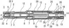
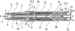
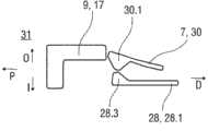
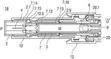
图1A和1B示出了在使用前的状态下自动注射装置的不同截平面中的两个纵截面,Figures 1A and 1B show two longitudinal sections in different sectional planes of the automatic injection device in the state before use,
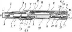
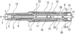
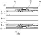
图2A和2B示出了在移除盖和针头保护套管之后的自动注射装置的两个纵截面,Figures 2A and 2B show two longitudinal sections of the automatic injection device after removal of the cap and the protective needle sleeve,
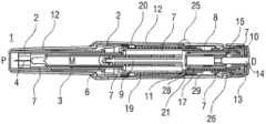
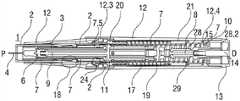
图3A和3B示出了近端被压靠注射部位的自动注射装置的两个纵截面,Figures 3A and 3B show two longitudinal sections of the automatic injection device with the proximal end pressed against the injection site,
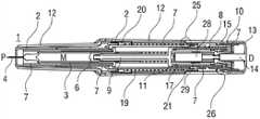
图4A和4B示出了触发按钮被压下的自动注射装置的两个纵截面,Figures 4A and 4B show two longitudinal sections of the automatic injection device with the trigger button depressed,
图5A和5B示出了在针头插入注射部位期间的自动注射装置的两个纵截面,Figures 5A and 5B show two longitudinal sections of the automatic injection device during insertion of the needle into the injection site,
图6A和6B示出了针头被完全地插入的自动注射装置的两个纵截面,Figures 6A and 6B show two longitudinal sections of the automatic injection device with the needle fully inserted,
图7A和7B示出了在注射接近剂量终了时的自动注射装置的两个纵截面,Figures 7A and 7B show two longitudinal sections of the automatic injection device when the injection is near the end of the dose,
图8A和8B示出了在剂量终了时的自动注射装置的两个纵截面,Figures 8A and 8B show two longitudinal sections of the automatic injection device at the end of the dose,
图9A和9B示出了被从注射部位移去的自动注射装置的两个纵截面,Figures 9A and 9B show two longitudinal sections of the automatic injection device being removed from the injection site,
图10A和10B示出了针头退回到针头安全位置的自动注射装置的两个纵截面,Figures 10A and 10B show two longitudinal sections of the automatic injection device with the needle retracted to the needle safety position,
图11A-11D以四个不同状态示出了自动注射装置的用于控制承载件相对于机架的移动的制动机构的示意图,Figures 11A-11D show schematic views of the braking mechanism of the automatic injection device for controlling the movement of the carrier relative to the frame in four different states,
图12A-12F以六个不同状态示出了用于控制第一套环的移动的针头插入控制机构的示意图,12A-12F show schematic diagrams of a needle insertion control mechanism for controlling movement of the first collar in six different states,
图13A-13C以三个不同状态示出了注射器退回控制机构的示意图Figures 13A-13C show schematic diagrams of the syringe retraction control mechanism in three different states
图14A-14C以三个不同状态示出了以听觉方式指示注射结束的噪声释放机构的示意图,Figures 14A-14C show schematic diagrams of the noise release mechanism audibly indicating the end of an injection in three different states,
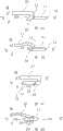
图15A-15C以三个不同状态示出了柱塞释放机构的示意图,Figures 15A-15C show schematic views of the plunger release mechanism in three different states,
图16A-16C以三个不同状态示出了按钮释放机构的示意图,Figures 16A-16C show schematic views of the button release mechanism in three different states,
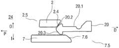
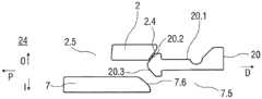
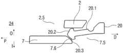
图17是柱塞释放机构的替代实施例的等轴测图,Figure 17 is an isometric view of an alternate embodiment of the plunger release mechanism,
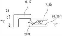
图18是按钮释放机构的替代实施例的纵截面,Figure 18 is a longitudinal section of an alternative embodiment of a button release mechanism,
图19A和19B示出了制动机构的替代实施例的纵截面,Figures 19A and 19B show a longitudinal section of an alternative embodiment of a braking mechanism,
图20是制动机构的第三实施例的纵截面,Figure 20 is a longitudinal section of a third embodiment of the braking mechanism,
图21是噪声释放机构的替代实施例的纵截面,Figure 21 is a longitudinal section of an alternative embodiment of a noise release mechanism,
图22A和22B示出了针头插入控制机构的替代实施例的纵截面,其还布置成在针头退回和针头插入时执行制动机构的功能,Figures 22A and 22B show a longitudinal section of an alternative embodiment of a needle insertion control mechanism, which is also arranged to perform the function of a braking mechanism upon needle withdrawal and needle insertion,
图23是图22的针头插入控制机构的等轴测图,Figure 23 is an isometric view of the needle insertion control mechanism of Figure 22,
图24A和24B示出了针头插入控制机构的第三实施例的纵截面,其还布置成执行制动机构的功能,Figures 24A and 24B show a longitudinal section of a third embodiment of a needle insertion control mechanism, which is also arranged to perform the function of a braking mechanism,
图25是图24的针头插入控制机构的等轴测图,Figure 25 is an isometric view of the needle insertion control mechanism of Figure 24,
图26A和26B示出了噪声释放机构的第三实施例的纵截面,并且Figures 26A and 26B show a longitudinal section of a third embodiment of the noise release mechanism, and
图27A和27B是自动注射装置的另一实施例,该自动注射装置具有代替触发按钮的包裹式套筒触发器。27A and 27B are another embodiment of an automatic injection device having a wraparound sleeve trigger instead of a trigger button.
在全部附图中,对应部分用同样的附图标记标示。Corresponding parts are marked with the same reference numerals throughout the figures.
具体实施方式Detailed ways
本说明书中的术语“斜面接合”是这样两个部件之间的接合:所述两个部件中的至少一个部件具有与另一部件接合的斜面,以便在两个部件在轴向上被推靠于彼此时该两个部件之一向旁边挠曲,这里假设此部件未被阻止向旁边挠曲。The term "slope joint" in this specification is a joint between two parts at least one of which has a slope that engages the other so that when the two parts are pushed against each other in the axial direction One of the two parts deflects sideways when in contact with each other, assuming that this part is not prevented from deflecting sideways.
图1A和1B以不同的截面示出了自动注射装置1的两个纵截面,该不同的截面相对于彼此旋转近似90°,其中自动注射装置1在注射开始之前的起始状态。自动注射装置1包括机架2。在下文中,机架2一般地被认为是位置固定的,因此其它部件的运动均是相对于机架2说明。带有中空的注射针头4的注射器3,例如Hypak注射器,被布置在自动注射装置1的近侧的部分上。当组装自动注射装置1或者注射器3时,针头保护套管5被附接到针头4。封堵器6被布置用于在远侧密封注射器3并且用于将液体药剂M通过中空的针头4排出。注射器3被保持在管状承载件7中,并且在其近端处被支撑在其中。承载件7可滑动地布置机架2中。1A and 1B show two longitudinal sections of the
压缩弹簧形式的驱动弹簧8被布置在承载件7的远侧部分中。柱塞9用于将驱动弹簧8的力传送到封堵器6。A
驱动弹簧8位于承载件7的承载件远端面10和在远端方向上布置在柱塞9上的止推面11之间。The
承载件7是关键性元件,其容纳注射器3、驱动弹簧8和柱塞9,这些都是从注射器3喷射药剂M所需要的部件。这些部件因此能够称为驱动子组件。The
机架2和承载件7布置在管状机壳12内。触发按钮13布置在机壳12的远端处。在柱塞释放机构27中,栓14从触发按钮13的远端面在始自承载件远端面10的两个弹性臂15之间在近端方向上伸出,从而在图15A所示的起始状态中阻止它们朝彼此挠曲。在图15A中,仅示出了弹性臂15之一以例示出原理。向外地,弹性臂15被捕获在远端柱塞套筒17中的相应第一凹部16中,远端柱塞套筒17在远端方向上连接到止推面11并且布置在驱动弹簧8内。弹性臂15接合在第一凹部16中,这阻止了柱塞9相对于承载件7的轴向平移。弹性臂15形成带斜面,以使它们在柱塞9和承载件7之间受驱动弹簧8加载而相对运动时向内挠曲,这在起始状态A中被栓14阻止。The
承载件7被锁定到机架2,用于通过制动机构18阻止相对平移,制动机构18在图11A至11D更详细地示出。The
触发按钮13起始通过按钮释放机构26接合到机壳12,并且不能被压下。按钮释放机构26在图16A至16C中详细示出。现在参考图16A,按钮释放机构26包括位于触发按钮13上的弹性近侧梁13.1,近侧梁13.1具有向外的第一斜面13.2和向内的第二斜面13.3。在图16A所示的起始状态中,向外的第一斜面13.2接合在带斜面的第一机壳挚子12.1中,以阻止触发按钮13移出远端D。触发按钮13在近端方向上抵靠机壳12和承载件7两者,因此被阻止在近端方向P上压下。The
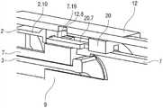
再次参考图1A和1B,呈另一压缩弹簧的形状的控制弹簧19围绕承载件7布置并且作用在近侧第一套环20和远侧第二套环21之间。控制弹簧19用以使承载件7且由此使驱动子组件在近端方向P上移动用于针头插入,或者在远端方向D上移动用于针头退回。Referring again to FIGS. 1A and 1B , a
在如图1A和1B所示展示的状态中,盖22被附接到机壳12的近端,并且针头保护套管5仍位于针头4和针头毂上方的位置。盖22的内套筒22.1布置在机架2内侧及针头保护套管5上方。在内套筒22.1中附接有倒钩23。倒钩23接合到针头保护套管5用于联合轴向平移。In the state presented as shown in Figures 1A and IB, the
自动注射装置1的操作顺序如下:The sequence of operation of the
使用者从机壳12的近端拉拔盖22。倒钩23将针头保护套管5连结到盖22。因此,在移除盖22时,针头保护套管5同样被移去。图2a和2b示出了其中盖22和针头套管5被移去的自动注射装置1。承载件7和注射器3被处于如图11A中的状态A下的制动机构18阻止在近端方向P上移动。现在参考图11A,制动机构18包括在机架2上的弹性梁2.1,梁2.1带有向内突出的第一梁头2.2。第一梁头2.2具有近侧第三斜面2.3。制动机构18进一步包括在承载件7上的长斜方形的斜面构件7.1,斜面构件7.1具有近侧第四斜面7.2和远侧第五斜面7.3。在状态A下,第一梁头2.2的倒圆的远侧在远端方向D上邻接斜面构件7.1,从而抵抗承载件7相对于机架2在近端方向P上的移动。机壳12上的肋被设置用于阻止弹性梁2.1的向外偏转,因此同样阻止承载件7相对于机架2的运动。The user pulls the
再次参考图2A和2B,使用者抓取机壳12并且将在近端P从机壳12突出的机架2置成靠着注射部位,例如靠着患者皮肤。因为自动注射装置1被压靠注射部位,所以机壳12相对于机架2在近端方向P上平移到推进位置,如图3A和3B所示。第二套环21被锁定至机壳12并且随机壳12相对于机架2且相对于自动注射装置1的几乎所有其它部件移动,由此将控制弹簧19略压靠于第一套环20,而第一套环20因针头插入控制机构24处于图12A中详细示出的状态A而被阻止在近端方向P上移动。现在参考图12A,呈箭头20.1形状的弹性构件在近端方向上布置在第一套环20上。带有箭头20.1的第一套环20在被压缩控制弹簧19的载荷下受到在近端方向P上的力。箭头20.1上的向外的第六斜面20.2与机架2上的第二远侧第七斜面2.4相互作用,机架2在向内方向I上以斜面作用于箭头20.1并且被向内抵靠承载件7的箭头20.1阻止。因此,第一套环20不能在近端方向P上平移。Referring again to Figures 2A and 2B, the user grasps the
再次参考图3A和3B,由于注射器退回控制机构25正处于图13A中详细示出的状态A下,所以第二套环21被锁定到机壳。现在参考图13A,注射器退回控制机构25包括在第二套环21上的弹性近侧梁21.1,近侧梁21.1具有有着向内凸起部21.3和远侧向外第八斜面21.4的第二梁头21.2。在第二套环21处在控制弹簧19在远端方向D上的载荷作用下时,远侧向外第八斜面21.4以在向内方向I上斜面接合第二梁头21.2的方式接合在带斜面的第二机壳挚子12.2中,这被向内抵靠承载件7的向内凸起部21.3阻止。Referring again to Figures 3A and 3B, since the syringe
再次参考图3A和3B,如果使用者要使机壳12移动离开注射部位,则控制弹簧19扩展,使自动注射装置1返回到如图2A和2B中所示的移去盖22之后的起始状态。Referring again to FIGS. 3A and 3B, if the user is to move the
在图3A和3B中的状态下,承载件7继续被制动机构18阻止在近端方向P上移动,然而,在机壳12处于其推进位置时,由于机壳12上的肋也已经移动并且不再阻止弹性梁2.1的向外偏转,所以制动机构18被解锁。机壳12相对于被制动机构18锁定到机架2的承载件7的移动导致按钮释放机构26切换到图16B所示的状态B,触发按钮13因其抵靠承载件7而不能与机壳12一起在近端方向P上平移。第一机壳挚子12.1上的斜面于触发按钮13上的近侧梁13.1上的向外第一斜面13.2相互作用,使近侧梁13.1在向内方向I上偏转,由此使近侧梁13.1上的向内第二斜面13.3接合在布置于承载件7中的带斜面的承载件挚子7.4中。随着机壳12在近端方向P上进一步平移,其向外支撑近侧梁13.1,由此将触发按钮13锁定到承载件7。触发按钮13现在从机架12的远端D伸出并且预备好被按压。In the state in Figures 3A and 3B, the
在图3A和3B中的状态下,使用者在近端方向P上压下触发按钮13。因为触发按钮13抵靠承载件7,承载件7被在近端方向P上推靠于机架2,所以承载件7和机架2在制动机构18中相互作用。使用者施加的按压触发按钮13的力通过机架2被分解到注射部位上,而不是在触发按钮13和机壳12之间。制动机构18在使用者推动触发按钮13时提供阻力。一旦使用者施加超过预定值的力,则制动机构18释放,从而开始注射周期。现在参考示出了处于状态B的制动机构18的图11B,机架2上的弹性梁2.1在承载件7上的长斜方形斜面构件7.1的加载下开始弯曲,从而储存弹性能。尽管带斜面构件7.1上的近侧第四斜面7.2,但第一梁头2.2的接触面和近侧第四斜面7.2之间摩擦的阻止第一梁头2.2在向外方向O上的移动,直到弹性变形的梁2.1的挺直力足够大而克服该摩擦。此时,弹性梁2.1在向外方向O上偏转而不阻碍承载件7,由此允许承载件7在近端方向P上平移。当承载件7在近端方向P上行进的足够远时,承载件7上的长斜方形斜面构件7.1在第一梁头2.2下通过,由此允许其松弛并且在向内方向I上后退以在远端方向上位于长斜方形斜面构件7.1之后,处于图11C中所示的状态C,同时约束承载件7相对于机架2在远端方向D上的平移。In the state in FIGS. 3A and 3B , the user depresses the
一旦所述承载件7相对于第一套环20在近端方向P上滑动得足够远,则针头插入控制机构24切换到状态B,如图12B中所示。在图12B中,承载件7已在近端方向P上平移,以使第一套环20上的箭头20.1不再被向内支撑。这可以通过承载件7中的第二凹部7.5实现。现在,箭头20.1在控制弹簧19的载荷下在向内方向I上偏转到第二凹部7.5中,实现图12C中所示的状态C。现在,第一套环20脱离机架2。作为替代,箭头20.1通过向内第九斜面20.3将第一套环20联接到承载件7,向内第九斜面20.3在第二凹部7.5的近端处接合承载件7上的远侧第十斜面7.6。因此,控制弹簧19使承载件7由此点在近端方向P上继续移动。当使用者使针头4推进其行程的一部分时,控制弹簧19在针头4伸出近端P以前接管插入。因此,使用者体验到按压按钮,而非手动地插入针头。Once the
制动机构18需要使用者施加力而非施加位移。一旦施加的力超过切换挚子所需的力,则使用者将充分地推动触发按钮13,从而确保第一套环20总是会切换。如果使用者未能通过挚子,则触发按钮13返回到其预备好被使用的非使用状态,如图3A和3B所示。该特征避免了自动注射装置1进入不确定状态。The
图4A和4B示出了自动注射装置1,其中触发按钮13被充分压下以使控制弹簧19联接到承载件7上并且使承载件7继续向前移动,但仍未抵靠机壳12。4A and 4B show the
联接到第一套环20的承载件7由控制弹簧19驱动在近端方向P上平移。因为注射器3被布置为与承载件7联合轴向平移,注射器3和针头4也被平移,导致针头4从近端P突出并且插入注射部位。触发按钮13返回其相对于机壳12的起始位置,并且从承载件7闩锁回机壳12,如图16A中的状态A。承载件7在近端方向P上进一步平移从而阻止近侧梁13.1向内偏转,因此向外第一斜面13.2不能从第一机壳挚子12.1脱离。The
在针头4即将到达全插入深度之前,如图5A和5B所示,触发按钮13上的栓14被完全地从承载件7上的弹性臂15之间拉出。因此,柱塞释放机构27到达图15B中所示的状态B,弹性臂15不再由栓14向内支撑。由于弹性臂15在第一凹部16中的斜面接合,它们在驱动弹簧8的载荷作用下在向内方向I上偏转,实现图15C中所示的状态B。因此,柱塞9被从承载件7释放并且由驱动弹簧8在近端方向P上驱动,准备注射药剂M。用以将栓14从弹性臂15之间拉出的力由控制弹簧19提供,而使弹性臂15偏转以脱离与柱塞9的接合所要求的力由驱动弹簧8提供。Immediately before the
在柱塞9移动并且闭合与封堵器6之间的间隙的情况下,承载件7在近端方向P上的移动通过推动第一套环20的控制弹簧19完成。随着承载件7在针头插入期间相对于机架2移动,针头插入机构24到达图12D中所示的状态D。箭头20.1已经随承载件7移动并且仍保持被机架2向内偏转,由此阻止第一套环20脱离承载件7。箭头20.1必须能在向外方向O上偏转以允许退回,这将在下面讨论。为了允许向外偏转,箭头20.1在近端方向上行进超过机架2的在图12A至12F中所示的紧接于机架2中的孔2.5的部分。然而,只要机壳12在控制弹簧19的载荷作用下正被保持压靠注射部位并且不许在远端方向D上返回超过预定距离,则箭头20.1将不会在其用于针头插入的运动的大约第二半程期间被机壳12上的第一肋12.3(图12A至12F未示出,见图5A至8A)在向外方向O上偏转。With the
针头4现在充分地插入注射部位,如图6A和6B所示。触发按钮13被按压和针头4充分地插入之间的时间是非常短的,然而在此时间中发生多个机械操作。针头插入深度由承载件7相对于机架2限定而非相对于机壳12限定,因此如果使用者退缩或者未能将自动注射装置1牢固地保持靠着皮肤,则仅机壳12将在远端方向D上移动,而注射深度保持恒定。The
一旦柱塞9在驱动弹簧8的力的作用下已经闭合相对于封堵器6的间隙,则封堵器6在注射器3中在近端方向P上被推动,从而将药剂M通过针头4排出到注射部位内。Once the
在注射即将结束且封堵器6已经在注射器3中几乎降至最底部之前,如图7A和7B所示,噪声部件28被释放。容差最显著地由于注射器3引起,容差的叠加要求噪声必须总是在注射结束之前释放。否则,由于部件的某些组合,噪声不会总是释放。噪声部件28包括:伸长部28.1,其布置在远端柱塞套筒17内;和远端板28.2,其布置在承载件端面10和触发按钮13的端面之间。两个第二弹性臂30从承载件远端面10开始并且在近端方向P上延伸。噪声弹簧29布置成通过在近端方向上支承于第二弹性臂30上的肋上并且在远端方向上支承于噪声部件28(未示出)上,将噪声部件28相对于承载件7在远端方向D上偏压。Immediately before the end of the injection and before the
注意:为清楚起见,图16A、B和C中未示出噪声部件28,因为它并不影响按钮释放机构26的功能。用于释放噪声部件28的噪声释放机构31在图14A、14B和14C中被示意性地示出。现在参考图14A,噪声释放机构31包括第二弹性臂30。带斜面的向内凸起部30.1布置在每一第二弹性臂30上,第二弹性臂30接合到位于噪声部件28的伸长部28.1上的相应的向外第十一斜面28.3,以便第二弹性臂30在噪声弹簧29的载荷作用下在向外方向O上偏转。在噪声释放机构31的起始状态A中,第二弹性臂30因远端柱塞套筒17的向外支撑被阻止向外偏转,由此阻止噪声部件28相对于承载件7平移。直到注射即将结束且封堵器6已经在注射器3中几乎降至最底部之前,噪声释放机构31保持在状态A,如图7A和7B所示。此时,柱塞9已相对于承载件7在近端方向P上被平移使得第二弹性臂30不再由远端柱塞套筒17支撑。噪声释放机构31由此已经到达图14B中所示的状态B。在图14C所示的状态C下,由于在带斜面的向内凸起部30.1和向外第十一斜面28.3之间的斜面接合,第二弹性臂30在噪声弹簧29的载荷作用下向外偏转,由此使噪声部件28从承载件7脱离并且允许噪声部件28由噪声弹簧29驱动在远端方向D上移动。因此,噪声部件28在远端方向D上被加速,并且远端板28.2冲击触发按钮13的内侧,从而向使用者产生指示注射要结束的听觉和触觉反馈。NOTE: For clarity, the
图8A和8B示出了自动注射装置1,其中封堵器6已经在注射器3中完全降至最底部。Figures 8A and 8B show the
如上所述,使用者能够使机壳12在控制弹簧19的力的作用下在远端方向D上移动若干毫米,而不影响针头4的位置,只要该运动低于预定距离。如果使用者希望终止注射,则任何时候它们必须允许机壳12在远端方向D上移动超过该距离。图9A和9B示出了从注射部位提升的自动注射装置1,其中机壳12一直在远端方向D上移动以便机架2从机壳12的近端伸出。随着机壳12移动,第一套环20释放承载件7,并且然后第二套环21从机壳12释放并且在远端方向D上拉承载件7。该切换的顺序是关键的,因为如果两个套环2020、21同时附接到承载件7,则退回将失败。这通过如下方式克服:通过机壳12的显著位移将套环20、21的切换间隔开。As mentioned above, the user is able to move the
第一套环20的切换在图12E和F中示出。在图12E中,在自动注射装置1从注射部位移去期间,机壳12已被允许在控制弹簧19的载荷作用下在远端方向D上移动。第一肋12.3(未示出,参见图9A)被从箭头20.1后方向外地移去。第一套环20仍被控制弹簧19在近端方向P上推动。由于箭头20.1上的向内第九斜面20.3接合承载件7上的远侧第十斜面7.6,箭头20.1在向外方向O上偏转到机架2的孔2.5(在图12A至12F中示出)中,针头插入控制机构24到达如图12E中所示的状态E,将第一套环20从承载件7脱离并将其闩锁到机架2。Switching of the
随着机壳12在从注射部位移去时进一步在远端方向D上移动,注射器退回控制机构25从其状态A(参见图13A)切换到图13B中所示的状态B。机壳12和被锁定到机壳12的第二套环21在远端方向D上一起移动,而承载件7由制动机构18以其如上所述的状态C(参见图11C)被保持在位。由于该运动,第二套环21上的近侧梁21.1的第二梁头21.2上的向内凸起部21.3不再向内邻接承载件7。作为替代,由于在控制弹簧19的载荷作用下第二梁头21.1与带斜面的第二机壳挚子12.2斜面接合,向内凸起部21.3在向内方向I上偏转到承载件7中的第三凹部7.7中。注射器退回控制机构25由此到达如图13C中所示的状态C,其中第二套环21从机壳12分离并联接到承载件7。在注射器退回控制机构25切换到状态C之前,制动机构18对承载件7的移动施加小的阻滞力,原因在于,当针头插入控制机构24已经切换到状态E时,在机壳12在远端方向D上平移时存在由第二套环21施加的在远端方向D上拉承载件7的小的滑动力。如果承载件7在第二套环21切换以前在远端方向D上移动太远,则机壳12在向内凸起部21.3能够偏转到第三凹部7.7之前走完行程从而阻止退回。As the
从制动机构18的位置C开始(参见图11C),承载件7且因此长斜方形斜面构件7.1在控制弹簧19的载荷作用下在远端方向D上平移。因此,长斜方形斜面构件7.1的远侧第五斜面7.3接合弹性梁2.1的第一梁头2.2上的近侧第三斜面2.3,以使弹性梁2.1在向内方向I上偏转。这对承载件7的移动施加小的阻滞力,这是确保第二套环21切换到承载件7所要求的。在图11D所示的状态D下,一旦第一梁头2.2完全地向内离开斜面构件7.1,则弹性梁2.1和长斜方形斜面构件7.1侧向地偏移以允许弹性梁2.1通过而不接触长斜方形斜面构件7.1。Starting from position C of the detent mechanism 18 (see FIG. 11C ), the
通过第一套环20抵靠机架2,控制弹簧19在其近端处支承在机壳中。控制弹簧19的远端D使第二套环21在远端方向D上移动,由此使承载件7且因此使注射器3与针头4克服制动机构18,如图11D所示。注意到,与带有针头保护罩的自动注射装置相反,一旦使用者允许机壳12平移得足够远,则针头4由自动注射装置1退出皮肤,而带有针头保护罩的自动注射装置需要使用者将自动注射装置从注射部位除去,由此需要他们自己将针头从皮肤抽出以允许针头保护罩推进。The
由于允许的噪声部件28的移动相对于承载件7受到限制,其不再与触发按钮13接触,在从注射部位移去时,触发按钮13已随机壳12在远端方向D上移动。当退回开始时,噪声弹簧29并不提供任何的阻滞力。一旦在承载件7退回时噪声部件28再次碰撞触发按钮13,噪声弹簧29必须被再压缩从而减少驱动退回的最后部分的力。为了即使在该减少的力的情况下确保可靠的退回,控制弹簧19必须适当地定尺寸。Since the allowed movement of the
当远侧套环21接触机壳12上的第一止回部12.4时,退回结束,如图10A和10B所示。第一套环20上的箭头20.1在图12F所示的状态F下由承载件7向内支撑,并且由此被阻止在向内方向I上偏转。箭头20.1的向外第六斜面20.2接合在机壳12上的第一肋12.3后方,从而阻止机壳12再次在近端方向P上被推动。在箭头20.1和第一肋12.3之间可设有空隙,以允许容差。Retraction ends when the
制动机构18返回到图11A中的状态A,从而将承载件7相对于机架2锁定在位,如其起始的那样,但是现在其不能被解锁,因为机壳12不能相对于机架2移动。The
第一套环20上的突部20.4现在通过机壳12上的指示窗32可见——指示自动注射装置1已被使用。The protrusion 20.4 on the
图17是柱塞释放机构27的替代实施例的等轴测图。柱塞释放机构27阻止柱塞9相对于承载件7在近端方向P上移动,直到承载件7在近端方向P上移动用于针头插入。与图15中的柱塞释放机构27相反,其中承载件7和触发按钮13的相对移动用来触发柱塞9的释放,图17中的替代实施例通过承载件7相对于第二套环21的移动释放柱塞9。图17示出了柱塞释放之前的柱塞释放机构27。第二套环21被示出为透明的以提高清晰度。柱塞9由驱动弹簧8在近端方向P上推动。为了使柱塞9推进,其必须围绕承载件7上的第十二斜面7.8旋转。柱塞9上的斜面构件9.1布置成接合该第十二斜面7.8。斜面构件9.1的旋转由第二套环21上的向内纵肋21.5阻挡,该向内纵肋21.5键接在承载件7中的纵向孔7.9中。机壳12和第二套环21保持在同一位置,即彼此相联用于联合轴向平移。在触发按钮13压下时,作为驱动子组件的一部分的承载件13和柱塞9在近端方向P上移动,首先通过使用者按压触发按钮13,然后通过控制弹簧19如上所述经由第一套环20实现接管。一旦承载件7相对于第二套环21在近端方向P上移动得足够远,则由于套环9上的斜面构件9.1在驱动弹簧8的载荷作用下与第十二斜面7.8的斜面接合,所以斜面构件9.1离开第二套环21上的纵肋21.5并且能够旋转经过纵肋21.5的近端。因此,驱动弹簧8在近端方向P上推进柱塞9用于注射药剂M。FIG. 17 is an isometric view of an alternate embodiment of the
图18是按钮释放机构26的替代实施例的纵截面。除图16的按钮释放机构26以外,其中该按钮释放机构26通过切换触发按钮13在承载件7和机壳12之间的支承而在皮肤接触时使触发按钮13出现。一旦机架2接触皮肤时承载件7已经在远端方向D上移动,则可以压下触发按钮13并且致动自动注射装置1。这确保有序的操作。FIG. 18 is a longitudinal section of an alternative embodiment of the
在图18的实施例中,触发按钮13具有两个近侧梁13.1,它们中的每一个近侧梁13.1均具有带斜面的向外凸起部13.4。在图18所示的起始状态中,带斜面的向外凸起部13.4接合在机壳12的相应的第四凹部12.5中。承载件7阻止带斜面的向外凸起部13.4从第四凹部12.5脱离,其中承载件7在内部支撑近侧梁13.1以便阻止近侧梁13.1向内偏转。近侧梁13.1上的向内凸部13.5抵靠承载件7上的第二肋7.10,以便阻止承载件7在起始状态中在近端方向P上进一步移动。一旦在机架2接触皮肤时承载件7已经在远端方向D上移动,则承载件7中的第一窗口7.11移动到向内凸部13.5后方,以允许近侧梁13.1由于它们在触发按钮13压下时斜面接合在第四凹部12.5中而向内偏转。近侧梁13.1现在由机壳12在外部支撑,并且保持接合到承载件7,即使在针头4退回时也是如此。因此,触发按钮13并不返回其起始位置,以指示自动注射装置1已被使用。In the embodiment of Figure 18, the
图18中示出的按钮释放机构26可以优选地与图17所示的柱塞释放机构27组合。The
图19A和19B示出了制动机构18的替代实施例的两个纵截面。图11A至11D的制动机构18因绕长斜方形斜面构件7.1行进的第一梁头2.2而可以称为“跑道”机构,该制动机构18具有控制承载件7相对于机架2移动的多重功能。图19A和19B中的替代制动机构18使用三个夹子7.12、7.13、2.6来产生同样的效果。19A and 19B show two longitudinal sections of an alternative embodiment of the
第一夹子7.12布置为承载件7上的向外偏压的弹性梁并且从承载件7在近端方向P上延伸。第一夹子7.12布置成阻止承载件7在机架2被压下之前、说得更准确些在机壳12在接触皮肤时平移之前,在近端方向P上移动。第一夹子7.12由并排的两个部段组成。第一部段7.14通过将机架2抵靠在凹部中来阻止承载件7在近端方向P上移动。第二部段7.15布置为向外突出的夹子头,该向外突出的夹子头被布置成被机架12上的斜面特征12.6向内斜面接合用于释放第一夹子7.12,由此在机壳12在接触皮肤时正在近端方向P上平移时,将承载件7从机架2解锁。机架2中的纵向槽2.7布置为允许第二部段7.15在锁定被释放时马上在近端方向P上滑动。在第一夹子7.12和机架2之间的轻微摩擦力提供了保证退回需要的阻滞力。The
第二夹子7.13布置为承载件7上的、在远端方向D上延伸的弹性梁,该弹性梁具有向外突出的第三梁头7.16,第三梁头7.16带有近侧斜面。第三梁头7.16用作止回部,该止回部靠着机架2上的第三肋2.9用于阻止承载件7从其起始位置在远端方向D上移动。在该位置中,承载件7和机架2在注射器3插入承载件7之前与第二夹子7.13组装,这通过第三梁头7.16.上的近侧斜面来辅助。注射器3通过防止向内偏转由此形成固定止动部来将夹子锁定在位。The second clip 7.13 is arranged as a spring beam on the
第三夹子2.6是在远端方向D上延伸的、位于机架2上的弹性梁。第三夹子2.6上的带斜面的第四梁头布置成向内接合在承载件7中的第五凹部7.17中。一旦第一夹子7.12解锁,则使用者能够通过触发按钮13压下时在近端方向P上按压承载件7来对第三夹子2.6加载。第三夹子2.6被受压加载,那就是说它将由于其与承载件7的斜面接合而向外弯曲并且突然地释放,从而提供与图11B中所示的相类似的挚子功能性。The third clip 2.6 is an elastic beam on the
图20是制动机构18的第三实施例的纵截面,所述第三实施例是图19A和19B的实施例的变形。在该实施例中,第三夹子2.6的挚子功能已被增加到第一夹子7.12中。机壳12和承载件7之间的锁定以同样的方式释放,但是挚子通过使第一夹子7.12向内偏转第二程度来提供,所述第二程度通过使机架2不具有用于第二部段7.15的狭槽2.7实现。相反,第二部段7.15一旦被机壳12上的斜面特征12.6向内斜面接合,则在机架2和承载件7之间的轴向载荷必然进一步向内斜面接合到机架2内,从而突然释放它们的接合。FIG. 20 is a longitudinal section of a third embodiment of the
图21是噪声释放机构31的替代实施例的纵截面。与其中噪声弹簧29作用在承载件7和噪声部件28之间的图14中的噪声释放机构31相反,在图21示出的实施例中,噪声弹簧29作用在机壳12和噪声部件28之间。在针头插入期间,随着噪声部件28与承载件7一起相对于机壳12移动,噪声弹簧29被压缩。当在剂量终止之前不久噪声部件28由柱塞9释放时,噪声部件28在远端方向D上移动并且冲击触发按钮13。不同于图14中的实施例,噪声弹簧29在针头退回期间不被再压缩,因为其支承在机壳12中而非支承在承载件7中。FIG. 21 is a longitudinal section of an alternative embodiment of the
图22A和22B示出了针头插入控制机构24的替代实施例的纵截面,该针头插入控制机构24还布置成在针头退回和针头插入时执行制动机构18的挚子功能。图23示出了相应的等轴测图。第一套环20上的第四夹子20.5被布置为带有梁头的弹性梁,所述梁头具有向内近侧第十三斜面20.6以用于接合承载件7上的第四肋7.18,并且在针头插入期间以及在注射期间由机壳12在外部支撑,以便在使用之前将第一套环20保持为接合到承载件7。当在注射终了或注射中途时使用者将机壳12提升离开注射部位时,机壳12中的第六凹部12.7向外移动到第四夹子20.5之后,从而允许在承载件7由第二套环21在远端方向D上拉动时第四夹子20.5被释放。因为第四夹子20.5必须被向外斜面接合,所以需要小的力来释放第四夹子20.5,从而提供了退回挚子。Figures 22A and 22B show a longitudinal section of an alternative embodiment of a needle
机架2上的第五夹子2.10在使用之前邻接第一套环20上的块20.7,从而阻止第一套环20并且因此阻止接合到第一套环20的承载件7在近端方向P上移动。为了释放,第五夹子2.10必须向外偏转并且越过块20.7上方。第五夹子2.10的向外偏转起始由机壳12阻止。一旦机壳12已经在皮肤接触时移动,机壳12中的第二窗口12.8从第五夹子2.10向外露出,从而允许向外偏转。然后在承载件7在按钮压下时被在近端方向P上推动时,第五夹子2.10被承载件7上的第十四斜面7.19偏转,因为第四夹子20.5允许承载件7相对于第一套环20在近端方向P上平移,但反过来不允许。用于针头插入的挚子以如下方式提供:在第五夹子2.10由控制弹簧19加载时,必须使第五夹子2.10偏转。A fifth clip 2.10 on the
图24A和24B示出了针头插入控制机构24的第三实施例的纵截面,该针头插入控制机构24还布置成执行制动机构18的功能,图25是图24的针头插入控制机构24的等轴测图。该实施例类似于图22A、22B和23中所示的实施例。差异在于,第五夹子2.10布置在第一套环20上,并且块20.7布置在机架2上,那就是说,它们的位置已被切换,因此在第一套环20上存在两个夹子2.10和20.5。24A and 24B show a longitudinal section of a third embodiment of the needle
第四夹子20.5和图22B中的第四夹子一致。其在针头退回被触发之前将第一套环保持为连接到承载件7,从而确保在从皮肤去除自动注射装置1而启动退回周期之前达到并维持完全的注射深度。The fourth clip 20.5 is identical to the fourth clip in Fig. 22B. It keeps the first collar connected to the
第五夹子2.10提供了用于针头插入的挚子并且将第一套环20从机架2释放,启动针头插入。第五夹子2.10邻接机架2上的块20.7,从而在使用之前阻止第一套环20并且因此阻止接合到第一套环20的承载件7在近端方向P上移动。为了释放,第五夹子2.10必须向外偏转并且越过块20.7。第五夹子2.10的向外偏转起始由机壳12阻止。一旦机壳12已经在皮肤接触时移动,则机壳12中的第二窗口12.8从第五夹子2.10向外露出,从而允许向外偏转。然后在承载件7在按钮压下时被在近端方向P上推动时,第五夹子2.10由承载件7上的第十四斜面7.19偏转,因为第四夹子20.5允许承载件7相对于第一套环20在近端方向P上平移,但反过来不允许。用于针头插入的挚子以如下方式提供:在第五夹子2.10由控制弹簧19加载时,必须使第五夹子2.10偏转。The fifth clip 2.10 provides a detent for needle insertion and releases the
图26A和26B示出了噪声释放机构31的第三实施例的纵截面。该实施例的工作不需要专用的噪声弹簧。柱塞9包括近侧上带斜面的肋9.2,肋9.2布置成在剂量即将终了之前向外张开承载件7上的两个第七夹子7.21。当近侧上带斜面的肋9.2已经行进经过第七夹子7.21时,它们急速返回并且冲击柱塞9来产生声响。承载件7的管状形状有助于传送该声响。图26A示出了释放以前的噪声释放机构31。图26B示出了释放之后的噪声释放机构31。通过逐个地将第七夹子7.21升起到近侧上带斜面的肋9.2的远侧上方,承载件7上的第七夹子7.21的近侧面轴向偏移而便于装配。26A and 26B show a longitudinal section of a third embodiment of the
图27A和27B以不同的截面示出了自动注射装置1的另一实施例的纵截面,该不同的截面相对于彼此旋转近似90°,其中自动注射装置1处于注射开始之前的起始状态。自动注射装置1基本上和图1至16中的相一致。然而,不同于图1至16中的自动注射装置,该实施例中的自动注射装置1具有包裹式套筒触发器,而非触发按钮。Figures 27A and 27B show a longitudinal section of a further embodiment of the
包裹式套筒触发器12是与具有闭合的远端面12.10的机壳12相同的部件,而非图1至16中的部件。内部触发按钮13布置在套筒触发器12内的远端处。不同于图1至16,触发按钮在任何状态下13不可见并且也不从机壳12伸出。在起始状态中,在套筒触发器12的远端面12.10和内部触发按钮13之间设置有空隙33,从而允许套筒触发器12的一些行程,而不会妨碍触发按钮13。The
由于自动注射装置1在其它方面并不不同于图1至16中的自动注射装置,所以其基本上以同样的方式来操作,但存在如下差异:Since the
随着机架2被布置成靠着注射部位,套筒触发器12在套筒行程的第一阶段中相对于机架2在近端方向P上平移到推进位置,从而消除在套筒触发器12的远端面12.10和内部触发按钮13之间的空隙33。如在图1至16中的实施例中那样,这一运动使得制动机构18和触发按钮13被解锁。当使用者在套筒行程的第二阶段中继续压下套筒触发器12从而使得其在近端方向P上推进时,远端面12.10碰撞内部触发按钮13,由此将其压下,直到第一套环20从机架2释放并且控制弹簧力被耦合到承载件7。承载件7然后推进直到内部触发按钮13停止在机壳12中的另一肋上并且柱塞释放机构27被释放(注意,在该实施例中,栓14较短)。With the
从使用者视角来看,制动机构18布置成在使用者到达套筒行程的第二阶段时提供阻力。而在内部,此时与图1至16中的实施例无差异。From the user's perspective, the
使用者在套筒行程的第二阶段使套筒触发器12充分地推进,由此充分地压下内部触发按钮13并且克服制动机构,从而触发针头插入,如图1至16的实施例中一样。The user advances the
由于控制弹簧19在按钮压下时接管而充分推进承载件7用于针头插入,所以内部触发按钮13在套筒触发器12中的内部第五肋12.11上降至最底部并且内部触发按钮13切换回到被锁定至套筒触发器12,如图16C中那样。As the
图27A和27B的实施例也可与图17至26中示出的可选择特征组合。The embodiment of Figures 27A and 27B may also be combined with the optional features shown in Figures 17-26.
毫无疑问,在上述实施例中所述的两个部件之间的所带斜面接合中,可以在一个或另一部件上存在仅一个斜面,或者在两个部件上均存在斜面,而不会明显影响斜面接合的效果。It goes without saying that in a beveled joint between two parts as described in the above embodiments, there may be only one bevel on one or the other part, or both parts, without Significantly affects the effect of bevel joints.
附图标记reference sign
1 自动注射装置1 automatic injection device
2 机架2 racks
2.1 弹性梁2.1 Elastic Beam
2.2 第一梁头2.2 The first beam head
2.3 近侧第三斜面2.3 Proximal third slope
2.4 远侧第七斜面2.4 Distal seventh slope
2.5 孔2.5 holes
2.6 第三夹子2.6 The third clip
2.7 槽口2.7 Notches
2.8 第四梁头2.8 The fourth beam head
2.9 第三肋2.9 Third rib
2.10 第五夹子2.10 The fifth clip
2.11 第六夹子2.11 The sixth clip
3 注射器3 syringes
4 中空注射针头4 hollow injection needles
5 针头保护套管5 needle protection sleeve
6 封堵器6 occluder
7 承载件7 Carriers
7.1 斜面构件7.1 Inclined member
7.2 近侧第四斜面7.2 Proximal fourth slope
7.3 远侧第五斜面7.3 Distal fifth bevel
7.4 承载件掣子7.4 Carrier detent
7.5 第二凹部7.5 Second recess
7.6 远侧第十斜面7.6 Distal Tenth Bevel
7.7 第三凹部7.7 The third recess
7.8 第十二斜面7.8 Twelfth slope
7.9 纵向孔7.9 Longitudinal holes
7.10 第二肋7.10 Second rib
7.11 第一窗口7.11 First window
7.12 第一夹子7.12 First clip
7.13 第二夹子7.13 Second clip
7.14 第一部段7.14
7.15 第二部段7.15 Second section
7.16 第三梁头7.16 The third beam head
7.17 第五凹部7.17 The fifth recess
7.18 第四肋7.18 Fourth rib
7.19 第十四斜面7.19 The fourteenth slope
7.20 第十五斜面7.20 Fifteenth slope
7.21 第七夹子7.21 The seventh clip
8 驱动弹簧8 drive spring
9 柱塞9 plunger
9.1 斜面构件9.1 Inclined member
9.2 近侧上带斜面的肋9.2 Beveled ribs on the proximal side
10 承载件端面10 Carrier end face
11 止推面11 Thrust surface
12 机壳12 Chassis
12.1 第一机壳掣子12.1 First case detent
12.2 第二机壳掣子12.2 Second case detent
12.3 第一肋12.3 First rib
12.4 第一止回部12.4 The first non-return part
12.5 第四凹部12.5 The fourth recess
12.6 斜面特征12.6 Bevel features
12.7 第六凹部12.7 The sixth recess
12.8 第二窗口12.8 Second window
12.9 第三窗口12.9 The third window
12.10 远端面12.10 Distal face
12.11 第五肋12.11 Fifth rib
13 触发按钮13 trigger button
13.1 近侧梁13.1 Proximal Beam
13.2 向外第一斜面13.2 Outward first slope
13.3 向内第二斜面13.3 Second inward bevel
13.4 带斜面的向外凸起部13.4 Outward raised portion with bevel
13.5 向内凸部13.5 Inward convex part
13.6 第二止回部13.6 Second non-return part
14 栓14 bolts
15 弹性臂15 elastic arms
16 第一凹部16 first recess
17 远侧柱塞套筒17 Distal plunger sleeve
18 制动机构18 brake mechanism
19 控制弹簧19 control spring
20 第一套环20 first ring
20.1 箭头20.1 Arrows
20.2 向外第六斜面20.2 Outward sixth slope
20.3 向内第九斜面20.3 Ninth inward bevel
20.4 突部20.4 Protrusion
20.5 第四夹子20.5 Fourth clip
20.6 向内的近侧第十三斜面20.6 Inward proximal thirteenth bevel
20.7 块20.7 blocks
20.8 第五夹子20.8 Fifth clip
21 第二套环21 second collar
21.1 近侧梁21.1 Proximal Beam
21.2 第二梁头21.2 The second beam head
21.3 向内凸起部21.3 Inward raised part
21.4 远侧向外第八斜面21.4 Far-out eighth bevel
21.5 纵肋21.5 Longitudinal ribs
22 盖22 cover
22.1 内套筒22.1 Inner sleeve
23 倒钩23 barbs
24 针头插入控制机构24 needle insertion control mechanism
25 注射器退回控制机构25 Syringe return control mechanism
26 按钮释放机构26 push button release mechanism
27 柱塞释放机构27 Plunger release mechanism
28 噪声部件28 noise parts
28.1 伸长部28.1 Extension
28.2 远端板28.2 Remote board
28.3 向外第十一斜面28.3 Outward Eleventh Bevel
29 噪声弹簧29 noise spring
30 第二弹性臂30 second elastic arm
30.1 带斜面的向内凸起部30.1 Inwardly raised portion with bevel
31 噪声释放机构31 Noise release mechanism
32 指示窗32 indicator window
33 空隙33 void
D 远端,远端方向D Distal, distal direction
I 向内方向I inward direction
M 药剂M potion
O 向外方向O outward direction
P 近端,近端方向P proximal, proximal direction
Claims (14)
Translated fromChineseApplications Claiming Priority (3)
| Application Number | Priority Date | Filing Date | Title |
|---|---|---|---|
| EP11155046.3 | 2011-02-18 | ||
| EP11155046AEP2489388A1 (en) | 2011-02-18 | 2011-02-18 | Auto-injector |
| PCT/EP2012/052653WO2012110583A1 (en) | 2011-02-18 | 2012-02-16 | Auto-injector |
Publications (2)
| Publication Number | Publication Date |
|---|---|
| CN103492001Atrue CN103492001A (en) | 2014-01-01 |
| CN103492001B CN103492001B (en) | 2016-04-06 |
Family
ID=49080501
Family Applications (1)
| Application Number | Title | Priority Date | Filing Date |
|---|---|---|---|
| CN201280019032.5AActiveCN103492001B (en) | 2011-02-18 | 2012-02-16 | Automated injection device |
Country Status (12)
| Country | Link |
|---|---|
| US (2) | US9636459B2 (en) |
| EP (2) | EP2489388A1 (en) |
| JP (1) | JP5881745B2 (en) |
| CN (1) | CN103492001B (en) |
| AR (1) | AR085264A1 (en) |
| AU (1) | AU2012217087B2 (en) |
| BR (1) | BR112013020848A2 (en) |
| CA (1) | CA2826620A1 (en) |
| DK (1) | DK2675504T3 (en) |
| IL (1) | IL227806A (en) |
| TW (1) | TWI555545B (en) |
| WO (1) | WO2012110583A1 (en) |
Cited By (6)
| Publication number | Priority date | Publication date | Assignee | Title |
|---|---|---|---|---|
| CN107690339A (en)* | 2015-03-23 | 2018-02-13 | 赛诺菲-安万特德国有限公司 | Interconnection for the housing and housing parts of injection device |
| CN109641104A (en)* | 2016-08-31 | 2019-04-16 | 娜敏芮维皮利业有限责任公司 | Automatic injection device with preferred arrangement |
| CN109641110A (en)* | 2016-08-26 | 2019-04-16 | 赛诺菲-安万特德国有限公司 | audible indicator |
| CN111918686A (en)* | 2018-02-12 | 2020-11-10 | 赛诺菲 | Syringe device |
| US11253654B2 (en) | 2016-09-30 | 2022-02-22 | Owen Mumford Limited | Injection devices |
| CN116115863A (en)* | 2018-09-13 | 2023-05-16 | 欧文蒙福德有限公司 | injection device |
Families Citing this family (30)
| Publication number | Priority date | Publication date | Assignee | Title |
|---|---|---|---|---|
| EP2399635A1 (en) | 2010-06-28 | 2011-12-28 | Sanofi-Aventis Deutschland GmbH | Auto-injector |
| EP2438944A1 (en)* | 2010-10-08 | 2012-04-11 | Sanofi-Aventis Deutschland GmbH | Auto-injector |
| EP2489384A1 (en)* | 2011-02-18 | 2012-08-22 | Sanofi-Aventis Deutschland GmbH | Auto-injector |
| EP2489386A1 (en) | 2011-02-18 | 2012-08-22 | Sanofi-Aventis Deutschland GmbH | Auto-injector |
| EP2489389A1 (en) | 2011-02-18 | 2012-08-22 | Sanofi-Aventis Deutschland GmbH | Detent mechanism |
| EP2489388A1 (en) | 2011-02-18 | 2012-08-22 | Sanofi-Aventis Deutschland GmbH | Auto-injector |
| EP2489382A1 (en) | 2011-02-18 | 2012-08-22 | Sanofi-Aventis Deutschland GmbH | Auto-injector |
| EP2489381A1 (en) | 2011-02-18 | 2012-08-22 | Sanofi-Aventis Deutschland GmbH | Auto-injector |
| EP2489380A1 (en) | 2011-02-18 | 2012-08-22 | Sanofi-Aventis Deutschland GmbH | Injection device |
| EP2489387A1 (en) | 2011-02-18 | 2012-08-22 | Sanofi-Aventis Deutschland GmbH | Auto-injector |
| EP2489385A1 (en) | 2011-02-18 | 2012-08-22 | Sanofi-Aventis Deutschland GmbH | Auto-injector |
| EP2583707A1 (en)* | 2011-10-21 | 2013-04-24 | Sanofi-Aventis Deutschland GmbH | Auto-injector |
| EP2606924A1 (en) | 2011-12-21 | 2013-06-26 | Sanofi-Aventis Deutschland GmbH | Autoinjector having a retracting syringe carrier |
| RU2598809C1 (en)* | 2012-10-05 | 2016-09-27 | Кэрбей Юроп Лтд | Device for drug delivery |
| EP3590568A1 (en) | 2013-03-22 | 2020-01-08 | TecPharma Licensing AG | Substance dispensing device with a signalling device |
| EP2823841A1 (en) | 2013-07-09 | 2015-01-14 | Sanofi-Aventis Deutschland GmbH | Autoinjector |
| EP2923714A1 (en) | 2014-03-28 | 2015-09-30 | Sanofi-Aventis Deutschland GmbH | Autoinjector triggered by skin contact |
| IL295010B1 (en) | 2015-03-10 | 2025-06-01 | Regeneron Pharma | Pollution-free piercing system and method |
| HK1248625A1 (en) | 2015-06-18 | 2018-10-19 | Sanofi-Aventis Deutschland Gmbh | Cap assembly for covering a needle shield and method for assembling the cap assembly |
| WO2018167498A1 (en)* | 2017-03-15 | 2018-09-20 | Owen Mumford Limited | An injection apparatus |
| CN119950880A (en) | 2017-05-05 | 2025-05-09 | 里珍纳龙药品有限公司 | Auto-injectors and related methods of use |
| CN112188907A (en) | 2018-05-24 | 2021-01-05 | 诺华股份有限公司 | Automatic drug delivery device |
| EP3801694B1 (en) | 2018-06-08 | 2025-08-27 | Antares Pharma, Inc. | Auto-insert injector |
| CH715110A2 (en)* | 2018-06-19 | 2019-12-30 | Tecpharma Licensing Ag | Injection device for administering a medical substance, comprising a coil spring, and such a coil spring. |
| GB2577694B (en) | 2018-10-01 | 2022-06-22 | Janssen Pharmaceuticals Inc | Locking member for an injection device and an injection device trainer |
| GB2577696B (en) | 2018-10-01 | 2022-09-14 | Janssen Pharmaceuticals Inc | Latch for an injection device and an injection device trainer |
| GB2577693B (en) | 2018-10-01 | 2022-06-22 | Janssen Pharmaceuticals Inc | Reset connector for an injection device and an injection device trainer |
| CA3194862A1 (en)* | 2020-10-07 | 2022-04-14 | Christopher Stout | Auto-injector system and method |
| GB2604584B (en)* | 2021-02-28 | 2023-08-02 | Owen Mumford Ltd | Injector apparatus facilitating automatic needle withdrawal |
| USD1007676S1 (en) | 2021-11-16 | 2023-12-12 | Regeneron Pharmaceuticals, Inc. | Wearable autoinjector |
Citations (4)
| Publication number | Priority date | Publication date | Assignee | Title |
|---|---|---|---|---|
| CN1901957A (en)* | 2003-11-07 | 2007-01-24 | Shl医药公司 | Device for an injector |
| US20080051713A1 (en)* | 2004-12-31 | 2008-02-28 | Philippe Kohlbrenner | Device for the dosed administration of a fluid product comprising a torsion spring drive |
| US20100268170A1 (en)* | 2007-09-25 | 2010-10-21 | Becton Dickinson France S.A.S. | Autoinjector |
| US20100286612A1 (en)* | 2009-05-06 | 2010-11-11 | William Cirillo | Medication injection supervisor device |
Family Cites Families (74)
| Publication number | Priority date | Publication date | Assignee | Title |
|---|---|---|---|---|
| GB8926825D0 (en) | 1989-11-28 | 1990-01-17 | Glaxo Group Ltd | Device |
| US6287610B1 (en) | 1991-11-20 | 2001-09-11 | Monfort, Inc. | Method for increasing the tenderness of a meat product |
| US5681291A (en) | 1992-11-19 | 1997-10-28 | Tebro S.A. | Disposable auto-injector for prefilled syringes |
| US5320609A (en) | 1992-12-07 | 1994-06-14 | Habley Medical Technology Corporation | Automatic pharmaceutical dispensing syringe |
| EP0693946B1 (en) | 1993-03-24 | 2001-05-16 | Owen Mumford Limited | Improvements relating to injection devices |
| FR2715071B1 (en)* | 1994-01-17 | 1996-03-01 | Aguettant Lab | Automatic drug injector. |
| US5478316A (en) | 1994-02-02 | 1995-12-26 | Becton, Dickinson And Company | Automatic self-injection device |
| JP3568959B2 (en) | 1995-03-07 | 2004-09-22 | イーライ・リリー・アンド・カンパニー | Reusable dosing device |
| FR2733155B1 (en) | 1995-04-18 | 1997-09-19 | Tebro | RECHARGEABLE SELF-INJECTOR |
| US5746215A (en) | 1996-11-01 | 1998-05-05 | U.S. Medical Instruments, Inc. | IV infusion or collection device with extendable and retractable needle |
| SE9803662D0 (en) | 1998-10-26 | 1998-10-26 | Pharmacia & Upjohn Ab | autoinjector |
| FR2787246B1 (en) | 1998-12-09 | 2001-02-23 | Alpes Lasers | SEMICONDUCTOR TYPE LASER |
| EP3138598B1 (en) | 2000-08-02 | 2019-10-23 | Becton, Dickinson and Company | Pen needle and safety shield system |
| AU2001281753A1 (en) | 2000-08-29 | 2002-03-13 | Novo-Nordisk A/S | Automatic injection device with torsion function for retraction of needle |
| BR0114629A (en) | 2000-10-13 | 2004-01-20 | Alza Corp | Apparatus and method for skin piercing with microprojections |
| SE518981C2 (en) | 2000-12-14 | 2002-12-17 | Shl Medical Ab | autoinjector |
| US6461362B1 (en) | 2001-04-30 | 2002-10-08 | Mdc Investment Holdings, Inc. | Catheter insertion device with retractable needle |
| JP4339260B2 (en)* | 2002-11-25 | 2009-10-07 | テクファーマ・ライセンシング・アクチェンゲゼルシャフト | Injection device with needle protection device |
| JP2006507061A (en)* | 2002-11-25 | 2006-03-02 | テクファーマ・ライセンシング・アクチェンゲゼルシャフト | Automatic injection device with resettable release safety device |
| GB0312852D0 (en) | 2003-06-05 | 2003-07-09 | Owen Mumford Ltd | Improvements relating to syringe firing mechanisms |
| US20050027255A1 (en) | 2003-07-31 | 2005-02-03 | Sid Technologies, Llc | Automatic injector |
| DE10342059B4 (en) | 2003-09-11 | 2007-03-01 | Tecpharma Licensing Ag | Delivery device with piercing and Ausschutinrichtung |
| DE10351599A1 (en) | 2003-11-05 | 2005-06-16 | Tecpharma Licensing Ag | Auto-injection device |
| CH696421A5 (en) | 2003-12-18 | 2007-06-15 | Tecpharma Licensing Ag | Autoinjector with arresting the drug container. |
| EP1715903B1 (en)* | 2004-01-23 | 2007-10-24 | The Medical House Plc | Injection device |
| GB2410188B (en) | 2004-01-23 | 2006-01-25 | Medical House Plc | Injection device |
| US20050222539A1 (en) | 2004-03-30 | 2005-10-06 | Pediamed Pharmaceuticals, Inc. | Automatic injection device |
| US7160219B2 (en) | 2004-06-03 | 2007-01-09 | Arvinmeritor Technology Llc. | Method and apparatus for lubricating a differential gear assembly |
| US9220595B2 (en) | 2004-06-23 | 2015-12-29 | Orthovita, Inc. | Shapeable bone graft substitute and instruments for delivery thereof |
| US8048035B2 (en) | 2004-08-06 | 2011-11-01 | Meridian Medical Technologies, Inc. | Automatic injector with needle cover |
| DE102004041151A1 (en) | 2004-08-25 | 2006-03-02 | Tecpharma Licensing Ag | Dosing device with flow control |
| EP1814616A1 (en) | 2004-11-04 | 2007-08-08 | Sid Technologies Llc | Automatic injector |
| PL1877119T3 (en) | 2005-01-25 | 2019-03-29 | Novo Nordisk A/S | An injection device with an end of dose feedback mechanism |
| WO2006111862A1 (en) | 2005-04-20 | 2006-10-26 | Becton Dickinson France | Injection set and injection assistance device |
| WO2006134153A1 (en) | 2005-06-16 | 2006-12-21 | Novo Nordisk A/S | Method and apparatus for assisting patients in self administration of medication |
| US20080195056A1 (en) | 2005-06-21 | 2008-08-14 | Steven Bishop | Apparatus And Method For Injecting A Pharmaceutical |
| DE202005010389U1 (en) | 2005-07-01 | 2005-09-08 | Tecpharma Licensing Ag | Injection unit capable of accommodating an ampule incorporates a fixed magnet and a counter-magnet on the movable piston rod of the unit |
| DE102005052460A1 (en) | 2005-11-03 | 2007-05-16 | Tecpharma Licensing Ag | Autoinjector - Flow control for container change |
| FR2899482A1 (en) | 2006-04-11 | 2007-10-12 | Becton Dickinson France Soc Pa | Automatic medicament/product injection device for patient, has safety shield coupled to housing, and provided in active state at end of needle insertion step before which product/medicament injection step is not started |
| GB2437922B (en)* | 2006-05-10 | 2010-12-08 | Owen Mumford Ltd | Injection device comprising a window and a shutter element |
| FR2905273B1 (en) | 2006-09-06 | 2009-04-03 | Becton Dickinson France Soc Pa | AUTOMATIC INJECTION DEVICE WITH TIMING MEANS. |
| ES2365931T3 (en) | 2006-12-13 | 2011-10-13 | Shl Group Ab | AUTOMATIC INJECTOR |
| US20080228147A1 (en) | 2007-03-15 | 2008-09-18 | Bristol-Myers Squibb Company | Injector for use with pre-filled syringes and method of assembly |
| DE102007013836A1 (en) | 2007-03-22 | 2008-09-25 | Tecpharma Licensing Ag | Injection device with controlled needle retraction |
| DE102007013838A1 (en) | 2007-03-22 | 2008-09-25 | Tecpharma Licensing Ag | Injection device with time-constant Ausschüttsignal |
| CN101678167B (en) | 2007-03-22 | 2013-09-18 | 特克法马许可公司 | Spring Mechanisms in Injection Devices |
| EP2129415B1 (en) | 2007-03-22 | 2018-10-24 | Tecpharma Licensing AG | Injection device with controlled needle retraction |
| DE102007016811A1 (en) | 2007-04-05 | 2008-10-09 | Tecpharma Licensing Ag | Device for administering a fluid substance from a multi-chamber ampoule |
| US8057427B2 (en) | 2007-05-09 | 2011-11-15 | Meridian Medical Technologies, Inc. | Drug delivery system with a small amount of a therapeutic agent |
| DE102007030327A1 (en) | 2007-06-29 | 2009-01-02 | Tecpharma Licensing Ag | Injection device with a spring for a needle protection sleeve |
| DK2211946T3 (en)* | 2007-09-25 | 2017-11-13 | Becton Dickinson France | AUTO INJECTOR WITH POSITIONABLE TRIGGES IN ACTIVE POSITION BY MOVING A SAFETY PROTECTION AND INDICATING THE ACTIVE POSITION |
| DE602008006458D1 (en) | 2007-11-12 | 2011-06-01 | Bang & Olufsen Medicom As | AUTOMATIC INJECTOR WITH AUTOMATIC NEEDLE FEED |
| WO2009063030A1 (en) | 2007-11-14 | 2009-05-22 | Shl Group Ab | Automatic injection device with actively triggered syringe withdrawal |
| WO2009080775A1 (en) | 2007-12-20 | 2009-07-02 | Novo Nordisk A/S | Injection device for delivering a fixed dose of liquid drug |
| GB0801874D0 (en) | 2008-02-01 | 2008-03-12 | Liversidge Barry P | Injection device |
| GB2460398A (en) | 2008-05-20 | 2009-12-02 | Owen Mumford Ltd | Auto-injector having a magnetic injection indicator and a needle sheath retainer |
| CN102209566B (en) | 2008-09-29 | 2014-03-26 | 贝克顿迪金森法国公司 | Automatic injection device |
| US8979807B2 (en) | 2008-09-29 | 2015-03-17 | Becton Dickinson France | Automatic injection device with audible indicator of completed injection |
| GB2469672B (en)* | 2009-04-23 | 2013-09-25 | Medical House Ltd | Improved autoinjector |
| JP5701889B2 (en) | 2009-10-08 | 2015-04-15 | エス・ホー・エル・グループ・アクチボラゲットShl Group Ab | Drug supply device |
| US8986245B2 (en) | 2010-02-09 | 2015-03-24 | Shl Group Ab | Medicament delivery device |
| EP2583708B1 (en) | 2010-03-31 | 2023-02-22 | SHL Medical AG | Medicament delivery device comprising feedback signalling means |
| EP2399635A1 (en) | 2010-06-28 | 2011-12-28 | Sanofi-Aventis Deutschland GmbH | Auto-injector |
| GB201021767D0 (en) | 2010-12-22 | 2011-02-02 | Owen Mumford Ltd | Autoinjectors |
| EP2489385A1 (en) | 2011-02-18 | 2012-08-22 | Sanofi-Aventis Deutschland GmbH | Auto-injector |
| EP2489383A1 (en) | 2011-02-18 | 2012-08-22 | Sanofi-Aventis Deutschland GmbH | Auto-injector |
| EP2489380A1 (en) | 2011-02-18 | 2012-08-22 | Sanofi-Aventis Deutschland GmbH | Injection device |
| EP2489382A1 (en) | 2011-02-18 | 2012-08-22 | Sanofi-Aventis Deutschland GmbH | Auto-injector |
| EP2489390A1 (en) | 2011-02-18 | 2012-08-22 | Sanofi-Aventis Deutschland GmbH | Detent mechanism |
| EP2489381A1 (en) | 2011-02-18 | 2012-08-22 | Sanofi-Aventis Deutschland GmbH | Auto-injector |
| EP2489384A1 (en) | 2011-02-18 | 2012-08-22 | Sanofi-Aventis Deutschland GmbH | Auto-injector |
| EP2489388A1 (en) | 2011-02-18 | 2012-08-22 | Sanofi-Aventis Deutschland GmbH | Auto-injector |
| EP2489387A1 (en) | 2011-02-18 | 2012-08-22 | Sanofi-Aventis Deutschland GmbH | Auto-injector |
| EP2489389A1 (en) | 2011-02-18 | 2012-08-22 | Sanofi-Aventis Deutschland GmbH | Detent mechanism |
- 2011
- 2011-02-18EPEP11155046Apatent/EP2489388A1/ennot_activeCeased
- 2012
- 2012-02-16BRBR112013020848Apatent/BR112013020848A2/ennot_activeIP Right Cessation
- 2012-02-16DKDK12703839.6Tpatent/DK2675504T3/enactive
- 2012-02-16ARARP120100529Apatent/AR085264A1/ennot_activeApplication Discontinuation
- 2012-02-16AUAU2012217087Apatent/AU2012217087B2/ennot_activeCeased
- 2012-02-16EPEP12703839.6Apatent/EP2675504B1/enactiveActive
- 2012-02-16USUS13/983,811patent/US9636459B2/enactiveActive
- 2012-02-16CACA2826620Apatent/CA2826620A1/ennot_activeAbandoned
- 2012-02-16TWTW101105011Apatent/TWI555545B/ennot_activeIP Right Cessation
- 2012-02-16CNCN201280019032.5Apatent/CN103492001B/enactiveActive
- 2012-02-16WOPCT/EP2012/052653patent/WO2012110583A1/enactiveApplication Filing
- 2012-02-16JPJP2013553937Apatent/JP5881745B2/enactiveActive
- 2013
- 2013-08-05ILIL227806Apatent/IL227806A/enactiveIP Right Grant
- 2017
- 2017-03-28USUS15/471,926patent/US10384015B2/enactiveActive
Patent Citations (4)
| Publication number | Priority date | Publication date | Assignee | Title |
|---|---|---|---|---|
| CN1901957A (en)* | 2003-11-07 | 2007-01-24 | Shl医药公司 | Device for an injector |
| US20080051713A1 (en)* | 2004-12-31 | 2008-02-28 | Philippe Kohlbrenner | Device for the dosed administration of a fluid product comprising a torsion spring drive |
| US20100268170A1 (en)* | 2007-09-25 | 2010-10-21 | Becton Dickinson France S.A.S. | Autoinjector |
| US20100286612A1 (en)* | 2009-05-06 | 2010-11-11 | William Cirillo | Medication injection supervisor device |
Cited By (14)
| Publication number | Priority date | Publication date | Assignee | Title |
|---|---|---|---|---|
| CN107690339A (en)* | 2015-03-23 | 2018-02-13 | 赛诺菲-安万特德国有限公司 | Interconnection for the housing and housing parts of injection device |
| CN107690339B (en)* | 2015-03-23 | 2021-05-11 | 赛诺菲-安万特德国有限公司 | Housing for injection device and interconnection of housing parts |
| US11400218B2 (en) | 2015-03-23 | 2022-08-02 | Sanofi-Aventis Deutschland Gmbh | Housing for an injection device and interconnection of housing components |
| US12102810B2 (en) | 2016-08-26 | 2024-10-01 | Sanofi-Aventis Deutschland Gmbh | Audible indicator |
| CN109641110A (en)* | 2016-08-26 | 2019-04-16 | 赛诺菲-安万特德国有限公司 | audible indicator |
| US11369744B2 (en) | 2016-08-26 | 2022-06-28 | Sanofi-Aventis Deutschland Gmbh | Audible indicator |
| CN109641110B (en)* | 2016-08-26 | 2022-08-16 | 赛诺菲-安万特德国有限公司 | Auditory indicator |
| CN109641104A (en)* | 2016-08-31 | 2019-04-16 | 娜敏芮维皮利业有限责任公司 | Automatic injection device with preferred arrangement |
| US11253654B2 (en) | 2016-09-30 | 2022-02-22 | Owen Mumford Limited | Injection devices |
| CN111918686A (en)* | 2018-02-12 | 2020-11-10 | 赛诺菲 | Syringe device |
| US11826556B2 (en) | 2018-02-12 | 2023-11-28 | Sanofi | Injector device |
| US12171991B2 (en) | 2018-02-12 | 2024-12-24 | Sanofi | Injector device |
| CN116115863A (en)* | 2018-09-13 | 2023-05-16 | 欧文蒙福德有限公司 | injection device |
| CN116115863B (en)* | 2018-09-13 | 2024-11-26 | 欧文蒙福德有限公司 | Injection device |
Also Published As
| Publication number | Publication date |
|---|---|
| AU2012217087A1 (en) | 2013-09-05 |
| US9636459B2 (en) | 2017-05-02 |
| BR112013020848A2 (en) | 2016-10-18 |
| HK1188161A1 (en) | 2014-04-25 |
| EP2675504A1 (en) | 2013-12-25 |
| EP2489388A1 (en) | 2012-08-22 |
| AR085264A1 (en) | 2013-09-18 |
| JP2014513565A (en) | 2014-06-05 |
| US20170197036A1 (en) | 2017-07-13 |
| DK2675504T3 (en) | 2015-09-28 |
| US10384015B2 (en) | 2019-08-20 |
| TWI555545B (en) | 2016-11-01 |
| JP5881745B2 (en) | 2016-03-09 |
| US20130317428A1 (en) | 2013-11-28 |
| CN103492001B (en) | 2016-04-06 |
| AU2012217087B2 (en) | 2016-02-25 |
| CA2826620A1 (en) | 2012-08-23 |
| EP2675504B1 (en) | 2015-06-24 |
| WO2012110583A1 (en) | 2012-08-23 |
| IL227806A (en) | 2017-04-30 |
| TW201247272A (en) | 2012-12-01 |
Similar Documents
| Publication | Publication Date | Title |
|---|---|---|
| US12208248B2 (en) | Auto-injector | |
| US20230140568A1 (en) | Auto-Injector | |
| US20230082328A1 (en) | Auto-injector | |
| CN103492001B (en) | Automated injection device | |
| CN103476444B (en) | automatic injection device | |
| CN103492003B (en) | automatic injection device | |
| CN103476445B (en) | automatic injection device | |
| CN103476442B (en) | Automated injection device | |
| CN103476443B (en) | automatic injection device | |
| CN103492000B (en) | Injection device | |
| HK1188161B (en) | Auto-injector | |
| HK1188158B (en) | Auto-injector |
Legal Events
| Date | Code | Title | Description |
|---|---|---|---|
| C06 | Publication | ||
| PB01 | Publication | ||
| SE01 | Entry into force of request for substantive examination | ||
| SE01 | Entry into force of request for substantive examination | ||
| C14 | Grant of patent or utility model | ||
| GR01 | Patent grant |