CN103488076A - Smart watch strap, smart watch and assembly method of flexible circuit board antenna - Google Patents
Smart watch strap, smart watch and assembly method of flexible circuit board antennaDownload PDFInfo
- Publication number
- CN103488076A CN103488076ACN201310437010.7ACN201310437010ACN103488076ACN 103488076 ACN103488076 ACN 103488076ACN 201310437010 ACN201310437010 ACN 201310437010ACN 103488076 ACN103488076 ACN 103488076A
- Authority
- CN
- China
- Prior art keywords
- watchband
- circuit board
- antenna
- pedestal
- smart watch
- Prior art date
- Legal status (The legal status is an assumption and is not a legal conclusion. Google has not performed a legal analysis and makes no representation as to the accuracy of the status listed.)
- Pending
Links
Images


Landscapes
- Electric Clocks (AREA)
Abstract
Description
Translated fromChinese技术领域technical field
本发明涉及可穿戴设备领域,尤其涉及智能手表表带、智能手表及柔性电路板天线的装配方法。The invention relates to the field of wearable devices, in particular to a smart watch strap, a smart watch and an assembly method for a flexible circuit board antenna.
背景技术Background technique
随着电子元件的高度集成化和移动互联技术的高速发展,可穿戴设备受到越来越多用户的热捧。作为可穿戴设备中的重要分支,智能手表也受到了设备开发商和用户的普遍关注。With the high integration of electronic components and the rapid development of mobile Internet technology, wearable devices are favored by more and more users. As an important branch of wearable devices, smart watches have also received widespread attention from device developers and users.
智能手表是一种搭载了智能化操作系统,具备多种通讯功能和数据运算处理能力的手表形的智能移动通讯终端。智能手表不仅具有与传统手表类似的外形和体积,还具备了集成符合3G、WiFi、蓝牙等多种通讯协议的无线通讯功能,因此,需要在智能手表上设置天线来实现信号的收发。现有技术中,智能手表的天线集成在智能手表的内部。这就要求智能手表的天线在极小的空间内产生多个频段的谐振,完成在不同频段上信号的发送和接收。而且,智能手表内一般还需要集成中央处理器、存储器、显示驱动电路等其他电路模块。这使得智能手表内电信号的传输和处理相对集中,从而会有较大的干扰,在如此强干扰的环境下完成准确的信号发送和接收变得十分困难。A smart watch is a watch-shaped smart mobile communication terminal that is equipped with an intelligent operating system and has a variety of communication functions and data processing capabilities. Smart watches not only have a shape and volume similar to traditional watches, but also have integrated wireless communication functions that conform to various communication protocols such as 3G, WiFi, and Bluetooth. Therefore, it is necessary to set an antenna on the smart watch to realize signal transmission and reception. In the prior art, the antenna of the smart watch is integrated inside the smart watch. This requires the antenna of the smart watch to resonate in multiple frequency bands in a very small space to complete the transmission and reception of signals in different frequency bands. Moreover, other circuit modules such as a central processing unit, a memory, and a display driving circuit generally need to be integrated in a smart watch. This makes the transmission and processing of electrical signals in smart watches relatively concentrated, resulting in greater interference, and it becomes very difficult to complete accurate signal transmission and reception in such a strong interference environment.
发明内容Contents of the invention
有鉴于此,本发明提出一种智能手表表带、智能手表及柔性电路板天线的装配方法,来解决以上背景技术部分提到的技术问题。In view of this, the present invention proposes an assembly method of a smart watch strap, a smart watch and a flexible circuit board antenna to solve the technical problems mentioned in the above background technology section.
在第一方面,本发明实施例提供了一种智能手表表带,所述智能手表表带包括:In a first aspect, an embodiment of the present invention provides a smart watch strap, and the smart watch strap includes:
表带基座;strap base;
柔性电路板天线,包括柔性基板和设置于所述柔性基板上的天线贴片,所述柔性基板设置于所述表带基座上;以及A flexible circuit board antenna, including a flexible substrate and an antenna patch disposed on the flexible substrate, the flexible substrate disposed on the watchband base; and
表带本体,包括基座连接部,所述基座连接部位于所述柔性电路板天线上背离所述表带基座的一侧,并与所述表带基座相连。The strap body includes a base connecting portion, the base connecting portion is located on the side of the flexible circuit board antenna away from the strap base, and is connected to the strap base.
在第二方面,本发明实施例提供了一种智能手表,所述智能手表包括主体底座及如上第一方面所述的智能手表表带,所述主体底座包括表带连接端,所述表带连接端设置有开口,所述主体底座上设置有电路板;In a second aspect, an embodiment of the present invention provides a smart watch, the smart watch includes a main body base and the smart watch strap as described in the first aspect above, the main body base includes a strap connection end, and the strap The connecting end is provided with an opening, and a circuit board is provided on the base of the main body;
所述智能手表表带的表带基座与所述主体底座的表带连接端相连;The strap base of the smart watch strap is connected to the strap connection end of the main body base;
所述智能手表的表带的柔性电路板天线中的所述天线贴片通过所述开口与所述电路板连接。The antenna patch in the flexible circuit board antenna of the strap of the smart watch is connected to the circuit board through the opening.
在第三方面,本发明实施例提供了一种智能手表中柔性电路板天线的装配方法,所述方法包括:In a third aspect, an embodiment of the present invention provides a method for assembling a flexible circuit board antenna in a smart watch, the method comprising:
制成智能手表表带的表带基座;Strap bases for smart watch straps;
将所述柔性电路板天线设置在所述表带基座上;以及positioning the flexible circuit board antenna on the watchband base; and
制成与所述表带基座相连的表带本体,所述柔性电路板天线位于所述表带本体的基座连接部与表带基座之间。A watchband body connected to the watchband base is made, and the flexible circuit board antenna is located between the base connection part of the watchband body and the watchband base.
上述实施例提供的智能手表表带、智能手表及柔性电路板天线的装配方法通过在表带基座上设置柔性电路板天线,并在所述表带基座上连接表带本体,将柔性电路板天线设置在智能手表表带内部,节省了智能手表的内部空间;由于所述柔性电路板天线远离了智能手表的其他部件,降低了其他部件对智能手表的天线的干扰;柔性电路板天线被设置在表带基座和表带本体之间,并与表带基座牢固粘接,使得外界的碰撞、摩擦不易对天线造成损坏。The method for assembling the smart watch strap, smart watch, and flexible circuit board antenna provided in the above embodiments is to install the flexible circuit board antenna on the strap base, connect the strap body to the strap base, and attach the flexible circuit board to the base of the strap. The board antenna is arranged inside the strap of the smart watch, saving the internal space of the smart watch; since the flexible circuit board antenna is far away from other parts of the smart watch, the interference of other parts to the antenna of the smart watch is reduced; the flexible circuit board antenna is It is arranged between the watchband base and the watchband body, and is firmly bonded to the watchband base, so that external collisions and frictions are not easy to damage the antenna.
附图说明Description of drawings
通过阅读参照以下附图所作的对非限制性实施例所作的详细描述,本发明的其它特征、目的和优点将会变得更明显:Other characteristics, objects and advantages of the present invention will become more apparent by reading the detailed description of non-limiting embodiments made with reference to the following drawings:
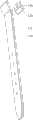
图1是本发明第一实施例提供的智能手表表带的结构示意图;Fig. 1 is a schematic structural diagram of a smart watch strap provided by the first embodiment of the present invention;
图2是本发明第一实施例提供的智能手表表带的部件分解图;Fig. 2 is an exploded view of the smart watch strap provided by the first embodiment of the present invention;
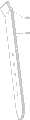
图3是本发明第一实施例提供的智能手表表带的立体图;Fig. 3 is a perspective view of the smart watch strap provided by the first embodiment of the present invention;
图4是本发明第一实施例的一种优选实施方式提供智能手表表带的A-A’剖视图;Fig. 4 is an A-A' sectional view of a smart watch strap provided by a preferred implementation of the first embodiment of the present invention;
图5是本发明第一实施例的另一种优选实施方式提供的智能手表表带的A-A’剖视图;Fig. 5 is an A-A' cross-sectional view of the smart watch strap provided by another preferred embodiment of the first embodiment of the present invention;
图6是本发明第一实施例的一种优选实施方式提供的平面单极天线的天线结构图;FIG. 6 is an antenna structure diagram of a planar monopole antenna provided in a preferred implementation manner of the first embodiment of the present invention;
图7是本发明第一实施例的另一种优选实施方式提供的平面倒F天线的天线结构图;Fig. 7 is an antenna structure diagram of a planar inverted-F antenna provided by another preferred implementation manner of the first embodiment of the present invention;
图8是本发明第一实施例的又一种优选实施方式提供的平面环天线的天线结构图;Fig. 8 is an antenna structure diagram of a planar loop antenna provided in another preferred implementation manner of the first embodiment of the present invention;
图9是本发明第一实施例的再一种优选实施方式提供的平面单极天线和平面环天线的组合天线的天线结构图;Fig. 9 is an antenna structure diagram of a combined antenna of a planar monopole antenna and a planar loop antenna provided in yet another preferred implementation manner of the first embodiment of the present invention;
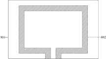
图10是本发明第二实施例提供的智能手表的结构示意图;Fig. 10 is a schematic structural diagram of a smart watch provided by the second embodiment of the present invention;
图11是本发明第二实施例提供的智能手表的立体图;Fig. 11 is a perspective view of a smart watch provided by the second embodiment of the present invention;
图12是本发明第二实施例提供的智能手表的局部放大图;Fig. 12 is a partially enlarged view of the smart watch provided by the second embodiment of the present invention;
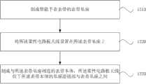
图13是本发明第三实施例提供的柔性电路板天线的装配方法的流程图;Fig. 13 is a flow chart of the method for assembling the flexible circuit board antenna provided by the third embodiment of the present invention;
图14是本发明第四实施例提供的柔性电路板天线的装配方法的流程图。Fig. 14 is a flow chart of the method for assembling the flexible circuit board antenna provided by the fourth embodiment of the present invention.
具体实施方式Detailed ways
下面结合附图和实施例对本发明作进一步的详细说明。可以理解的是,此处所描述的具体实施例仅用于解释本发明,而非对本发明的限定。另外还需要说明的是,为了便于描述,附图中仅示出了与本发明相关的部分而非全部内容。The present invention will be further described in detail below in conjunction with the accompanying drawings and embodiments. It should be understood that the specific embodiments described here are only used to explain the present invention, but not to limit the present invention. In addition, it should be noted that, for the convenience of description, only parts related to the present invention are shown in the drawings but not all content.
图1至图9示出了本发明的第一实施例。1 to 9 show a first embodiment of the present invention.
图1是本发明第一实施例提供的智能手表表带的主视图。Fig. 1 is a front view of a smart watch strap provided by the first embodiment of the present invention.
图2是本发明第一实施例提供的智能手表表带的部件分解图。参见图2,所述智能手表表带包括:表带基座110、柔性电路板天线120以及表带本体130。Fig. 2 is an exploded view of the smart watch strap provided by the first embodiment of the present invention. Referring to FIG. 2 , the smart watch strap includes: a
示例性的,所述表带基座110可为塑胶表带基座,其由塑胶注塑形成。所述塑胶是硬胶,可以保证所述柔性电路板天线的位置固定,形状不变,从而保证良好的通信性能。并且,所述表带基座110与所述智能手表的主体底座的表带连接端相连。Exemplarily, the
所述柔性电路板天线120是所述智能手表表带内包括的天线,用于发送和接收射频信号。所述柔性电路板天线120包括柔性基板和设置于所述柔性基板上的天线贴片。所述柔性基板是形成所述柔性电路板天线的基板。所述天线贴片是通过光刻或者腐蚀形成在所述柔性基板上的,用于发送和接收射频信号的天线贴片。The flexible
所述表带本体130是所述智能手表表带的本体部分,用于用户佩戴所述智能手表时将所述智能手表固定在用户的手腕上。示例性的,所述表带本体130可是软胶表带本体。所述塑胶是硬胶,可以保证所述柔性电路板天线的位置固定,形状不变,从而保证良好的通信性能。The
所述表带本体130包括基座连接部131。所述基座连接部131可以通过二次注塑成型与所述表带基座110连接,也可以通过所述基座连接部上的扣合机构与所述表带基座110连接。The
图3是本发明第一实施例提供的智能手表表带的立体图。参见图3,所述表带本体130与所述表带基座110连接后,所述柔性电路板天线120位于所述表带基座110和所述表带本体130之间,并且被所述表带基座110和所述表带本体130完全包覆。因此,来自外界的碰撞、摩擦不易对所述柔性电路板天线造成损坏。Fig. 3 is a perspective view of the smart watch strap provided by the first embodiment of the present invention. Referring to FIG. 3, after the
图4是本发明第一实施例提供的一种优选实施方式提供的智能手表表带的A-A’剖视图。参见图4,所述智能手表表带包括表带基座110、柔性电路板天线以及基座连接部131,其中,所述柔性电路板天线包括柔性基板121以及天线底座122。Fig. 4 is an A-A' sectional view of a smart watch strap provided in a preferred implementation manner provided by the first embodiment of the present invention. Referring to FIG. 4 , the smart watch strap includes a
在本实施方式中,所述基座连接部131通过二次注塑成型,并且,二次注塑成型后,所述基座连接部131与所述表带基座110相连。In this embodiment, the
图5是本发明第二实施例提供的另一种优选实施方式提供的智能手表表带的A-A’剖视图。参见图5,所述智能手表表带包括表带基座110、柔性电路板天线以及基座连接部131,其中,所述柔性电路板天线包括柔性基板121以及天线底座122。Fig. 5 is an A-A' cross-sectional view of a smart watch strap provided by another preferred embodiment provided by the second embodiment of the present invention. Referring to FIG. 5 , the smart watch strap includes a
在本实施方式中,所述基座连接部131通过所述基座连接部上的扣合机构与所述表带基座110固定连接。In this embodiment, the
图6是本发明第一实施例的一种优选实施方式提供的平面单极天线的天线结构图。所述平面单极天线包括天线贴片601、槽线602以及馈电点603。这种天线设计简单,并能通过增加不同长度的槽线增加多个谐振点。Fig. 6 is an antenna structure diagram of a planar monopole antenna provided by a preferred implementation manner of the first embodiment of the present invention. The planar monopole antenna includes an
图7是本发明第一实施例的另一种优选实施方式提供的平面倒F天线的天线结构图。与上一优选实施方式提供的平面单极天线相同,所述平面倒F天线也包括天线贴片701、槽线702以及馈电点703。这种天线同样具有结构简单,频带较宽的优点。Fig. 7 is an antenna structure diagram of a planar inverted-F antenna provided by another preferred implementation manner of the first embodiment of the present invention. Same as the planar monopole antenna provided in the previous preferred embodiment, the planar inverted-F antenna also includes an antenna patch 701 , a slot line 702 and a feed point 703 . This antenna also has the advantages of simple structure and wide frequency band.
图8是本发明第一实施例的又一种优选实施方式提供的平面环天线的天线结构图。所述平面环天线包括基底801和矩形匝线圈802。所述矩形匝线圈802与馈电线相连接实现对所述平面环天线的馈电。Fig. 8 is an antenna structure diagram of a planar loop antenna provided by yet another preferred implementation manner of the first embodiment of the present invention. The planar loop antenna includes a
图9是本发明第一实施例的再一种优选实施方式提供的平面单极天线和平面环天线的组合天线的天线结构图。所述平面单机天线和平面环天线的组合天线包括位于所述组合天线的左侧的环形结构901、位于所述组合天线右侧的单极结构902以及馈电点903。位于所述组合天线左侧的环形结构901实际上起到了对右侧的单极结构902的调谐作用,增大了天线的带宽,是天线能够覆盖更多的无线频段。FIG. 9 is an antenna structure diagram of a combined antenna of a planar monopole antenna and a planar loop antenna provided in yet another preferred implementation manner of the first embodiment of the present invention. The combination antenna of the planar stand-alone antenna and the planar loop antenna includes a
本领域普通技术人员应该理解,图6至图9示出的天线结构仅仅用于说明所述柔性电路板天线可能的结构,并不用于限定所述柔性电路板天线的实现。任何通过光刻或者腐蚀形成的平面单极天线、平面倒F天线、平面环天线,或者它们之间的任意组合,都是所述柔性电路板天线可能的实现方式。Those skilled in the art should understand that the antenna structures shown in FIGS. 6 to 9 are only used to illustrate possible structures of the flexible circuit board antenna, and are not intended to limit the implementation of the flexible circuit board antenna. Any planar monopole antenna, planar inverted-F antenna, planar loop antenna, or any combination thereof formed by photolithography or etching are possible implementations of the flexible printed circuit board antenna.
本实施例提供的智能手表表带包括与表带基座牢固粘接的柔性电路板天线,并在所述柔性电路板天线外面包覆智能手表表带,不仅将所述智能手表的天线部件从智能手表主体的内部移出,节省了智能手表的内部空间,减弱了其他部件对天线部件的干扰,而且柔性电路板天线与智能手表的表带紧密结合,在外界碰撞或者摩擦的影响下不易损坏。The smart watch strap provided by this embodiment includes a flexible circuit board antenna firmly bonded to the strap base, and the smart watch strap is covered on the outside of the flexible circuit board antenna, not only the antenna part of the smart watch is removed from the The inside of the main body of the smart watch is moved out, saving the internal space of the smart watch and weakening the interference of other components on the antenna component, and the flexible circuit board antenna is closely combined with the strap of the smart watch, which is not easy to be damaged under the influence of external collision or friction.
图10至图12示出了本发明的第二实施例。10 to 12 show a second embodiment of the present invention.
图10是本发明第二实施例提供的智能手表的主视图。参见图10,所述智能手表包括:智能手表主体1010以及智能手表表带1020。Fig. 10 is a front view of the smart watch provided by the second embodiment of the present invention. Referring to FIG. 10 , the smart watch includes: a
所述智能手表主体1010是所述智能手表的主要组成部分,所述智能手表的重要部件如中央处理单元、存储器、显示面板、触敏表面等都集成在所述智能手表主体1010的内部。The smart watch
所述智能手表主体1010的内部安装有所述智能手表的电路板。所述电路板是一块印刷电路板,它可以是单层印刷电路板,也可以是双层或多层印刷电路板。所述电路板上焊接有中央处理单元、存储器等器件。The circuit board of the smart watch is installed inside the smart watch
所述智能手表表带1020与本发明第一实施例中所述智能手表表带相同,在此不再赘述。The
图11是本发明第二实施例提供的智能手表的立体图。参见图11,所述智能手表包括智能手表主体底座1011、智能手表表带1020以及连接线1030。所述智能手表主体底座1011是所述智能手表主体1010的底座,它与智能手表主体上盖共同形成了所述智能手表主体1010的壳体。所述智能手表的电路板、中央处理单元、存储器等部件都设置在所述智能手表主体的壳体内。Fig. 11 is a perspective view of a smart watch provided by the second embodiment of the present invention. Referring to FIG. 11 , the smart watch includes a smart
所述连接线1030用于连接所述智能手表的柔性电路板天线和所述智能手表的电路板。在本实施例中,所述连接线是带状线。The
图12是本发明第二实施例提供的智能手表的局部放大图。参见图12,所述连接线1030设置在所述智能手表主体底座1011上,其一端通过所述智能手表的表带连接端上的开口与所述柔性电路板天线相连接,另一端与所述智能手表的电路板相连接,从而实现所述智能手表的射频信号的无线发送和接收。其中,所述开口设置在所述智能手表的表带连接端上,用于通过与所述柔性电路板天线相连接的连接线。Fig. 12 is a partially enlarged view of the smart watch provided by the second embodiment of the present invention. Referring to Fig. 12, the connecting
本实施例提供的智能手表利用粘结剂将柔性电路板天线与表带基座牢固粘接,并将表带本体牢固连接在所述柔性电路板天线上方,不仅将所述智能手表的天线部件从智能手表主体的内部移出,节省了智能手表的内部空间,减弱了其他部件对天线部件的干扰,而且柔性电路板天线与智能手表的表带紧密结合,在外界碰撞或者摩擦的影响下不易损坏。The smart watch provided in this embodiment uses an adhesive to firmly bond the flexible circuit board antenna to the strap base, and firmly connects the strap body above the flexible circuit board antenna, not only the antenna part of the smart watch Moving out from the inside of the main body of the smart watch saves the internal space of the smart watch and weakens the interference of other components on the antenna components, and the flexible circuit board antenna is closely combined with the strap of the smart watch, which is not easy to be damaged under the influence of external collision or friction .
图13示出了本发明的第三实施例。Fig. 13 shows a third embodiment of the present invention.
图13是本发明第三实施例提供的柔性电路板天线的装配方法的流程图。本实施例提供的装配方法可用于实现图1所示的智能手表表带。参见图13,所述柔性电路板天线的装配方法包括:步骤1310,制成智能手表表带的表带基座;步骤1320,将所述柔性电路板天线设置在所述表带基座上;步骤1330,制成与所述表带基座相连的表带本体,所述柔性电路板天线位于所述表带本体的基座连接部与表带基座之间。Fig. 13 is a flow chart of the method for assembling the flexible circuit board antenna provided by the third embodiment of the present invention. The assembly method provided in this embodiment can be used to realize the smart watch strap shown in FIG. 1 . Referring to Fig. 13, the assembly method of the flexible circuit board antenna includes:
在步骤1310中,制成智能手表表带的表带基座。In
所述表带基座是所述智能手表表带的一部分,主要用于承载所述智能手表表带中的柔性电路板天线。所述表带基座是塑胶表带基座,并且,所述表带基座通过塑胶注塑成型而形成。所述塑胶是硬胶,可以保证所述柔性电路板天线的位置固定,形状不变,从而保证良好的通信性能。The strap base is a part of the smart watch strap, and is mainly used to carry the flexible circuit board antenna in the smart watch strap. The strap base is a plastic strap base, and the strap base is formed by plastic injection molding. The plastic is hard glue, which can ensure the fixed position and shape of the flexible circuit board antenna, thereby ensuring good communication performance.
在步骤1320中,将所述柔性电路板天线设置在所述表带基座上。In
所述柔性电路板天线是所述智能手表表带中的天线部件,用于为智能手表发送和接收射频信号。用塑胶注塑成型形成所述表带基座后,需要将所述柔性电路板天线设置在所述表带基座上。在本实施例的一种优选实施方式中,利用粘结剂将所述柔性电路板天线粘接在所述表带基座上。所述粘结剂可以是热熔胶,也可以是其他用于粘接塑胶的粘结剂。The flexible circuit board antenna is an antenna component in the smart watch strap, and is used for sending and receiving radio frequency signals for the smart watch. After the watchband base is formed by plastic injection molding, the flexible circuit board antenna needs to be arranged on the watchband base. In a preferred implementation manner of this embodiment, the flexible circuit board antenna is bonded to the watchband base with an adhesive. The adhesive can be hot melt adhesive, or other adhesives used for bonding plastics.
在步骤1330中,制成与所述表带基座相连的表带本体,所述柔性电路板天线位于所述表带本体的基座连接部与表带基座之间。In
在本实施例的一种优选实施方式中,所述制成与所述表带基座相连的表带本体的步骤是在所述表带基座上设置有所述柔性电路板天线的一面二次注塑软胶,形成所述表带本体。所述软胶质地柔软,因而由软胶形成的表带本体也比较柔软,可任意弯曲。因此,由软胶制成表带本体可以增加用户佩戴智能手表的舒适度。In a preferred implementation of this embodiment, the step of making the strap body connected to the strap base is to set one side of the flexible circuit board antenna on the strap base. Secondary injection of soft rubber to form the strap body. The soft rubber is soft in texture, so the strap body formed by the soft rubber is relatively soft and can be bent arbitrarily. Therefore, the strap body made of soft rubber can increase the comfort of the user wearing the smart watch.
在本实施例的另一种优选实施方式中,所述制成与所述表带基座相连的表带本体的步骤是用软胶制成包括具有扣合机构的基座连接部的所述表带本体后,通过所述扣合机构,将所述表带本体与所述表带基座相连。In another preferred implementation of this embodiment, the step of making the strap body connected to the strap base is to use soft rubber to make the strap body including the base connection part with a buckle mechanism. After the strap body, the strap body is connected to the strap base through the fastening mechanism.
本实施例通过将智能手表的柔性电路板天线粘接在所述智能手表的表带基座上,并将表带与所述表带基座扣合,将智能手表的柔性电路板天线牢固设置在所述表带的内部,节省了所述智能手表的内部空间,有利于智能手表的小型化,并且有效防止了外界的碰撞和摩擦对所述柔性电路板天线的损坏。In this embodiment, by bonding the flexible circuit board antenna of the smart watch to the strap base of the smart watch, and fastening the strap with the strap base, the flexible circuit board antenna of the smart watch is firmly arranged Inside the strap, the internal space of the smart watch is saved, which is beneficial to the miniaturization of the smart watch, and effectively prevents external collision and friction from damaging the flexible circuit board antenna.
图14示出了本发明的第四实施例。Fig. 14 shows a fourth embodiment of the present invention.
图14是本发明第四实施例提供的柔性电路板天线的装配方法的流程图。本实施例提供的方法可用于实现图10所示的智能手表。参见图14,所述柔性电路板天线的装配方法包括:步骤1410,制成智能手表表带的表带基座;步骤1420,将所述柔性电路板天线设置在所述表带基座上;步骤1430,制成与所述表带基座相连的表带本体,所述柔性电路板天线位于所述表带本体的基座连接部与表带基座之间;以及步骤1440,将所述柔性电路板天线的天线贴片通过所述智能手表的表带连接端上的开口与所述智能手表的电路板连接。Fig. 14 is a flow chart of the method for assembling the flexible circuit board antenna provided by the fourth embodiment of the present invention. The method provided in this embodiment can be used to implement the smart watch shown in FIG. 10 . Referring to Fig. 14, the assembly method of the flexible circuit board antenna includes: step 1410, making a strap base of a smart watch strap; step 1420, setting the flexible circuit board antenna on the strap base; Step 1430, make a strap body connected to the strap base, the flexible circuit board antenna is located between the base connection part of the strap body and the strap base; and step 1440, the The antenna patch of the flexible circuit board antenna is connected to the circuit board of the smart watch through the opening on the strap connection end of the smart watch.
在本实施例中,步骤1410与本发明第三实施例中的步骤1310相同,步骤1420与本发明第三实施例中的步骤1320相同,步骤1430与本发明第四实施例中的步骤1330相同,在此不再一一赘述。In this embodiment, step 1410 is the same as
在步骤1440中,将所述柔性电路板天线的天线贴片通过所述智能手表的表带连接端上的开口与所述智能手表的电路板连接。In step 1440, the antenna patch of the flexible circuit board antenna is connected to the circuit board of the smart watch through the opening on the strap connection end of the smart watch.
所述智能手表主体包括表带连接端,所述表带连接端上设有开口。通过所述开口将所述柔性电路板天线的天线贴片与所述智能手表的电路板连接,使得所述智能手表可以通过所述柔性电路板天线完成射频信号的发送和接收。The main body of the smart watch includes a strap connection end, and an opening is arranged on the strap connection end. The antenna patch of the flexible circuit board antenna is connected to the circuit board of the smart watch through the opening, so that the smart watch can complete the sending and receiving of radio frequency signals through the flexible circuit board antenna.
本实施例通过将智能手表的柔性电路板天线粘接在所述智能手表的表带基座上,并将表带与所述表带基座扣合,将智能手表的柔性电路板天线牢固设置在所述表带的内部,节省了所述智能手表的内部空间,有利于智能手表的小型化,并且有效防止了外界的碰撞和摩擦对所述柔性电路板天线的损坏。In this embodiment, by bonding the flexible circuit board antenna of the smart watch to the strap base of the smart watch, and fastening the strap with the strap base, the flexible circuit board antenna of the smart watch is firmly arranged Inside the strap, the internal space of the smart watch is saved, which is beneficial to the miniaturization of the smart watch, and effectively prevents external collision and friction from damaging the flexible circuit board antenna.
本说明书中的各个实施例均采用递进的方式描述,每个实施例重点说明的都是与其他实施例的不同之处,各个实施例之间的相同相似的部分互相参见即可。Each embodiment in this specification is described in a progressive manner, each embodiment focuses on the difference from other embodiments, and the same and similar parts between the various embodiments can be referred to each other.
以上所述仅为本发明的优选实施例,并不用于限制本发明,对于本领域技术人员而言,本发明可以有各种改动和变化。凡在本发明的精神和原理之内所作的任何修改、等同替换、改进等,均应包含在本发明的保护范围之内。The above descriptions are only preferred embodiments of the present invention, and are not intended to limit the present invention. For those skilled in the art, the present invention may have various modifications and changes. Any modification, equivalent replacement, improvement, etc. made within the spirit and principle of the present invention shall be included in the protection scope of the present invention.
Claims (10)
Priority Applications (1)
| Application Number | Priority Date | Filing Date | Title |
|---|---|---|---|
| CN201310437010.7ACN103488076A (en) | 2013-09-23 | 2013-09-23 | Smart watch strap, smart watch and assembly method of flexible circuit board antenna |
Applications Claiming Priority (1)
| Application Number | Priority Date | Filing Date | Title |
|---|---|---|---|
| CN201310437010.7ACN103488076A (en) | 2013-09-23 | 2013-09-23 | Smart watch strap, smart watch and assembly method of flexible circuit board antenna |
Publications (1)
| Publication Number | Publication Date |
|---|---|
| CN103488076Atrue CN103488076A (en) | 2014-01-01 |
Family
ID=49828395
Family Applications (1)
| Application Number | Title | Priority Date | Filing Date |
|---|---|---|---|
| CN201310437010.7APendingCN103488076A (en) | 2013-09-23 | 2013-09-23 | Smart watch strap, smart watch and assembly method of flexible circuit board antenna |
Country Status (1)
| Country | Link |
|---|---|
| CN (1) | CN103488076A (en) |
Cited By (25)
| Publication number | Priority date | Publication date | Assignee | Title |
|---|---|---|---|---|
| CN104305651A (en)* | 2014-10-08 | 2015-01-28 | 深圳市兰丁科技有限公司 | Intelligent finger ring integrated with antenna |
| CN104682143A (en)* | 2015-03-25 | 2015-06-03 | 深圳市陨石通信设备有限公司 | Wearable digital terminal |
| CN104665130A (en)* | 2015-03-25 | 2015-06-03 | 深圳市陨石通信设备有限公司 | Watchband and transmission device applied to smart watch |
| WO2016000384A1 (en)* | 2014-07-04 | 2016-01-07 | 信维创科通信技术(北京)有限公司 | Radio communication antenna suitable for wearable device and wearable device |
| CN105929681A (en)* | 2016-06-30 | 2016-09-07 | 广州润芯信息技术有限公司 | SOS automatic time service smart watch based on first generation of Beidou satellite navigation system |
| WO2016188106A1 (en)* | 2015-05-27 | 2016-12-01 | 深圳市鼎芯东方科技有限公司 | Smart watch |
| CN106463837A (en)* | 2015-01-29 | 2017-02-22 | 华为技术有限公司 | Wearable device |
| CN106539568A (en)* | 2015-12-10 | 2017-03-29 | 悦享趋势科技(北京)有限责任公司 | Wearable physiological monitoring equipment and its antenna system |
| CN107077102A (en)* | 2017-01-16 | 2017-08-18 | 深圳市大疆创新科技有限公司 | Wrist-watch and its watchband |
| US9877549B2 (en) | 2014-08-11 | 2018-01-30 | Apple Inc. | Attachment system for an electronic device |
| WO2018018731A1 (en)* | 2016-07-26 | 2018-02-01 | 深圳市见康云科技有限公司 | Smart watch |
| US9894964B2 (en) | 2014-08-11 | 2018-02-20 | Apple Inc. | Consumer product attachment systems having a locking assembly |
| US9926953B2 (en) | 2013-03-15 | 2018-03-27 | Apple Inc. | Attachment apparatuses and associated methods of use and manufacture |
| US9949537B2 (en) | 2015-03-06 | 2018-04-24 | Apple Inc. | Clasp mechanism for wrist-worn devices |
| US10016029B2 (en) | 2014-08-09 | 2018-07-10 | Apple Inc. | Attachment systems for electronic devices |
| US10064460B2 (en) | 2015-09-30 | 2018-09-04 | Apple Inc. | Frictional stabilization of band and securement mechanism |
| WO2018166060A1 (en)* | 2017-03-17 | 2018-09-20 | 深圳市大疆创新科技有限公司 | Wearable remote control device and aircraft having same |
| US10149518B1 (en) | 2016-08-08 | 2018-12-11 | Apple Inc. | Clasp assembly for a wearable device |
| CN109149105A (en)* | 2018-10-19 | 2019-01-04 | 深圳汉阳天线设计有限公司 | A kind of radiating antenna and smartwatch |
| US10184506B2 (en) | 2014-08-11 | 2019-01-22 | Apple Inc. | Captive elements of an attachment system |
| CN109417218A (en)* | 2016-06-22 | 2019-03-01 | 阿莫技术有限公司 | Loop antenna module and jig for manufacturing the same |
| US10219591B2 (en) | 2016-03-21 | 2019-03-05 | Apple Inc. | Attachment system for an electronic device |
| US10424832B2 (en) | 2017-10-20 | 2019-09-24 | Elements of Genius, Inc. | Wearable device antenna apparatus and system |
| CN113078454A (en)* | 2021-04-07 | 2021-07-06 | 苏州沙岸通信科技有限公司 | 5G antenna and intelligent wrist-watch |
| CN115097716A (en)* | 2022-06-25 | 2022-09-23 | 平安银行股份有限公司 | Smart watch and its strap |
Citations (6)
| Publication number | Priority date | Publication date | Assignee | Title |
|---|---|---|---|---|
| GB2107966A (en)* | 1981-08-31 | 1983-05-11 | Satoh Manufacture Co Ltd | Watch strap |
| US6329903B1 (en)* | 1994-08-18 | 2001-12-11 | Oi Denki Co., Ltd. | Wrist watch-style pager |
| CN201285497Y (en)* | 2008-09-16 | 2009-08-05 | 微渧科技有限公司 | Watch shaped apparatus equipped with wireless electronic component |
| CN102063050A (en)* | 2010-09-03 | 2011-05-18 | 鸿富锦精密工业(深圳)有限公司 | Wrist type electronic device with antenna |
| CN102496772A (en)* | 2011-12-16 | 2012-06-13 | 上海华勤通讯技术有限公司 | FPC (flexible printed circuit) antenna |
| CN202454722U (en)* | 2012-02-01 | 2012-09-26 | 王辉 | Watch strap with antenna |
- 2013
- 2013-09-23CNCN201310437010.7Apatent/CN103488076A/enactivePending
Patent Citations (6)
| Publication number | Priority date | Publication date | Assignee | Title |
|---|---|---|---|---|
| GB2107966A (en)* | 1981-08-31 | 1983-05-11 | Satoh Manufacture Co Ltd | Watch strap |
| US6329903B1 (en)* | 1994-08-18 | 2001-12-11 | Oi Denki Co., Ltd. | Wrist watch-style pager |
| CN201285497Y (en)* | 2008-09-16 | 2009-08-05 | 微渧科技有限公司 | Watch shaped apparatus equipped with wireless electronic component |
| CN102063050A (en)* | 2010-09-03 | 2011-05-18 | 鸿富锦精密工业(深圳)有限公司 | Wrist type electronic device with antenna |
| CN102496772A (en)* | 2011-12-16 | 2012-06-13 | 上海华勤通讯技术有限公司 | FPC (flexible printed circuit) antenna |
| CN202454722U (en)* | 2012-02-01 | 2012-09-26 | 王辉 | Watch strap with antenna |
Cited By (47)
| Publication number | Priority date | Publication date | Assignee | Title |
|---|---|---|---|---|
| US9926953B2 (en) | 2013-03-15 | 2018-03-27 | Apple Inc. | Attachment apparatuses and associated methods of use and manufacture |
| US10914329B2 (en) | 2013-03-15 | 2021-02-09 | Apple Inc. | Attachment apparatuses and associated methods of use and manufacture |
| US11480202B2 (en) | 2013-03-15 | 2022-10-25 | Apple Inc. | Attachment apparatuses and associated methods of use and manufacture |
| US11614108B2 (en) | 2013-03-15 | 2023-03-28 | Apple Inc. | Attachment apparatuses and associated methods of use and manufacture |
| US10132340B2 (en) | 2013-03-15 | 2018-11-20 | Apple Inc. | Attachment apparatuses and associated methods of use and manufacture |
| WO2016000384A1 (en)* | 2014-07-04 | 2016-01-07 | 信维创科通信技术(北京)有限公司 | Radio communication antenna suitable for wearable device and wearable device |
| US10893726B2 (en) | 2014-08-09 | 2021-01-19 | Apple Inc. | Attachment systems for electronic devices |
| US11503885B2 (en) | 2014-08-09 | 2022-11-22 | Apple Inc. | Attachment systems for electronic devices |
| US10016029B2 (en) | 2014-08-09 | 2018-07-10 | Apple Inc. | Attachment systems for electronic devices |
| US11717060B2 (en) | 2014-08-11 | 2023-08-08 | Apple Inc. | Attachment system for an electronic device |
| US10264857B2 (en) | 2014-08-11 | 2019-04-23 | Apple Inc. | Attachment system for an electronic device |
| US10945496B2 (en) | 2014-08-11 | 2021-03-16 | Apple Inc. | Consumer product attachment systems having locking or expansion characteristics |
| US9894964B2 (en) | 2014-08-11 | 2018-02-20 | Apple Inc. | Consumer product attachment systems having a locking assembly |
| US12127636B2 (en) | 2014-08-11 | 2024-10-29 | Apple Inc. | Attachment system for an electronic device |
| US10575602B2 (en) | 2014-08-11 | 2020-03-03 | Apple Inc. | Consumer product attachment systems having a locking assembly |
| US11026484B2 (en) | 2014-08-11 | 2021-06-08 | Apple Inc. | Attachment system for an electronic device |
| US11723443B2 (en) | 2014-08-11 | 2023-08-15 | Apple Inc. | Consumer product attachment systems having locking or expansion characteristics |
| US9877549B2 (en) | 2014-08-11 | 2018-01-30 | Apple Inc. | Attachment system for an electronic device |
| US10182623B2 (en) | 2014-08-11 | 2019-01-22 | Apple Inc. | Consumer product attachment systems having locking or expansion characteristics |
| US10085523B2 (en) | 2014-08-11 | 2018-10-02 | Apple Inc. | Attachment system for an electronic device |
| US10184506B2 (en) | 2014-08-11 | 2019-01-22 | Apple Inc. | Captive elements of an attachment system |
| CN104305651A (en)* | 2014-10-08 | 2015-01-28 | 深圳市兰丁科技有限公司 | Intelligent finger ring integrated with antenna |
| CN104305651B (en)* | 2014-10-08 | 2016-03-09 | 深圳市兰丁科技有限公司 | Antenna integrated intelligent ring |
| US10126780B2 (en) | 2015-01-29 | 2018-11-13 | Huawei Technologies Co., Ltd. | Slot antenna for a wearable device |
| CN106463837A (en)* | 2015-01-29 | 2017-02-22 | 华为技术有限公司 | Wearable device |
| US9949537B2 (en) | 2015-03-06 | 2018-04-24 | Apple Inc. | Clasp mechanism for wrist-worn devices |
| US11006705B2 (en) | 2015-03-06 | 2021-05-18 | Apple Inc. | Clasp mechanism for wrist-worn devices |
| CN104682143A (en)* | 2015-03-25 | 2015-06-03 | 深圳市陨石通信设备有限公司 | Wearable digital terminal |
| CN104665130A (en)* | 2015-03-25 | 2015-06-03 | 深圳市陨石通信设备有限公司 | Watchband and transmission device applied to smart watch |
| WO2016188106A1 (en)* | 2015-05-27 | 2016-12-01 | 深圳市鼎芯东方科技有限公司 | Smart watch |
| US10064460B2 (en) | 2015-09-30 | 2018-09-04 | Apple Inc. | Frictional stabilization of band and securement mechanism |
| CN106539568A (en)* | 2015-12-10 | 2017-03-29 | 悦享趋势科技(北京)有限责任公司 | Wearable physiological monitoring equipment and its antenna system |
| US10219591B2 (en) | 2016-03-21 | 2019-03-05 | Apple Inc. | Attachment system for an electronic device |
| CN109417218A (en)* | 2016-06-22 | 2019-03-01 | 阿莫技术有限公司 | Loop antenna module and jig for manufacturing the same |
| US10998619B2 (en) | 2016-06-22 | 2021-05-04 | Amotech Co., Ltd. | Ring type antenna module and jig for manufacturing same |
| CN105929681A (en)* | 2016-06-30 | 2016-09-07 | 广州润芯信息技术有限公司 | SOS automatic time service smart watch based on first generation of Beidou satellite navigation system |
| WO2018018731A1 (en)* | 2016-07-26 | 2018-02-01 | 深圳市见康云科技有限公司 | Smart watch |
| US10149518B1 (en) | 2016-08-08 | 2018-12-11 | Apple Inc. | Clasp assembly for a wearable device |
| WO2018129730A1 (en)* | 2017-01-16 | 2018-07-19 | 深圳市大疆创新科技有限公司 | Watch and watchband thereof |
| CN107077102A (en)* | 2017-01-16 | 2017-08-18 | 深圳市大疆创新科技有限公司 | Wrist-watch and its watchband |
| CN109716582A (en)* | 2017-03-17 | 2019-05-03 | 深圳市大疆创新科技有限公司 | Wearable remote control equipment and aircraft with the wearable remote control equipment |
| WO2018166060A1 (en)* | 2017-03-17 | 2018-09-20 | 深圳市大疆创新科技有限公司 | Wearable remote control device and aircraft having same |
| US10424832B2 (en) | 2017-10-20 | 2019-09-24 | Elements of Genius, Inc. | Wearable device antenna apparatus and system |
| CN109149105A (en)* | 2018-10-19 | 2019-01-04 | 深圳汉阳天线设计有限公司 | A kind of radiating antenna and smartwatch |
| CN109149105B (en)* | 2018-10-19 | 2024-04-02 | 深圳汉阳天线设计有限公司 | Radiation antenna and intelligent watch |
| CN113078454A (en)* | 2021-04-07 | 2021-07-06 | 苏州沙岸通信科技有限公司 | 5G antenna and intelligent wrist-watch |
| CN115097716A (en)* | 2022-06-25 | 2022-09-23 | 平安银行股份有限公司 | Smart watch and its strap |
Similar Documents
| Publication | Publication Date | Title |
|---|---|---|
| CN103488076A (en) | Smart watch strap, smart watch and assembly method of flexible circuit board antenna | |
| KR101916241B1 (en) | Antenna apparatus for portable terminal | |
| KR101658766B1 (en) | Multipurpose antenna | |
| JP5084929B2 (en) | Antenna pattern frame, electronic device case and its manufacturing mold | |
| US9450294B2 (en) | Antenna apparatus for portable terminal | |
| US9966651B2 (en) | Antenna and wireless communication device using the same | |
| US20080119138A1 (en) | Bluetooth headset with built-in antenna module | |
| CN201749938U (en) | Multi-band built-in antenna device for portable terminal | |
| US8948827B2 (en) | Mobile communication device | |
| KR102049791B1 (en) | A portable terminal having a speaker module and method for manufacturing thereof | |
| JP2012010317A (en) | Case having antenna with active module and electronic device having the same | |
| KR20110016097A (en) | Built-in antenna module of portable wireless terminal | |
| CN102263322A (en) | Antenna radiator, method of manufacturing electronic device housing, and electronic device housing | |
| US8581787B2 (en) | Portable electronic device with antenna module | |
| TWI573317B (en) | Wireless communication device | |
| US20140168015A1 (en) | Mobile communication terminal | |
| KR101643928B1 (en) | Antenna structure | |
| TW201537831A (en) | Multipurpose antenna | |
| KR101025941B1 (en) | Antenna radiator and manufacturing method of antenna pattern frame using same | |
| CN104953239B (en) | A kind of NFC antenna applied to mobile terminal | |
| CN201156584Y (en) | bluetooth antenna | |
| KR101651902B1 (en) | Manufacturing method of antenna structure | |
| US20090102722A1 (en) | Inverted f-type antenna | |
| CN210350073U (en) | Antenna suitable for watch watchband | |
| KR101651903B1 (en) | Antenna structure and manufacturing method thererof |
Legal Events
| Date | Code | Title | Description |
|---|---|---|---|
| C06 | Publication | ||
| PB01 | Publication | ||
| C10 | Entry into substantive examination | ||
| SE01 | Entry into force of request for substantive examination | ||
| C12 | Rejection of a patent application after its publication | ||
| RJ01 | Rejection of invention patent application after publication | Application publication date:20140101 |