CN103487034A - Method for measuring distance and height by vehicle-mounted monocular camera based on vertical type target - Google Patents
Method for measuring distance and height by vehicle-mounted monocular camera based on vertical type targetDownload PDFInfo
- Publication number
- CN103487034A CN103487034ACN201310445576.4ACN201310445576ACN103487034ACN 103487034 ACN103487034 ACN 103487034ACN 201310445576 ACN201310445576 ACN 201310445576ACN 103487034 ACN103487034 ACN 103487034A
- Authority
- CN
- China
- Prior art keywords
- point
- corner
- template
- points
- image
- Prior art date
- Legal status (The legal status is an assumption and is not a legal conclusion. Google has not performed a legal analysis and makes no representation as to the accuracy of the status listed.)
- Granted
Links
Images


Classifications
- G—PHYSICS
- G01—MEASURING; TESTING
- G01C—MEASURING DISTANCES, LEVELS OR BEARINGS; SURVEYING; NAVIGATION; GYROSCOPIC INSTRUMENTS; PHOTOGRAMMETRY OR VIDEOGRAMMETRY
- G01C3/00—Measuring distances in line of sight; Optical rangefinders
- G—PHYSICS
- G01—MEASURING; TESTING
- G01B—MEASURING LENGTH, THICKNESS OR SIMILAR LINEAR DIMENSIONS; MEASURING ANGLES; MEASURING AREAS; MEASURING IRREGULARITIES OF SURFACES OR CONTOURS
- G01B11/00—Measuring arrangements characterised by the use of optical techniques
- G01B11/02—Measuring arrangements characterised by the use of optical techniques for measuring length, width or thickness
Landscapes
- Physics & Mathematics (AREA)
- General Physics & Mathematics (AREA)
- Electromagnetism (AREA)
- Engineering & Computer Science (AREA)
- Radar, Positioning & Navigation (AREA)
- Remote Sensing (AREA)
- Image Analysis (AREA)
- Traffic Control Systems (AREA)
Abstract
Translated fromChinese
Description
Translated fromChinese技术领域technical field
本发明属于智能车辆环境感知技术领域,涉及一种基于机器视觉的测距及测高技术,具体涉及一种基于立式标靶的车载单目摄像头针对障碍物、桥洞或涵洞等的测距及测高方法。The invention belongs to the technical field of intelligent vehicle environment perception, relates to a distance measurement and height measurement technology based on machine vision, and specifically relates to a vehicle-mounted monocular camera based on a vertical target for distance measurement and detection of obstacles, bridge holes or culverts, etc. altimetry method.
背景技术Background technique
机器视觉作为智能车辆环境感知系统中最重要的组成部分,为决策层提供大量必要的环境信息,具有十分重要的意义。其中,物体的测距与测高分别为无人驾驶或辅助驾驶系统的防撞预警、路径规划及车辆分类、涵洞桥梁通过性检测等提供重要的参数信息。目前,智能车的机器视觉测量一般分为双目视觉测量和单目视觉测量两类。双目视觉测距容易受到特征点误匹配的影响,且计算量大,难以满足实时性要求。而单目视觉测距结构简单,运算速度快,具有广泛的应用前景。As the most important part of the intelligent vehicle environment perception system, machine vision provides a large amount of necessary environmental information for the decision-making layer, which is of great significance. Among them, the distance measurement and height measurement of the object provide important parameter information for the anti-collision warning, path planning and vehicle classification of the driverless or assisted driving system, and the passability detection of culverts and bridges. At present, the machine vision measurement of smart cars is generally divided into two categories: binocular vision measurement and monocular vision measurement. Binocular vision ranging is easily affected by the mismatch of feature points, and the amount of calculation is large, so it is difficult to meet the real-time requirements. The monocular vision distance measurement has a simple structure and fast calculation speed, and has a wide range of application prospects.
目前单目视觉系统通常采用对应点标定法(简称标定法)来获取待测物体的深度信息。传统对应点标定法通常是利用棋盘格标定板标定出摄像头内外部参数后,结合投影模型,求解出图像坐标系与实际成像角度之间的对应关系,从而得到距离信息。此方法需要多次采集不同方位的标定板图像,并且需要精确记录每个点在世界坐标系和图像坐标系中的对应坐标,而且标定结果的误差会在测量中放大数十甚至上百倍,总体来说,过程复杂且误差较大。另外,通过在路面摆放参照物并测量其距离,利用参照物距离和像素数据直接拟合出距离与图像坐标间的数学模型,从而实现测距。此方法在工程中也有广泛的运用,但需要较大的场地,精度会受到实际测量和数据拟合误差的影响。而对于测高,主要还是运用激光雷达等传感器进行测量,仅用单目实时测高还鲜有发表的研究成果。At present, the monocular vision system usually adopts the corresponding point calibration method (referred to as the calibration method) to obtain the depth information of the object to be measured. The traditional corresponding point calibration method usually uses the checkerboard calibration board to calibrate the internal and external parameters of the camera, and then combines the projection model to solve the corresponding relationship between the image coordinate system and the actual imaging angle, so as to obtain the distance information. This method requires multiple acquisitions of calibration plate images in different orientations, and requires accurate recording of the corresponding coordinates of each point in the world coordinate system and the image coordinate system, and the error of the calibration results will be magnified tens or even hundreds of times during the measurement. However, the process is complicated and the error is large. In addition, by placing a reference object on the road and measuring its distance, the distance and pixel data of the reference object are used to directly fit the mathematical model between the distance and the image coordinates, thereby realizing distance measurement. This method is also widely used in engineering, but requires a larger site, and the accuracy will be affected by actual measurement and data fitting errors. As for height measurement, sensors such as lidar are mainly used for measurement, and there are few published research results only using monocular real-time height measurement.
发明内容Contents of the invention
本发明的目的在于提供一种基于立式标靶的车载单目摄像头测距测高方法,具体是通过对立式标靶图像的感兴趣区进行模板匹配、候选点聚类及筛选、精确定位等操作,实现亚像素级角点检测及定位,结合投影几何模型,建立图像纵坐标与实际成像角度之间的映射关系,从而实现测距及测高,此方法不仅提高了测量精度,且无需标定摄像头内外部参数,操作简单,可执行性强,具有较强的工程实用价值和研究意义。The purpose of the present invention is to provide a vehicle-mounted monocular camera distance measurement and height measurement method based on a vertical target, specifically by performing template matching, clustering and screening of candidate points, and precise positioning of the region of interest of the vertical target image and other operations to realize sub-pixel-level corner detection and positioning, combined with the projection geometric model, to establish the mapping relationship between the image ordinate and the actual imaging angle, so as to realize distance measurement and height measurement. This method not only improves the measurement accuracy, but also does not require Calibrating the internal and external parameters of the camera is easy to operate, highly executable, and has strong engineering practical value and research significance.
本发明提供的一种基于立式标靶的车载单目摄像头测距测高方法,包括以下步骤:A method for measuring the distance and height of a vehicle-mounted monocular camera based on a vertical target provided by the present invention comprises the following steps:
步骤101:摄像头安装于车体的合适位置后,首先将立式标靶放置于摄像头正前方,且尽量靠近摄像头的同时,需满足采集的标靶图像中必须包含最低的角点,且角点总数大于8个,然后测量摄像头安装高度h及其与立式标靶靶面的水平距离D;Step 101: After the camera is installed at a suitable position on the car body, first place the vertical target directly in front of the camera, and as close as possible to the camera, the minimum corner must be included in the collected target image, and the corner The total number is more than 8, then measure the camera installation height h and the horizontal distance D from the vertical target surface;
步骤102:采集标靶图像,分辨率为mm*nn,设置图像坐标系:左上角点为坐标原点,水平向右为x轴正方向,垂直向下为y轴正方向。设置角点检测的感兴趣区:x方向为[mm/3-1,2*mm/3-1],y方向为[0,nn-1]。对感兴趣区进行分块:块大小s*v可以调整,但一般大于50*50,对每个块分别采用最大类间方差法进行自适应二值化处理;Step 102: Collect target images with a resolution of mm*nn, and set the image coordinate system: the upper left corner point is the origin of the coordinates, horizontally to the right is the positive direction of the x-axis, and vertically downward is the positive direction of the y-axis. Set the ROI for corner detection: the x direction is [mm/3-1,2*mm/3-1], and the y direction is [0,nn-1]. Block the area of interest: the block size s*v can be adjusted, but it is generally greater than 50*50, and the maximum inter-class variance method is used for each block to perform adaptive binarization;
步骤103:在感兴趣区内利用设计的模板(a)和(b)分别进行全搜索匹配,保留所有匹配子图的左上角点,组成标靶角点的候选点集CC={(x1,y1),(x2,y2),…,(xk,yk)},其中k为匹配的子图总数;Step 103: Use the designed templates (a) and (b) to perform full search and matching in the region of interest, retain the upper left corner points of all matching subimages, and form the candidate point set CC={(x1 ,y1 ),(x2 ,y2 ),…,(xk ,yk )}, where k is the total number of matching subgraphs;
步骤104:对候选点集CC中所有点进行分类,即将两点之间横坐标差值及纵坐标差值同时小于阈值T1的点记为同一小类,假设总共分成了g小类,则小类的集W={w1,w2,…,wg},再分别计算各小类的中心点坐标(xwi,ywi)(i=1,2,…,g),将中心点横坐标之差小于T1的小类记为同一个大类,最后保留包含小类数目最多的大类,剔除其他小类,并将保留下来的小类的中心点坐标在x和y方向上分别加上模板宽度和高度的一半e,存为初始角点集A={(xa1,ya1),(xa2,ya2),…,(xaj,yaj)},其中j为保留下来的小类的个数,而且A中各点的顺序是以ya1,ya2,…,yaj值从大到小排列;Step 104: Classify all points in the candidate point set CC, that is, the points whose abscissa and ordinate differences between two points are both smaller than the threshold T1 are recorded as the same subclass, assuming that they are divided into g subclasses in total, then The set of subclasses W={w1 ,w2 ,…,wg }, and then calculate the center point coordinates (xwi ,ywi ) (i=1,2,…,g) of each subclass respectively, and the center The subclasses whose point abscissa difference is less than T+ 1 are recorded as the same major class, and finally the major class containing the largest number of subclasses is retained, other subclasses are eliminated, and the center point coordinates of the remaining subclasses are in the x and y directions Add half e of the width and height of the template to the above, and store it as the initial corner point set A={(xa1 ,ya1 ),(xa2 ,ya2 ),…,(xaj ,yaj )}, where j is the number of small classes retained, and the order of each point in A is ya1 , ya2 ,..., yaj values are arranged from large to small;
步骤105:在初始角点集A中搜索出最大横坐标值xmax,利用模板(c)在横坐标小于xmax-e的感兴趣区内从上至下、从右至左搜索匹配的子图,一旦搜索到,则停止搜索。假设搜索到匹配的子图左上角点为(xf,yf),则角点的参考间隔ss=xmax-(xf+e),再利用模板(d)在点(xf,yf)左下方感兴趣区内从上至下、从右至左搜索匹配的子图,一旦搜索到,则停止搜索,记录匹配的子图左上角点为(xj,yj);Step 105: Search for the maximum abscissa value xmax in the initial corner point set A, and usethe template (c) to search for matching sub Graph, once searched, stop searching. Assuming that the upper left corner point of the matched subgraph is (xf , yf ), then the reference interval of the corner point ss=xmax -(xf +e), and then use the template (d) at the point (xf , yf ) Search the matching subgraph from top to bottom and from right to left in the lower left ROI, once found, stop searching, and record the upper left corner point of the matching subgraph as (xj , yj );
步骤106:搜索完毕后,判断是否存在步骤105的两个定位参考点(xf,yf)和(xj,yj),如果存在进入步骤107;否则返回步骤101;Step 106: After the search is completed, judge whether there are two positioning reference points (xf , yf ) and (xj , yj ) in step 105, and if so, go to step 107; otherwise, return to step 101;
步骤107:将初始角点集A中纵坐标最大值yc1与yj进行比较,如果yc1-yj为ss的3倍左右,认为点(xc1,yc1)为标靶最低角点;否则,将点(xmax,yj+ss*3)作为标靶的最低角点,然后利用初始角点集A和参考间隔ss将图像中全部角点补充完整,并得到角点集C={(xc1,yc1),(xc2,yc2),…,(xcn,ycn)},其中n表示图中标靶角点总数,且C中各点的顺序也以y值从大到小排列,最后运用openCV中的cvFindCornerSubPix()函数,以角点集C为基准将其更新为亚像素级角点集B={(xb1,yb1),(xb2,yb2),…,(xbn,ybn)};Step 107: Compare the maximum value yc1 of the ordinate in the initial corner point set A with yj , if yc1 -yj is about 3 times of ss, consider the point (xc1 , yc1 ) to be the lowest corner point of the target ;Otherwise, take the point (xmax ,yj +ss*3) as the lowest corner point of the target, then use the initial corner point set A and the reference interval ss to complete all the corner points in the image, and get the corner point set C ={(xc1 ,yc1 ),(xc2 ,yc2 ),…,(xcn ,ycn )}, where n represents the total number of target corner points in the figure, and the order of each point in C is also based on the y value Arrange from large to small, and finally use the cvFindCornerSubPix() function in openCV to update it to a sub-pixel-level corner set B={(xb1 ,yb1 ),(xb2 ,yb2 ) based on the corner point set C ),...,(xbn ,ybn )};
步骤108:图像中n个角点的高度集HH={1.00,1.05,…,1.00+(n-1)*0.05},然后利用参数h和D,计算得到各角点的实际成像角度集Q={q1,q2,…,qn},其中各角度值与亚像素级角点集B的纵坐标{yb1,yb2,…,ybn}按顺序一一对应,得到映射点集P={(yb1,q1),(yb2,q2),…,(ybn,qn)},以直线拟合相邻两点,得到相邻点映射关系集F={f1,f2,…,fn-1};Step 108: The height set HH={1.00,1.05,...,1.00+(n-1)*0.05} of n corner points in the image, and then use the parameters h and D to calculate the actual imaging angle set Q of each corner point ={q1 ,q2 ,…,qn }, where each angle value corresponds to the vertical coordinate {yb1 ,yb2 ,…,ybn } of the sub-pixel-level corner point set B in sequence, and the mapping point is obtained Set P={(yb1 ,q1 ),(yb2 ,q2 ),…,(ybn ,qn )}, fit two adjacent points with a straight line, and get the adjacent point mapping relationship set F={ f1 ,f2 ,...,fn-1 };
步骤109:在实时测距过程中,将通过障碍物检测算法得到的障碍物底等部y方向坐标yz作为参数输入,首先判断出yz所属的映射关系fi(0<i<n),利用fi的直线方程计算yz对应的实际成像角度qZ,然后以qZ作为输入通过测距方程计算障碍物等的距离Lz;Step 109: In the process of real-time ranging, the y-direction coordinates yz of the bottom and other parts of the obstacle obtained by the obstacle detection algorithm are input as parameters, and the mapping relationship fi (0<i<n) to which yz belongs is firstly judged , use the straight line equation of fi to calculate the actual imaging angle qZ corresponding to yz , and then use qZ as input to calculate the distance Lz of obstacles, etc. through the ranging equation;
步骤110:根据系统需要判断是否需要测量障碍物等的高度,如果需要继续步骤111;否则结束此障碍物等的测距;Step 110: According to the needs of the system, judge whether it is necessary to measure the height of obstacles, etc., if necessary, continue to step 111; otherwise, end the distance measurement of obstacles, etc.;
步骤111:将通过障碍物检测算法得到的障碍物顶部y方向像素值yd作为参数输入,首先判断出yd所属的映射关系fi(0<i<n),利用fi的直线方程计算yd对应的实际成像角度qd,然后以qd和障碍物距离Lz作为输入通过测高方程计算障碍物等的高度。Step 111: Input the y-direction pixel value yd at the top of the obstacle obtained by the obstacle detection algorithm as a parameter input, first determine the mapping relationship fi (0<i<n) to which yd belongs, and use the linear equation of fi to calculate yd corresponds to the actual imaging angle qd , and then use qd and the obstacle distance Lz as input to calculate the height of obstacles, etc. through the altimetry equation.
本发明一种基于立式标靶的车载单目摄像头测距测高方法的优点在于:The advantages of a method for measuring distance and height of a vehicle-mounted monocular camera based on a vertical target of the present invention are:
(1)本发明不需要标定摄像头的内外部参数,也不需要多次放置标定板或参照物,降低了出现误差的可能性,既减少了操作环节,又提高了测量精度;(1) The present invention does not need to calibrate the internal and external parameters of the camera, nor does it need to place calibration plates or reference objects multiple times, which reduces the possibility of errors, reduces the operation steps, and improves the measurement accuracy;
(2)设计了感兴趣区和四个模板,以模板匹配的方式检测立式标靶中的角点及定位参考点,与传统的角点检测相比,能够更准确地检测出标靶中的目标点,从而减少了后续聚类筛选的计算量;(2) The region of interest and four templates are designed to detect the corner points and positioning reference points in the vertical target by template matching. Compared with the traditional corner point detection, it can more accurately detect the The target point, thereby reducing the calculation amount of subsequent clustering screening;
(3)通过检测定位参考点使得亚像素级角点集的纵坐标与实际成像角度一一对应,用分段直线的方式拟合图像纵坐标与实际成像角度之间的映射关系,减少了用一条直线拟合所引起的误差,从而提高了测量精度;(3) By detecting and positioning the reference point, the ordinate of the sub-pixel-level corner point set corresponds to the actual imaging angle one by one, and the mapping relationship between the ordinate of the image and the actual imaging angle is fitted by a segmented straight line, which reduces the use of The error caused by a straight line fitting, thus improving the measurement accuracy;
(4)本发明无需雷达等其它传感器,在计算的实际成像角度及距离的基础上实现了单目摄像头测高,大大减低了成本。(4) The present invention does not need other sensors such as radar, and realizes the height measurement of the monocular camera on the basis of the calculated actual imaging angle and distance, which greatly reduces the cost.
附图说明Description of drawings
图1为本发明一种基于立式标靶的车载单目摄像头测距测高方法的整体步骤流程图;Fig. 1 is a flow chart of the overall steps of the vehicle-mounted monocular camera ranging and height measuring method based on a vertical target of the present invention;
图2为本发明中匹配法检测角点的执行流程图;Fig. 2 is the execution flowchart of matching method detection corner point among the present invention;
图3为本发明所用到的立式标靶的示意图;Fig. 3 is the schematic diagram of the vertical target used in the present invention;
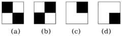
图4为本发明中用于角点及定位参考点检测的四种模板示意图,且e=11。FIG. 4 is a schematic diagram of four templates used for detection of corner points and positioning reference points in the present invention, and e=11.
具体实施方式Detailed ways
下面将结合附图对本发明的技术方案做进一步的详细说明。The technical solutions of the present invention will be further described in detail below in conjunction with the accompanying drawings.
本发明在于提供一种基于立式标靶的车载单目摄像头测距测高方法,主要是针对在车载单目摄像头已经检测到路面物体的情况下,计算物体高度及其距本车距离。车辆前方障碍物等距离及测高为无人驾驶或辅助驾驶系统的防撞预警、路径规划及车辆分类、涵洞桥梁通过性检测等的重要参数信息,具有较强的工程应用价值。本发明提供的方法只需一个摄像头则可实现单目测距及测高,而且具有较高的测量精度,操作简单可行。The present invention provides a method for measuring distance and height of a vehicle-mounted monocular camera based on a vertical target, which is mainly aimed at calculating the height of the object and its distance from the vehicle when the vehicle-mounted monocular camera has detected a road object. The equidistance and height measurement of obstacles in front of the vehicle are important parameter information for collision avoidance warning, path planning and vehicle classification, culvert bridge passability detection, etc. of unmanned or assisted driving systems, and have strong engineering application value. The method provided by the invention can realize monocular distance measurement and height measurement with only one camera, has high measurement accuracy, and is simple and feasible to operate.
本发明提供的方法不需要对摄像头进行标定,避免了标定的内外部参数误差对测量的影响,也不需要多次放置参照物或长距离测量,减少了误差产生的可能性,使得测量精度足以满足智能车环境感知系统对测距及测高的精度及实时性要求。本发明将立式标靶放置于摄像头正前方的合适位置后,采集一次图像,对感兴趣区进行了分块的自适应二值化处理,立式标靶的示意图如图3所示;在感兴趣区内利用模板(a)和(b)搜索匹配的所有子图,得到感兴趣区内角点的候选点集CC,具体流程如图2所示,模板如图4所示;对候选点集CC进行聚类、筛选等操作后得到初始角点集A,利用参考点与点集A中纵坐标最大点的位置关系,最终补齐并定位所有角点;由于所有角点的高度及其与摄像头的水平距离都为已知,可以得到各角点的实际成像角度,并用分段直线拟合出了图像的纵坐标与实际成像角度之间的映射关系,最后利用障碍物等在图像上的底端与顶端像素值即可分别实现测距与测高。The method provided by the invention does not need to calibrate the camera, avoids the influence of calibration internal and external parameter errors on the measurement, does not need to place reference objects multiple times or measure long distances, reduces the possibility of errors, and makes the measurement accuracy sufficient Meet the accuracy and real-time requirements of the intelligent vehicle environment perception system for distance measurement and height measurement. In the present invention, after the vertical target is placed at a suitable position directly in front of the camera, an image is collected once, and the region of interest is subjected to block-based adaptive binarization processing. The schematic diagram of the vertical target is shown in Figure 3; Use the templates (a) and (b) in the region of interest to search all the matching subgraphs, and get the candidate point set CC of the corner points in the region of interest. The specific process is shown in Figure 2, and the template is shown in Figure 4; for the candidate points Set CC to perform clustering, screening and other operations to obtain the initial corner point set A, use the positional relationship between the reference point and the point with the largest vertical coordinate in point set A, and finally fill and locate all corner points; due to the height of all corner points and their The horizontal distance from the camera is known, and the actual imaging angle of each corner point can be obtained, and the mapping relationship between the vertical coordinate of the image and the actual imaging angle is fitted by a segmented straight line, and finally, obstacles are used on the image The distance measurement and height measurement can be realized respectively by the bottom and top pixel values.
所述的实际成像角度是指:摄像头光轴的侧向平面与被测物体离车体最近的底线交点,将其与摄像头光心相连呈直线,此直线与摄像头光心垂直于地面的直线之间的夹角。The actual imaging angle refers to: the intersection point of the lateral plane of the optical axis of the camera and the bottom line of the measured object closest to the car body, connecting it with the optical center of the camera to form a straight line, which is between the straight line and the optical center of the camera perpendicular to the ground angle between.
图1展示了本发明一种基于立式标靶的车载单目摄像头测距测高方法的完整步骤流程,该方法分为以下几个步骤:Fig. 1 has shown a kind of vehicle-mounted monocular camera distance measurement and height measurement method based on the vertical target of the present invention, and the method is divided into the following steps:
步骤101:将摄像头安装在车体上的合适位置,然后将立式标靶放置于摄像头正前方,且尽量靠近摄像头的同时,需满足摄像头采集的图像中必须包含立式标靶的最低角点,且角点总数大于8个,测量摄像头安装高度h及其与立式标靶靶面的水平距离D;Step 101: Install the camera at a suitable position on the car body, and then place the vertical target directly in front of the camera, and as close as possible to the camera, the lowest corner point of the vertical target must be included in the image collected by the camera , and the total number of corner points is greater than 8, measure the installation height h of the camera and the horizontal distance D from the vertical target surface;
步骤102:采集标靶图像,分辨率为mm*nn,设置图像坐标系:左上角点为坐标原点,水平向右为x轴正方向,垂直向下为y轴正方向。设置角点检测的感兴趣区:x方向为[mm/3-1,2*mm/3-1],y方向为[0,nn-1]。对感兴趣区进行分块,对每个块分别采用最大类间方差法进行自适应二值化处理,使感兴趣区内的图像转化为二值图像;Step 102: Collect target images with a resolution of mm*nn, and set the image coordinate system: the upper left corner point is the origin of the coordinates, horizontally to the right is the positive direction of the x-axis, and vertically downward is the positive direction of the y-axis. Set the ROI for corner detection: the x direction is [mm/3-1,2*mm/3-1], and the y direction is [0,nn-1]. The region of interest is divided into blocks, and the maximum inter-class variance method is used for each block to perform adaptive binarization processing, so that the image in the region of interest is converted into a binary image;
其中块的大小s*v可以依据图像感兴趣区的宽高进行调整,但一般情况下s*v大于50*50,小于150*150,单位是pixel。The size of the block s*v can be adjusted according to the width and height of the image region of interest, but in general, s*v is greater than 50*50 and less than 150*150, and the unit is pixel.
步骤103:在感兴趣区内分别利用模板(a)和(b)进行全搜索匹配,采用匹配法检测角点,得到标靶角点的候选点集CC={(x1,y1),(x2,y2),…,(xk,yk)},其中k为匹配的子图总数。此步骤的执行流程如图2所示;Step 103: Use the templates (a) and (b) to perform full search and matching in the region of interest, use the matching method to detect corner points, and obtain the candidate point set CC={(x1 ,y1 ), (x2 ,y2 ),…,(xk ,yk )}, where k is the total number of matched subgraphs. The execution flow of this step is shown in Figure 2;
如图2所示,本发明方法中匹配法检测角点分为以下几个步骤:As shown in Figure 2, the matching method detection corner point in the method of the present invention is divided into the following steps:
步骤201:初始化循环参数ii及jj,都设置为零;Step 201: initializing loop parameters ii and jj, both of which are set to zero;
步骤202:以(mm/3-1+jj,ii)为左上角点,在感兴趣区中扩展出与模板大小相同的待检测子图S;所述模板如图4所示,包括四种尺寸大小相同的模板,模板大小尺寸均为2e*2e,单位为pixel,但像素值各不相同。其中,e为正方形模板边长的一半,模板(a)中左上角及右下角的e*e个像素的像素值为0(黑色),其余为255(白色);模板(b)中右上角及左下角的e*e个像素的像素值为0(黑色),其余为255(白色);模板(c)中右上角e*e个像素的像素值为0(黑色),其余为255(白色);模板(d)中右下角e*e个像素的像素值为0(黑色),其余为255(白色);而且,其用途也不相同,搜索标靶图像中的角点时用到模板(a)和(b),搜索定位参考点时用到模板(c)和(d)。Step 202: Taking (mm/3-1+jj,ii) as the upper left corner point, expand the sub-image S to be detected with the same size as the template in the region of interest; the template is shown in Figure 4, including four For templates with the same size, the template size is 2e*2e, and the unit is pixel, but the pixel values are different. Among them, e is half of the side length of the square template, the pixel value of the e*e pixels in the upper left corner and the lower right corner of the template (a) is 0 (black), and the rest is 255 (white); the upper right corner of the template (b) and the pixel values of e*e pixels in the lower left corner are 0 (black), and the rest are 255 (white); the pixel values of e*e pixels in the upper right corner in the template (c) are 0 (black), and the rest are 255 ( white); the pixel value of the e*e pixels in the lower right corner of the template (d) is 0 (black), and the rest are 255 (white); moreover, its purpose is not the same, it is used when searching for corner points in the target image Templates (a) and (b), templates (c) and (d) are used when searching for reference points.
步骤203:计算子图S与模板的差值图像G;Step 203: Calculate the difference image G between the subgraph S and the template;
所述的差值图像是指对子图S和模板(a)图像在相同位置像素点的像素值求差,并取绝对值后所得到的图像,即当求差的两幅二值化图像对应像素点的像素值相等时,差值图像在对应像素点上的像素值为0(黑色),如果不相同,像素值为255(白色)。The difference image refers to the image obtained by calculating the difference between the pixel values of the sub-image S and the template (a) image at the same position pixel, and taking the absolute value, that is, the two binarized images when the difference is calculated When the pixel values of the corresponding pixel points are equal, the pixel value of the difference image at the corresponding pixel point is 0 (black), if not, the pixel value is 255 (white).
步骤204:对差值图像G中的每个白色像素点,进行如下处理:以该白色像素点为左上角点,沿向右和向下方向扩充为7像素×7像素大小的块,将该块作为统计单元,计算该块中白色像素点的密度M;Step 204: For each white pixel in the difference image G, perform the following processing: take the white pixel as the upper left corner point, expand it into a block with a size of 7 pixels×7 pixels along the right and downward directions, and then A block is used as a statistical unit to calculate the density M of white pixels in the block;
所述的密度M是指差值图像中以7像素×7像素大小的块为统计单元,其中像素值为255(白色)的像素点的个数gg除以像素点的总个数49,公式如下:The density M refers to the difference image with a block size of 7 pixels×7 pixels as the statistical unit, where the number gg of pixels with a pixel value of 255 (white) is divided by the total number of pixels 49, the formula as follows:
M=gg49 (1)M=gg49 (1)
步骤205:对所述的密度M进行如下判断:Step 205: Perform the following judgment on the density M:
(A)判断是否存在大于密度阈值的密度M,如果存在某个区域的密度M大于设定的密度阈值,则认为模板(a)不匹配,进入步骤(B);否则,进入步骤206;(A) Judging whether there is a density M greater than the density threshold, if the density M of a certain area is greater than the set density threshold, it is considered that the template (a) does not match, and enter step (B); otherwise, enter step 206;
(B)计算子图S与模板(b)差值图像,如果存在某个区域的密度M大于设定的密度阈值,则认为模板(b)不匹配,进入步骤207,否则,进入步骤206;(B) Calculate the difference image between the sub-image S and the template (b), if the density M of a certain area is greater than the set density threshold, it is considered that the template (b) does not match, and go to step 207, otherwise, go to step 206;
密度阈值设置为0.32,如果密度阈值过大就会将两幅有较大差异的图像认为匹配,增大了误匹配,反之,如果密度阈值过小就会把一些由于光线或路面不平造成标靶存在一定旋转角度而造成的小范围零散的不同点误判为不匹配。通过试验,本发明所设置的密度阈值可以实现较好的检测效果。The density threshold is set to 0.32. If the density threshold is too large, two images with large differences will be considered as matching, which will increase the mismatch. On the contrary, if the density threshold is too small, some targets caused by light or uneven road surface will be taken into consideration. A small range of scattered differences caused by a certain rotation angle is misjudged as a mismatch. Through experiments, the density threshold set by the present invention can achieve better detection effect.
步骤206:将子图S左上角点坐标(mm/3-1+jj,ii)存入候选点集CC中;Step 206: Store the coordinates (mm/3-1+jj,ii) of the upper left corner of the sub-image S into the candidate point set CC;
步骤207:将ii加1,判断ii是否大于nn-1-2e,如果大于进入步骤208,否则,返回步骤202;Step 207: add 1 to ii, judge whether ii is greater than nn-1-2e, if greater, enter step 208, otherwise, return to step 202;
步骤208:将jj加1,ii设为初始值0,判断jj是否大于mm/3-2e,如果大于则结束此模板的匹配,否则,返回步骤202;Step 208: add 1 to jj, set ii to an initial value of 0, judge whether jj is greater than mm/3-2e, if greater, end the matching of this template, otherwise, return to step 202;
步骤104:对候选点集CC中所有点进行聚类及筛选处理;Step 104: clustering and screening all points in the candidate point set CC;
由于感兴趣区内的背景图像中可能也会存在与模板(a)和(b)相匹配的子图,所以为了剔除不是标靶角点处的候选点,需要进行聚类及筛选处理。Since there may also be subimages matching the templates (a) and (b) in the background image in the ROI, clustering and screening are required to eliminate candidate points that are not at the corners of the target.
聚类:首先将候选点集CC中所有的点进行分类处理,此过程为:分别计算第一个点与第二个点的横坐标之差值及纵坐标之差值,如果两个差值同时小于阈值T1则将这两个点记为同一个小类w1,否则将这两个点分别记为两个小类w1和w2;然后逐点计算候选点集CC中其它点与已经分为小类的所有点的横坐标之差值及纵坐标之差值,如果与小类中某点的两个差值同时小于阈值T1,则将待分类点与该小类的点记为同一个小类,否则认为都不属于已经存在的类,则将增加一个新的小类。假设总共分成了g小类,则小类的集W={w1,w2,…,wg}。分别计算各小类的中心点坐标(xwi,ywi)(i=1,2,…,g),将任意中心点横坐标之差值小于阈值T1的小类记为同一个大类;Clustering: First, classify all the points in the candidate point set CC. This process is to calculate the difference between the abscissa and the ordinate of the first point and the second point respectively. If the two differences If it is smaller than the threshold T1 at the same time, these two points will be recorded as the same small class w1 , otherwise these two points will be recorded as two small classes w1 and w2 respectively; The difference between the abscissa and the ordinate of all points that have been classified into subclasses, if the two differences with a point in the subclass are less than the threshold T1 at the same time, the point to be classified and the point of the subclass Recorded as the same subclass, otherwise it is considered that they do not belong to the existing class, and a new subclass will be added. Suppose it is divided into g small classes in total, then the set of small classes W={w1 ,w2 ,…,wg }. Calculate the center point coordinates (xwi , ywi ) (i=1,2,...,g) of each sub-category separately, and record the sub-categories whose difference in abscissa of any center point is less than the threshold T1 as the same major class ;
所述的计算个各小类中心点坐标是指将小类内所有点的横、纵坐标分别相加,再除以小类中点总的个数得到的x、y值作为此小类的中心点横、纵坐标值。The described calculation of the center point coordinates of each small class refers to adding the horizontal and vertical coordinates of all points in the small class respectively, and then dividing the x and y values obtained by the total number of points in the small class as the value of the small class. Center point abscissa and ordinate values.
筛选:由于标靶垂直于地面,而摄像头平行安装,在感兴趣区内标靶的角点的连线应基本竖直,横坐标之差值应小于阈值T1,则应属于一个大类。而且由于属于同一大类的误匹配点小类相对于属于同一大类的角点处小类,数量较少,所以保留包含小类数目最多的大类,剔除其他大类,并将保留下来的小类的中心点坐标在x和y方向上分别加上模板宽度和高度的一半e,存为初始角点集A={(xa1,ya1),(xa2,ya2),…,(xaj,yaj)},其中j为保留下来的小类的个数,而且初始角点集A中各点的顺序是以ya1,ya2,…,yaj值从大到小排列。Screening: Since the target is perpendicular to the ground and the camera is installed in parallel, the line connecting the corners of the target in the ROI should be basically vertical, and the difference in abscissa should be less than the threshold T1 , which should belong to a large category. And because the number of mis-matching point subcategories belonging to the same category is relatively small compared with the corner subcategories belonging to the same category, the category containing the largest number of subcategories is retained, other categories are eliminated, and the remaining ones are retained. The coordinates of the center point of the small class are added to the x and y directions by adding half e of the width and height of the template, and stored as the initial corner point set A={(xa1 ,ya1 ),(xa2 ,ya2 ),…, (xaj ,yaj )}, where j is the number of retained small classes, and the order of each point in the initial corner point set A is ya1 , ya2 ,…,yaj values are arranged from large to small .
步骤105:在初始角点集A中搜索出最大横坐标值xmax,利用模板(c)在横坐标小于xmax-e的感兴趣区内从上至下、从右至左搜索匹配的子图,一旦搜索到,则停止搜索。假设搜索到匹配的子图左上角点为(xf,yf),则角点的参考间隔ss=xmax-(xf+e),再利用模板(d)在点(xf,yf)左下方感兴趣区内从上至下、从右至左搜索匹配的子图,一旦搜索到,则停止搜索,记录匹配的子图左上角点为(xj,yj);Step 105: Search for the maximum abscissa value xmax in the initial corner point set A, and usethe template (c) to search for matching sub Graph, once searched, stop searching. Assuming that the upper left corner point of the matched subgraph is (xf , yf ), then the reference interval of the corner point ss=xmax -(xf +e), and then use the template (d) at the point (xf , yf ) Search the matching subgraph from top to bottom and from right to left in the lower left ROI, once found, stop searching, and record the upper left corner point of the matching subgraph as (xj , yj );
此次模板匹配法检测定位参考点的过程包括匹配模板(c)和匹配模板(d)两部分,在匹配模板(c)时,在x方向[mm/3-1,xmax-2*e],y方向[0,nn-1-2*e]区域内,按照从上至下、从右至左的顺序逐点搜索,并进行匹配检测。方法是将搜索点作为左上角点,扩展出与模板大小相同的待检测子图S;然后计算子图S与模板(c)的差值图像G;最后将差值图像G中的每个白色像素点扩充为7像素×7像素大小的块,计算所有块中白色像素点的密度M,如果存在某个块的密度M大于设定的密度阈值则认为此子图S与模板(c)不匹配,继续搜索下一点作为左上角点进行检测,否则认为匹配,结束搜索。匹配模板(d)时,搜索区域改为x方向[mm/3-1,xf-2*e],y方向[yf+2*e,nn-1-2*e],同样按照从上至下、从右至左的顺序逐点搜索,并进行匹配检测。检测过程与模板(c)相同。The process of detecting and positioning reference points by the template matching method includes two parts: matching template (c) and matching template (d). When matching template (c), in the x direction [mm/3-1, xmax -2*e ], in the [0,nn-1-2*e] area in the y direction, search point by point in the order from top to bottom and from right to left, and perform matching detection. The method is to use the search point as the upper left corner point to expand the sub-image S to be detected with the same size as the template; then calculate the difference image G between the sub-image S and the template (c); finally, each white in the difference image G The pixels are expanded to a block with a size of 7 pixels×7 pixels, and the density M of white pixels in all blocks is calculated. If there is a block whose density M is greater than the set density threshold, it is considered that this sub-image S is not consistent with the template (c). Match, continue to search for the next point as the upper left corner point for detection, otherwise consider it a match, and end the search. When matching the template (d), the search area is changed to [mm/3-1, xf -2*e] in the x direction and [yf +2*e, nn-1-2*e] in the y direction. Search point by point in order from top to bottom and from right to left, and perform matching detection. The detection process is the same as template (c).
步骤106:搜索完毕后,判断是否存在步骤105的两个定位参考点(xf,yf)和(xj,yj),如果存在进入步骤107;否则返回步骤101;Step 106: After the search is completed, judge whether there are two positioning reference points (xf , yf ) and (xj , yj ) in step 105, and if so, go to step 107; otherwise, return to step 101;
其中定位参考点(xf,yf)有可能是图3所示的参考点①或者参考点②,因为如果标靶完全竖直或存在顺时针旋转,那首先搜索到的是参考点①,否则是参考点②,而(xj,yj)为参考点③。搜索定位参考点的目的为:(1)由于对立式标靶的靶面进行分析后发现在竖直角点集的左侧只有两处满足模板(c)的特征,而其左下方只有一处满足模板(d)的特征,所以搜索定位参考点可进一步确认检测到的初始角点集A的正确性;(2)由于参考点③及其与角点相对位置的唯一性,可以利用它对各角点进行定位。所述参考点①为从下至上第六个角点左侧的一个具有明显灰度分布特点的点,其右上角的e*e个像素的像素值为0(黑色),其余为255(白色);参考点②为第四个角点左侧与参考点①具有相同灰度分布的点;参考点③为第二个角点左侧大概两倍间隔处,灰度分布为右下角的e*e个像素的像素值为0(黑色),其余为255(白色)的点。The positioning reference point (xf , yf ) may be the reference point ① or the
所以,如果由于摄像机安装或标靶放置不当,在步骤105中没有检测到两个定位参考点(xf,yf)和(xj,yj),则无法判断初始角点集A的准确性,更无法定位,则需要返回101重新开始。Therefore, if the two positioning reference points (xf , yf ) and (xj , yj ) are not detected in step 105 due to improper camera installation or target placement, the accuracy of the initial corner set A cannot be judged. sex, more can not be located, you need to return to 101 to start again.
步骤107:将初始角点集A中纵坐标最大值ya1与yj进行比较,如果ya1-yj为ss的3倍左右,认为点(xa1,ya1)为标靶最低角点,否则,将点(xmax,yj+ss*3)作为标靶的最低角点;然后将角点补充完整,并得到角点集C={(xc1,yc1),(xc2,yc2),…,(xcn,ycn)},其中n表示角点集中标靶角点总数,且C中各点的顺序也以y值从大到小排列,最后运用openCV中的cvFindCornerSubPix()函数,以角点集C为基准将其更新为亚像素级角点集B={(xb1,yb1),(xb2,yb2),…,(xbn,ybn)};Step 107: Compare the maximum value ya1 of the ordinate in the initial corner point set A with yj , if ya1 -yj is about 3 times of ss, consider the point (xa1 , ya1 ) to be the lowest corner point of the target , otherwise, take the point (xmax ,yj +ss*3) as the lowest corner point of the target; then complete the corner points and get the corner point set C={(xc1 ,yc1 ),(xc2 ,yc2 ),…,(xcn ,ycn )}, where n represents the total number of target corner points in the corner point set, and the order of each point in C is also arranged in descending order of the y value, and finally use the openCV The cvFindCornerSubPix() function updates the corner point set C to a sub-pixel level corner point set B={(xb1 ,yb1 ),(xb2 ,yb2 ),…,(xbn ,ybn ) };
其中,将角点补充完整的过程为:如果点(xa1,ya1)为标靶最低角点,则依次计算初始角点集A中相邻点纵坐标值之差yaii-ya(ii+1),当差值为ss的t倍左右,则需要在点集A的第ii个点与第ii+1个点之间补充上t-1个点(如果t为1则不需要在这两点间补充),坐标分别为(xaii,yaii-jj*ss)(jj=1,…,t-1),当搜索到A中最后一个点(xaj,yaj)时,以yaj作为差值进行计算;如果点(xmax,yj+ss*2)为标靶最低角点,那么还需要计算差值yj+ss*2-ya1,以同样的方法将点(xmax,yj+ss*2)与点(xa1,ya1)之间的角点补充完整。Among them, the process of completing the corner points is: if the point (xa1 , ya1 ) is the lowest corner point of the target, then calculate the difference yaii -ya( ii+1) , when the difference is about t times of ss, you need to add t-1 points between point ii and point ii+1 of point set A (if t is 1, it is not required Supplement between these two points), the coordinates are (xaii ,yaii -jj*ss) (jj=1,...,t-1), when the last point (xaj ,yaj ) in A is searched , calculate with yaj as the difference; if the point (xmax ,yj +ss*2) is the lowest corner point of the target, then also need to calculate the difference yj +ss*2-ya1 , in the same way Complete the corner point between point (xmax ,yj +ss*2) and point (xa1 ,ya1 ).
步骤108:图像中n个角点的高度集HH={h1,h2,…,hn}={1.00,1.05,…,1.00+(n-1)*0.05},然后利用参数h和D,通过式(2)计算得到各角点的实际成像角度集Q={q1,q2,…,qn},其中各角度值与亚像素级角点集B的纵坐标{yb1,yb2,…,ybn}按顺序一一对应,得到映射点集P={(yb1,q1),(yb2,q2),…,(ybn,qn)},以直线拟合映射点集内相邻两点,得到相邻点映射关系集F={f1,f2,…,fn-1},如式(3)所示;Step 108: The height set of n corner points in the image HH={h1 ,h2 ,…,hn }={1.00,1.05,…,1.00+(n-1)*0.05}, then use the parameters h and D. Calculate the actual imaging angle set Q={q1 ,q2 ,…,qn } of each corner point through formula (2), where each angle value is related to the vertical coordinate {yb1 of the sub-pixel level corner point set B ,yb2 ,…,ybn } correspond one-to-one in order, and the mapping point set P={(yb1 ,q1 ),(yb2 ,q2 ),…,(ybn ,qn )} is obtained. A straight line fits two adjacent points in the mapping point set to obtain the adjacent point mapping relationship set F={f1 ,f2 ,…,fn-1 }, as shown in formula (3);
qii=tan-1[D/(h-hii)] (2)qii =tan-1 [D/(hhii )] (2)
其中,ii=1,…,n。Among them, ii=1,...,n.
其中,ii=1,…,n-1。Among them, ii=1,...,n-1.
步骤109:在实时测距过程中,将通过障碍物检测算法得到的障碍物底部y方向坐标yz作为参数输入,首先判断出yz所属的映射关系fii(0<ii<n),利用fii的直线方程计算yz对应的实际成像角度qZ,然后以qZ作为输入通过测距方程(4)计算障碍物的距离Lz;Step 109: In the process of real-time distance measurement, the y-direction coordinate yz of the bottom of the obstacle obtained by the obstacle detection algorithm is input as a parameter, and the mapping relationship fii (0<ii<n) to which yz belongs is firstly judged, using The straight line equation of fii calculates the actual imaging angle qZ corresponding to yz , and then uses qZ as input to calculate the distance Lz of the obstacle through the ranging equation (4);
Lz=h·tanqz (4)Lz = h·tanqz (4)
其中,当yz小于等于yb2时,选择映射关系f1计算实际成像角度qZ;当yz大于等于yb(n-1)时,选择映射关系fn-1计算实际成像角度qZ;其他情况下,首先搜索到yz所在区间,即Among them, when yz is less than or equal to yb2 , select the mapping relationship f1 to calculate the actual imaging angle qZ ; when yz is greater than or equal to yb(n-1) , select the mapping relationship fn-1 to calculate the actual imaging angle qZ ; In other cases, first search for the interval where yz is located, namely
ybii<yz<yb(ii+1),然后选择映射关系fii计算实际成像角度qZ。ybii <yz <yb(ii+1) , and then select the mapping relationship fii to calculate the actual imaging angle qZ .
步骤110:根据系统需要判断是否需要测量障碍物的高度,如果需要判断则继续步骤111;否则结束此障碍物的测距;Step 110: Determine whether the height of the obstacle needs to be measured according to the needs of the system, and if so, proceed to step 111; otherwise, end the distance measurement of the obstacle;
由于在不同系统中,需要的信息不同,例如在防撞预警中可能不需要高度信息,但在桥梁涵洞等通过性检测时必须得到高度信息,所以需要判读系统是否需要高度信息。Since different systems require different information, for example, height information may not be required in collision avoidance warning, but height information must be obtained in passing inspections such as bridges and culverts, so it is necessary to judge whether the system needs height information.
步骤111:首先利用测距同样的方法判断障碍物检测算法得到的障碍物顶部y方向坐标yd所属的映射关系fii(0<ii<n),利用fii的直线方程计算yd对应的实际成像角度qd,然后以qd和障碍物距离Lz作为输入通过测高方程(5)计算障碍物等的高度Hz。Step 111: first use the same method of distance measurement to judge the mapping relationship fii (0<ii<n) to which the coordinate yd of the top of the obstacle in the y direction obtained by the obstacle detection algorithm belongs, and use the straight line equation of fii to calculate the corresponding value of yd The actual imaging angle qd , and then use qd and the obstacle distance Lz as input to calculate the height Hz of obstacles etc. through the altimetry equation (5).
Hz=h-a·Lz·tan(|90°-qd|) (5)Hz = ha Lz tan(|90°-qd |) (5)
其中,当qd≥90°时a取-1,当qd<90°时a取1。Wherein, a takes -1 when qd ≥ 90°, and takes 1 when qd < 90°.
表5为利用此方法测距的实验结果及误差,选用的图像分辨率为752*480,摄像头安装高度为1.32m,标靶与摄像头的水平距离为1.8m,从表5可以看出,此方法总体误差很小,一般小于1%,虽然在80m时可能由于路面平整度或障碍物检测精度等影响,误差达到2.3029%,但也已经远远满足智能车辆的测距精度要求。Table 5 shows the experimental results and errors of distance measurement using this method. The selected image resolution is 752*480, the installation height of the camera is 1.32m, and the horizontal distance between the target and the camera is 1.8m. It can be seen from Table 5 that this The overall error of the method is very small, generally less than 1%. Although the error may reach 2.3029% at 80m due to the influence of road surface roughness or obstacle detection accuracy, it has far met the ranging accuracy requirements of intelligent vehicles.
表6为利用此方法测高的实验结果及误差,图像分辨率、摄像头高度及标靶放置位置与测距实验相同,测高的实验对象是身高为1.77m的人,从表6可以看出,误差均保持在4%以内。由于测高会受到测距误差、障碍物检测及图像畸变等影响,所以测高误差一般比测距误差大,但可以基本满足车辆在桥梁、涵洞等通过性检测的要求。Table 6 shows the experimental results and errors of height measurement using this method. The image resolution, camera height and target placement are the same as those in the distance measurement experiment. The experimental object of height measurement is a person with a height of 1.77m. , the error is kept within 4%. Since height measurement will be affected by distance measurement error, obstacle detection and image distortion, the height measurement error is generally larger than the distance measurement error, but it can basically meet the requirements of vehicle passability detection on bridges and culverts.
表5应用本发明提供的方法进行测距的实验结果及误差Table 5 applies the method provided by the invention to carry out the experimental result and error of ranging
表6应用本发明提供的方法进行测高的实验结果及误差Table 6 applies the method provided by the invention to carry out the experimental result and error of altimetry
Claims (8)
Translated fromChinesePriority Applications (1)
| Application Number | Priority Date | Filing Date | Title |
|---|---|---|---|
| CN201310445576.4ACN103487034B (en) | 2013-09-26 | 2013-09-26 | Method for measuring distance and height by vehicle-mounted monocular camera based on vertical type target |
Applications Claiming Priority (1)
| Application Number | Priority Date | Filing Date | Title |
|---|---|---|---|
| CN201310445576.4ACN103487034B (en) | 2013-09-26 | 2013-09-26 | Method for measuring distance and height by vehicle-mounted monocular camera based on vertical type target |
Publications (2)
| Publication Number | Publication Date |
|---|---|
| CN103487034Atrue CN103487034A (en) | 2014-01-01 |
| CN103487034B CN103487034B (en) | 2015-07-15 |
Family
ID=49827449
Family Applications (1)
| Application Number | Title | Priority Date | Filing Date |
|---|---|---|---|
| CN201310445576.4AExpired - Fee RelatedCN103487034B (en) | 2013-09-26 | 2013-09-26 | Method for measuring distance and height by vehicle-mounted monocular camera based on vertical type target |
Country Status (1)
| Country | Link |
|---|---|
| CN (1) | CN103487034B (en) |
Cited By (20)
| Publication number | Priority date | Publication date | Assignee | Title |
|---|---|---|---|---|
| CN105203034A (en)* | 2015-07-29 | 2015-12-30 | 四川大学 | Height and area measurement method based on monocular camera three-dimensional distance measurement model |
| CN105241424A (en)* | 2015-09-25 | 2016-01-13 | 小米科技有限责任公司 | Indoor positioning method and intelligent management apparatus |
| CN105405117A (en)* | 2015-10-16 | 2016-03-16 | 凌云光技术集团有限责任公司 | Angular point extraction method based on image contour and angular point extraction device |
| CN105539311A (en)* | 2016-01-29 | 2016-05-04 | 深圳市美好幸福生活安全系统有限公司 | Method and device for installing camera |
| CN106023271A (en)* | 2016-07-22 | 2016-10-12 | 武汉海达数云技术有限公司 | Method and device for extracting center coordinates of target |
| CN106504287A (en)* | 2016-10-19 | 2017-03-15 | 大连民族大学 | Monocular vision object space alignment system based on template |
| CN106981082A (en)* | 2017-03-08 | 2017-07-25 | 驭势科技(北京)有限公司 | Vehicle-mounted camera scaling method, device and mobile unit |
| CN107003409A (en)* | 2015-01-27 | 2017-08-01 | 宝马股份公司 | The measurement of size on the surface |
| CN107305632A (en)* | 2017-02-16 | 2017-10-31 | 武汉极目智能技术有限公司 | Destination object distance measurement method and system based on monocular computer vision technique |
| CN108445496A (en)* | 2018-01-02 | 2018-08-24 | 北京汽车集团有限公司 | Ranging caliberating device and method, distance-measuring equipment and distance measuring method |
| CN108931205A (en)* | 2018-07-25 | 2018-12-04 | 杭州非白三维科技有限公司 | A kind of 3 D scanning system and scan method |
| CN109215083A (en)* | 2017-07-06 | 2019-01-15 | 华为技术有限公司 | Method and device for calibrating external parameters of vehicle-mounted sensors |
| CN109959919A (en)* | 2017-12-22 | 2019-07-02 | 比亚迪股份有限公司 | Vehicle and monocular camera ranging method and device |
| CN111241224A (en)* | 2020-01-10 | 2020-06-05 | 福瑞泰克智能系统有限公司 | Method, system, computer device and storage medium for target distance estimation |
| CN112651359A (en)* | 2020-12-30 | 2021-04-13 | 深兰科技(上海)有限公司 | Obstacle detection method, obstacle detection device, electronic apparatus, and storage medium |
| CN112907675A (en)* | 2019-11-19 | 2021-06-04 | 浙江商汤科技开发有限公司 | Calibration method, device, system, equipment and storage medium of image acquisition equipment |
| CN113041578A (en)* | 2021-02-24 | 2021-06-29 | 南京师范大学 | Robot automatic ball picking method based on morphological characteristics and monocular measurement |
| CN113218361A (en)* | 2020-01-21 | 2021-08-06 | 上海汽车集团股份有限公司 | Camera ranging method and device |
| CN114693803A (en)* | 2022-03-17 | 2022-07-01 | 广州小鹏自动驾驶科技有限公司 | Parameter calibration method and device, vehicle and storage medium |
| CN117928471A (en)* | 2024-03-18 | 2024-04-26 | 东莞潜星电子科技有限公司 | Vehicle-mounted monocular camera distance and height measurement equipment and method based on vertical targets |
Citations (3)
| Publication number | Priority date | Publication date | Assignee | Title |
|---|---|---|---|---|
| DE10338884A1 (en)* | 2003-08-23 | 2005-03-17 | Valeo Schalter Und Sensoren Gmbh | Vehicle, especially motor vehicle, object separation measurement method is based on imaging of the object using a 2D monocular camera and then determining its separation distance by analysis of its light intensity distribution |
| CN101038165A (en)* | 2007-02-16 | 2007-09-19 | 北京航空航天大学 | Vehicle environment based on two eyes visual and distance measuring system |
| CN101055177A (en)* | 2007-05-30 | 2007-10-17 | 北京航空航天大学 | Double surface drone based flow type tri-dimensional visual measurement splicing method |
- 2013
- 2013-09-26CNCN201310445576.4Apatent/CN103487034B/ennot_activeExpired - Fee Related
Patent Citations (3)
| Publication number | Priority date | Publication date | Assignee | Title |
|---|---|---|---|---|
| DE10338884A1 (en)* | 2003-08-23 | 2005-03-17 | Valeo Schalter Und Sensoren Gmbh | Vehicle, especially motor vehicle, object separation measurement method is based on imaging of the object using a 2D monocular camera and then determining its separation distance by analysis of its light intensity distribution |
| CN101038165A (en)* | 2007-02-16 | 2007-09-19 | 北京航空航天大学 | Vehicle environment based on two eyes visual and distance measuring system |
| CN101055177A (en)* | 2007-05-30 | 2007-10-17 | 北京航空航天大学 | Double surface drone based flow type tri-dimensional visual measurement splicing method |
Non-Patent Citations (2)
| Title |
|---|
| 姜岩等: "基于角点特征的立体视觉车辆环境感知系统研究", 《机械工程学报》* |
| 徐国艳等: "车辆视频检测感兴趣区域确定算法", 《北京航空航天大学学报》* |
Cited By (35)
| Publication number | Priority date | Publication date | Assignee | Title |
|---|---|---|---|---|
| CN107003409A (en)* | 2015-01-27 | 2017-08-01 | 宝马股份公司 | The measurement of size on the surface |
| CN105203034A (en)* | 2015-07-29 | 2015-12-30 | 四川大学 | Height and area measurement method based on monocular camera three-dimensional distance measurement model |
| CN105203034B (en)* | 2015-07-29 | 2018-07-17 | 四川大学 | A kind of survey height survey area method based on monocular cam three-dimensional ranging model |
| CN105241424B (en)* | 2015-09-25 | 2017-11-21 | 小米科技有限责任公司 | Indoor orientation method and intelligent management apapratus |
| CN105241424A (en)* | 2015-09-25 | 2016-01-13 | 小米科技有限责任公司 | Indoor positioning method and intelligent management apparatus |
| CN105405117A (en)* | 2015-10-16 | 2016-03-16 | 凌云光技术集团有限责任公司 | Angular point extraction method based on image contour and angular point extraction device |
| CN105405117B (en)* | 2015-10-16 | 2018-07-03 | 凌云光技术集团有限责任公司 | Angular Point Extracting Method and device based on image outline |
| CN105539311A (en)* | 2016-01-29 | 2016-05-04 | 深圳市美好幸福生活安全系统有限公司 | Method and device for installing camera |
| CN105539311B (en)* | 2016-01-29 | 2017-12-05 | 深圳市美好幸福生活安全系统有限公司 | The installation method and erecting device of a kind of camera |
| CN106023271A (en)* | 2016-07-22 | 2016-10-12 | 武汉海达数云技术有限公司 | Method and device for extracting center coordinates of target |
| CN106023271B (en)* | 2016-07-22 | 2018-12-11 | 武汉海达数云技术有限公司 | A kind of target center coordinate extraction method and device |
| CN106504287A (en)* | 2016-10-19 | 2017-03-15 | 大连民族大学 | Monocular vision object space alignment system based on template |
| CN106504287B (en)* | 2016-10-19 | 2019-02-15 | 大连民族大学 | Template-based monocular vision target space localization system |
| CN107305632A (en)* | 2017-02-16 | 2017-10-31 | 武汉极目智能技术有限公司 | Destination object distance measurement method and system based on monocular computer vision technique |
| CN107305632B (en)* | 2017-02-16 | 2020-06-12 | 武汉极目智能技术有限公司 | Monocular computer vision technology-based target object distance measuring method and system |
| CN106981082A (en)* | 2017-03-08 | 2017-07-25 | 驭势科技(北京)有限公司 | Vehicle-mounted camera scaling method, device and mobile unit |
| CN106981082B (en)* | 2017-03-08 | 2020-04-17 | 驭势科技(北京)有限公司 | Vehicle-mounted camera calibration method and device and vehicle-mounted equipment |
| CN109215083A (en)* | 2017-07-06 | 2019-01-15 | 华为技术有限公司 | Method and device for calibrating external parameters of vehicle-mounted sensors |
| US11670193B2 (en) | 2017-07-06 | 2023-06-06 | Huawei Technologies Co., Ltd. | Extrinsic parameter of on-board sensor |
| CN109959919B (en)* | 2017-12-22 | 2021-03-26 | 比亚迪股份有限公司 | Automobile and monocular camera ranging method and device |
| CN109959919A (en)* | 2017-12-22 | 2019-07-02 | 比亚迪股份有限公司 | Vehicle and monocular camera ranging method and device |
| CN108445496A (en)* | 2018-01-02 | 2018-08-24 | 北京汽车集团有限公司 | Ranging caliberating device and method, distance-measuring equipment and distance measuring method |
| CN108931205A (en)* | 2018-07-25 | 2018-12-04 | 杭州非白三维科技有限公司 | A kind of 3 D scanning system and scan method |
| CN108931205B (en)* | 2018-07-25 | 2024-04-09 | 杭州非白三维科技有限公司 | Three-dimensional scanning system and scanning method |
| CN112907675B (en)* | 2019-11-19 | 2022-05-24 | 浙江商汤科技开发有限公司 | Calibration method, device, system, equipment and storage medium of image acquisition equipment |
| CN112907675A (en)* | 2019-11-19 | 2021-06-04 | 浙江商汤科技开发有限公司 | Calibration method, device, system, equipment and storage medium of image acquisition equipment |
| CN111241224A (en)* | 2020-01-10 | 2020-06-05 | 福瑞泰克智能系统有限公司 | Method, system, computer device and storage medium for target distance estimation |
| CN113218361A (en)* | 2020-01-21 | 2021-08-06 | 上海汽车集团股份有限公司 | Camera ranging method and device |
| CN113218361B (en)* | 2020-01-21 | 2023-02-17 | 上海汽车集团股份有限公司 | Camera ranging method and device |
| CN112651359A (en)* | 2020-12-30 | 2021-04-13 | 深兰科技(上海)有限公司 | Obstacle detection method, obstacle detection device, electronic apparatus, and storage medium |
| CN113041578B (en)* | 2021-02-24 | 2022-02-11 | 南京师范大学 | Robot automatic ball picking method based on morphological characteristics and monocular measurement |
| CN113041578A (en)* | 2021-02-24 | 2021-06-29 | 南京师范大学 | Robot automatic ball picking method based on morphological characteristics and monocular measurement |
| CN114693803A (en)* | 2022-03-17 | 2022-07-01 | 广州小鹏自动驾驶科技有限公司 | Parameter calibration method and device, vehicle and storage medium |
| CN117928471A (en)* | 2024-03-18 | 2024-04-26 | 东莞潜星电子科技有限公司 | Vehicle-mounted monocular camera distance and height measurement equipment and method based on vertical targets |
| CN117928471B (en)* | 2024-03-18 | 2024-08-09 | 东莞潜星电子科技有限公司 | Vehicle-mounted monocular camera distance and height measurement equipment and method based on vertical targets |
Also Published As
| Publication number | Publication date |
|---|---|
| CN103487034B (en) | 2015-07-15 |
Similar Documents
| Publication | Publication Date | Title |
|---|---|---|
| CN103487034B (en) | Method for measuring distance and height by vehicle-mounted monocular camera based on vertical type target | |
| CN103499337B (en) | Vehicle-mounted monocular camera distance and height measuring device based on vertical target | |
| CN109100741B (en) | A target detection method based on 3D lidar and image data | |
| CN109064495B (en) | Bridge deck vehicle space-time information acquisition method based on fast R-CNN and video technology | |
| CN110031829B (en) | An accurate ranging method for targets based on monocular vision | |
| CN109084724A (en) | A kind of deep learning barrier distance measuring method based on binocular vision | |
| CN114359181B (en) | Intelligent traffic target fusion detection method and system based on image and point cloud | |
| CN110307791B (en) | Calculation method of vehicle length and speed based on 3D vehicle bounding box | |
| CN106951879A (en) | Multi-feature fusion vehicle detection method based on camera and millimeter wave radar | |
| CN101750049A (en) | Monocular vision vehicle distance measuring method based on road and vehicle information | |
| JP7050763B2 (en) | Detection of objects from camera images | |
| CN111272139B (en) | A vehicle length measurement method based on monocular vision | |
| CN107796373B (en) | Distance measurement method based on monocular vision of front vehicle driven by lane plane geometric model | |
| CN107463890A (en) | A kind of Foregut fermenters and tracking based on monocular forward sight camera | |
| Tsai et al. | Horizontal roadway curvature computation algorithm using vision technology | |
| CN103177584B (en) | Vehicle speed detection method based on enumeration probe | |
| CN113111707B (en) | Front car detection and ranging method based on convolutional neural network | |
| CN115267756A (en) | Monocular real-time distance measurement method based on deep learning target detection | |
| CN110728720B (en) | Method, apparatus, device and storage medium for camera calibration | |
| CN116503818A (en) | A multi-lane vehicle speed detection method and system | |
| Zhu et al. | Fine-grained identification of vehicle loads on bridges based on computer vision | |
| CN113465572A (en) | Monocular distance measurement method and system based on camera imaging geometric relation | |
| CN115457130A (en) | Electric vehicle charging port detection and positioning method based on depth key point regression | |
| CN116148842A (en) | Vision and imaging millimeter wave radar point cloud fusion method, system and equipment | |
| CN114858134A (en) | Monocular camera ranging method based on target position information and readable storage medium |
Legal Events
| Date | Code | Title | Description |
|---|---|---|---|
| C06 | Publication | ||
| PB01 | Publication | ||
| C10 | Entry into substantive examination | ||
| SE01 | Entry into force of request for substantive examination | ||
| C14 | Grant of patent or utility model | ||
| GR01 | Patent grant | ||
| CF01 | Termination of patent right due to non-payment of annual fee | Granted publication date:20150715 Termination date:20180926 | |
| CF01 | Termination of patent right due to non-payment of annual fee |