CN103476312A - Vacuum cleaner dust container and vacuum cleaner - Google Patents
Vacuum cleaner dust container and vacuum cleanerDownload PDFInfo
- Publication number
- CN103476312A CN103476312ACN2012800088859ACN201280008885ACN103476312ACN 103476312 ACN103476312 ACN 103476312ACN 2012800088859 ACN2012800088859 ACN 2012800088859ACN 201280008885 ACN201280008885 ACN 201280008885ACN 103476312 ACN103476312 ACN 103476312A
- Authority
- CN
- China
- Prior art keywords
- vacuum cleaner
- dust
- cover
- dust container
- collection chamber
- Prior art date
- Legal status (The legal status is an assumption and is not a legal conclusion. Google has not performed a legal analysis and makes no representation as to the accuracy of the status listed.)
- Granted
Links
Images


Classifications
- A—HUMAN NECESSITIES
- A47—FURNITURE; DOMESTIC ARTICLES OR APPLIANCES; COFFEE MILLS; SPICE MILLS; SUCTION CLEANERS IN GENERAL
- A47L—DOMESTIC WASHING OR CLEANING; SUCTION CLEANERS IN GENERAL
- A47L9/00—Details or accessories of suction cleaners, e.g. mechanical means for controlling the suction or for effecting pulsating action; Storing devices specially adapted to suction cleaners or parts thereof; Carrying-vehicles specially adapted for suction cleaners
- A47L9/10—Filters; Dust separators; Dust removal; Automatic exchange of filters
- A47L9/16—Arrangement or disposition of cyclones or other devices with centrifugal action
- A47L9/1616—Multiple arrangement thereof
- A47L9/1625—Multiple arrangement thereof for series flow
- A—HUMAN NECESSITIES
- A47—FURNITURE; DOMESTIC ARTICLES OR APPLIANCES; COFFEE MILLS; SPICE MILLS; SUCTION CLEANERS IN GENERAL
- A47L—DOMESTIC WASHING OR CLEANING; SUCTION CLEANERS IN GENERAL
- A47L5/00—Structural features of suction cleaners
- A47L5/12—Structural features of suction cleaners with power-driven air-pumps or air-compressors, e.g. driven by motor vehicle engine vacuum
- A47L5/22—Structural features of suction cleaners with power-driven air-pumps or air-compressors, e.g. driven by motor vehicle engine vacuum with rotary fans
- A47L5/36—Suction cleaners with hose between nozzle and casing; Suction cleaners for fixing on staircases; Suction cleaners for carrying on the back
- A47L5/362—Suction cleaners with hose between nozzle and casing; Suction cleaners for fixing on staircases; Suction cleaners for carrying on the back of the horizontal type, e.g. canister or sledge type
- A—HUMAN NECESSITIES
- A47—FURNITURE; DOMESTIC ARTICLES OR APPLIANCES; COFFEE MILLS; SPICE MILLS; SUCTION CLEANERS IN GENERAL
- A47L—DOMESTIC WASHING OR CLEANING; SUCTION CLEANERS IN GENERAL
- A47L9/00—Details or accessories of suction cleaners, e.g. mechanical means for controlling the suction or for effecting pulsating action; Storing devices specially adapted to suction cleaners or parts thereof; Carrying-vehicles specially adapted for suction cleaners
- A47L9/10—Filters; Dust separators; Dust removal; Automatic exchange of filters
- A47L9/106—Dust removal
- A47L9/108—Dust compression means
- A—HUMAN NECESSITIES
- A47—FURNITURE; DOMESTIC ARTICLES OR APPLIANCES; COFFEE MILLS; SPICE MILLS; SUCTION CLEANERS IN GENERAL
- A47L—DOMESTIC WASHING OR CLEANING; SUCTION CLEANERS IN GENERAL
- A47L9/00—Details or accessories of suction cleaners, e.g. mechanical means for controlling the suction or for effecting pulsating action; Storing devices specially adapted to suction cleaners or parts thereof; Carrying-vehicles specially adapted for suction cleaners
- A47L9/10—Filters; Dust separators; Dust removal; Automatic exchange of filters
- A47L9/16—Arrangement or disposition of cyclones or other devices with centrifugal action
- A47L9/1608—Cyclonic chamber constructions
- A—HUMAN NECESSITIES
- A47—FURNITURE; DOMESTIC ARTICLES OR APPLIANCES; COFFEE MILLS; SPICE MILLS; SUCTION CLEANERS IN GENERAL
- A47L—DOMESTIC WASHING OR CLEANING; SUCTION CLEANERS IN GENERAL
- A47L9/00—Details or accessories of suction cleaners, e.g. mechanical means for controlling the suction or for effecting pulsating action; Storing devices specially adapted to suction cleaners or parts thereof; Carrying-vehicles specially adapted for suction cleaners
- A47L9/10—Filters; Dust separators; Dust removal; Automatic exchange of filters
- A47L9/16—Arrangement or disposition of cyclones or other devices with centrifugal action
- A47L9/1616—Multiple arrangement thereof
- A47L9/1641—Multiple arrangement thereof for parallel flow
- A—HUMAN NECESSITIES
- A47—FURNITURE; DOMESTIC ARTICLES OR APPLIANCES; COFFEE MILLS; SPICE MILLS; SUCTION CLEANERS IN GENERAL
- A47L—DOMESTIC WASHING OR CLEANING; SUCTION CLEANERS IN GENERAL
- A47L9/00—Details or accessories of suction cleaners, e.g. mechanical means for controlling the suction or for effecting pulsating action; Storing devices specially adapted to suction cleaners or parts thereof; Carrying-vehicles specially adapted for suction cleaners
- A47L9/10—Filters; Dust separators; Dust removal; Automatic exchange of filters
- A47L9/16—Arrangement or disposition of cyclones or other devices with centrifugal action
- A47L9/1658—Construction of outlets
- A—HUMAN NECESSITIES
- A47—FURNITURE; DOMESTIC ARTICLES OR APPLIANCES; COFFEE MILLS; SPICE MILLS; SUCTION CLEANERS IN GENERAL
- A47L—DOMESTIC WASHING OR CLEANING; SUCTION CLEANERS IN GENERAL
- A47L9/00—Details or accessories of suction cleaners, e.g. mechanical means for controlling the suction or for effecting pulsating action; Storing devices specially adapted to suction cleaners or parts thereof; Carrying-vehicles specially adapted for suction cleaners
- A47L9/10—Filters; Dust separators; Dust removal; Automatic exchange of filters
- A47L9/16—Arrangement or disposition of cyclones or other devices with centrifugal action
- A47L9/1683—Dust collecting chambers; Dust collecting receptacles
- A—HUMAN NECESSITIES
- A47—FURNITURE; DOMESTIC ARTICLES OR APPLIANCES; COFFEE MILLS; SPICE MILLS; SUCTION CLEANERS IN GENERAL
- A47L—DOMESTIC WASHING OR CLEANING; SUCTION CLEANERS IN GENERAL
- A47L9/00—Details or accessories of suction cleaners, e.g. mechanical means for controlling the suction or for effecting pulsating action; Storing devices specially adapted to suction cleaners or parts thereof; Carrying-vehicles specially adapted for suction cleaners
- A47L9/10—Filters; Dust separators; Dust removal; Automatic exchange of filters
- A47L9/16—Arrangement or disposition of cyclones or other devices with centrifugal action
- A47L9/1691—Mounting or coupling means for cyclonic chamber or dust receptacles
- A—HUMAN NECESSITIES
- A47—FURNITURE; DOMESTIC ARTICLES OR APPLIANCES; COFFEE MILLS; SPICE MILLS; SUCTION CLEANERS IN GENERAL
- A47L—DOMESTIC WASHING OR CLEANING; SUCTION CLEANERS IN GENERAL
- A47L9/00—Details or accessories of suction cleaners, e.g. mechanical means for controlling the suction or for effecting pulsating action; Storing devices specially adapted to suction cleaners or parts thereof; Carrying-vehicles specially adapted for suction cleaners
- A47L9/10—Filters; Dust separators; Dust removal; Automatic exchange of filters
- A47L9/19—Means for monitoring filtering operation
- A—HUMAN NECESSITIES
- A47—FURNITURE; DOMESTIC ARTICLES OR APPLIANCES; COFFEE MILLS; SPICE MILLS; SUCTION CLEANERS IN GENERAL
- A47L—DOMESTIC WASHING OR CLEANING; SUCTION CLEANERS IN GENERAL
- A47L9/00—Details or accessories of suction cleaners, e.g. mechanical means for controlling the suction or for effecting pulsating action; Storing devices specially adapted to suction cleaners or parts thereof; Carrying-vehicles specially adapted for suction cleaners
- A47L9/32—Handles
- A47L9/327—Handles for suction cleaners with hose between nozzle and casing
Landscapes
- Engineering & Computer Science (AREA)
- Mechanical Engineering (AREA)
- Filters For Electric Vacuum Cleaners (AREA)
Abstract
Description
Translated fromChinese技术领域technical field
本申请涉及一种真空吸尘器灰尘容器以及一种具有至少一个旋流式灰尘分离单元的真空吸尘器,该灰尘分离单元联接到旨在用于收集在其中分离出的灰尘的一个对应的真空吸尘器灰尘容器上。The present application relates to a vacuum cleaner dust container and a vacuum cleaner having at least one cyclonic dust separation unit coupled to a corresponding vacuum cleaner dust container intended for collecting the dust separated therein superior.
背景技术Background technique
旋流式真空吸尘器由于其在无袋集尘方面的优点而是众所周知的。无袋式或旋流式真空吸尘器或者对应的旋流灰尘分离单元从例如文件EP1 042 981 A1、EP 1774887 A1、EP 1 688 078 A2、EP 1 952 745 A2和WO 2011/058365中可获知。Cyclone vacuum cleaners are well known for their advantages in bagless dust collection. Bagless or cyclonic vacuum cleaners or corresponding cyclonic dust separation units are known, for example, from documents EP1 042 981 A1, EP 1774887 A1,
旋流式真空吸尘器(特别是在此前列出的现有技术文件中提到的)还具有比较复杂的灰尘收集单元,从而需要对收集在对应的灰尘收集室中的灰尘进行复杂的清理和清空。Cyclonic vacuum cleaners (notably those mentioned in the prior art documents listed earlier) also have relatively complex dust collection units, requiring complex cleaning and emptying of the dust collected in the corresponding dust collection chambers .
可以认识到,需要在无袋式真空吸尘器领域的改进,特别是关于灰尘收集单元而言。It can be recognized that there is a need for improvements in the field of bagless vacuum cleaners, particularly with regard to dust collection units.
发明内容Contents of the invention
本发明的目的之一是要解决现有技术中观察到的这些问题。One of the aims of the present invention is to solve these problems observed in the prior art.
具体地说,应当提供能够实现方便的使用和操作性的一种旋流式真空吸尘器和一种真空吸尘器灰尘容器。Specifically, there should be provided a cyclone type vacuum cleaner and a vacuum cleaner dust container capable of achieving convenient use and operability.
除此之外,应当提供的是一种用于清空无袋式真空吸尘器的灰尘的改进的解决方案,特别是允许使用者快速、容易并且方便地去除灰尘。Apart from that, what should be provided is an improved solution for emptying the dust of a bagless vacuum cleaner, in particular allowing the user to remove the dust quickly, easily and conveniently.
这些目的和其他目的是通过权利要求1和9的特征来实现的。具体地从对应的多项从属权利要求中产生了多个实施例和变体。These and other objects are achieved by the features of
根据权利要求1,提供了一种真空吸尘器灰尘容器,该灰尘容器包括一个基座本体,该基座本体容纳了一个灰尘收集室,该灰尘收集室被适配成用于联接到一个真空吸尘器的一个旋流式灰尘分离单元上。According to
将该基座本体(特别是灰尘收集室)和旋流式灰尘分离单元联接到彼此上具体将意味着,在该旋流式灰尘分离单元中分离出的灰尘可以被或将被收集在该灰尘收集室中。在此,该旋流式灰尘分离单元的一个灰尘出口开口可以与该灰尘收集室的一个灰尘进口开口相连接,特别是流体性地相连接。Coupling the base body (in particular the dust collection chamber) and the cyclonic dust separation unit to each other will in particular mean that the dust separated in the cyclonic dust separation unit can be or will be collected in the dust in the collection room. In this case, a dust outlet opening of the cyclonic dust separation unit can be connected, in particular fluidly, to a dust inlet opening of the dust collection chamber.
该真空吸尘器灰尘容器可以被可释放地安装或联接到该旋流式灰尘分离单元上。优选的是该真空吸尘器灰尘容器照此被可释放地安装或联接到该真空吸尘器上或该真空吸尘器的吸尘器本体上。可以提供任何适合的固持、紧固和/或锁定机构以用于将至少该真空吸尘器灰尘容器可释放地联接或安装到该真空吸尘器上。The vacuum cleaner dust container may be releasably mounted or coupled to the cyclonic dust separation unit. It is preferred that the vacuum cleaner dust container is as such releasably mounted or coupled to the vacuum cleaner or to the cleaner body of the vacuum cleaner. Any suitable holding, fastening and/or locking mechanism may be provided for releasably coupling or mounting at least the vacuum cleaner dust container to the vacuum cleaner.
该旋流式灰尘分离单元可以是一个一级旋流分离步骤的一部分。应注意的是,一个对应的真空吸尘器可以包括另外的多个分离步骤,特别是二级旋流分离步骤。The cyclonic dust separation unit may be part of a primary cyclonic separation step. It should be noted that a corresponding vacuum cleaner may comprise additional separation steps, in particular secondary cyclone separation steps.
该真空吸尘器灰尘容器进一步包括一个盖件或覆盖物,该盖件或覆盖物被适配成用于关闭该灰尘收集室的一个灰尘卸放开口。该盖件或覆盖物可以被铰接地和/或可滑动地连接到该真空吸尘器灰尘容器的基座本体上。The vacuum cleaner dust container further comprises a lid or cover adapted to close a dust discharge opening of the dust collection chamber. The lid or cover may be hingedly and/or slidably connected to the base body of the vacuum cleaner dust container.
该真空吸尘器灰尘容器进一步包括一个致动机构,该致动机构联接在该盖件与基座本体之间并且被适配和设计成用于控制该盖件的打开和/或关闭动作。具体地说,该致动机构被适配成用于允许通过使用者的手动操作来控制该盖件的打开和/或关闭动作。换言之,该致动机构可以被实施成使得在使用者操作该致动机构时,该盖件从关闭位置移动或移位到或朝向打开位置,在该关闭位置中该卸放开口被紧密关闭,而在该打开位置中该卸放开口被释放以用于从该灰尘收集室中卸放灰尘。相反地操作该致动机构将导致关闭该灰尘卸放开口,原因在于该盖件被移动到该关闭位置。The vacuum cleaner dust container further includes an actuation mechanism coupled between the lid and the base body and adapted and designed to control the opening and/or closing motion of the lid. In particular, the actuating mechanism is adapted to allow the opening and/or closing action of the lid to be controlled by manual operation by a user. In other words, the actuating mechanism may be implemented such that when the actuating mechanism is operated by the user, the lid moves or shifts from a closed position to or towards an open position in which the discharge opening is tightly closed , while in the open position the discharge opening is released for discharging dust from the dust collection chamber. Conversely operating the actuating mechanism will result in closing the dust discharge opening as the cover is moved to the closed position.
可以看到,该致动机构适合于引起、控制和/或执行该盖件的打开和/或关闭操作、行动和/或动作。具体地说,该致动机构允许使用者特别地通过手动操作来完全控制该盖件的打开和/或关闭的时间历程和时间先后顺序。具体地说,该致动机构能够控制打开和/或关闭该盖件的速度、打开(即释放)该灰尘卸放开口的程度等。其结果是,可以极大地增强和简化从该灰尘收集室中去除和卸放灰尘。具体地说,可以极大地减少在该灰尘收集室的打开和关闭动作中通常发生的灰尘打旋。此外,可以在不需要使用者触摸该盖件的带灰尘部分的情况下清空该灰尘收集室。因此可以极大地减少与清空真空吸尘器灰尘容器有关的灰尘负荷和污染。It can be seen that the actuating mechanism is adapted to cause, control and/or perform opening and/or closing operations, actions and/or motions of the lid. In particular, the actuation mechanism allows the user to fully control the timing and chronology of the opening and/or closing of the lid, in particular by manual operation. In particular, the actuating mechanism can control the speed at which the lid is opened and/or closed, the degree to which the dust discharge opening is opened (ie released), etc. As a result, the removal and discharge of dust from the dust collection chamber can be greatly enhanced and simplified. In particular, dust swirling which normally occurs during the opening and closing action of the dust collection chamber can be greatly reduced. Furthermore, the dust collection chamber can be emptied without requiring the user to touch the dusty part of the cover. The dust load and contamination associated with emptying the dust container of the vacuum cleaner can thus be greatly reduced.
根据一个实施例,该灰尘收集室的一个灰尘进口开口是设置在一个顶侧处,并且该卸放开口和盖件是设置在底侧处。应注意的是,术语“底”和“顶”应当是指该真空吸尘器灰尘容器的日常使用位置。关于对应的设计,特别有利的是提供所提出的致动机构,这是由于位于底侧处的盖件是比较难触及的、但是用在此提出的致动机构却可以容易地应对。According to one embodiment, a dust inlet opening of the dust collection chamber is provided at a top side, and the discharge opening and cover are provided at a bottom side. It should be noted that the terms "bottom" and "top" shall refer to the daily use position of the vacuum cleaner dust container. With regard to a corresponding design, it is particularly advantageous to provide the proposed actuation mechanism, since the cover at the bottom side is relatively difficult to reach, but can be easily handled with the actuation mechanism proposed here.
至于该灰尘收集室的尺寸,应注意的是,这些尺寸可以根据对应的需求来选择。作为一个实例,该灰尘收集室可以具有一种圆柱形的形状。在此,可以特别使用圆形的和矩形的轴向截面。As for the dimensions of the dust collection chamber, it should be noted that these dimensions can be selected according to the corresponding requirements. As an example, the dust collection chamber may have a cylindrical shape. In particular, circular and rectangular axial sections can be used here.
对于上述实施例,特别有利的是该盖件是通过至少一个铰链接头而被铰接地(特别是可转动地)联接到该灰尘收集室(特别是底座本体)的一个底缘上。借助一个铰链接头连接的盖件对于从该灰尘收集室中卸放灰尘的整个过程可以是有利的。然而应当注意的是,还可以提供滑动的盖件或覆盖物,其中打开和关闭该卸放开口需要该盖件的滑动动作。应当进一步指出的是该盖件或覆盖物可以包括多个盖件区段,特别是一对盖件区段。对应的盖件区段可以被铰接地附接到该基座本体上并且以控制打开/关闭为目的而联接到该致动机构上。With the above-described embodiment, it is particularly advantageous that the cover is hingedly (in particular rotatably) coupled to a bottom edge of the dust collection chamber (in particular the base body) by at least one hinge joint. A cover connected by means of a hinged joint can be advantageous for the entire process of removing dust from the dust collection chamber. It should however be noted that a sliding cover or cover may also be provided, wherein opening and closing of the discharge opening requires a sliding action of the cover. It should further be noted that the cover or cover may comprise a plurality of cover sections, in particular a pair of cover sections. A corresponding lid section may be hingedly attached to the base body and coupled to the actuation mechanism for controlled opening/closing purposes.
在另一个实施例中,该致动机构被铰接地和/或可滑动地连接或固定到该盖件上并且被可移动地(特别是可滑动地)和/或铰接地连接到该基座本体上。具体地说,该致动机构可以被可转动地连接到该盖件上、并且被可滑动地且可转动地附接到该灰尘收集室或基座本体的一个外壁区段之上或之处。In another embodiment, the actuating mechanism is hingedly and/or slidably connected or fixed to the cover and is movably (in particular slidably) and/or hingeably connected to the base ontology. In particular, the actuating mechanism may be rotatably connected to the cover and slidably and rotatably attached to or at an outer wall section of the dust collection chamber or base body .
对于滑动式附接,该致动机构的一个区段(特别是末端区段)可以被联接到沿该基座本体(特别是该基座本体的一个外壁)定位和延伸的多条导向轨上。For sliding attachment, a section (particularly the end section) of the actuation mechanism may be coupled to guide rails positioned and extending along the base body (particularly an outer wall of the base body) .
具体地说,将该致动机构连接到该基座本体上有效地避免了可能妨碍对真空吸尘器灰尘容器进行舒适操纵的松弛零件。In particular, coupling the actuating mechanism to the base body effectively avoids slack parts that could prevent comfortable handling of the vacuum cleaner dust container.
在另一个实施例中提供的是,该致动机构包括一个杠杆机构,该杠杆机构具有一个杠杆,该杠杆以一个第一末端联接到该盖件上并且以一个远的第二末端联接到该基座本体的一个外壁(特别是该灰尘收集室的一个外壁区段)上。该杠杆中在该第一末端与第二末端之间的一个区段可以由操作者用作一个握持件或把手以使该盖件在关闭构型与打开构形之间移动。杠杆对于提供不复杂的机械致动同时确保简单明了的操作是有利的。In another embodiment it is provided that the actuating mechanism comprises a lever mechanism having a lever coupled to the cover with a first end and coupled to the cover with a distal second end. On an outer wall of the base body (especially an outer wall section of the dust collection chamber). A section of the lever between the first and second ends can be used by the operator as a grip or handle to move the lid between the closed and open configurations. A lever is advantageous for providing uncomplicated mechanical actuation while ensuring simple and straightforward operation.
然而应当提及的是,该致动机构还可以包括一个旋钮或按钮,该旋钮或按钮被可移动地(特别是可滑动地)附接或固定到该基座本体上、并且通过附接到该盖件上的多个连接器或连接杆而联接到该盖件上。在此该旋钮或按钮的运动(特别是线性运动)可以转化成该盖件的旋转运动,即用于打开或关闭该盖件的运动。It should be mentioned, however, that the actuating mechanism may also comprise a knob or button which is movably (in particular slidably) attached or fixed to the base body and which A plurality of connectors or connecting rods on the cover are coupled to the cover. A movement (in particular a linear movement) of the knob or button can here be converted into a rotational movement of the cover, ie a movement for opening or closing the cover.
在这个基于杠杆的实施例的一个变体中,提供的是该杠杆基本上是L形的,即该杠杆包括两个成角度的翼板或腿。这些腿可以成大约90度角。此外,该杠杆可以被实施和安装成使得在该盖件的关闭位置中该杠杆绕过该真空吸尘器灰尘容器(特别是基座本体)的一个边缘。这个成角度的杠杆所绕过的边缘优选是该盖件被枢转地联接到该灰尘收集室(特别是基座本体)之处的这个边缘。In a variant of this lever-based embodiment, it is provided that the lever is substantially L-shaped, ie the lever comprises two angled wings or legs. The legs can be at an angle of approximately 90 degrees. Furthermore, the lever can be embodied and mounted such that in the closed position of the lid it goes around an edge of the vacuum cleaner dust container, in particular the base body. The edge around which the angled lever is passed is preferably the edge where the cover is pivotally coupled to the dust collection chamber, in particular the base body.
与这个成角度的杠杆在关闭构形中的位置和取向一起使用的术语“绕过”应当具体地如下进行理解。在该盖件的关闭位置中,该杠杆的第一腿沿该盖件的外侧延伸并且该杠杆的与该第一腿成角度的第二腿沿该灰尘收集室或基座本体的一个横侧或外侧延伸。The term "bypass" used in conjunction with the position and orientation of this angled lever in the closed configuration should be understood specifically as follows. In the closed position of the cover, the first leg of the lever extends along the outside of the cover and the second leg of the lever at an angle to the first leg extends along a lateral side of the dust collection chamber or base body or lateral extension.
使用两腿式杠杆将产生以下构型:该第一腿的自由端附接(特别是铰接地附接)到该盖件上。该第二腿的自由端可以被可移动地(特别是可滑动地)附接到该基座本体(特别是该灰尘收集室的横向壁或外壁)上。Using a two-legged lever will result in a configuration in which the free end of the first leg is attached, in particular hingedly attached, to the cover. The free end of the second leg may be movably, in particular slidably, attached to the base body, in particular to a transverse or outer wall of the dust collection chamber.
使用绕过一个边缘的L形杠杆具有的优点是,该杠杆可以在关闭构形中被定位和对齐而靠近该基座本体。这样进而有利于节省空间的设计。Using an L-shaped lever around an edge has the advantage that the lever can be positioned and aligned close to the base body in the closed configuration. This in turn facilitates a space-saving design.
在另一个实施例中,该致动机构、特别是该杠杆机构、特别是杠杆,包括一个锁定单元。该锁定单元可以例如被定位和设置在该杠杆上或者该杠杆处。所提出的锁定单元是旨在并被适配成用于将该致动机构(特别是杠杆)锁定在该盖件的打开位置和关闭位置中的至少一个之中。提供对应的锁定机构具有的优点是,可以在利用和清空该灰尘收集室的过程中极大地避免该盖件无意的打开或关闭。In another embodiment, the actuating mechanism, in particular the lever mechanism, in particular the lever, comprises a locking unit. The locking unit can eg be positioned and arranged on or at the lever. The proposed locking unit is intended and adapted for locking the actuating mechanism, in particular the lever, in at least one of the open position and the closed position of the cover. Providing a corresponding locking mechanism has the advantage that unintentional opening or closing of the lid during utilization and emptying of the dust collection chamber can be largely avoided.
该锁定单元可以例如包括一个卡扣元件或卡扣装配件,特别是钩形的卡扣装配件。可以提供的是,该卡扣装配件可以在选定的打开和关闭构形中(例如在完全关闭的和完全打开的构形中)被激活,即锁定该盖件。还可以想到的是,该卡扣装配件可以在打开和关闭该盖件的过程中的任何阶段被激活,这将意味着该盖件的位置在打开/关闭过程中的任何阶段都可以被固定。The locking unit can, for example, comprise a snap element or snap fitting, in particular a hook-shaped snap fitting. It may be provided that the snap fit can be activated, ie lock the cover, in selected open and closed configurations, for example in a fully closed and fully opened configuration. It is also conceivable that the snap fit could be activated at any stage of the opening and closing process of the lid, which would mean that the position of the lid could be fixed at any stage of the opening/closing process .
在又一个实施例中,该致动机构(特别是杠杆机构)被适配和设计成用于在该盖件的关闭位置中在该盖件上施加一个压迫力以便紧密地关闭该灰尘收集室(即该灰尘收集室的一个灰尘卸放开口)。施加所提出的压迫力意味着,可以推动该盖件进入并朝向完全关闭的位置中而使得基本上可以防止在该灰尘卸放开口处无意的灰尘逃逸。In yet another embodiment, the actuating mechanism, in particular the lever mechanism, is adapted and designed for exerting a pressing force on the cover in the closed position of the cover to close the dust collection chamber tightly (i.e. a dust discharge opening of the dust collection chamber). Applying the proposed pressing force means that the cover can be pushed into and towards the fully closed position such that unintentional dust escape at the dust discharge opening is substantially prevented.
压迫力可以是例如由多个弹簧元件或夹紧元件或作用在该杠杆上的其他装置来产生。具体地说,可以提供的是,该锁定单元被适配成作用在该杠杆上而使得除了锁定力之外,还产生了作用在处于和朝向关闭位置的该盖件上的压迫力。The pressing force can be generated, for example, by spring elements or clamping elements or other means acting on the lever. In particular, it may be provided that the locking unit is adapted to act on the lever such that, in addition to the locking force, a pressing force is generated on the cover in and towards the closed position.
根据权利要求9,提供了一种真空吸尘器,该真空吸尘器包括至少一个旋流式灰尘分离单元以及根据以上描述的和以下进一步描述的实施例和变体之一的一个真空吸尘器灰尘容器。According to
对于所提出的这种真空吸尘器,该旋流式灰尘分离单元的灰尘出口被联接到该真空吸尘器灰尘容器的一个灰尘进口上。在真空吸尘器中使用所提出的真空吸尘器灰尘容器极大地增强和简化了操作。特别地,可以用比较容易的方式执行该灰尘收集室中的灰尘卸放,即清空该真空吸尘器灰尘容器。至于进一步的优点和有利效果,参照以上和以下进一步的描述。With the proposed vacuum cleaner, the dust outlet of the cyclonic dust separation unit is coupled to a dust inlet of the vacuum cleaner dust container. Using the proposed vacuum cleaner dust container in a vacuum cleaner greatly enhances and simplifies handling. In particular, dust discharge in the dust collection chamber, ie emptying the vacuum cleaner dust container, can be carried out in a comparatively easy manner. As to further advantages and advantageous effects, reference is made to the above and to the further description below.
在该真空吸尘器的一个实施例中提供的是,该真空吸尘器灰尘容器是安排和安装在该真空吸尘器的前侧处。这样一种安排对于容易地触及该真空吸尘器灰尘容器是有利的,这简化了对该灰尘收集室的清空。In one embodiment of the vacuum cleaner it is provided that the vacuum cleaner dust container is arranged and mounted at the front side of the vacuum cleaner. Such an arrangement is advantageous for easy access to the vacuum cleaner dust container, which simplifies emptying the dust collection chamber.
附图说明Description of drawings
现在将结合附图对本发明的实施例予以描述,在附图中:Embodiments of the present invention will now be described in conjunction with the accompanying drawings, in which:
图1示出了一种真空吸尘器灰尘容器的透视俯视图;Figure 1 shows a perspective top view of a vacuum cleaner dust container;
图2示出了该真空吸尘器灰尘容器的侧视图;Figure 2 shows a side view of the vacuum cleaner dust container;
图3示出了该真空吸尘器灰尘容器的仰视图;Figure 3 shows a bottom view of the vacuum cleaner dust container;
图4示出了沿图3中的线IV-IV的截面视图;Figure 4 shows a cross-sectional view along line IV-IV in Figure 3;
图5示出了该真空吸尘器灰尘容器的透视侧视图;Figure 5 shows a perspective side view of the vacuum cleaner dust container;
图6示出了包括该真空吸尘器灰尘容器的真空吸尘器,并且Figure 6 shows a vacuum cleaner comprising the vacuum cleaner dust container, and
图7示出了该真空吸尘器的截面视图。Figure 7 shows a cross-sectional view of the vacuum cleaner.
参考数字清单List of Reference Numbers
1 真空吸尘器灰尘容器1 vacuum cleaner dust container
2 基座本体2 base body
3 灰尘收集室3 Dust collection chamber
4 灰尘出口开口4 Dust outlet opening
5 灰尘进口开口5 Dust inlet opening
6 末端区段6 terminal segment
7 把手7 handles
8 盖件8 cover
9 灰尘卸放开口9 Dust discharge opening
10 垫片10 spacers
11 铰链接头11 hinge joint
12 致动机构12 Actuating mechanism
13 杠杆13 leverage
14 第一腿14 first leg
15 第二腿15 second leg
16 滑轨16 rails
17 末端止挡件17 End stop
18 下缘18 lower edge
19 锁定单元19 locking unit
20 真空吸尘器20 vacuum cleaners
21 旋流式灰尘分离单元21 Cyclone dust separation unit
具体实施方式Detailed ways
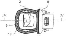
这些图中示出了一种真空吸尘器灰尘容器1的不同视图。真空吸尘器灰尘容器1包括一个基座本体2,该基座本体容纳了一个灰尘收集室3(参见图4)。The figures show different views of a vacuum
灰尘收集室3被适配成用于联接到一个真空吸尘器的一个旋流式灰尘分离单元21上(参见图7)。将灰尘收集室3联接到旋流式灰尘分离单元21上是使得该旋流式灰尘分离单元的一个灰尘出口开口4(参见图4)被流体性地连接到灰尘收集室3的一个灰尘进口开口5上。The
应注意的是,在这些图中示出的真空吸尘器灰尘容器1包括该旋流式灰尘分离单元21的一个区段,特别是末端区段。这个对应的末端区段在这些图(图3除外)中被示出并且用参考号6标示。应注意的是,将该旋流式灰尘分离单元21的一个区段6容纳在真空吸尘器灰尘容器1或基座本体2中不是强制性的。真空吸尘器灰尘容器1还可以被实现成不具有对应的旋流式灰尘分离单元21的任何部件。It should be noted that the vacuum
真空吸尘器灰尘容器1进一步包括一个把手7,该把手使得操纵和操作该真空吸尘器灰尘容器1很容易。具体地说,通过提供这样一个把手7可以极大地简化在清空该灰尘收集室3的过程中该真空吸尘器灰尘容器1的移除和再安装。The vacuum
真空吸尘器灰尘容器1进一步包括一个盖件8。盖件8被设置和适配成用于关闭灰尘收集室3的一个灰尘卸放开口9,这可以在图3和图4中最佳地看出。盖件8可以包括一个垫片或类似物,这样使得可以在盖件8与灰尘卸放开口9的下缘之间获得紧密的、特别是不漏流体和灰尘的密封。The vacuum
盖件8通过多个铰链接头11而被铰接地附接(即联接)到基座本体2上。这些铰链接头11被设置在基座本体2的一个底侧处、并且从该基座本体2的一个外部面上伸出。The
应注意的是,相对于真空吸尘器灰尘容器1的通常使用位置,盖件8和灰尘卸放开口9被定位在底部处,并且该旋流式灰尘分离单元的末端区段6和把手7被定位在顶部处。具体地说这意味着,该灰尘收集室3的灰尘进口开口5是设置成朝向顶侧或者在该顶侧处,并且灰尘卸放开口9和盖件8是设置在底侧处。It should be noted that, relative to the usual position of use of the vacuum
真空吸尘器灰尘容器1进一步包括一个致动机构12。如将在下文更详细地描述的,致动机构12被联接在盖件8与基座本体2之间、并且被适配和设计成用于控制盖件8的打开和/或关闭动作。The vacuum
致动机构12包括一个L形的(即,成角度的)杠杆13。杠杆13又包括一个第一腿14和一个第二腿15。第一腿14与第二腿15之间的角度大约是90度。The
第一腿14被铰接地连接到盖件8上,这样使得在盖件8与第一腿14之间的旋转动作是可能的。在盖件8与第一腿14之间的界面处的一条旋转轴线基本上平行于该铰链接头11的旋转轴线。应注意的是,不一定要将第一腿14固定地附接到盖件8上。然而,将该第一腿固定到盖件8上可以增强打开和关闭动作的可操作性。The
第二腿15是连接到基座本体2的一个外侧上。更详细的说,第二腿15是铰接地且可滑动地连接到基座本体2上。在此,在基座本体2的这个外侧处可以设置有多条滑轨16,第二腿15的远离第一腿14的一个末端区段被铰接地且可滑动地连接到这些滑轨上。可以在这些滑轨16的上端处设置多个末端止挡件17,从而限制第二腿15的打开动作并且因此限制盖件8的打开动作。The
在这些图中,盖件8和致动机构12被显示在盖件8的打开构形中。从这些图中可以容易地得出,该L形杠杆13在盖件8的关闭构形中将绕过真空吸尘器灰尘容器1或基座本体2的一个下缘18。应注意的是,下缘18对应于盖件8通过铰链接头11而被铰接地联接到基座本体2之处的这个边缘。In these figures, the
绕过该下缘18具体是指,第一腿14将基本上平行于并且沿着盖件8的一部分延伸。此外,第二腿15在这个关闭构形中将基本上平行于并且沿着基座本体2的外侧壁的一个对应区段延伸。应注意的是,盖件8和/或该侧壁可以包括多个凹陷,这些凹陷被适配成用于在这个关闭构形中将第一腿14和第二腿15至少部分地容纳在这些凹陷中。Around this
如从这些图中可以容易地看出,致动机构12提供了使用者主动控制盖件8的打开和关闭动作的可能性。这样具有的优点是可以在具有最小的或减小的灰尘打旋或弥散的情况下进行灰尘收集室3的灰尘卸放。此外,使用者可以有利地避免接触或触碰带灰尘的部分或面,这极大地增强了操作舒适性。As can be easily seen from these figures, the
关于图2、图4和图5,可以看到该致动机构12包括一个锁定单元19。该锁定单元19在本实例中被实施为一种钩。这个钩被设置和适配成用于将盖件8锁定在其完全打开的位置中。这个完全打开的位置对应于第二腿15抵靠这些末端止挡件17的情形。在替代方案中,或者此外,锁定单元19可以被设置和适配成用于将盖件8锁定在关闭位置中。总之,可以防止在清空该灰尘收集室3的过程中的无意地关闭盖件8以及在正常使用期间无意地打开该灰尘收集室3。With reference to FIGS. 2 , 4 and 5 , it can be seen that the
致动机构12、但特别地还有锁定单元19,可以被适配和设计成使得在盖件8的关闭位置中产生一个将盖件8推向关闭位置的压迫力。这样可以帮助避免在盖件8与灰尘卸放开口9的界面处的灰尘逃逸。The
现在参照图6和图7,这些图分别示出了真空吸尘器20的透视图和该真空吸尘器20的截面视图。真空吸尘器20包括一个旋流式灰尘分离单元21以及结合图1至图5描述的真空吸尘器灰尘容器1。Referring now to FIGS. 6 and 7 , these figures show a perspective view of the
旋流式灰尘分离单元21在本实例中是一个卧式旋流分离器,这意味着在正常操作期间,穿过该旋流分离器的主空气流被水平地、即平行于下面的地面被引导。The cyclonic
真空吸尘器灰尘容器1被安排和定位在真空吸尘器1的前侧处。具体地说,真空吸尘器灰尘容器1被可移除地附接到真空吸尘器20和旋流式灰尘分离单元21上而使得需要时可以容易地清空该灰尘收集室3。The vacuum
为了清空该灰尘收集室3,可以通过把手7将真空吸尘器灰尘容器1从真空吸尘器1上释放并移走。然后,可以使真空吸尘器灰尘容器1来到并进入用于卸放在灰尘收集室3中所装灰尘的适当状态和位置中。To empty the
对致动机构12(特别是杠杆13)和锁定单元19(若需要的话)进行操作将打开盖件8。使用者可以通过杠杆13来控制盖件8的打开,特别是打开速度和打开程度。因此,可以在不产生太多灰尘打旋的情况下以一种比较简单的方式从灰尘收集室3中卸放灰尘。除此之外,使用者可以在无需触碰带灰尘的表面和元件的情况下卸放灰尘。Operating the
Claims (10)
Translated fromChineseApplications Claiming Priority (3)
| Application Number | Priority Date | Filing Date | Title |
|---|---|---|---|
| PCT/EP2011/000844WO2012113414A1 (en) | 2011-02-22 | 2011-02-22 | Vacuum cleaner |
| EPPCT/EP2011/000844 | 2011-02-22 | ||
| PCT/EP2012/052994WO2012113821A1 (en) | 2011-02-22 | 2012-02-22 | Vacuum cleaner dust container and a vacuum cleaner |
Publications (2)
| Publication Number | Publication Date |
|---|---|
| CN103476312Atrue CN103476312A (en) | 2013-12-25 |
| CN103476312B CN103476312B (en) | 2016-08-10 |
Family
ID=44237322
Family Applications (4)
| Application Number | Title | Priority Date | Filing Date |
|---|---|---|---|
| CN201280008885.9AActiveCN103476312B (en) | 2011-02-22 | 2012-02-22 | Vacuum cleaner dust container and vacuum cleaner |
| CN2012800088420APendingCN103458753A (en) | 2011-02-22 | 2012-02-22 | Vacuum cleaner |
| CN2012800088492APendingCN103476311A (en) | 2011-02-22 | 2012-02-22 | Vacuum cleaner |
| CN201280008905.2AActiveCN103476313B (en) | 2011-02-22 | 2012-02-22 | vacuum cleaner |
Family Applications After (3)
| Application Number | Title | Priority Date | Filing Date |
|---|---|---|---|
| CN2012800088420APendingCN103458753A (en) | 2011-02-22 | 2012-02-22 | Vacuum cleaner |
| CN2012800088492APendingCN103476311A (en) | 2011-02-22 | 2012-02-22 | Vacuum cleaner |
| CN201280008905.2AActiveCN103476313B (en) | 2011-02-22 | 2012-02-22 | vacuum cleaner |
Country Status (7)
| Country | Link |
|---|---|
| US (4) | US20140020203A1 (en) |
| JP (4) | JP2014505565A (en) |
| KR (4) | KR20140004203A (en) |
| CN (4) | CN103476312B (en) |
| AU (4) | AU2012219632A1 (en) |
| CA (4) | CA2825686A1 (en) |
| WO (5) | WO2012113414A1 (en) |
Cited By (2)
| Publication number | Priority date | Publication date | Assignee | Title |
|---|---|---|---|---|
| CN109106283A (en)* | 2017-06-23 | 2019-01-01 | 戴森技术有限公司 | Foul separator and vacuum cleaner |
| CN113974486A (en)* | 2016-05-09 | 2022-01-28 | 伊莱克斯公司 | Connection plate for dust container of vacuum cleaner |
Families Citing this family (26)
| Publication number | Priority date | Publication date | Assignee | Title |
|---|---|---|---|---|
| US9649000B2 (en) | 2012-11-09 | 2017-05-16 | Aktiebolaget Electrolux | Cyclone dust separator arrangement, cyclone dust separator and cyclone vacuum cleaner |
| US9432215B2 (en) | 2013-05-21 | 2016-08-30 | Nicira, Inc. | Hierarchical network managers |
| WO2015123538A1 (en) | 2014-02-14 | 2015-08-20 | Techtronic Industries Co. Ltd. | Vacuum cleaner with a separator received within the dirt collection chamber |
| WO2016065146A1 (en) | 2014-10-22 | 2016-04-28 | Techtronic Industries Co. Ltd. | Vacuum cleaner having cyclonic separator |
| US9693665B2 (en) | 2014-10-22 | 2017-07-04 | Techtronic Industries Co. Ltd. | Vacuum cleaner having cyclonic separator |
| EP3209175B1 (en) | 2014-10-22 | 2023-01-04 | Techtronic Industries Co. Ltd. | Handheld vacuum cleaner |
| CN105747989B (en) | 2015-01-06 | 2020-06-26 | 创科实业有限公司 | Axial fan vacuum cleaner |
| US9885196B2 (en) | 2015-01-26 | 2018-02-06 | Hayward Industries, Inc. | Pool cleaner power coupling |
| US9909333B2 (en) | 2015-01-26 | 2018-03-06 | Hayward Industries, Inc. | Swimming pool cleaner with hydrocyclonic particle separator and/or six-roller drive system |
| GB2546543B (en) | 2016-01-22 | 2019-01-02 | Dyson Technology Ltd | Separating apparatus and vacuum cleaner |
| GB2546541B (en)* | 2016-01-22 | 2018-07-04 | Dyson Technology Ltd | Vacuum cleaning apparatus |
| GB2546542B (en) | 2016-01-22 | 2018-07-04 | Dyson Technology Ltd | Vacuum cleaner |
| EP3323335B1 (en) | 2016-11-17 | 2021-05-05 | Black & Decker Inc. | Cleaning device |
| US9896858B1 (en) | 2017-05-11 | 2018-02-20 | Hayward Industries, Inc. | Hydrocyclonic pool cleaner |
| US10156083B2 (en) | 2017-05-11 | 2018-12-18 | Hayward Industries, Inc. | Pool cleaner power coupling |
| US9885194B1 (en) | 2017-05-11 | 2018-02-06 | Hayward Industries, Inc. | Pool cleaner impeller subassembly |
| CN108113577A (en)* | 2017-12-19 | 2018-06-05 | 江苏美的清洁电器股份有限公司 | Dust catcher |
| CN110101345A (en)* | 2018-02-01 | 2019-08-09 | 燕成祥 | Dust-collecting box |
| CN110934532B (en)* | 2018-09-25 | 2021-09-17 | 添可智能科技有限公司 | Hand-held cleaning device |
| US11457783B2 (en)* | 2019-06-05 | 2022-10-04 | Lg Electronics Inc. | Cleaner |
| JP7157017B2 (en)* | 2019-07-26 | 2022-10-19 | 日立グローバルライフソリューションズ株式会社 | vacuum cleaner |
| DE112022003963T5 (en) | 2021-10-11 | 2024-07-04 | Milwaukee Electric Tool Corporation | BLOWER FOR A HANDHELD BLOWER |
| US12352274B2 (en) | 2022-03-21 | 2025-07-08 | Milwaukee Electric Tool Corporation | Axial blower |
| CN115153368B (en)* | 2022-06-13 | 2024-02-23 | 深圳市无限动力发展有限公司 | Dust collection base station |
| GB2621469A (en)* | 2022-06-29 | 2024-02-14 | Dyson Technology Ltd | Separation system for a vacuum cleaner |
| WO2025198144A1 (en)* | 2024-03-20 | 2025-09-25 | 삼성전자주식회사 | Robot cleaner, station and cleaning device |
Citations (5)
| Publication number | Priority date | Publication date | Assignee | Title |
|---|---|---|---|---|
| CN1951293A (en)* | 2005-10-17 | 2007-04-25 | 乐金电子(天津)电器有限公司 | Open/close device of dust collector |
| CN101511250A (en)* | 2006-09-01 | 2009-08-19 | 戴森技术有限公司 | A collection chamber for a vacuum cleaner |
| CN101653344A (en)* | 2008-08-20 | 2010-02-24 | 乐金电子(天津)电器有限公司 | Dust collecting barrel capable of automatically opening bottom cover |
| WO2010102399A1 (en)* | 2009-03-11 | 2010-09-16 | G.B.D. Corp. | Surface cleaning apparatus |
| JP4664741B2 (en)* | 2005-06-15 | 2011-04-06 | 株式会社東芝 | Vacuum cleaner and dust collector |
Family Cites Families (52)
| Publication number | Priority date | Publication date | Assignee | Title |
|---|---|---|---|---|
| US2121516A (en)* | 1937-10-18 | 1938-06-21 | Woo Jack | Condiment receptacle |
| US5090309A (en)* | 1991-04-09 | 1992-02-25 | Lai Fu Tung | Waste container |
| DK119093A (en)* | 1993-10-22 | 1995-04-23 | Joergen Sjoegreen | Universal Vacuum Cleaner |
| CN1179088A (en)* | 1995-01-27 | 1998-04-15 | 诺特特里有限公司 | Vaccuum cleaner |
| SE512295C2 (en)* | 1999-04-08 | 2000-02-28 | Electrolux Ab | Drainage system for a cyclone vacuum cleaner |
| US6168641B1 (en)* | 1998-06-26 | 2001-01-02 | Akteibolaget Electrolux | Cyclone separator device for a vacuum cleaner |
| GB2344745B (en)* | 1998-12-18 | 2002-06-05 | Notetry Ltd | Vacuum cleaner |
| FR2808988B1 (en)* | 2000-05-16 | 2002-07-19 | Seb Sa | WASTE COLLECTOR FOR VACUUM CLEANER |
| AU2001288590B2 (en)* | 2000-09-01 | 2006-09-21 | Royal Appliance Mfg. Co. | Bagless canister vacuum cleaner |
| SE518257C2 (en)* | 2001-01-11 | 2002-09-17 | Electrolux Ab | Device for a vacuum cleaner |
| FR2823091B1 (en)* | 2001-04-09 | 2003-06-13 | Seb Sa | DEVICE FOR COMPACTING WASTE IN A VACUUM |
| JP3699679B2 (en)* | 2001-12-28 | 2005-09-28 | 松下電器産業株式会社 | Vacuum cleaner |
| JP3749173B2 (en)* | 2001-12-28 | 2006-02-22 | 三洋電機株式会社 | Dust collector for vacuum cleaner and electric vacuum cleaner |
| ITMO20030012A1 (en)* | 2003-01-24 | 2004-07-25 | Soteco S P A | PERFECTED VACUUM CLEANER. |
| GB0307928D0 (en)* | 2003-04-05 | 2003-05-14 | Hoover Ltd | Vacuum cleaner |
| US7669282B2 (en)* | 2004-03-11 | 2010-03-02 | Lg Electronics Inc. | Vacuum cleaner |
| US20050198769A1 (en)* | 2004-03-11 | 2005-09-15 | Lg Electronics Inc. | Vacuum cleaner |
| KR100549990B1 (en)* | 2004-04-16 | 2006-02-08 | 삼성광주전자 주식회사 | Dust collector for vacuum cleaner |
| KR100606845B1 (en)* | 2004-10-08 | 2006-08-01 | 엘지전자 주식회사 | Multi Cyclone Dust Collector |
| KR100871484B1 (en) | 2004-12-14 | 2008-12-05 | 엘지전자 주식회사 | Dust collection unit for vacuum cleaner |
| KR100869000B1 (en)* | 2004-12-14 | 2008-11-17 | 엘지전자 주식회사 | Dust compression method of vacuum cleaner and dust compression device of vacuum cleaner |
| US7556662B2 (en) | 2005-01-31 | 2009-07-07 | Samsung Gwangju Electronics Co., Ltd. | Multi-cyclone dust separating apparatus |
| GB2426726B (en)* | 2005-05-27 | 2008-11-05 | Dyson Technology Ltd | Cyclonic separating apparatus |
| JP2007020769A (en)* | 2005-07-14 | 2007-02-01 | Matsushita Electric Ind Co Ltd | Electric vacuum cleaner |
| KR100630952B1 (en) | 2005-10-11 | 2006-10-04 | 삼성광주전자 주식회사 | Multi cyclone dust collector for vacuum cleaner and vacuum cleaner having same |
| KR100688613B1 (en)* | 2005-10-11 | 2007-03-02 | 삼성광주전자 주식회사 | Multi Cyclone Dust Collector for Vacuum Cleaner |
| JP2007125294A (en)* | 2005-11-07 | 2007-05-24 | Sharp Corp | Dust collector and vacuum cleaner provided with the same |
| US8544143B2 (en)* | 2005-12-10 | 2013-10-01 | Lg Electronics Inc. | Vacuum cleaner with removable dust collector, and methods of operating the same |
| US7882592B2 (en)* | 2005-12-10 | 2011-02-08 | Lg Electronics Inc. | Vacuum cleaner |
| EP1857032B1 (en)* | 2006-05-17 | 2012-05-16 | LG Electronics Inc. | Vacuum cleaner having primary and secondary cyclone units |
| GB2442211A (en)* | 2006-09-29 | 2008-04-02 | Vax Ltd | Cyclonic separator with dual dust receptacle arrangement |
| CN100486508C (en)* | 2006-10-20 | 2009-05-13 | 泰怡凯电器(苏州)有限公司 | Multi-stage spiral-flow-wind dust sucking device |
| JP2010508883A (en)* | 2006-11-03 | 2010-03-25 | デウ エレクトロニクス コーポレーション | Vacuum cleaner |
| KR100776404B1 (en)* | 2007-02-05 | 2007-11-16 | 삼성광주전자 주식회사 | Dust collector of vacuum cleaner |
| EP2090211B1 (en)* | 2007-03-08 | 2013-09-11 | Kingclean Electric Co., Ltd. | A dust separating device of a cleaner |
| US20080264015A1 (en)* | 2007-04-30 | 2008-10-30 | Samsung Gwangju Electronics Co., Ltd | Dust compressing apparatus of vacuum cleaner |
| US7611558B2 (en)* | 2007-04-30 | 2009-11-03 | Samsung Gwangju Electronics Co., Ltd. | Dust compressing apparatus of vacuum cleaner |
| US7785381B2 (en)* | 2007-04-30 | 2010-08-31 | Samsung Gwangju Electronics Co., Ltd. | Dust collecting apparatus with combined compacting and filter cleaning for a vacuum cleaner |
| US20080263815A1 (en)* | 2007-04-30 | 2008-10-30 | Samsung Gwangju Electronics Co., Ltd. | Dust collecting apparatus for vacuum cleaner |
| GB2488479B (en)* | 2007-05-24 | 2012-10-10 | Techtronic Floor Care Tech Ltd | Dual stage cyclonic vacuum cleaner |
| RU2428916C2 (en) | 2007-07-16 | 2011-09-20 | ЭлДжи ЭЛЕКТРОНИКС ИНК. | Vacuum cleaner |
| US8191203B2 (en)* | 2008-01-16 | 2012-06-05 | Samsung Electronics Co., Ltd. | Dust receptacle and vacuum cleaner having the same |
| CN201179039Y (en)* | 2008-02-04 | 2009-01-14 | 汪伟 | Vortex separation apparatus of horizontal vacuum cleaner |
| US8152913B2 (en)* | 2009-02-16 | 2012-04-10 | Samsung Gwangju Electronics Co., Ltd. | Dust collecting apparatus for compressing dust |
| US8713752B2 (en)* | 2009-03-13 | 2014-05-06 | Lg Electronics Inc. | Vacuum cleaner |
| US20100236013A1 (en)* | 2009-03-17 | 2010-09-23 | Electrolux Home Care Products, Inc. | Vacuum Cleaner Sensor |
| US20110056045A1 (en)* | 2009-09-10 | 2011-03-10 | Electrolux Home Care Products, Inc. | Dirt Cup Latch Mechanism |
| AU2010317746B2 (en) | 2009-11-16 | 2013-08-29 | Dyson Technology Limited | A surface treating appliance |
| JP5577853B2 (en)* | 2010-05-31 | 2014-08-27 | 三菱電機株式会社 | Electric vacuum cleaner |
| CA2744740C (en)* | 2010-06-29 | 2015-08-04 | Emerson Electric Co. | Accessory wand storage assembly for use with vacuum appliances, and vacuums using the same |
| JP2012200385A (en)* | 2011-03-25 | 2012-10-22 | Panasonic Corp | Electric vacuum cleaner |
| EP2564750B1 (en)* | 2011-09-02 | 2018-11-21 | Samsung Electronics Co., Ltd. | Vacuum cleaner having a dust separating apparatus |
- 2011
- 2011-02-22WOPCT/EP2011/000844patent/WO2012113414A1/enactiveApplication Filing
- 2012
- 2012-02-22KRKR1020137023935Apatent/KR20140004203A/ennot_activeWithdrawn
- 2012-02-22KRKR1020137023893Apatent/KR20140017576A/ennot_activeWithdrawn
- 2012-02-22AUAU2012219632Apatent/AU2012219632A1/ennot_activeAbandoned
- 2012-02-22CACA2825686Apatent/CA2825686A1/ennot_activeAbandoned
- 2012-02-22CNCN201280008885.9Apatent/CN103476312B/enactiveActive
- 2012-02-22USUS14/000,372patent/US20140020203A1/ennot_activeAbandoned
- 2012-02-22WOPCT/EP2012/053027patent/WO2012113840A1/enactiveApplication Filing
- 2012-02-22CNCN2012800088420Apatent/CN103458753A/enactivePending
- 2012-02-22JPJP2013553971Apatent/JP2014505565A/enactivePending
- 2012-02-22AUAU2012219519Apatent/AU2012219519A1/ennot_activeAbandoned
- 2012-02-22CACA2825601Apatent/CA2825601A1/ennot_activeAbandoned
- 2012-02-22AUAU2012219643Apatent/AU2012219643A1/ennot_activeAbandoned
- 2012-02-22KRKR1020137023890Apatent/KR20140009338A/ennot_activeWithdrawn
- 2012-02-22WOPCT/EP2012/053025patent/WO2012113839A1/enactiveApplication Filing
- 2012-02-22KRKR1020137023932Apatent/KR20140009340A/ennot_activeWithdrawn
- 2012-02-22JPJP2013554883Apatent/JP2014506516A/enactivePending
- 2012-02-22AUAU2012219521Apatent/AU2012219521A1/ennot_activeAbandoned
- 2012-02-22CNCN2012800088492Apatent/CN103476311A/enactivePending
- 2012-02-22CACA2825685Apatent/CA2825685A1/ennot_activeAbandoned
- 2012-02-22USUS14/000,360patent/US20140020204A1/ennot_activeAbandoned
- 2012-02-22WOPCT/EP2012/052994patent/WO2012113821A1/enactiveApplication Filing
- 2012-02-22JPJP2013554880Apatent/JP2014506515A/enactivePending
- 2012-02-22USUS14/000,381patent/US20140053366A1/ennot_activeAbandoned
- 2012-02-22CNCN201280008905.2Apatent/CN103476313B/enactiveActive
- 2012-02-22JPJP2013554884Apatent/JP2014506517A/enactivePending
- 2012-02-22CACA2825035Apatent/CA2825035A1/ennot_activeAbandoned
- 2012-02-22WOPCT/EP2012/052980patent/WO2012113814A1/enactiveApplication Filing
- 2012-02-22USUS14/000,368patent/US20140026356A1/ennot_activeAbandoned
Patent Citations (5)
| Publication number | Priority date | Publication date | Assignee | Title |
|---|---|---|---|---|
| JP4664741B2 (en)* | 2005-06-15 | 2011-04-06 | 株式会社東芝 | Vacuum cleaner and dust collector |
| CN1951293A (en)* | 2005-10-17 | 2007-04-25 | 乐金电子(天津)电器有限公司 | Open/close device of dust collector |
| CN101511250A (en)* | 2006-09-01 | 2009-08-19 | 戴森技术有限公司 | A collection chamber for a vacuum cleaner |
| CN101653344A (en)* | 2008-08-20 | 2010-02-24 | 乐金电子(天津)电器有限公司 | Dust collecting barrel capable of automatically opening bottom cover |
| WO2010102399A1 (en)* | 2009-03-11 | 2010-09-16 | G.B.D. Corp. | Surface cleaning apparatus |
Cited By (3)
| Publication number | Priority date | Publication date | Assignee | Title |
|---|---|---|---|---|
| CN113974486A (en)* | 2016-05-09 | 2022-01-28 | 伊莱克斯公司 | Connection plate for dust container of vacuum cleaner |
| CN109106283A (en)* | 2017-06-23 | 2019-01-01 | 戴森技术有限公司 | Foul separator and vacuum cleaner |
| CN109106283B (en)* | 2017-06-23 | 2021-08-24 | 戴森技术有限公司 | Dirt Separators and Vacuum Cleaners |
Also Published As
| Publication number | Publication date |
|---|---|
| JP2014506516A (en) | 2014-03-17 |
| CN103476311A (en) | 2013-12-25 |
| US20140020204A1 (en) | 2014-01-23 |
| AU2012219521A1 (en) | 2013-08-01 |
| CA2825035A1 (en) | 2012-08-30 |
| US20140020203A1 (en) | 2014-01-23 |
| CN103476313A (en) | 2013-12-25 |
| CA2825601A1 (en) | 2012-08-30 |
| WO2012113839A1 (en) | 2012-08-30 |
| KR20140009340A (en) | 2014-01-22 |
| JP2014505565A (en) | 2014-03-06 |
| CN103458753A (en) | 2013-12-18 |
| CA2825686A1 (en) | 2012-08-30 |
| CN103476313B (en) | 2015-11-25 |
| CA2825685A1 (en) | 2012-08-30 |
| KR20140004203A (en) | 2014-01-10 |
| JP2014506517A (en) | 2014-03-17 |
| WO2012113821A1 (en) | 2012-08-30 |
| KR20140009338A (en) | 2014-01-22 |
| WO2012113414A1 (en) | 2012-08-30 |
| WO2012113814A1 (en) | 2012-08-30 |
| AU2012219632A1 (en) | 2013-08-01 |
| US20140053366A1 (en) | 2014-02-27 |
| US20140026356A1 (en) | 2014-01-30 |
| AU2012219643A1 (en) | 2013-08-01 |
| AU2012219519A1 (en) | 2013-08-01 |
| WO2012113840A1 (en) | 2012-08-30 |
| KR20140017576A (en) | 2014-02-11 |
| JP2014506515A (en) | 2014-03-17 |
| CN103476312B (en) | 2016-08-10 |
Similar Documents
| Publication | Publication Date | Title |
|---|---|---|
| CN103476312B (en) | Vacuum cleaner dust container and vacuum cleaner | |
| US10893785B2 (en) | Cleaning appliance | |
| US20220400920A1 (en) | Dirt separation device | |
| CN103860103B (en) | Cleaning appliance | |
| CN103829879B (en) | Cleaning appliance | |
| US20190200830A1 (en) | Cleaning appliance | |
| KR20090079143A (en) | Dust bin and vacuum cleaner with same | |
| KR20230165182A (en) | Cleaner | |
| EP2677912B1 (en) | Vacuum cleaner dust container and a vacuum cleaner | |
| EP2677914A1 (en) | Vacuum cleaner |
Legal Events
| Date | Code | Title | Description |
|---|---|---|---|
| C06 | Publication | ||
| PB01 | Publication | ||
| SE01 | Entry into force of request for substantive examination | ||
| SE01 | Entry into force of request for substantive examination | ||
| C14 | Grant of patent or utility model | ||
| GR01 | Patent grant |