CN103472885A - Maximum power-point tracking method applied to multistage-type grid-connected photovoltaic electricity-generating system - Google Patents
Maximum power-point tracking method applied to multistage-type grid-connected photovoltaic electricity-generating systemDownload PDFInfo
- Publication number
- CN103472885A CN103472885ACN2013103623048ACN201310362304ACN103472885ACN 103472885 ACN103472885 ACN 103472885ACN 2013103623048 ACN2013103623048 ACN 2013103623048ACN 201310362304 ACN201310362304 ACN 201310362304ACN 103472885 ACN103472885 ACN 103472885A
- Authority
- CN
- China
- Prior art keywords
- voltage
- grid
- photovoltaic
- array
- maximum power
- Prior art date
- Legal status (The legal status is an assumption and is not a legal conclusion. Google has not performed a legal analysis and makes no representation as to the accuracy of the status listed.)
- Granted
Links
- 238000000034methodMethods0.000titleclaimsabstractdescription34
- 238000010248power generationMethods0.000claimsabstractdescription40
- 238000005070samplingMethods0.000claimsabstractdescription6
- 239000003990capacitorSubstances0.000claimsdescription14
- 230000006641stabilisationEffects0.000claimsdescription12
- 238000011105stabilizationMethods0.000claimsdescription12
- 230000007423decreaseEffects0.000claimsdescription7
- 230000008859changeEffects0.000claimsdescription5
- 238000013178mathematical modelMethods0.000claimsdescription3
- 230000008569processEffects0.000claimsdescription3
- 238000004451qualitative analysisMethods0.000claimsdescription3
- 230000009466transformationEffects0.000claimsdescription3
- 238000013139quantizationMethods0.000abstractdescription2
- 210000004027cellAnatomy0.000description12
- 238000010586diagramMethods0.000description11
- 230000033228biological regulationEffects0.000description3
- 230000008901benefitEffects0.000description2
- 230000004044responseEffects0.000description2
- 230000000630rising effectEffects0.000description2
- 238000004458analytical methodMethods0.000description1
- 230000009286beneficial effectEffects0.000description1
- 230000003139buffering effectEffects0.000description1
- 210000003850cellular structureAnatomy0.000description1
- 238000006243chemical reactionMethods0.000description1
- 238000011217control strategyMethods0.000description1
- 230000008878couplingEffects0.000description1
- 238000010168coupling processMethods0.000description1
- 238000005859coupling reactionMethods0.000description1
- 238000012938design processMethods0.000description1
- 230000000694effectsEffects0.000description1
- 230000008030eliminationEffects0.000description1
- 238000003379elimination reactionMethods0.000description1
- 238000004146energy storageMethods0.000description1
- 238000001914filtrationMethods0.000description1
- 230000003068static effectEffects0.000description1
Images


Classifications
- Y—GENERAL TAGGING OF NEW TECHNOLOGICAL DEVELOPMENTS; GENERAL TAGGING OF CROSS-SECTIONAL TECHNOLOGIES SPANNING OVER SEVERAL SECTIONS OF THE IPC; TECHNICAL SUBJECTS COVERED BY FORMER USPC CROSS-REFERENCE ART COLLECTIONS [XRACs] AND DIGESTS
- Y02—TECHNOLOGIES OR APPLICATIONS FOR MITIGATION OR ADAPTATION AGAINST CLIMATE CHANGE
- Y02E—REDUCTION OF GREENHOUSE GAS [GHG] EMISSIONS, RELATED TO ENERGY GENERATION, TRANSMISSION OR DISTRIBUTION
- Y02E10/00—Energy generation through renewable energy sources
- Y02E10/50—Photovoltaic [PV] energy
- Y02E10/56—Power conversion systems, e.g. maximum power point trackers
Landscapes
- Control Of Electrical Variables (AREA)
Abstract
Translated fromChinese
Description
Translated fromChinese技术领域technical field
本发明属于太阳能分布式可再生新能源发电技术领域,具体涉及一种应用于多级式光伏并网发电系统的最大功率点追踪方法。The invention belongs to the technical field of solar distributed renewable new energy power generation, and specifically relates to a maximum power point tracking method applied to a multi-stage photovoltaic grid-connected power generation system.
背景技术Background technique
光伏电池的输出功率特性具有很强的非线性,其最大输出功率及最大输出功率点电压与电流随着温度、光照强度、光照的不均衡度等因素变化。采用有效的最大功率点跟踪算法,才能提高光伏发电系统对光伏电池组件电能的利用率。目前,光伏发电系统实现最大功率点跟踪的方法有很多:定电压法、扰动观察法、增量电导法、智能MPPT以及很多的新型算法等等,但是这些方法各有其优缺点及适用范围,定电压法是一种开环MPPT算法,控制简单快速,但由于忽略了温度对光伏电池板输出电压的影响,因此,温差越大,定电压发的跟踪误差越大;扰动观察法具有控制概念清晰、简单、被测参数少等优点,但是电压初始值及扰动电压步长对跟踪精度与速度有较大影响;增量电导法的主要优点是控制稳定度高,当外部环境参数变化时,系统能平稳的追踪其变化,且与光伏电池的特性与参数无关,但是其对控制系统的要求较高,另外,电压初始值对系统启动过程中的跟踪性能有较大影响;智能MPPT设计过程比较复杂,不易于编程。The output power characteristics of photovoltaic cells are highly nonlinear. The maximum output power and the voltage and current at the maximum output power point vary with factors such as temperature, light intensity, and light imbalance. Only by adopting an effective maximum power point tracking algorithm can the photovoltaic power generation system improve the utilization rate of photovoltaic cell module electric energy. At present, there are many methods for realizing maximum power point tracking in photovoltaic power generation systems: constant voltage method, disturbance observation method, incremental conductance method, intelligent MPPT and many new algorithms, etc., but each of these methods has its own advantages and disadvantages and scope of application. The constant voltage method is an open-loop MPPT algorithm, which is simple and fast to control, but because the influence of temperature on the output voltage of photovoltaic panels is ignored, the greater the temperature difference, the greater the tracking error of the constant voltage generation; the disturbance and observation method has a control concept Clear, simple, few parameters to be measured, etc., but the initial value of the voltage and the step size of the disturbance voltage have a great influence on the tracking accuracy and speed; the main advantage of the incremental conductance method is the high control stability. When the external environment parameters change, The system can track its changes smoothly and has nothing to do with the characteristics and parameters of photovoltaic cells, but it has high requirements for the control system. In addition, the initial value of the voltage has a great impact on the tracking performance during the system startup process; the intelligent MPPT design process More complicated and not easy to program.
发明内容Contents of the invention
本发明的目的是提供一种应用于多级式光伏并网发电系统的最大功率点跟踪方法,稳态条件下能够快速准确地实现最大功率点跟踪,仅需对阵列输出电压进行采样与观测,且能有效避免母线电压崩溃现象,而且该方法不受光照强弱的影响,可以实现全功率段的有效稳态跟踪。The purpose of the present invention is to provide a maximum power point tracking method applied to a multi-stage photovoltaic grid-connected power generation system, which can quickly and accurately realize maximum power point tracking under steady-state conditions, and only needs to sample and observe the output voltage of the array. And it can effectively avoid bus voltage collapse, and the method is not affected by the intensity of light, and can realize effective steady-state tracking in the full power range.
本发明所采用的技术方案是,应用于多级式光伏并网发电系统的最大功率点跟踪方法,具体按照以下步骤实施:The technical solution adopted in the present invention is to apply to the maximum power point tracking method of the multi-stage photovoltaic grid-connected power generation system, and specifically implement according to the following steps:
步骤1:对光伏阵列电压、直流母线电压、并网电流和电网电压进行采样;Step 1: Sampling the photovoltaic array voltage, DC bus voltage, grid-connected current and grid voltage;
步骤2:对多级式光伏并网发电系统进行建模,并分析得出系统的稳定性工作条件;Step 2: Model the multi-stage photovoltaic grid-connected power generation system, and analyze the stable working conditions of the system;
步骤3:对多级式光伏并网发电系统进行最大功率点跟踪。Step 3: Carry out maximum power point tracking for the multi-stage photovoltaic grid-connected power generation system.
本发明的特点还在于,The present invention is also characterized in that,
其中的步骤2对多级式光伏并网发电系统进行建模,并分析得出系统的稳定性工作条件,具体按照以下步骤实施:In Step 2, the multi-stage photovoltaic grid-connected power generation system is modeled, and the stable working conditions of the system are obtained through analysis. The specific implementation is as follows:
用可控直流电压源代表直流母线,控制其电压为母线电压给定Vdcref,将DC_DC变换器等效为理想的直流变压器,变压器变比满足
其中,T为并网周期,Dvdc为一个并网周期内母线电压的变化量,而母线电压经过控制以后波动非常小,可以忽略,得出:Among them, T is the grid-connected period, Dvdc is the variation of the bus voltage in a grid-connected period, and the fluctuation of the bus voltage after control is very small, which can be ignored, and it can be concluded that:
Pref=P2=P1,Pref =P2 =P1 ,
结合光伏电池组件的工程数学模型Iz=f(Iph,V)=Iph-ε[exp(ξVz)-1]与上式可以得到如下式表示的光伏并网发电系统动态模型,式中,Combining the engineering mathematical model Iz =f(Iph ,V)=Iph -ε[exp(ξVz )-1] of photovoltaic cell modules with the above formula, the dynamic model of photovoltaic grid-connected power generation system can be obtained as follows, the formula middle,
其中,Iz为光伏组件输出电流,Iph为电池组件的等效光生电流,Vz为光伏组件输出电压,ε=npI0,np为并联电池单元数目,I0为光伏电池内部等效二极管的P-N结反向饱和电流,ξ=q/nckcTns,q为电子电荷量,nc为二极管特性因子,kc为波尔兹曼常数,T为光伏电池绝对温度,ns为串联电池单元数目;Among them, Iz is the output current of the photovoltaic module, Iph is the equivalent photogenerated current of the battery module, Vz is the output voltage of the photovoltaic module, ε=np I0 , np is the number of parallel battery cells, and I0 is the inside of the photovoltaic cell The reverse saturation current of the PN junction of the equivalent diode, ξ=q/nc kc Tns , q is the electron charge, nc is the diode characteristic factor, kc is the Boltzmann constant, T is the absolute temperature of the photovoltaic cell , ns is the number of battery cells connected in series;
对于单相系统,pref中含有交流成分,描述为:For a single-phase system, there is an AC component in pref , described as:
其中,
对于三相系统,pref中仅含有直流成分,用下式表示:For a three-phase system, only the DC component is contained in pref , expressed by the following formula:
直流滤波电容中储存一定的能量,且存在:A certain amount of energy is stored in the DC filter capacitor, and there are:
ppv=pref+icvpv,ppv =pref +ic vpv ,
由以上对多级式光伏并网发电系统的建模,定性分析得出稳定性规律:在光伏阵列P-V曲线最大功率点左侧,如果对给定功率pref一个正扰动,则光伏阵列电压VPV下降,光伏阵列输出功率ppv下降,如果连续施加正扰动,则阵列电压会持续向左移动导致系统崩溃;如果对给定功率pref一个负扰动,则光伏阵列的电压VPV上升,光伏阵列输出功率ppv上升,如果持续施加负扰动,则阵列电压会持续向右移动直到进入最大功率点右侧区域;在最大功率点右侧,对给定功率pref一个正扰动,则光伏阵列电压VPV下降,光伏阵列输出功率ppv上升,连续施加正扰动会使阵列电压持续向左运动,输出功率不断上升,直至越过最大功率点进入左侧区域;所以对于多级式光伏并网发电系统,不管是三相还是单相,光伏阵列的稳定工作点都在包括最大功率点在内的右侧区域,最大功率点左侧区域为非稳定工作区;在非稳定区域时通过减小并网逆变器输出功率改变光伏阵列输出电压的运动轨迹,从而使其进入稳定工作区。Based on the above modeling of the multi-stage photovoltaic grid-connected power generation system, the qualitative analysis shows the stability law: on the left side of the maximum power point of the photovoltaic array PV curve, if there is a positive disturbance to the given power pref , the photovoltaic array voltage VPV drops, the output power ppv of the photovoltaic array decreases, if a positive disturbance is continuously applied, the array voltage will continue to move to the left and cause the system to collapse; if a negative disturbance is given to the given power pref , the voltage VPV of the photovoltaic array rises, and the The array output power ppv rises, if a negative disturbance is continuously applied, the array voltage will continue to move to the right until it enters the area on the right side of the maximum power point; on the right side of the maximum power point, a positive disturbance for a given power pref , the photovoltaic array As the voltage VPV drops, the output power ppv of the photovoltaic array rises. Continuously applying positive disturbances will cause the array voltage to move continuously to the left, and the output power will continue to rise until it crosses the maximum power point and enters the left area; so for multi-stage photovoltaic grid-connected power generation System, whether it is three-phase or single-phase, the stable operating point of the photovoltaic array is in the right area including the maximum power point, and the left area of the maximum power point is the unstable operating area; in the unstable area, by reducing and The output power of the grid inverter changes the trajectory of the output voltage of the photovoltaic array, so that it enters a stable working area.
其中的步骤3对多级式光伏并网发电系统进行最大功率点跟踪,具体按照以下步骤实施:In step 3, the maximum power point tracking of the multi-level photovoltaic grid-connected power generation system is carried out according to the following steps:
利用DC_DC变换器实现母线稳压控制,选用Boost电路,采用母线电压外环加电感电流内环控制,外环采用PI控制器,内环采用P控制器,利用并网逆变器实现最大功率点跟踪,在光伏阵列电压稳定工作时以一定步长给并网功率值施加一个正扰动信号,若光伏阵列电压下降速率逐渐减小并再次趋于稳定,则证明光伏阵列输出电压位于最大输出功率点电压右侧,此时继续给并网功率施加正扰动;若阵列电压下降速率逐渐增大,电压值无法稳定,则证明光伏阵列工作点在最大功率点左侧,此时对并网功率施加负扰动,使光伏阵列工作电压恢复至最大功率点电压右侧,稳定后继续以一定步长给并网功率施加正扰动使光伏阵列工作电压点趋于最大功率点电压;在光伏阵列输出电压变化过程中,不对并网功率进行改变。Use DC_DC converter to realize busbar voltage stabilization control, select Boost circuit, adopt busbar voltage outer loop plus inductance current inner loop control, outer loop adopt PI controller, inner loop adopt P controller, use grid-connected inverter to realize maximum power point Tracking, when the voltage of the photovoltaic array is stable, a positive disturbance signal is applied to the grid-connected power value with a certain step size. If the voltage drop rate of the photovoltaic array gradually decreases and becomes stable again, it proves that the output voltage of the photovoltaic array is at the maximum output power point On the right side of the voltage, continue to apply positive disturbances to the grid-connected power at this time; if the drop rate of the array voltage gradually increases and the voltage value cannot be stabilized, it proves that the operating point of the photovoltaic array is on the left side of the maximum power point, and a negative disturbance is applied to the grid-connected power at this time. disturbance, so that the working voltage of the photovoltaic array returns to the right side of the maximum power point voltage, and after stabilization, continue to apply a positive disturbance to the grid-connected power with a certain step size so that the working voltage point of the photovoltaic array tends to the maximum power point voltage; during the change process of the output voltage of the photovoltaic array In , the grid-connected power is not changed.
本发明的有益效果是,该方法虽然不具有动态跟踪性能,但其稳态条件下能够快速准确地实现最大功率点跟踪,仅需对阵列输出电压进行采样与观测,其实现成本低,算法简单可靠,且能有效避免母线电压崩溃现象;而且该算法不受光照强弱的影响,可以实现全功率段的有效稳态跟踪,所以该方法适用于光照较弱以及光照相对较稳定的场合;另外该算法不会受到采样量化误差的影响,且控制量精度越高,给定步进功率增量越小,越能准确跟踪光伏阵列的最大输出功率点,还可根据系统输出功率值采用变步长法实现稳态条件下的快速跟踪。The beneficial effect of the present invention is that although the method does not have dynamic tracking performance, it can quickly and accurately realize maximum power point tracking under steady-state conditions, and only needs to sample and observe the output voltage of the array, and its implementation cost is low and the algorithm is simple Reliable, and can effectively avoid bus voltage collapse; and the algorithm is not affected by the intensity of light, and can achieve effective steady-state tracking in the full power range, so this method is suitable for occasions where the light is weak and the light is relatively stable; in addition The algorithm will not be affected by sampling and quantization errors, and the higher the accuracy of the control quantity, the smaller the increment of the given step power, the more accurately it can track the maximum output power point of the photovoltaic array, and the variable step can also be used according to the system output power value The long method achieves fast tracking under steady-state conditions.
附图说明Description of drawings
图1是多级式光伏并网发电系统的示意图;Figure 1 is a schematic diagram of a multi-stage photovoltaic grid-connected power generation system;
图2是多级式光伏发电系统基于后级并网逆变器的MPPT控制框图,(a)为前级实现母线控制的框图,(b)为后级实现MPPT和并网电流控制的框图;Figure 2 is the MPPT control block diagram of the multi-stage photovoltaic power generation system based on the back-stage grid-connected inverter, (a) is the block diagram of the front-stage busbar control, (b) is the block diagram of the back-stage MPPT and grid-connected current control;
图3是多级式光伏发电系统基于前级DC_DC变换器的MPPT控制框图,(a)为前级实现MPPT控制的框图,(b)为后级实现母线稳压控制和并网电流控制的框图;Figure 3 is the MPPT control block diagram of the multi-stage photovoltaic power generation system based on the front-stage DC_DC converter, (a) is the block diagram of the front-stage MPPT control, (b) is the block diagram of the rear-stage bus voltage regulation control and grid-connected current control ;
图4是多级式光伏并网发电系统的等效模型;Figure 4 is an equivalent model of a multi-stage photovoltaic grid-connected power generation system;
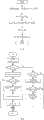
图5是基于功率扰动的最大功率点跟踪算法的流程图,其中(a)为母线稳压控制流程图,(b)为最大功率点跟踪算法流程图。Fig. 5 is a flow chart of the maximum power point tracking algorithm based on power disturbance, where (a) is the flow chart of the bus voltage regulation control, and (b) is the flow chart of the maximum power point tracking algorithm.
具体实施方式Detailed ways
下面结合附图和具体实施方式对本发明进行详细说明。The present invention will be described in detail below in conjunction with the accompanying drawings and specific embodiments.
多级式光伏并网发电系统一般由前级DC/DC变换器和后级DC/AC并网逆变器两部分组成,如图1,通常DC_DC变换器都具有升压功能,所以以BOOST为例说明。对于这种系统来说,一般有两种控制方法:基于后级并网逆变器的MPPT控制和基于前级DC/DC变换器的MPPT控制。图2、图3分别给出了这两种控制方法的控制框图,其中θ为锁相环输出的相角,ω为电网频率。基于后级并网逆变器的MPPT控制和利用前级Boost变换器实现直流母线的稳压控制,其中Boost变换器采用电压外环加电感电流内环控制,保证稳压控制可以取得较快的动态响应,因而可以获得较好的直流母线稳压性能,其稳压控制框图如图2(a)所示,其中H1(s)是控制信号到电感电流的传递函数,H2(s)是电感电流到直流母线电压的传递函数。后级逆变器实现MPPT功能和并网控制,通过对逆变器输出电流幅值的调节跟踪最大功率点,逆变器控制框图如图2(b)所示,其中H3(s)是并网逆变器控制模型。A multi-stage photovoltaic grid-connected power generation system is generally composed of two parts: the front-stage DC/DC converter and the rear-stage DC/AC grid-connected inverter, as shown in Figure 1. Usually, the DC_DC converter has a boost function, so BOOST is used as the Example. For this kind of system, there are generally two control methods: MPPT control based on the back-stage grid-connected inverter and MPPT control based on the front-stage DC/DC converter. Figure 2 and Figure 3 show the control block diagrams of these two control methods respectively, where θ is the phase angle of the phase-locked loop output, and ω is the grid frequency. Based on the MPPT control of the rear-stage grid-connected inverter and the use of the previous-stage Boost converter to realize the voltage stabilization control of the DC bus, the Boost converter adopts the voltage outer loop plus the inductor current inner loop control to ensure that the voltage stabilization control can achieve faster Dynamic response, so better DC bus voltage stabilization performance can be obtained, its voltage stabilization control block diagram is shown in Figure 2 (a), where H1 (s) is the transfer function from the control signal to the inductor current, H2 (s) is the transfer function of the inductor current to the DC bus voltage. The post-stage inverter realizes the MPPT function and grid-connected control, and tracks the maximum power point by adjusting the output current amplitude of the inverter. The inverter control block diagram is shown in Figure 2(b), where H3 (s) is Grid-connected inverter control model.
基于前级DC/DC变换器的MPPT控制如图3所示。图3(a)表示前级Boost变换器实现MPPT功能,图3(b)表示后级逆变器实现直流母线的稳压控制和并网电流控制,其中H4(s)是MPPT的指令信号到DC-DC变换器输出的传递函数,H3(s)是并网逆变器控制模型。由于光伏阵列的最大功率点跟踪是由Boost变换器完成,并且直流母线电容对输入逆变器的电压有缓冲作用,前级和后级电路之间基本不存在控制上的耦合问题,因此可以取得较好的控制性能。但是这种控制方案存在直流母线电压波动。本发明采用的是基于后级DC/AC并网逆变器的MPPT控制策略。The MPPT control based on the former stage DC/DC converter is shown in Fig. 3 . Figure 3(a) shows that the front-stage Boost converter implements the MPPT function, and Figure 3(b) shows that the rear-stage inverter realizes the DC bus voltage stabilization control and grid-connected current control, where H4 (s) is the command signal of MPPT The transfer function to the output of the DC-DC converter, H3 (s), is the grid-connected inverter control model. Since the maximum power point tracking of the photovoltaic array is completed by the Boost converter, and the DC bus capacitor has a buffering effect on the voltage input to the inverter, there is basically no control coupling problem between the front-stage and the rear-stage circuits, so it can be obtained Better control performance. But this control scheme has DC bus voltage fluctuations. The present invention adopts an MPPT control strategy based on a subsequent DC/AC grid-connected inverter.
本发明的具体实施步骤是:Concrete implementation steps of the present invention are:
步骤1:对光伏阵列电压、直流母线电压、并网电流和电网电压进行采样;Step 1: Sampling the photovoltaic array voltage, DC bus voltage, grid-connected current and grid voltage;
步骤2:对多级式光伏发电系统进行建模,并分析得出系统的稳定性工作条件,具体步骤如下:Step 2: Model the multi-level photovoltaic power generation system and analyze the stable working conditions of the system. The specific steps are as follows:
在多级式光伏并网发电系统中,前后级功率变换电路通过直流母线连接,直流母线电容起到滤波和储能的作用,在控制中必须对直流母线进行稳压控制,保证母线电压能够满足并网要求,所以直流母线相当于一个受控的直流电压源。而对于后级逆变部分而言,通过控制并网电流的幅值大小来调节光伏阵列的工作点,而电网电压通常是稳定的,所以并网电流与逆变器输出的功率是成正比的,所以可以将多级式光伏并网发电系统等效为图4所示的模型,其中可控直流电压源代表直流母线,控制其电压为母线电压给定Vdcref,而通常DC_DC变换器起到升压的作用,所以将其等效为理想的直流变压器,变压器变比满足
其中,T为并网周期,Dvdc为一个并网周期内母线电压的变化量,而母线电压经过控制以后波动非常小,可以忽略,所以可以得出Among them, T is the grid-connected period, Dvdc is the variation of the bus voltage within a grid-connected period, and the fluctuation of the bus voltage after control is very small and can be ignored, so it can be concluded that
Pref=P2=P1 (3)Pref =P2 =P1 (3)
结合光伏电池组件的工程数学模型(Iz=f(Iph,V)=Iph-ε[exp(ξVz)-1])与式(4)可以得到如式(5)表示的光伏发电系统动态模型。式中,Combining the engineering mathematical model of photovoltaic cell components (Iz =f(Iph ,V)=Iph -ε[exp(ξVz )-1]) and formula (4) can get the photovoltaic power generation as expressed in formula (5) System dynamic model. In the formula,
其中,Iz为光伏组件输出电流,Iph为电池组件的等效光生电流,Vz为光伏组件输出电压,ε=npI0(np为并联电池单元数目,I0为光伏电池内部等效二极管的P-N结反向饱和电流),ξ=q/nckcTns(q为电子电荷量,nc为二极管特性因子,kc为波尔兹曼常数,T为光伏电池绝对温度,ns为串联电池单元数目)。Among them, Iz is the output current of the photovoltaic module, Iph is the equivalent photogenerated current of the battery module, Vz is the output voltage of the photovoltaic module, ε=np I0 (np is the number of parallel battery cells, I0 is the inside of the photovoltaic cell PN junction reverse saturation current of the equivalent diode), ξ=q/nc kc Tns (q is the electron charge, nc is the diode characteristic factor, kc is the Boltzmann constant, T is the absolute value of the photovoltaic cell temperature, ns is the number of battery cells in series).
对于单相系统,pref中含有交流成分,理想情况下可以描述为:For a single-phase system, there is an AC component in pref which can ideally be described as:
其中,
对于三相系统,理想情况下pref中仅含有直流成分,用式(7)表示。For the three-phase system, ideally, only the DC component is contained in pref , which is represented by formula (7).
直流滤波电容中储存一定的能量,且存在:A certain amount of energy is stored in the DC filter capacitor, and there are:
ppv=pref+icvpv (8)ppv =pref +ic vpv (8)
由以上对多级式光伏发电并网系统的建模,可以定性分析得出稳定性规律:在光伏阵列P-V曲线最大功率点左侧,如果对给定功率pref一个正扰动,则光伏阵列电压VPV下降,光伏阵列输出功率ppv下降,如果连续施加正扰动,则阵列电压会持续向左移动导致系统崩溃;如果对给定功率pref一个负扰动,则光伏阵列的电压VPV上升,光伏阵列输出功率ppv上升,如果持续施加负扰动,则阵列电压会持续向右移动直到进入最大功率点右侧区域。在最大功率点右侧,对给定功率pref一个正扰动,则光伏阵列电压VPV下降,光伏阵列输出功率ppv上升,连续施加正扰动会使阵列电压持续向左运动,输出功率不断上升,直至越过最大功率点进入左侧区域。所以对于多级式光伏发电系统,不管是三相还是单相,光伏阵列的稳定工作点都在包括最大功率点在内的右侧区域,最大功率点左侧区域为非稳定工作区。在非稳定区域时可以通过减小并网逆变器输出功率改变光伏阵列输出电压的运动轨迹,从而使其进入稳定工作区。Based on the above modeling of the multi-stage photovoltaic power generation grid-connected system, the stability law can be obtained through qualitative analysis: on the left side of the maximum power point of the photovoltaic array PV curve, if there is a positive disturbance to the given power pref , the photovoltaic array voltage VPV drops, and the output power ppv of the photovoltaic array decreases. If a positive disturbance is continuously applied, the array voltage will continue to move to the left and cause the system to collapse; if a negative disturbance is applied to the given power pref , the voltage VPV of the photovoltaic array will rise, The output power ppv of the photovoltaic array rises. If the negative disturbance is continuously applied, the array voltage will continue to move to the right until it enters the area on the right side of the maximum power point. On the right side of the maximum power point, for a given power pref a positive disturbance, the photovoltaic array voltage VPV decreases, the photovoltaic array output power ppv increases, continuous positive disturbance will make the array voltage continue to move to the left, and the output power continues to rise , until it crosses the maximum power point and enters the left area. Therefore, for a multi-stage photovoltaic power generation system, whether it is three-phase or single-phase, the stable operating point of the photovoltaic array is in the right area including the maximum power point, and the left area of the maximum power point is the unstable operating area. In the unstable area, the output power of the grid-connected inverter can be reduced to change the trajectory of the output voltage of the photovoltaic array, so that it enters the stable working area.
步骤3:提出适用于多级式光伏并网发电系统的最大功率点跟踪方法,具体如下:Step 3: Propose a maximum power point tracking method suitable for multi-level photovoltaic grid-connected power generation systems, as follows:
利用DC_DC变换器实现母线稳压控制,以Boost控制为例,利用后级DC-AC逆变器实现最大功率点跟踪和并网控制,最大功率点跟踪的思路为:在光伏阵列电压稳定工作时以一定步长给并网功率值施加一个正扰动信号,若光伏阵列电压下降速率逐渐减小并再次趋于稳定,则证明光伏阵列输出电压位于最大输出功率点电压右侧,此时可继续给并网功率施加正扰动;若阵列电压下降速率逐渐增大,电压值无法稳定,则证明光伏阵列工作点在最大功率点左侧,此时应对并网功率施加负扰动,使光伏阵列工作电压恢复至最大功率点电压右侧,稳定后继续以一定步长给并网功率施加正扰动使光伏阵列工作电压点趋于最大功率点电压。在光伏阵列输出电压变化过程中,可不对并网功率进行改变。将该方法应用在多级式光伏发电系统中,在图2(b)控制框图中,MPPT控制器输入只需要VPV,IPV可省掉。Use the DC_DC converter to realize busbar voltage stabilization control. Taking Boost control as an example, use the post-stage DC-AC inverter to realize maximum power point tracking and grid-connected control. The idea of maximum power point tracking is: when the photovoltaic array voltage is stable Apply a positive disturbance signal to the grid-connected power value with a certain step size. If the voltage drop rate of the photovoltaic array gradually decreases and becomes stable again, it proves that the output voltage of the photovoltaic array is on the right side of the maximum output power point voltage. At this time, you can continue to give A positive disturbance is applied to the grid-connected power; if the drop rate of the array voltage gradually increases and the voltage value cannot be stabilized, it proves that the operating point of the photovoltaic array is on the left side of the maximum power point. At this time, a negative disturbance should be applied to the grid-connected power to restore the operating voltage of the photovoltaic array To the right side of the maximum power point voltage, after stabilization, continue to apply positive disturbance to the grid-connected power with a certain step size so that the operating voltage point of the photovoltaic array tends to the maximum power point voltage. During the change of the output voltage of the photovoltaic array, the grid-connected power may not be changed. Applying this method to a multi-level photovoltaic power generation system, in the control block diagram in Figure 2 (b), the MPPT controller input only needs VPV , and IPPV can be omitted.
图1是本发明基于的单相光伏并网发电系统,具体控制方法描述为:利用DC_DC变换器实现母线稳压控制,以Boost控制为例,采用母线Vdc电压外环加电感电流内环控制,外环采用PI控制器,比例积分(PI)调节兼顾了快速响应和消除静差两方面的要求,内环采用P控制器,以保证母线稳压的快速性。程序流程图如图5(a),给定直流母线电压Vdcref与实际的直流母线电压Vdc作差得到电压外环的误差信号Ev,电压误差信号Ev经过PI调节得到电感电流的给定值ILref,电流给定值ILref与实际电流IL作差得到电流内环的误差信号Ei,电流内环的误差信号Ei再进过P调节后作为发生PWM信号的比较值。其中,kvp、kvi是电压外环PI控制的比例系数和积分系数,kip是电感电流内环P控制的比例系数。Figure 1 is a single-phase photovoltaic grid-connected power generation system based on the present invention. The specific control method is described as follows: using a DC_DC converter to realize busbar voltage stabilization control, taking Boost control as an example, using busbar Vdc voltage outer loop plus inductor current inner loop control , the outer loop adopts PI controller, proportional-integral (PI) adjustment takes into account the requirements of fast response and elimination of static error, and the inner loop adopts P controller to ensure the rapidity of bus voltage regulation. The program flow chart is shown in Figure 5(a). The difference between the given DC bus voltage Vdcref and the actual DC bus voltage Vdc is used to obtain the error signal Ev of the voltage outer loop. The voltage error signal Ev is adjusted by PI to obtain the given value of the inductor current. The fixed value ILref , the difference between the current given value ILref and the actual current IL can be used to obtain the error signal Ei of the inner loop of the current, and the error signal Ei of the inner loop of the current can be used as a comparison value for generating the PWM signal after being adjusted by P. Among them, kvp and kvi are the proportional coefficient and integral coefficient of the voltage outer loop PI control, and kip is the proportional coefficient of the inductor current inner loop P control.
最大功率点跟踪采用功率扰动的方法,图5(b)是功率扰动法实现最大功率点跟踪的软件流程图。图5(b)中,以并网参考电流幅值信号Iref代替光伏阵列输出功率,首先对光伏阵列电压进行采样,采样结果存放在变量VPV中,进而计算当前给定电压信号VPVref与VPV的差值Errv。若VPV值连续多次与其前一次的值VPV_1相等(例如计数器counter1≥5),则认为光伏阵列输出电压稳定,此时可对功率值施加正扰动,将VPV的值赋予给定电压信号VPVref,然后根据前一次给定输出电流的扰动增量ΔI与Errv的比值大小确定新的给定并网电流幅值增量ΔI的大小,然后计算并网电流幅值给定Iref。当VPV值小于VPV_1值时,说明阵列电压正在下降,若阵列电压连续下降无法稳定时(例如计数器counter2≥10),则可以判断此时光伏阵列工作在非稳定工作区域,为了遏制光伏阵列电压下降趋势,是其尽可能快的回归到稳定工作区域,此时使并网电流幅值减去一个允许的最大负扰动增量,当光伏阵列输出电压稳定后,可再次对并网逆变器输出功率值施加正扰动,重复进行阵列电压的观测与处理。当VPV值大于VPV_1值时,说明在并网逆变器输出功率一定的情况下,阵列输出电压正在上升的过程中,此时阵列电压以稳定轨迹运行,其最终会收敛于稳定点,所以在阵列输出电压上升阶段不扰动并网输出功率,待其稳定工作后,再逐渐对并网逆变器输出功率施加扰动,最终实现最大功率点跟踪功能。Maximum power point tracking adopts the method of power perturbation, and Fig. 5(b) is a software flow chart of power perturbation method to realize maximum power point tracking. In Figure 5(b), the grid-connected reference current amplitude signal Iref is used to replace the output power of the photovoltaic array. First, the voltage of the photovoltaic array is sampled, and the sampling result is stored in the variable VPV , and then the current given voltage signal VPVref and VPV difference Errv . If the VPV value is equal to the previous value VPV_1 for several consecutive times (for example, the counter counter1≥5), it is considered that the output voltage of the photovoltaic array is stable. At this time, a positive disturbance can be applied to the power value to assign the value of VPV to a given voltage signal VPVref , and then determine the size of the new given grid-connected current amplitude increment ΔI according to the ratio of the disturbance increment ΔI of the previous given output current to Errv , and then calculate the given grid-connected current amplitude Iref . When the VPV value is less than the VPV_1 value, it means that the array voltage is falling. If the array voltage continues to drop and cannot be stabilized (for example, counter2≥10), it can be judged that the photovoltaic array is working in an unstable working area. In order to contain the photovoltaic array The voltage drop trend is to return to the stable working area as quickly as possible. At this time, the amplitude of the grid-connected current is reduced by a maximum allowable negative disturbance increment. When the output voltage of the photovoltaic array is stable, the grid-connected inverter can be performed again. A positive disturbance is applied to the output power value of the array, and the observation and processing of the array voltage are repeated. When the VPV value is greater than the VPV_1 value, it means that the array output voltage is rising under the condition that the output power of the grid-connected inverter is constant. At this time, the array voltage runs on a stable trajectory, and it will eventually converge to a stable point. Therefore, the grid-connected output power is not disturbed during the rising stage of the array output voltage. After it works stably, the output power of the grid-connected inverter is gradually disturbed, and finally the maximum power point tracking function is realized.
本发明虽然不具有动态跟踪性能,但其稳态条件下能够快速准确地实现最大功率点跟踪,仅需对阵列输出电压进行采样与观测,其实现成本低,算法简单可靠,且能有效避免母线电压崩溃现象,另外该算法不受光照强弱的影响,可以实现全功率段的有效稳态跟踪,所以该方法适用于光照较弱以及光照相对较稳定的场合。Although the present invention does not have dynamic tracking performance, it can quickly and accurately realize maximum power point tracking under steady-state conditions, and only needs to sample and observe the output voltage of the array. In addition, the algorithm is not affected by the intensity of light, and can achieve effective steady-state tracking in the full power range, so this method is suitable for occasions where the light is weak and the light is relatively stable.
Claims (3)
Translated fromChinese


Priority Applications (1)
| Application Number | Priority Date | Filing Date | Title |
|---|---|---|---|
| CN201310362304.8ACN103472885B (en) | 2013-08-19 | 2013-08-19 | Be applied to the maximum power point tracking method of multi-stag grid-connected photovoltaic system |
Applications Claiming Priority (1)
| Application Number | Priority Date | Filing Date | Title |
|---|---|---|---|
| CN201310362304.8ACN103472885B (en) | 2013-08-19 | 2013-08-19 | Be applied to the maximum power point tracking method of multi-stag grid-connected photovoltaic system |
Publications (2)
| Publication Number | Publication Date |
|---|---|
| CN103472885Atrue CN103472885A (en) | 2013-12-25 |
| CN103472885B CN103472885B (en) | 2015-09-30 |
Family
ID=49797774
Family Applications (1)
| Application Number | Title | Priority Date | Filing Date |
|---|---|---|---|
| CN201310362304.8AActiveCN103472885B (en) | 2013-08-19 | 2013-08-19 | Be applied to the maximum power point tracking method of multi-stag grid-connected photovoltaic system |
Country Status (1)
| Country | Link |
|---|---|
| CN (1) | CN103472885B (en) |
Cited By (12)
| Publication number | Priority date | Publication date | Assignee | Title |
|---|---|---|---|---|
| CN103795062A (en)* | 2014-02-27 | 2014-05-14 | 新疆希望电子有限公司 | Instruction voltage control method of photovoltaic micro-grid running inverter |
| CN104063264A (en)* | 2014-06-30 | 2014-09-24 | 国家电网公司 | Method of simulating multi-peak I-V curve of series photovoltaic module |
| CN104104112A (en)* | 2014-08-08 | 2014-10-15 | 深圳市创皓科技有限公司 | MPPT control method for photovoltaic grid-connected inverter of two-stage topology |
| CN104485728A (en)* | 2014-12-10 | 2015-04-01 | 新疆希望电子有限公司 | Control method for parallel connection droop of plurality of two-way energy storage current converters |
| CN105226963A (en)* | 2015-10-23 | 2016-01-06 | 艾思玛新能源技术(上海)有限公司苏州高新区分公司 | A kind of from net transformation device DC bus and maximum power control method and system |
| CN105652951A (en)* | 2016-03-16 | 2016-06-08 | 江苏大学 | Variable-step length MPPT control method |
| CN106300612A (en)* | 2016-08-26 | 2017-01-04 | 武汉理工大学 | The dual-mode control system of DC/DC and method in photovoltaic DC electric power system |
| CN112131812A (en)* | 2020-08-12 | 2020-12-25 | 北京华电天仁电力控制技术有限公司 | Multi-step-length parallel power real-time simulation system and method |
| CN112631364A (en)* | 2020-12-07 | 2021-04-09 | 马鞍山职业技术学院 | Self-adaptive photovoltaic global maximum power point tracking method |
| CN113809948A (en)* | 2021-08-10 | 2021-12-17 | 西安理工大学 | Feedback current compensation method for grid-connected inverter under condition of current divider sampling current |
| CN114070049A (en)* | 2021-10-26 | 2022-02-18 | 西安理工大学 | A kind of boost converter power switching control method |
| CN116931645A (en)* | 2023-07-14 | 2023-10-24 | 海信空调有限公司 | Photovoltaic air conditioner and power control method thereof |
Citations (3)
| Publication number | Priority date | Publication date | Assignee | Title |
|---|---|---|---|---|
| CN101119031A (en)* | 2007-06-08 | 2008-02-06 | 清华大学 | A fast and stable photovoltaic three-phase grid-connected control method for maximum power tracking |
| US20120268970A1 (en)* | 2011-04-20 | 2012-10-25 | Tae Won Lee | Electric generating system using solar cell |
| CN102809980A (en)* | 2012-07-31 | 2012-12-05 | 东南大学 | Maximum Power Tracking Method Based on Efficient Adaptive Perturbation-and-Observe Method |
- 2013
- 2013-08-19CNCN201310362304.8Apatent/CN103472885B/enactiveActive
Patent Citations (3)
| Publication number | Priority date | Publication date | Assignee | Title |
|---|---|---|---|---|
| CN101119031A (en)* | 2007-06-08 | 2008-02-06 | 清华大学 | A fast and stable photovoltaic three-phase grid-connected control method for maximum power tracking |
| US20120268970A1 (en)* | 2011-04-20 | 2012-10-25 | Tae Won Lee | Electric generating system using solar cell |
| CN102809980A (en)* | 2012-07-31 | 2012-12-05 | 东南大学 | Maximum Power Tracking Method Based on Efficient Adaptive Perturbation-and-Observe Method |
Cited By (17)
| Publication number | Priority date | Publication date | Assignee | Title |
|---|---|---|---|---|
| CN103795062B (en)* | 2014-02-27 | 2016-01-20 | 新疆希望电子有限公司 | The command voltage control method of photovoltaic microgrid operated inverter |
| CN103795062A (en)* | 2014-02-27 | 2014-05-14 | 新疆希望电子有限公司 | Instruction voltage control method of photovoltaic micro-grid running inverter |
| CN104063264A (en)* | 2014-06-30 | 2014-09-24 | 国家电网公司 | Method of simulating multi-peak I-V curve of series photovoltaic module |
| CN104104112A (en)* | 2014-08-08 | 2014-10-15 | 深圳市创皓科技有限公司 | MPPT control method for photovoltaic grid-connected inverter of two-stage topology |
| CN104485728A (en)* | 2014-12-10 | 2015-04-01 | 新疆希望电子有限公司 | Control method for parallel connection droop of plurality of two-way energy storage current converters |
| CN105226963B (en)* | 2015-10-23 | 2019-06-25 | 爱士惟新能源技术(扬中)有限公司 | A kind of off-network converter DC bus and maximum power control method and system |
| CN105226963A (en)* | 2015-10-23 | 2016-01-06 | 艾思玛新能源技术(上海)有限公司苏州高新区分公司 | A kind of from net transformation device DC bus and maximum power control method and system |
| CN105652951A (en)* | 2016-03-16 | 2016-06-08 | 江苏大学 | Variable-step length MPPT control method |
| CN106300612A (en)* | 2016-08-26 | 2017-01-04 | 武汉理工大学 | The dual-mode control system of DC/DC and method in photovoltaic DC electric power system |
| CN112131812A (en)* | 2020-08-12 | 2020-12-25 | 北京华电天仁电力控制技术有限公司 | Multi-step-length parallel power real-time simulation system and method |
| CN112131812B (en)* | 2020-08-12 | 2023-10-27 | 北京华电天仁电力控制技术有限公司 | Multi-step long parallel power real-time simulation system and method |
| CN112631364A (en)* | 2020-12-07 | 2021-04-09 | 马鞍山职业技术学院 | Self-adaptive photovoltaic global maximum power point tracking method |
| CN113809948A (en)* | 2021-08-10 | 2021-12-17 | 西安理工大学 | Feedback current compensation method for grid-connected inverter under condition of current divider sampling current |
| CN113809948B (en)* | 2021-08-10 | 2024-02-13 | 西安理工大学 | A feedback current compensation method for grid-connected inverters under shunt sampling current conditions |
| CN114070049A (en)* | 2021-10-26 | 2022-02-18 | 西安理工大学 | A kind of boost converter power switching control method |
| CN114070049B (en)* | 2021-10-26 | 2024-01-16 | 西安理工大学 | BOOST converter power switching control method |
| CN116931645A (en)* | 2023-07-14 | 2023-10-24 | 海信空调有限公司 | Photovoltaic air conditioner and power control method thereof |
Also Published As
| Publication number | Publication date |
|---|---|
| CN103472885B (en) | 2015-09-30 |
Similar Documents
| Publication | Publication Date | Title |
|---|---|---|
| CN103472885B (en) | Be applied to the maximum power point tracking method of multi-stag grid-connected photovoltaic system | |
| Kumar et al. | A comprehensive review on grid-tied solar photovoltaic system | |
| Fahad et al. | Particle swarm optimization based DC-link voltage control for two stage grid connected PV inverter | |
| Barra et al. | Predictive direct power control for photovoltaic grid connected system: An approach based on multilevel converters | |
| CN104810857B (en) | A single-phase photovoltaic grid-connected power generation system output power smoothing control device and control method | |
| CN106230257A (en) | A kind of two-way DC converter feedback linearization contragradience sliding-mode control | |
| Hou et al. | A flexible constant power generation scheme for photovoltaic system by error-based active disturbance rejection control and perturb & observe | |
| CN103455081B (en) | Based on the maximum power point tracing method that disturbance is observed | |
| Hu et al. | Maximum power point tracking control of a high power dc-dc converter for PV integration in MVDC distribution grids | |
| Omar et al. | Comparative study between PI and fuzzy-logic controllers for three-phase grid-connected photovoltaic systems | |
| Shoumi et al. | Design of the CUK converter with PI controller for battery charging | |
| Babu et al. | A novel adaptive fuzzy-based controller design using field programmable gate arrays for grid-connected photovoltaic systems | |
| Chakir et al. | Enhanced standalone photovoltaic system with novel multi-level inverter and nonlinear control for improved thd and converter efficiency | |
| Farook et al. | A comparative analysis to assess the power regulation in a grid-interfaced PV system using PI and fuzzy controllers | |
| Tsang et al. | PLL-less single stage grid-connected photovoltaic inverter with rapid maximum power point tracking | |
| Shah et al. | Grid interactive PV system with harmonic and reactive power compensation features using a novel fuzzy logic based MPPT | |
| CN107544610A (en) | A kind of photovoltaic MPPT control method based on MPP voltage regulations and gradient search | |
| CN114709811A (en) | A method for controlling IPOS cascade structure modules in a photovoltaic DC collection system | |
| Venkatesan et al. | Simulation and experimental validation of new MPPT algorithm with direct control method for PV application | |
| Sivapriyan et al. | Recent research trends in solar photovoltaic systems | |
| Rao et al. | Implementation of FPGA Based MPPT Techniques for Grid-Connected PV System. | |
| Hong et al. | A model-free control strategy for battery energy storage with an application to power accommodation | |
| CN105610186A (en) | Photovoltaic grid-connected control method having grid voltage supporting capability | |
| Khadake et al. | New control technique to improve the grid power by using PV-STATCOM | |
| Sivadasan et al. | A switched boost landsman converter with ANFIS based MPPT for grid connected wind energy system |
Legal Events
| Date | Code | Title | Description |
|---|---|---|---|
| C06 | Publication | ||
| PB01 | Publication | ||
| C10 | Entry into substantive examination | ||
| SE01 | Entry into force of request for substantive examination | ||
| C14 | Grant of patent or utility model | ||
| GR01 | Patent grant | ||
| CB03 | Change of inventor or designer information | ||
| CB03 | Change of inventor or designer information | Inventor after:Zhang Qi Inventor after:Sun Xiangdong Inventor after:Guo Lie Inventor after:An Shaoliang Inventor after:Ren Biying Inventor after:Yang Hui Inventor after:Li Chunyang Inventor after:Luo Yi Inventor after:Zhou Chengjun Inventor before:Zhang Qi Inventor before:Sun Xiangdong Inventor before:Guo Lie Inventor before:An Shaoliang Inventor before:Ren Biying Inventor before:Yang Hui | |
| TR01 | Transfer of patent right | ||
| TR01 | Transfer of patent right | Effective date of registration:20180131 Address after:Hangzhou City, Zhejiang province Binjiang District 310051 shore road 1335 No. 1 B Building 2 floor Patentee after:Zhejiang Astronergy New Energy Development Co., Ltd. Address before:710048 Shaanxi city of Xi'an Province Jinhua Road No. 5 Patentee before:Xi'an University of Technology |