CN103465992A - Jet spherical robot - Google Patents
Jet spherical robotDownload PDFInfo
- Publication number
- CN103465992A CN103465992ACN2013103788657ACN201310378865ACN103465992ACN 103465992 ACN103465992 ACN 103465992ACN 2013103788657 ACN2013103788657 ACN 2013103788657ACN 201310378865 ACN201310378865 ACN 201310378865ACN 103465992 ACN103465992 ACN 103465992A
- Authority
- CN
- China
- Prior art keywords
- robot
- spherical
- spherical shell
- jet
- ducted fans
- Prior art date
- Legal status (The legal status is an assumption and is not a legal conclusion. Google has not performed a legal analysis and makes no representation as to the accuracy of the status listed.)
- Granted
Links
Images


Landscapes
- Manipulator (AREA)
- Toys (AREA)
Abstract
Translated fromChinese
Description
Translated fromChinese所属技术领域Technical field
本发明涉及一种可用于环境探测、侦查以及玩具娱乐领域的一种喷气式球形机器人。The invention relates to a jet type spherical robot which can be used in the field of environment detection, investigation and toy entertainment.
背景技术Background technique
球形机器人或者球形机构是一类将运动执行机构、传感器、控制器安装在球壳体内的系统的总称。该类机构依靠运动执行机构改变重心,从而实现机器人的前后以及偏转运动。这类机器人具有良好的动态和静态平衡性,不会因为碰撞而产生失稳状态。A.Halme,T.Schonberg and Y.Wang,Motion Control of a Spherical Mobile Robot,4th IEEEInternational Workshop on Advanced Motion Control AMC’96,Mie University,Japan1996.介绍了芬兰的Aarne Halme等设计的一种球形机器人并申请了专利,该球形机器人采用了一个在球壳内滚动的独轮来驱动整个球形机器人的运动;Bhattacharya S.and S.K.Agrawal.Spherical rolling robot:a design and motion planning studies[J].IEEETrans on Robotics and Automation,2000,16(6):835-839.介绍了Bhattacharya和Agrawal等人设计的一种利用动量守恒原理的驱动方案,该机器人通过两个电机控制两个相互垂直的转盘的转速来控制球体的滚动方向、运动的速度和加速度;中国发明专利申请号01118289.X,改进的球形机器人全方位行走机构公开了北京邮电大学申请的一个全方位球形机器人的专利,它是通过球内的一个全方位运动机构来实现球形机器人的运动。申请人也曾申请了一个球形机器人的专利,它是通过电机直接带动球壳来前进后退,通过摆动重物来实现球形机器人的转弯。A spherical robot or a spherical mechanism is a general term for a system that installs motion actuators, sensors, and controllers in a spherical housing. This type of mechanism relies on the motion actuator to change the center of gravity, so as to realize the forward, backward and deflection motion of the robot. This type of robot has good dynamic and static balance, and will not be unstable due to collisions. A.Halme, T.Schonberg and Y.Wang, Motion Control of a Spherical Mobile Robot, 4th IEEEInternational Workshop on Advanced Motion Control AMC'96, Mie University, Japan1996. Introduced a spherical robot designed by Aarne Halme of Finland and Apply for a patent, the spherical robot uses a single wheel rolling in the spherical shell to drive the movement of the entire spherical robot; Bhattacharya S.and S.K.Agrawal.Spherical rolling robot: a design and motion planning studies[J].IEEETrans on Robotics and Automation,2000,16(6):835-839. Introduced a driving scheme designed by Bhattacharya and Agrawal et al. using the principle of momentum conservation. The robot controls the speed of two mutually perpendicular turntables through two motors The rolling direction, speed and acceleration of the ball; Chinese invention patent application number 01118289.X, the improved omnidirectional walking mechanism of the spherical robot discloses a patent of an omnidirectional spherical robot applied by Beijing University of Posts and Telecommunications, which is obtained through a ball inside the ball. Omnidirectional motion mechanism to realize the motion of spherical robot. The applicant has also applied for a patent for a spherical robot, which directly drives the spherical shell forward and backward through the motor, and realizes the turning of the spherical robot by swinging the weight.
上述发明或设计的球形机器人都是采用电机驱动改变重心方式,球壳封闭,结构相对复杂,单位体积重量大,机动性能受到限制。The spherical robots of the above-mentioned inventions or designs are all driven by a motor to change the center of gravity, the spherical shell is closed, the structure is relatively complicated, the weight per unit volume is large, and the maneuverability is limited.
发明内容Contents of the invention
本发明的技术解决问题是:克服现有技术的不足,提供一种结构简单、重量轻、具有较好地形适应能力和较强爬坡能力的喷气式球形机器人。The technical problem of the present invention is: to overcome the deficiencies of the prior art, to provide a jet-type spherical robot with simple structure, light weight, good terrain adaptability and strong climbing ability.
本发明的技术解决方案是:喷气式球形机器人,包括球壳,其特征在于:机器人由球壳和内部运动机构组成,球壳和内部运动机构之间通过轴承连接,运动机构与球壳之间能够绕着水平中心线转动。球壳采用网笼状,外形为球形,球壳为非密封的,能够进出气流,球壳内部沿纵剖面对称的两端分别安装一个轴承座。内部的运动机构由两个涵道风扇、支撑架和重锤等组成。两个涵道风扇通过支撑架上面的涵道风扇安装座,等距安装在纵剖面两侧对称位置。重锤通过一个刚性杆件连接到支撑架上,机器人整体重心偏下,具有自稳定性。运动时,当两个涵道风扇等速转动,产生大小相同的推力时,推力改变重锤位置,从而改变内部运动机构重心位置,机器人球壳绕着水平中心线快速转动,实现前进运动;当两个涵道风扇不等速运动,产生一大一小推力时,在改变内部运动机构的重心位置同时还产生偏转力矩,机器人能够绕着竖直方向转动,实现转弯运动。The technical solution of the present invention is: a jet-type spherical robot, including a spherical shell, characterized in that: the robot is composed of a spherical shell and an internal motion mechanism, the spherical shell and the internal motion mechanism are connected by bearings, and the motion mechanism and the spherical shell are connected by bearings. Capable of turning around a horizontal centerline. The spherical shell is in the shape of a mesh cage with a spherical shape. The spherical shell is non-sealed and can enter and exit air flow. A bearing seat is respectively installed at both ends of the spherical shell along the longitudinal section. The internal motion mechanism is composed of two ducted fans, a support frame and a weight. The two ducted fans pass through the ducted fan installation seats above the support frame, and are equidistantly installed at symmetrical positions on both sides of the longitudinal section. The heavy hammer is connected to the support frame through a rigid rod, and the overall center of gravity of the robot is lower, which has self-stabilization. During the movement, when the two ducted fans rotate at the same speed to generate the same thrust, the thrust changes the position of the weight, thereby changing the center of gravity of the internal movement mechanism, and the spherical shell of the robot rotates rapidly around the horizontal centerline to realize forward movement; when The two ducted fans move at different speeds. When a large thrust and a small thrust are generated, the position of the center of gravity of the internal motion mechanism is changed and a deflection moment is generated at the same time. The robot can rotate around the vertical direction to achieve turning motion.
本发明与现有技术相比的有益效果:The beneficial effect of the present invention compared with prior art:
(1)该发明不同于现有球形机器人的电机驱动方案,机器人采用喷气式推进方式,使得其地形适应能力和爬坡能力得到提高,机动性能更好。(1) This invention is different from the motor drive scheme of the existing spherical robot. The robot adopts a jet propulsion method, which improves its terrain adaptability and climbing ability, and its maneuverability is better.
(2)该发明采用喷气式涵道风扇发动机,机器人球壳采用网笼结构,涵道风扇安装简洁,机器人单位质量小。(2) The invention adopts a jet ducted fan engine, the spherical shell of the robot adopts a mesh cage structure, the installation of the ducted fan is simple, and the unit mass of the robot is small.
(3)该发明通过改变涵道风扇安装角,能够实现“漂浮式”急速前进方式。(3) By changing the installation angle of the ducted fan, the invention can realize the "floating" rapid advance mode.
附图说明Description of drawings
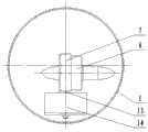
图1为本发明的一个具体实施方案的主剖示意图;Fig. 1 is the main sectional view of a specific embodiment of the present invention;
图2为本发明的一个具体实施方案的侧剖示意图;Fig. 2 is a schematic side sectional view of a specific embodiment of the present invention;
图3为本发明的一个具体实施方案的网笼状球壳的三维图;Fig. 3 is a three-dimensional view of a cage-shaped spherical shell of a specific embodiment of the present invention;
图4为本发明第二种实施方案,涵道风扇中心连线位于水平中心线以上安装侧剖示意图;Fig. 4 is a second embodiment of the present invention, where the central connection line of the ducted fan is located above the horizontal centerline and is installed in a side sectional view;
图5为本发明第三种实施方案,涵道风扇中心连线位于水平中心线以下安装侧剖示意图;Fig. 5 is a third embodiment of the present invention, where the central connection line of the ducted fan is located below the horizontal centerline and is installed in a side sectional view;
图6为本发明第四种实施方案,涵道风扇与水平面成一定角度安装侧剖示意图。Fig. 6 is a schematic side sectional view of the fourth embodiment of the present invention, where the ducted fan is installed at a certain angle to the horizontal plane.
具体实施方式Detailed ways
如图1、图2、图3所示,本发明的一个实施例为:喷气式球形机器人由球壳1和内部运动机构组成。内部运动机构与球壳1之间通过左轴承10和右轴承3分别左右连接,内部运动机构和球壳之间能够绕着水平中心线相对转动。球壳1由纬度圆环15、经度圆环16、17、18以及左轴承安装座2、右轴承安装座9组成。纬度圆环15个数N1>=4个,绕着水平中心线成放射状等角度分布;经度圆环个数N2>=1,并且沿纵剖面对称分布;左轴承座9和右轴承座2沿着纵剖面对称等距地固定在球壳内部左右两边。内部运动机构由支撑架7、左涵道风扇12、右涵道风扇6、重锤14、刚性杆件13以及固定在支撑架上的左短轴11、右短轴4组成。左涵道风扇12、右涵道风扇6通过支撑架7上的左右涵道风扇安装座,沿着纵剖面等距的安装在纵剖面左右两侧,两个涵道风扇的中心连线位于水平中心线上;重锤14通过刚性杆件13连接在支撑架7上,位于球壳纵剖面上;左短轴11套在左轴承10内圈中,右短轴4套在右轴承3内圈中。由于重锤的作用,机器人整体重心在水平中心线以下,机器人具有自稳定性。运动时候,当左右涵道风扇12、6产生相同推力时,推力推动内部运动机构绕着水平中心线偏转,机器人整体重心位置改变,球壳绕着水平中心线转动,实现机器人前进运动;当左右涵道风扇12、6转速不同,产生大小不同推力时,机器人在前进运动同时还产生偏转运动,实现机器人的转向。As shown in Fig. 1, Fig. 2 and Fig. 3, one embodiment of the present invention is: the jet-type spherical robot is made up of
如图4所示,本发明的第二种实施例为:左涵道风扇12、右涵道风扇6的中心连线位于球壳1水平中心线线以上,其他机构与功能与实施例1相似。As shown in Figure 4, the second embodiment of the present invention is: the center connection line of the left ducted fan 12 and the right ducted
如图5所示,本发明的第三种实施例为:左涵道风扇12、右涵道风扇6的中心连线位于球壳1水平中心线线以下,其他机构与功能与实施例1相似。As shown in Figure 5, the third embodiment of the present invention is: the center connecting line of the left ducted fan 12 and the right ducted
如图6所示,本发明的第四种实施例为:两个涵道风扇6、12的安装角与水平面成一定角度θ,其他机构与功能与实施例1相似。运动时候,风扇部分推力分量抵消球形机器人部分甚至全部重力,其余推力分量推动球型机器人,实现“漂浮式”前进运动。As shown in Figure 6, the fourth embodiment of the present invention is: the installation angle of the two
Claims (7)
Translated fromChinesePriority Applications (1)
| Application Number | Priority Date | Filing Date | Title |
|---|---|---|---|
| CN201310378865.7ACN103465992B (en) | 2013-08-27 | 2013-08-27 | Jet spherical robot |
Applications Claiming Priority (1)
| Application Number | Priority Date | Filing Date | Title |
|---|---|---|---|
| CN201310378865.7ACN103465992B (en) | 2013-08-27 | 2013-08-27 | Jet spherical robot |
Publications (2)
| Publication Number | Publication Date |
|---|---|
| CN103465992Atrue CN103465992A (en) | 2013-12-25 |
| CN103465992B CN103465992B (en) | 2016-04-06 |
Family
ID=49791100
Family Applications (1)
| Application Number | Title | Priority Date | Filing Date |
|---|---|---|---|
| CN201310378865.7AExpired - Fee RelatedCN103465992B (en) | 2013-08-27 | 2013-08-27 | Jet spherical robot |
Country Status (1)
| Country | Link |
|---|---|
| CN (1) | CN103465992B (en) |
Cited By (10)
| Publication number | Priority date | Publication date | Assignee | Title |
|---|---|---|---|---|
| CN104608152A (en)* | 2015-01-30 | 2015-05-13 | 东莞市李群自动化技术有限公司 | Integrated robot with efficient heat dissipating device |
| CN104908964A (en)* | 2014-06-06 | 2015-09-16 | 苏州晓炎自动化设备有限公司 | Spherical robot |
| CN104965430A (en)* | 2015-06-29 | 2015-10-07 | 广州杰赛科技股份有限公司 | Environment detection device, power supply control method thereof and emergency monitoring system |
| CN106080837A (en)* | 2016-08-18 | 2016-11-09 | 杭州骑客智能科技有限公司 | A kind of big wheelbarrow |
| CN106114620A (en)* | 2016-08-18 | 2016-11-16 | 杭州骑客智能科技有限公司 | Big wheelbarrow |
| CN110524521A (en)* | 2019-09-11 | 2019-12-03 | 孙文卿 | A kind of transfer of intellect service robot |
| CN110920773A (en)* | 2019-12-06 | 2020-03-27 | 张占锁 | Rolling off-road device |
| CN113492936A (en)* | 2021-08-02 | 2021-10-12 | 天津大学 | Trolley with air injection auxiliary power mechanism and control method thereof |
| CN113650691A (en)* | 2021-08-30 | 2021-11-16 | 西安交通大学 | All-terrain obstacle-crossing spherical robot |
| CN114536352A (en)* | 2020-11-27 | 2022-05-27 | 三赢科技(深圳)有限公司 | Mechanical positioning structure and manipulator assembly |
Citations (5)
| Publication number | Priority date | Publication date | Assignee | Title |
|---|---|---|---|---|
| US4505346A (en)* | 1982-03-29 | 1985-03-19 | Leonard E. Mueller | Rolling vehicle |
| GB2165196A (en)* | 1984-10-09 | 1986-04-09 | Dr Taha Khalil Aldoss | Spherical vehicle |
| US20030025032A1 (en)* | 2000-02-15 | 2003-02-06 | Bertin Technologies | Remote controlled aircraft, in particular for surveillance or inspection |
| CN1550192A (en)* | 2003-03-05 | 2004-12-01 | ������������ʽ���� | Self-propelled cleaning machine and charging device used therein |
| CN201313307Y (en)* | 2008-11-10 | 2009-09-23 | 战强 | Spherical environment detection robot |
- 2013
- 2013-08-27CNCN201310378865.7Apatent/CN103465992B/ennot_activeExpired - Fee Related
Patent Citations (5)
| Publication number | Priority date | Publication date | Assignee | Title |
|---|---|---|---|---|
| US4505346A (en)* | 1982-03-29 | 1985-03-19 | Leonard E. Mueller | Rolling vehicle |
| GB2165196A (en)* | 1984-10-09 | 1986-04-09 | Dr Taha Khalil Aldoss | Spherical vehicle |
| US20030025032A1 (en)* | 2000-02-15 | 2003-02-06 | Bertin Technologies | Remote controlled aircraft, in particular for surveillance or inspection |
| CN1550192A (en)* | 2003-03-05 | 2004-12-01 | ������������ʽ���� | Self-propelled cleaning machine and charging device used therein |
| CN201313307Y (en)* | 2008-11-10 | 2009-09-23 | 战强 | Spherical environment detection robot |
Cited By (13)
| Publication number | Priority date | Publication date | Assignee | Title |
|---|---|---|---|---|
| CN104908964A (en)* | 2014-06-06 | 2015-09-16 | 苏州晓炎自动化设备有限公司 | Spherical robot |
| CN104608152A (en)* | 2015-01-30 | 2015-05-13 | 东莞市李群自动化技术有限公司 | Integrated robot with efficient heat dissipating device |
| CN104965430A (en)* | 2015-06-29 | 2015-10-07 | 广州杰赛科技股份有限公司 | Environment detection device, power supply control method thereof and emergency monitoring system |
| CN106080837A (en)* | 2016-08-18 | 2016-11-09 | 杭州骑客智能科技有限公司 | A kind of big wheelbarrow |
| CN106114620A (en)* | 2016-08-18 | 2016-11-16 | 杭州骑客智能科技有限公司 | Big wheelbarrow |
| CN110524521A (en)* | 2019-09-11 | 2019-12-03 | 孙文卿 | A kind of transfer of intellect service robot |
| CN110920773A (en)* | 2019-12-06 | 2020-03-27 | 张占锁 | Rolling off-road device |
| CN110920773B (en)* | 2019-12-06 | 2021-07-20 | 张占锁 | Rolling off-road device |
| CN114536352A (en)* | 2020-11-27 | 2022-05-27 | 三赢科技(深圳)有限公司 | Mechanical positioning structure and manipulator assembly |
| CN114536352B (en)* | 2020-11-27 | 2023-09-12 | 三赢科技(深圳)有限公司 | Mechanical positioning structure and manipulator assembly |
| CN113492936A (en)* | 2021-08-02 | 2021-10-12 | 天津大学 | Trolley with air injection auxiliary power mechanism and control method thereof |
| CN113492936B (en)* | 2021-08-02 | 2023-03-14 | 天津大学 | Trolley with air injection auxiliary power mechanism and control method thereof |
| CN113650691A (en)* | 2021-08-30 | 2021-11-16 | 西安交通大学 | All-terrain obstacle-crossing spherical robot |
Also Published As
| Publication number | Publication date |
|---|---|
| CN103465992B (en) | 2016-04-06 |
Similar Documents
| Publication | Publication Date | Title |
|---|---|---|
| CN103465992B (en) | Jet spherical robot | |
| JP5812849B2 (en) | Small drone | |
| CN103358839A (en) | Amphibious spherical exploration robot | |
| CN104527352A (en) | Novel spherical amphibious robot and working method thereof | |
| CN105835640A (en) | Three degree-of-freedom attitude control device, system and method | |
| CN102407890A (en) | Spherical moving device with enhanced function | |
| CN107985580B (en) | A multi-modal deformable rotor robot | |
| CN111672081B (en) | A five-degree-of-freedom continuous load simulation platform | |
| CN103712035A (en) | Cage type pipeline aircraft | |
| CN103895726A (en) | Novel full-symmetric spherical robot | |
| CN104192324B (en) | The synchronous space three-dimensional simulator of swing arm type rotation | |
| CN104616562B (en) | Rail type flight simulator having continuous overload simulation capability | |
| CN101372259A (en) | Anti-gravity method and anti-gravity device thereof used as dish form multiway aerial craft for rotating and stopping in air | |
| CN104616563A (en) | Rocker arm type flight simulator having continuous overload simulation capability | |
| CN204056041U (en) | Climbing robot omni-directional wheel chassis | |
| CN102069908A (en) | Saucer type aircraft | |
| CN1318190C (en) | Omnibearing movable spherical robot | |
| CN103213681B (en) | Six-degree-of-freedofour-shaft four-shaft aircraft | |
| Zhang et al. | A centimeter-scale electrohydrodynamic multi-modal robot capable of rolling, hopping, and taking off | |
| CN102616377A (en) | Tai chi flying saucer | |
| CN100556621C (en) | An omnidirectional rolling spherical robotic device with a stable platform | |
| CN102582833A (en) | Flying saucer in shape of tai chi | |
| CN102152850A (en) | Saucer type aircraft | |
| CN212735999U (en) | Structure for optimizing motion efficiency of snake-shaped robot | |
| CN1739924A (en) | Self-supporting dynamic balancing mobile robot |
Legal Events
| Date | Code | Title | Description |
|---|---|---|---|
| C06 | Publication | ||
| PB01 | Publication | ||
| C10 | Entry into substantive examination | ||
| SE01 | Entry into force of request for substantive examination | ||
| C14 | Grant of patent or utility model | ||
| GR01 | Patent grant | ||
| CF01 | Termination of patent right due to non-payment of annual fee | Granted publication date:20160406 |