CN103458966A - Irradiation equipment and control method for controlling it - Google Patents
Irradiation equipment and control method for controlling itDownload PDFInfo
- Publication number
- CN103458966A CN103458966ACN2012800153307ACN201280015330ACN103458966ACN 103458966 ACN103458966 ACN 103458966ACN 2012800153307 ACN2012800153307 ACN 2012800153307ACN 201280015330 ACN201280015330 ACN 201280015330ACN 103458966 ACN103458966 ACN 103458966A
- Authority
- CN
- China
- Prior art keywords
- measuring
- irradiation
- particle
- monitoring device
- range
- Prior art date
- Legal status (The legal status is an assumption and is not a legal conclusion. Google has not performed a legal analysis and makes no representation as to the accuracy of the status listed.)
- Granted
Links
Images


Classifications
- H—ELECTRICITY
- H01—ELECTRIC ELEMENTS
- H01J—ELECTRIC DISCHARGE TUBES OR DISCHARGE LAMPS
- H01J37/00—Discharge tubes with provision for introducing objects or material to be exposed to the discharge, e.g. for the purpose of examination or processing thereof
- H01J37/30—Electron-beam or ion-beam tubes for localised treatment of objects
- H01J37/304—Controlling tubes by information coming from the objects or from the beam, e.g. correction signals
- A—HUMAN NECESSITIES
- A61—MEDICAL OR VETERINARY SCIENCE; HYGIENE
- A61N—ELECTROTHERAPY; MAGNETOTHERAPY; RADIATION THERAPY; ULTRASOUND THERAPY
- A61N5/00—Radiation therapy
- A61N5/10—X-ray therapy; Gamma-ray therapy; Particle-irradiation therapy
- A61N5/1048—Monitoring, verifying, controlling systems and methods
- A61N5/1064—Monitoring, verifying, controlling systems and methods for adjusting radiation treatment in response to monitoring
- A61N5/1065—Beam adjustment
- A61N5/1067—Beam adjustment in real time, i.e. during treatment
- H—ELECTRICITY
- H01—ELECTRIC ELEMENTS
- H01J—ELECTRIC DISCHARGE TUBES OR DISCHARGE LAMPS
- H01J37/00—Discharge tubes with provision for introducing objects or material to be exposed to the discharge, e.g. for the purpose of examination or processing thereof
- H01J37/30—Electron-beam or ion-beam tubes for localised treatment of objects
- H01J37/317—Electron-beam or ion-beam tubes for localised treatment of objects for changing properties of the objects or for applying thin layers thereon, e.g. for ion implantation
- A—HUMAN NECESSITIES
- A61—MEDICAL OR VETERINARY SCIENCE; HYGIENE
- A61N—ELECTROTHERAPY; MAGNETOTHERAPY; RADIATION THERAPY; ULTRASOUND THERAPY
- A61N5/00—Radiation therapy
- A61N5/10—X-ray therapy; Gamma-ray therapy; Particle-irradiation therapy
- A61N2005/1085—X-ray therapy; Gamma-ray therapy; Particle-irradiation therapy characterised by the type of particles applied to the patient
- A61N2005/1087—Ions; Protons
- A—HUMAN NECESSITIES
- A61—MEDICAL OR VETERINARY SCIENCE; HYGIENE
- A61N—ELECTROTHERAPY; MAGNETOTHERAPY; RADIATION THERAPY; ULTRASOUND THERAPY
- A61N5/00—Radiation therapy
- A61N5/10—X-ray therapy; Gamma-ray therapy; Particle-irradiation therapy
- A61N5/1042—X-ray therapy; Gamma-ray therapy; Particle-irradiation therapy with spatial modulation of the radiation beam within the treatment head
- A61N5/1043—Scanning the radiation beam, e.g. spot scanning or raster scanning
- A61N5/1044—Scanning the radiation beam, e.g. spot scanning or raster scanning with multiple repetitions of the scanning pattern
Landscapes
- Health & Medical Sciences (AREA)
- Engineering & Computer Science (AREA)
- Biomedical Technology (AREA)
- Chemical & Material Sciences (AREA)
- Analytical Chemistry (AREA)
- Nuclear Medicine, Radiotherapy & Molecular Imaging (AREA)
- Life Sciences & Earth Sciences (AREA)
- Animal Behavior & Ethology (AREA)
- General Health & Medical Sciences (AREA)
- Public Health (AREA)
- Veterinary Medicine (AREA)
- Radiology & Medical Imaging (AREA)
- Pathology (AREA)
- Radiation-Therapy Devices (AREA)
- Measurement Of Radiation (AREA)
- Particle Accelerators (AREA)
Abstract
Description
Translated fromChinese技术领域technical field
本发明涉及一种辐照设备,其具有粒子加速器,借助粒子加速器可产生粒子束,可借助射束监控装置监控该粒子束的射束强度。本发明还涉及一种用于控制这种辐照设备的控制方法。本发明的实施方式尤其是用于粒子治疗领域中,在粒子治疗中例如对患者进行辐照。The invention relates to an irradiation installation having a particle accelerator, by means of which a particle beam can be generated, the beam intensity of which can be monitored by means of a beam monitoring device. The invention also relates to a control method for controlling such an irradiation installation. Embodiments of the invention are used in particular in the field of particle therapy in which, for example, patients are irradiated.
背景技术Background technique
粒子治疗是一种为了治疗组织、尤其是肿瘤病症而建立的方法。但,例如在粒子治疗中被采用的辐照方法也被应用于非治疗的领域中。这例如包括研究工作、例如对非活体模或体进行的粒子治疗(如辐照材料等)的范围内进行的产品开发。Particle therapy is a method established for the treatment of tissues, especially neoplastic conditions. However, the irradiation methods used, for example, in particle therapy are also used in non-therapeutic fields. This includes, for example, product development within the scope of research work, eg particle therapy on non-living phantoms or bodies (eg irradiation materials etc.).
在此,将例如质子或碳离子或其它离子的带电粒子加速到高能、成形为粒子束并且通过高能束传输系统输送到一个或多个辐照空间。在辐照空间中利用粒子束辐照待辐照的靶区。Here, charged particles such as protons or carbon ions or other ions are accelerated to high energies, shaped into a particle beam and delivered to one or more irradiation spaces by means of a high-energy beam delivery system. The target area to be irradiated is irradiated with the particle beam in the irradiation space.
为了确保辐照的成功和辐照可靠性,持续监控粒子束的射束质量。To ensure the success of the irradiation and the reliability of the irradiation, the beam quality of the particle beam is continuously monitored.
这例如借助射束监控系统来进行,在其中不仅使用强度测量室而且使用位置测量室。两种测量通常冗余进行,从而在两个系统之一故障时总是存在第二监控级(Instanz)。由此提高了射束施加时的可靠性。This is done, for example, by means of a beam monitoring system, in which both an intensity-measuring chamber and a position-measuring chamber are used. Both measurements are usually carried out redundantly, so that if one of the two systems fails, there is always a second monitoring level (Instanz). This increases the reliability during beam application.
强度测量室例如可用于光栅扫描方法中的辐照控制。在光栅扫描方法中,粒子束依次扫过靶区中的大量靶点并且沉积预先规定的粒子数。借助强度测量室于是监控通过射束沉积的粒子数作为射束质量,使得一旦在当前靶点上沉积所需的粒子数,则可控制粒子束移向下一靶点。The intensity measurement chamber can be used, for example, for irradiation control in raster scanning methods. In the raster scanning method, a particle beam is sequentially scanned over a large number of targets in a target volume and deposits a predetermined number of particles. With the aid of the intensity measuring cell, the number of particles deposited by the beam is then monitored as beam quality, so that once the desired number of particles has been deposited at the current target point, the movement of the particle beam to the next target point can be controlled.
射束强度的测量例如在强度较低时通过测量室的信号噪声比并且在强度较高时通过测量室的可能的饱和受到限制。由于要测量粒子束的射束质量的范围大,所以测量室或放大器或测量链中的其它对室中所产生的电荷进行检测的仪器通常具有多个测量范围。The measurement of the beam intensity is limited, for example, by the signal-to-noise ratio of the measurement chamber at low intensities and by possible saturation of the measurement chamber at high intensities. Due to the large range over which the beam quality of the particle beam is to be measured, the measuring chamber or the amplifier or other devices in the measuring chain which detect the charges generated in the chamber usually have a plurality of measuring ranges.
靶区的辐照可在等能量层中进行。靶区在此被分为等能量层,为每个等能量层分别配置一个粒子束能量。通过使粒子束能量适配相应待辐照的等能量层依次进行等能量层的辐照。Irradiation of the target area can be carried out in the equal energy layer. The target area is divided into equal-energy layers, and a particle beam energy is assigned to each equal-energy layer. The iso-energy layers are irradiated sequentially by adapting the energy of the particle beam to the corresponding iso-energy layer to be irradiated.
发明内容Contents of the invention
本发明的任务在于提供一种辐照设备,其实现更可靠地辐照靶区,同时更有利和迅速地激励辐照设备。本发明的任务还在于给出一种相应的用于进行辐照的控制方法。The object of the present invention is to provide an irradiation device which enables a more reliable irradiation of the target area and at the same time a more favorable and rapid excitation of the irradiation device. It is also the object of the invention to specify a corresponding control method for the irradiation.
所述任务通过独立权利要求来解决。本发明优选的实施方式在从属权利要求中给出并且在下面做进一步说明。对各个特征的上述以及下述的描述既涉及装置类别也涉及方法类别,而无需在每种情况下个别地明确指出这点。在此所公开的各个特征也可在与所示组合不同的组合中成为对本发明而言重要的。This task is solved by the independent claims. Preferred embodiments of the invention are given in the dependent claims and are further explained below. The above and below descriptions of the individual features relate both to the device category and to the method category, without this needing to be explicitly stated in each case individually. Individual features disclosed here can also be essential to the invention in combinations other than those shown.
根据本发明的辐照设备包括:The irradiation device according to the invention comprises:
-具有粒子加速器的加速器装置,借助粒子加速器可加速粒子并且借助其可产生粒子束,该粒子束具有射束强度,- an accelerator device having a particle accelerator, by means of which particles can be accelerated and by means of which a particle beam can be generated, the particle beam having a beam intensity,
-至少一个用于测量粒子束射束质量的射束监控装置,该射束监控装置具有多个可设置的测量范围,- at least one beam monitoring device for measuring the beam quality of the particle beam, which beam monitoring device has a plurality of adjustable measuring ranges,
-用于控制加速器装置和射束监控装置的控制装置,- control devices for controlling accelerator devices and beam monitoring devices,
其中,射束监控装置的测量范围可根据粒子束的射束强度和/或待施加的粒子数被设置并且尤其在辐照期间进行改变。In this case, the measuring range of the beam monitoring device can be set and changed in particular during irradiation as a function of the beam intensity of the particle beam and/or the number of particles to be applied.
由射束监控装置所测量的射束质量尤其是射束强度和/或横向射束位置。The beam quality measured by the beam monitoring device is in particular the beam intensity and/or the transverse beam position.
本发明基于下述认识:在目前的辐照设备或辐照方法中始终须确保也可精确监控待施加的剂量。这以下述方式来实现,即,基于通过治疗计划预给定的特定要求来设置粒子束的强度和射束监控装置的测量范围。然后借助所述设置来辐照靶区。The invention is based on the recognition that in current irradiation installations or irradiation methods it must always be ensured that the dose to be administered can also be precisely monitored. This is achieved by setting the intensity of the particle beam and the measuring range of the beam monitoring device on the basis of the specific requirements specified by the treatment plan. The target volume is then irradiated with the aid of this setup.
但已经认识到,该刚性的预给定导致辐照设备的控制不利。例如应根据辐照计划使用强度较低的射束并且必须与其对应地设置射束监控装置的测量范围,因为例如在治疗计划中存在具有较少粒子数的靶点,从而在该靶点中只能通过该设置可靠地确保剂量沉积的监控。但这意味着,也要以该设置扫过治疗计划的其它靶点、即其上沉积明显更多的粒子数的靶点。因此这导致相对长的辐照持续时间。However, it has been found that this rigid specification leads to disadvantages in the control of the irradiation system. For example, depending on the irradiation plan, a lower intensity beam is to be used and the measuring range of the beam monitoring device must be adjusted accordingly, because for example, in the treatment plan there are target points with a lower particle number, so that only Monitoring of dose deposition can be reliably ensured by this arrangement. However, this means that other target points of the treatment plan, ie target points on which a significantly higher number of particles are deposited, are also swept over with this setting. This therefore results in a relatively long duration of irradiation.
现在已认识到,当例如通过控制装置控制设备来在辐照期间改变射束监控系统的有效测量范围的选择时,可更加灵活地设计该方法。所述改变例如可根据相应待施加的粒子数进行和/或根据可设置的射束强度进行。It has now been realized that the method can be designed more flexibly when the selection of the effective measuring range of the beam monitoring system is changed during irradiation, for example by the control device controlling the device. The change can take place, for example, as a function of the respective number of particles to be applied and/or as a function of a settable beam intensity.
如待施加的粒子数在确定的辐照区段中较少或射束强度较小,则在射束监控装置中激发相对少的电荷。为了正确测量射束质量需要将在射束监控装置中激发的信号放大较高。相反,当待施加的粒子数或射束强度高时,则激发相对多的电荷。为了正确测量射束质量,需要将在射束监控装置中激发的信号放大较低、即射束监控装置的另一测量范围。尤其是根据粒子束的射束强度和/或待施加的粒子数例如借助可开关的放大器链来改变在射束监控装置中被激发的信号的放大。If the number of particles to be applied is lower in a defined irradiation section or the beam intensity is lower, relatively few electrical charges are excited in the beam monitoring device. A high amplification of the signal excited in the beam monitoring device is required for correct measurement of the beam quality. Conversely, when the number of particles to be applied or the beam intensity is high, relatively many charges are excited. In order to measure the beam quality correctly, the signal excited in the beam monitoring device needs to be amplified lower, ie another measuring range of the beam monitoring device. In particular, the amplification of the signal excited in the beam monitoring device is varied depending on the beam intensity of the particle beam and/or the number of particles to be applied, for example by means of a switchable amplifier chain.
辐照可更快地进行,因为粒子束和因此为正确监控射束所需的测量范围可在辐照期间、即在射束被施加到靶区上期间适配待施加的粒子数。因此通过本发明可显著减少辐照时间。Irradiation can be performed faster because the particle beam and thus the measuring range required for correct monitoring of the beam can be adapted to the number of particles to be applied during the irradiation, ie while the beam is applied to the target region. The irradiation time can thus be significantly reduced by the invention.
在一种有利的实施形式中,控制装置可构造用于以扫描方法对靶区进行辐照,可至少暂时在辐照靶区期间根据靶区中每靶点待施加的粒子数设置测量范围。In an advantageous embodiment, the control device can be designed to irradiate the target volume in a scanning manner, and the measurement range can be set at least temporarily during the irradiation of the target volume as a function of the number of particles to be applied per target point in the target volume.
通过这种方式例如总是在如下情况下才转换测量范围,即通过该转换能够更快地辐照之后待辐照的靶点。测量范围的设置可保持直至必须扫过一个新的靶点,该靶点要求测量范围的适配。这例如可出现在借助目前设置的测量范围不再能确保为新靶点可靠地施加剂量时。根据通常由加速器装置预给定的切换持续时间,可能需要在关键的需要切换的靶点之前已经切换该适配。In this way, for example, the measuring range is only switched only when the target point to be irradiated later can be irradiated faster by this switching. The setting of the measuring range remains until a new target point has to be scanned, which requires an adaptation of the measuring range. This can occur, for example, when a reliable application of a dose for a new target can no longer be ensured by means of the currently set measuring range. Depending on the switching duration, which is generally predetermined by the accelerator device, it may be necessary to switch the adaptation already before the critical target point to be switched.
在另一种有利的实施形式中,控制装置可构造用于在等能量层中逐层对靶区进行辐照。在此情况下可将控制装置构造为,使得射束监控装置的测量范围可在一个等能量层的辐照期间进行改变。由此不仅可从等能量层到等能量层地、而且也可在一个等能量层内最佳地适配辐照。在此已发现,不仅从等能量层到等能量层而且在一个等能量层内已会出现待施加的粒子数的大波动。In another advantageous embodiment, the control device can be designed to irradiate the target region layer by layer in the isoenergy layer. In this case, the control device can be designed such that the measuring range of the beam monitoring device can be changed during the irradiation of an isoenergy layer. As a result, the irradiation can be optimally adapted not only from iso-energy layer to iso-energy layer, but also within an iso-energy layer. It has been found here that large fluctuations in the number of particles to be applied already occur not only from isoenergy layer to isoenergy layer but also within an isoenergy layer.
在另一种有利的实施方式中,控制装置可构造用于以再扫描方法进行辐照。在这种辐照方法中,在一次辐照治疗时以多个依次的再扫描遍历辐照靶区的数个区域。射束监控装置的测量范围可在一个再扫描遍历内进行改变。In a further advantageous embodiment, the control device can be designed to carry out the irradiation in a rescanning method. In this irradiation method, several regions of the irradiation target volume are traversed in a plurality of successive rescans during one irradiation treatment. The measuring range of the beam monitoring device can be changed within a rescanning pass.
再扫描方法在此是一种特殊方法,其用于辐照移动的靶区。在此在一次辐照治疗中通过未校正地多次应用用于计划靶区(参见ICRU)的辐照计划在每次施加成比例减少的剂量的情况下沉积总剂量,该总剂量平均与临床靶区(参见ICRU)的期望剂量分布一致,因为通过多次辐照的次数在很大程度上平均了由于靶区运动引起的有错误的剂量沉积。The rescanning method is a special method here, which is used to irradiate moving target volumes. The irradiation plan for planning the target volume (see ICRU) by uncorrected multiple applications in one irradiation treatment deposits a total dose with each application of a proportionally reduced dose, which on average corresponds to the clinical The desired dose distribution in the target volume (see ICRU) is consistent because the number of passes through multiple irradiations largely averages out erroneous dose deposition due to target volume motion.
但与传统辐照相比通过每次再扫描遍历成比例减小的剂量在射束监控装置中所激发的载流子明显更少。现在已认识到,在刚性预给定辐照强度/测量范围的情况下在再扫描方法中这恰恰导致明显更长的辐照时间。在这方面根据本发明的构造用于实施再扫描方法的辐照设备尤为有利,因为现在通过灵活适配射束监控装置的测量范围可在辐照速度方面实现明显的优势。即在没有根据本发明的方案的情况下,在再扫描方法中辐照时间因而非常长。但已经发现,只有当靶区运动的所有运动阶段不协调于粒子束的运动时,再扫描才能很好地作用。因此,一旦辐照持续时间位于靶区运动的量级中,减缓的辐照又部分减弱了再扫描方法中的平均效果。Compared to conventional irradiation, however, significantly fewer charge carriers are excited in the beam monitoring device by the proportionally reduced dose per rescanning pass. It has now been found that, with a rigid specification of the irradiation intensity/measuring range, this leads precisely to significantly longer irradiation times in the rescanning method. In this respect, an irradiation installation designed according to the invention for carrying out the rescanning method is particularly advantageous, since a clear advantage in terms of irradiation speed can now be achieved by flexibly adapting the measuring range of the beam monitoring device. That is to say, without the solution according to the invention, the irradiation time would therefore be very long in the rescanning method. However, it has been found that rescanning works well only when all motion phases of the target motion are uncoordinated with the motion of the particle beam. Thus, once the irradiation duration is in the order of the target volume motion, the slowed irradiation in turn partially attenuates the averaging effect in the rescanning method.
现在尤其可灵活控制粒子束的射束强度、例如通过控制同步加速器中的提取机构或通过控制回旋加速器中由源提供的射束强度并且与此对应地在辐照期间灵活选择测量范围。这样例如可在辐照期间尤其是基于存储于辐照计划中的每靶点的粒子数改变射束强度,并且在辐照期间当射束强度从第一测量范围离开和/或进入第二测量范围中时将测量装置从第一测量范围切换到第二测量范围中。In particular, the beam intensity of the particle beam can now be flexibly controlled, for example by controlling the extraction mechanism in the synchrotron or by controlling the beam intensity provided by the source in the cyclotron and correspondingly flexibly selecting the measurement range during the irradiation. In this way, for example, the beam intensity can be varied during the irradiation, in particular based on the number of particles per target point stored in the irradiation plan, and when the beam intensity leaves the first measurement range and/or enters the second measurement range during the irradiation In range switches the measuring device from the first measuring range to the second measuring range.
在此可这样构造辐照设备,使得(当需要切换测量范围时)短时中断粒子束并且在射束中断时切换测量范围。通过这种方式避免在如下时刻施加射束,在该时刻期间没有提供测量范围来监控射束质量。通过这种方式例如可在强度测量室的情况下确保始终进行电荷积分并且因此可精确监控放射性剂量测定法。In this case, the irradiation system can be designed in such a way that the particle beam is briefly interrupted (when a changeover of the measurement range is required) and the measurement range is switched when the beam is interrupted. In this way, it is avoided that the beam is applied at times during which no measuring range is available for monitoring the beam quality. In this way, for example in the case of an intensity measuring chamber, charge integration can be ensured at all times and thus precise monitoring of the radioactive dosimetry can be performed.
但并非必须如此。测量范围的切换也可在射束施加或者在粒子束接通时进行。在此情况下,虽然原则上存在例如在强度监控时无法检测全部射束的风险,但当测量范围切换的持续时间足够小和/或仅施加小强度的射束时,射束监控时产生的不精确性也可处于可容许的范围内。But it doesn't have to be. The switching of the measuring range can also take place when the beam is applied or when the particle beam is switched on. In this case, although in principle there is the risk, for example, that the entire beam cannot be detected during intensity monitoring, if the duration of the measurement range switchover is sufficiently short and/or only low-intensity beams are applied, the resulting Imprecision may also be within a tolerable range.
在一种有利的实施形式中,射束监控装置包括至少两个测量装置,借助它们可分别测量同一射束质量。所述测量装置例如可用于冗余测量射束质量、例如射束强度或横向射束位置。测量装置本身分别具有不同的测量范围,并且测量装置可设置为,使得其至少暂时在不同的测量范围中工作。其优点在于,可改善射束监控装置的测量范围的切换,因为在射束监控装置内已经存在不同的、同时有效的测量范围。快速切换例如可通过从一个测量装置(其在第一测量范围中工作)转换到另一测量装置(其在第二测量范围中工作)来实现,而在射束监控中不会出现明显或者说成问题的间隙。In an advantageous embodiment, the beam monitoring device comprises at least two measuring devices, by means of which the same beam quality can be measured in each case. The measuring device can be used, for example, for redundant measurement of beam qualities, such as beam intensity or lateral beam position. The measuring devices themselves each have different measuring ranges, and the measuring devices can be arranged in such a way that they operate at least temporarily in different measuring ranges. This has the advantage that switching over the measuring ranges of the beam monitoring device can be improved, since different simultaneously active measuring ranges already exist within the beam monitoring device. Rapid switching can be achieved, for example, by switching from one measuring device (which operates in a first measuring range) to another measuring device (which operates in a second measuring range) without significant or obvious changes in the beam monitoring. problematic gap.
在一种方案中,测量装置之一可作为主测量装置工作而另一测量装置可作为冗余测量装置工作。主测量装置和冗余测量装置可在不同的测量范围中工作。例如主测量装置可在最佳地匹配希望的射束质量的测量范围中工作,而冗余测量装置则在相邻的测量范围中、即在非理想的测量范围中工作。但由此可实现的较小的精度对于冗余测量而言是足够的,因为仍可检验所施加剂量的量级并且因此在重大错误计量时可关断射束。但当必须转换测量范围时,具有另一测量范围的测量装置已经活动。由此可容易且简单地实现切换。In one variant, one of the measuring devices can be operated as a master measuring device and the other measuring device can be operated as a redundant measuring device. The main measuring device and the redundant measuring device can work in different measuring ranges. For example, the main measuring device can be operated in a measuring range that is optimally adapted to the desired beam quality, while the redundant measuring device can be operated in an adjacent measuring range, ie in a non-ideal measuring range. However, the lower precision achievable in this way is sufficient for redundant measurements, since the magnitude of the applied dose can still be checked and the beam can thus be switched off in the event of a gross misdosing. However, when the measuring range has to be switched, a measuring device with another measuring range is already active. Switching can thus be realized easily and simply.
如必须切换射束监控装置的测量范围,可在多个测量装置的情况下依次切换各测量装置的测量范围。通过这种方式可进行连续测量,仅在相应短时的切换时间中省去了冗余测量。If it is necessary to switch the measuring range of the beam monitoring device, in the case of several measuring devices the measuring ranges of the individual measuring devices can be switched successively. Continuous measurements are possible in this way, redundant measurements being dispensed with only for correspondingly short switching times.
根据本发明的用于控制辐照设备的控制方法包括下述步骤:A control method for controlling an irradiation device according to the present invention comprises the following steps:
-产生粒子束,该粒子束具有射束强度,- generating a particle beam having a beam intensity,
-借助射束监控装置监控粒子束的射束质量,从多个可设置的测量范围中选择一个测量范围,其中,尤其是根据粒子束的射束强度和/或根据待施加的粒子数设置射束监控装置的测量范围并且在辐照期间改变测量范围。- monitoring the beam quality of the particle beam by means of a beam monitoring device, selecting a measuring range from a plurality of settable measuring ranges, wherein in particular the beam intensity is set according to the beam intensity of the particle beam and/or according to the number of particles to be applied The measurement range of the beam monitoring device and changes the measurement range during irradiation.
附图说明Description of drawings
下面借助附图详细说明具有根据从属权利要求特征的扩展方案的本发明的实施形式,但本发明并不局限于此。附图如下:Embodiments of the invention with developments according to the features of the dependent claims are explained in detail below with reference to the drawings, without the invention being restricted thereto. The accompanying drawings are as follows:
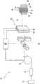
图1为粒子治疗设备的示意图,在其中辐照包括多个设置在等能量层中的靶点的靶区;Figure 1 is a schematic diagram of a particle therapy apparatus in which a target volume comprising a plurality of targets arranged in iso-energy layers is irradiated;
图2为变化的粒子数分布的视图,其应被施加于一个等能量层内的并排的靶点上;Figure 2 is a view of varying population distributions that should be applied to side-by-side targets within an equal-energy layer;
图3为用于说明射束监控装置的测量范围与粒子束的强度对应的视图;3 is a view for explaining that the measurement range of the beam monitoring device corresponds to the intensity of the particle beam;
图4为类似于图3的视图,其示出测量范围切换期间短时的射束中断;FIG. 4 is a view similar to FIG. 3, showing a brief beam interruption during a measurement range changeover;
图5为说明一种实施形式的视图,其在射束监控装置中采用两个测量装置来监控射束质量;5 is a view illustrating an embodiment in which two measuring devices are used in the beam monitoring device to monitor the beam quality;
图6为另一种实施形式的视图,其采用两个测量装置,Fig. 6 is the view of another embodiment, it adopts two measuring devices,
图7为用于实施该方法的方法步骤示意图。Figure 7 is a schematic diagram of method steps for implementing the method.
具体实施方式Detailed ways
图1以极为示意的图示出一种构造为粒子治疗设备10的辐照设备的结构。粒子治疗设备10用于以由粒子构成的射束辐照通常借助定位装置相应定位的靶区,所述射束在下文中被称为粒子束12。尤其是可用粒子束12辐照患者的肿瘤病变的组织。也将粒子束设备10用于辐照非活体、尤其是水体模或其它体模。为了在辐照患者前和/或辐照进行后检验和验证辐照参数,例如可进行水体模的辐照。然而,也可设计为,用粒子束12辐照其它体、尤其是试验装置如细胞培养和细菌培养。在所有情况下可涉及运动或静止的靶区14。FIG. 1 shows in a very schematic illustration the structure of an irradiation system designed as a
粒子治疗设备10通常具有粒子源13和加速器单元、如同步加速器16和预加速器15或回旋加速器或其它加速器,其提供具有辐照所需能量的粒子束12。作为粒子尤其是使用微粒、如质子、介子、氦离子、碳离子或其它元素的离子。通常粒子束12具有3-10mm的半峰宽度。粒子束12被输送到靶区14所在的辐照室中。The
在待辐照的靶区14中示意性示出等能量层18、20、22、24、26和28。等能量层18、20、22、24、26或28分别对应于用于确定的粒子束12的能量的布拉格峰的穿透深度。Isoenergy layers 18 , 20 , 22 , 24 , 26 and 28 are schematically shown in the target region 14 to be irradiated. The iso-energy layers 18 , 20 , 22 , 24 , 26 or 28 each correspond to the penetration depth of the Bragg peak for a determined energy of the particle beam 12 .
作为扫描方法优选使用光栅扫描方法,其中粒子束12被从靶点向靶点引导,而在从一个靶点向下一靶点过渡时并不必须关断。靶点以附图数字41来表示。也可使用粒子束在各个靶点之间被关断的点扫描方法(Spotscan-Verfahren)或其它扫描方法、如连续扫描方法。在图1中借助一些靶点41示意性示出扫描方法,所述靶点在一个层式构造的靶区14中被部分示出并且用粒子束12依次扫过所述靶点。A raster scanning method is preferably used as the scanning method, in which the particle beam 12 is guided from target point to target point without necessarily being switched off in the transition from one target point to the next. The target point is represented by
为了实施扫描方法设置具有多个、优选在两个正交方向上的偏转磁体的扫描装置30,所述偏转磁体可使粒子束12从靶点41向靶点41转向。To carry out the scanning method, a scanning device 30 is provided with a plurality of deflection magnets, preferably in two orthogonal directions, which deflect the particle beam 12 from the
另外,在扫描装置30与靶区14之间设置射束监控装置32,借助其可检验粒子束12的射束质量、例如借助电离室检验通过粒子束12施加的粒子数或借助位置测量室检验粒子束12的位置。在射束监控装置中为测量同一射束质量设置第一测量装置34和第二测量装置36。In addition, a
控制装置38控制所述设备。于是,控制装置38例如可以控制加速器15、16以提供具有希望强度的射束、借助扫描装置30根据辐照计划使射束转向并且分析射束监控装置32的测量数据以监控射束质量。另外,控制装置38可以从多个测量范围中选择一个测量范围,射束监控装置32或者其测量装置34、36应在该测量范围中工作。控制装置38通常被分为多个彼此互联的子单元(在此为清楚起见未示出)。A
图2示出在中间的等能量层22情况下要施加的针对该层的一些靶点的粒子数。在此,x轴表示沿在中间的等能量层内的一条线的靶点41的位置x,y轴表示相应待施加的粒子数N。FIG. 2 shows the number of particles to be applied in the case of an intermediate iso-energy layer 22 for some target points of this layer. Here, the x-axis represents the position x of the
待施加的总剂量应在再扫描方法中被施加。在这里所示的情况下,可通过20次再扫描遍历扫过中间的等能量层,其中每次扫过该等能量层的每个靶点41并且每次扫过时施加与待施加总剂量成比例减少的单次剂量,使得单次剂量相加为待施加的总剂量。The total dose to be applied should be applied in the rescan method. In the case shown here, the intermediate iso-energy layers can be traversed by 20 rescanning passes, wherein each
在该等能量层内待施加的粒子数波动非常大。这例如会在如下情况下出现:在椭圆形的靶区中,该等能量层的中央区域通过远中心的等能量层的辐照已负担有先前剂量(Vordosis),而该等能量层的边缘区域则没有。The number of particles to be applied fluctuates greatly within these energy layers. This can occur, for example, when, in an elliptical target volume, the central region of the energy layers has been irradiated with the previous dose (Vordosis) by the irradiation of the far-central iso-energy layer, while the edge of the energy layers Regions do not.
当体积扫描靶区时、即当扫描不仅在一个等能量层内进行,而是在粒子束的延伸方向上进行时,常常会出现类似的(analog)情况。在此在一个辐照区段中待施加的粒子数波动也很大,因为近中心的靶点通过远中心的靶点的辐照已负担有先前剂量。An analogous situation often arises when scanning the target volume volumetrically, ie when the scanning takes place not only in an iso-energy slice, but also in the direction of extension of the particle beam. Here too, the number of particles to be applied fluctuates greatly in an irradiation section, since the near-central target has already been subjected to previous doses by the irradiation of the far-central target.
因此,在等能量层的中间区域中每次扫过时在靶点41中仅施加非常小的单次剂量。Thus, only a very small individual dose is applied to the
如该小的单次剂量确定射束强度(粒子束在辐照整个等能量层时应具有的射束强度)和与其对应地确定测量范围(射束监控装置必须借助该测量范围运行,以便可靠检测小的单次剂量),则这意味着,等能量层的辐照将相对持续很长时间。Such a small single dose determines the beam intensity (which the particle beam should have when irradiating the entire isoenergetic layer) and the corresponding measuring range with which the beam monitoring device must be operated in order to be reliable. detection of small single doses), this means that the isoenergetic exposure will last relatively long.
在这种辐照中,需要多施加粒子数的靶点的辐照持续时间完全可为需要少的粒子数的靶点的辐照持续时间10倍长(例如中央靶点与周边靶点、或远中心靶点与近中心靶点)。In this kind of irradiation, the irradiation duration of the target point requiring more applied particle number can be 10 times as long as the irradiation duration of the target point requiring less particle number (for example, the central target point and the surrounding target point, or distant center target and near center target).
借助图3至图6说明本发明的多个实施形式,借助其可避免所述问题。Embodiments of the invention are described with reference to FIGS. 3 to 6 , by means of which the problem can be avoided.
图3在下部分中示出射束强度I关于时间t的曲线,该射束强度可在用于对层进行辐照的再扫描遍历期间如图2所示地设置。射束强度的时间曲线在此遵循从靶点41向靶点41要被施加的不同粒子数。FIG. 3 shows, in the lower part, the curve of the beam intensity I over time t, which can be set during the rescanning pass for irradiating the layer as shown in FIG. 2 . The temporal profile of the beam intensity here follows the different particle numbers to be applied from
可利用该设备的控制装置例如通过在同步加速器中激励敲除机构(Knock-out-Mechanismus)来控制射束强度,借助所述敲除机构从同步加速器中射出相应于希望粒子数的射束,所述粒子数存储于辐照计划中。通过相应选择敲除机构的磁场强度或其磁场或静电场的频率,可提高或降低所提取粒子束的强度。当该设备借助作为加速器的回旋加速器工作时,射束强度可通过控制由粒子源发射的粒子的强度来控制。The beam intensity can be controlled with the control of the device, for example, by exciting a knock-out mechanism in the synchrotron, by means of which a beam corresponding to the desired number of particles is emitted from the synchrotron, The particle counts are stored in the irradiation plan. By corresponding selection of the magnetic field strength of the knockout mechanism or the frequency of its magnetic or electrostatic field, the intensity of the extracted particle beam can be increased or decreased. When the device is operated with a cyclotron as accelerator, the beam intensity can be controlled by controlling the intensity of the particles emitted by the particle source.
在图3的下部分中还示出测量装置的两个测量范围43、45。测量装置在此可借助强度测量室监控粒子束的射束质量如粒子束的强度或借助位置测量室、如MWPC(英语为:“multi wire proportionalchamber(多丝正比室)”)监控粒子束的位置。The two measuring ranges 43 , 45 of the measuring device are also shown in the lower part of FIG. 3 . The measuring device can monitor the beam quality of the particle beam, such as the intensity of the particle beam, by means of an intensity measuring cell or the position of the particle beam by means of a position measuring cell, such as an MWPC (English: "multi wire proportional chamber") .
在强度控制的扫描方法中,一旦在当前光栅点上沉积所需的粒子数,就触发粒子束的控制移向下一光栅点。于是借助强度测量室一方面监控通过射束沉积的粒子数作为射束质量,从而一旦在当前靶点上沉积所需的粒子数,粒子束就可被控制移向下一靶点,另一方面包括强度测量室的射束监控装置32的测量范围在辐照期间根据粒子束12的射束强度和/或待施加的粒子数进行改变。换言之,在辐照期间根据粒子束12的射束强度和/或用于下一靶点的待施加的粒子数适配射束监控装置32的测量范围。In the intensity-controlled scanning method, once the desired number of particles has been deposited at the current raster point, the control of the particle beam is triggered to move to the next raster point. The number of particles deposited by the beam is then monitored on the one hand as the beam quality by means of the intensity measuring chamber, so that the particle beam can be controlled to move to the next target point as soon as the desired number of particles has been deposited on the current target point, and on the other hand The measuring range of the
借助第一上部测量范围43,测量装置例如通过适当放大通过粒子束激发和记录的电压信号来工作,使得当粒子束的强度I处于该范围中时足够精确地检测粒子束。在第二下部测量范围45中,测量装置在粒子束的强度处于相应范围中时才足够精确地检测粒子束。第一测量范围43和第二测量范围45可如图所示在一定程度上重叠。测量装置通常还具有其它测量范围,为清楚起见在此未示出它们。With the aid of the first
在曲线图上方示出两个测量范围43、45的激活时间。首先测量装置在第一测量范围43中工作(通过左横杠47表示),接着测量装置切换到第二测量范围45上(通过中间横杠49表示)并且稍后在该过程中又切换到第一测量范围43中(通过右横杠51表示)。因此根据粒子束的强度I的曲线适配相应测量范围43、45的选择。The activation times of the two measuring ranges 43 , 45 are shown above the graph. First the measuring device works in the first measuring range 43 (indicated by the left bar 47 ), then the measuring device switches to the second measuring range 45 (indicated by the middle bar 49 ) and later in the process again switches to the
测量范围的适配可直接与粒子束的强度I对应,其方式是:将设置强度I的控制参数同时用于选择测量范围43、45,或者测量粒子束的强度I并根据测量结果预给定测量范围43、45。作为替换方案,该选择也可间接与粒子束的强度I对应,其方式例如是:通过为靶点确定的待施加的粒子数N预给定测量范围43、45的选择。The adaptation of the measuring range can directly correspond to the intensity I of the particle beam by simultaneously using the control parameter for setting the intensity I to select the
从第一测量范围43向第二测量范围45的切换过程要求一定的切换时间,在该切换时间中测量装置不提供可用的信号。但这在粒子束强度I较低或在粒子数较少并且切换时间较短时可能是可以容许的,因为仅失去关于所施加剂量的少量信息。The switching process from the
用来扫描靶区中各个靶点的扫描路径、即顺序与所需的测量范围切换过程有关。通过巧妙地选择扫描路径可减少必要的切换次数,例如优选依次扫过由同一测量范围监控的靶点。换言之,在该实施例中,根据所需的测量范围切换次数来选择扫描路径。这通过例如在确定扫描路径的辐照计划阶段考虑所需的切换次数来进行。也可想到,在线、即在辐照期间在考虑所需切换次数的情况下来确定扫描路径。该功能可通过控制装置和/或辐照计划装置来提供。The scanning path, ie the sequence, used to scan the individual target points in the target area depends on the required measurement range switching process. The necessary number of switching times can be reduced by cleverly selecting the scanning path, for example by preferably scanning successively the targets monitored by the same measuring range. In other words, in this embodiment, the scan path is selected according to the required number of measurement range switching times. This is done, for example, by taking into account the required switching times during the irradiation planning phase of determining the scan path. It is also conceivable to determine the scanning path online, ie during irradiation, taking into account the required switching times. This function can be provided by the control device and/or the irradiation planning device.
图4示出一种与图3相比略作改变的实施形式。测量范围43、45现在并非在粒子束接通时切换,而是在引入短时辐照中断53时。一旦确认粒子束的强度变化需要适配测量范围43、45,激发短时辐照中断53。这例如可通过关断同步加速器中的敲除提取机构或激活高能束传输系统中的射出磁体使射束短时偏离正常的射束走向来实现。在短时射束中断期间,切换测量范围43、45。随后终止辐照中断53。FIG. 4 shows a slightly modified embodiment compared to FIG. 3 . The measuring ranges 43 , 45 are now switched not when the particle beam is switched on, but when a brief irradiation interruption 53 is introduced. As soon as it is confirmed that the intensity variation of the particle beam needs to be adapted to the
图5示出一种实施形式,其中,射束监控装置具有第一测量装置(在图5的中间部分55中示出第一测量装置的测量范围)和第二测量装置(在图5的下部分57中示出第二测量装置的测量范围),用于测量同一射束质量。FIG. 5 shows an embodiment in which the beam monitoring device has a first measuring device (the measuring range of the first measuring device is shown in the
两个测量装置通常这样工作,使得借助两个测量装置冗余测量待测量的射束质量。为此两个测量装置通常在同一测量范围43、43'、45、45'中工作。但如需要切换测量范围,在这里中所示的实施形式中,两个测量装置可这样工作,即,两个测量装置中至少之一连续提供测量数据,其借助与粒子束强度对应的测量范围被记录。The two measuring devices are usually operated in such a way that the beam quality to be measured is measured redundantly by means of the two measuring devices. For this purpose, both measuring devices generally work in the
这如下进行:当需要切换时,首先第一测量装置从第一测量范围43切换到第二测量范围45(通过上横杠61示出)。在该切换过程期间,第二测量装置在初始的测量范围中继续测量并且其信号用于控制射束。一般来说,借助射束监控装置32的输出信号控制辐照设备、尤其是加速器装置和/或扫描装置30。This takes place as follows: When a changeover is required, first the first measuring device is switched from the
随后,即在第一测量装置的测量范围切换之后,切换第二测量装置的测量范围(通过下横杠59示出)。在该切换过程期间,第一测量装置已经在新的测量范围中测量并监控射束质量。当两个测量装置都工作于新的测量范围中后,两个测量装置重新用于冗余测量射束质量。换言之,第一测量装置和第二测量装置各自的测量范围之间的切换过程在时间上错开进行,这可由图5中两个横杠59和61的跳跃处的错开看出。Subsequently, ie after the switching of the measuring range of the first measuring device, the measuring range of the second measuring device is switched (indicated by the lower bar 59 ). During this switching process, the first measuring device already measures and monitors the beam quality in the new measuring range. After both measuring devices have been operated in the new measuring range, both measuring devices are used again for the redundant measurement of the beam quality. In other words, the switching process between the respective measuring ranges of the first measuring device and the second measuring device takes place staggered in time, as can be seen from the staggering of the jumps of the two
向初始测量范围的向回切换或向另一测量范围的继续切换以类似方式进行。Switching back to the initial measuring range or further switching to another measuring range takes place in a similar manner.
通过依次切换测量范围,可连续监控射束质量。在相对短时的切换过程中仅省去了冗余测量。The beam quality can be continuously monitored by sequentially switching the measuring range. Only redundant measurements are omitted during relatively short handovers.
图6示出一种实施形式,其中,射束监控装置也具有两个测量装置,但它们在此用于并行地在两个不同的测量范围43、45'中工作以监控射束质量。FIG. 6 shows an embodiment in which the beam monitoring device also has two measuring devices, but here they are used to monitor the beam quality by operating in parallel in two different measuring ranges 43 , 45 ′.
该实施方案的优点在于,在粒子束强度从测量范围43向另一测量范围45'变化时已经存在一个测量装置,其已工作于另一测量范围中。由此必要时可省去各测量装置34、36的测量范围的切换。The advantage of this embodiment is that when the particle beam intensity changes from the
以与粒子束强度相适应的测量范围工作的测量装置作为主测量装置工作,而另一工作于对于粒子束强度并非最佳的测量范围中的测量装置用作冗余测量装置。The measuring device which operates in a measuring range which is adapted to the intensity of the particle beam works as the main measuring device, while the other measuring device which operates in a measuring range which is not optimal for the intensity of the particle beam serves as a redundant measuring device.
借助该冗余测量装置虽然无法达到用于监控射束质量所需的精度,但对于冗余测量而言在非最佳测量范围中记录的数据却是足够的。例如仍可借助冗余测量装置在量级方面检测所施加的剂量并因此在重大错误计量时关断射束。Although the accuracy required for monitoring the beam quality cannot be achieved with this redundant measuring device, the data recorded in the non-optimal measuring range are sufficient for the redundant measurement. It is still possible, for example, to detect the magnitude of the applied dose by means of a redundant measuring device and thus to switch off the beam in the event of a gross misdosing.
当射束强度改变以致其从主测量装置的测量范围离开而进入冗余测量装置的测量范围中时,变换测量装置。冗余测量装置现在作为主测量装置来工作,反之亦然。通过这种方式可实现射束强度的连续测量。The measuring device is changed when the beam intensity changes so that it leaves the measuring range of the main measuring device and enters the measuring range of the redundant measuring device. The redundant measuring device now works as the main measuring device and vice versa. In this way a continuous measurement of the beam intensity is possible.
在这里所示的例子中,在高强度时工作于第一测量范围43(视图的中间部分55)中的第一测量装置作为主测量装置(上横杠61、实线)工作,在低强度时第一测量装置作为冗余测量装置(上横杠61、虚线)工作。工作于第二测量范围45'中的第二测量装置正好反过来(视图的下部分57、下横杠59)。In the example shown here, the first measuring device operating in the first measuring range 43 (
在图7中示意性示出方法步骤,其在根据本发明方法的一种实施形式中被执行。Method steps are schematically shown in FIG. 7 , which are carried out in one embodiment of the method according to the invention.
在第一步骤中加载辐照计划。辐照计划包括大量靶点,针对其分别存储粒子束应向何方转向、在相应靶点中应沉积多少粒子以及为此应扫过靶点的次数(步骤71)。The irradiation plan is loaded in the first step. The irradiation plan includes a number of target points, for which direction the particle beam is to be diverted, how many particles are to be deposited in the respective target point, and the number of times the target point is to be swept for this purpose (step 71 ).
基于这些信息,在第二步骤中通过粒子治疗设备产生和提供粒子束,从而可开始辐照(步骤73)。在此根据为确定的靶点存储的要求设置(步骤75)所提取粒子束的强度。因此可在辐照靶区期间从靶点向靶点改变粒子束的强度。Based on this information, in a second step a particle beam is generated and delivered by the particle therapy device so that irradiation can start (step 73 ). Here, the intensity of the extracted particle beam is set (step 75 ) according to the requirements stored for the defined target. The intensity of the particle beam can thus be varied from target point to target point during irradiation of the target region.
在施加粒子束期间,借助射束监控装置监控粒子束的射束质量(步骤77)。这例如可以是借助多丝正比室监控的粒子束位置或借助电离室监控的粒子束强度。根据粒子束的强度设置射束监控装置的测量范围(步骤79)。During application of the particle beam, the beam quality of the particle beam is monitored by means of a beam monitoring device (step 77 ). This can be, for example, the position of the particle beam monitored by means of a multifilament proportional chamber or the intensity of the particle beam monitored by means of an ionization chamber. The measurement range of the beam monitoring device is set according to the intensity of the particle beam (step 79).
在靶区辐照持续期间,适配射束监控装置在辐照进行中的测量范围和粒子束的强度。因此,射束监控装置的测量范围在辐照等能量层期间(步骤81)或至少暂时从靶点向靶点变化、例如当从靶点向靶点待沉积的粒子数差异过大时(步骤83),或者当辐照以再扫描方法进行时在一个再扫描遍历内粒子数差异过大时。During the duration of the irradiation of the target area, the measuring range of the beam monitoring device and the intensity of the particle beam during the irradiation are adapted. Thus, the measuring range of the beam monitoring device changes during the irradiation of the isoenergetic layer (step 81) or at least temporarily from target to target, for example when the difference in the number of particles to be deposited from target to target is too great (step 83), or when irradiation is performed with the rescan method, the difference in particle counts within a rescan pass is too large.
在根据辐照计划待沉积的剂量被沉积到靶区中后,结束辐照(步骤85)。After the dose to be deposited according to the irradiation plan has been deposited into the target volume, the irradiation is ended (step 85 ).
技术人员可以看出,上面所描述的实施形式可理解为示例性的,并且本发明不仅局限于此,而是可以以多种方式变化,而不离开权利要求的保护范围。此外可以看出,与其是否在说明书、权利要求、附图中或以其它方式被公开无关,所述特征也单个地定义本发明的重要组成部分,即使它们与其它特征一起被描述。A skilled person can see that the embodiments described above are to be understood as exemplary and that the invention is not restricted thereto but can be varied in many ways without departing from the scope of protection of the claims. Furthermore, it can be seen that said features individually define essential components of the invention, even if they are described together with other features, irrespective of whether they are disclosed in the description, claims, drawings or otherwise.
附图标记列表List of reference signs
10 辐照设备10 Irradiation equipment
12 粒子束12 particle beams
13 粒子源13 particle source
15 预加速器15 Pre-accelerator
16 同步加速器16 Synchrotron
18、20、22、24、26、28 等能量层18, 20, 22, 24, 26, 28 and other energy levels
30 扫描装置30 scanning device
32 射束监控装置32 Beam monitoring device
34 第一测量装置34 First measuring device
36 第二测量装置36 Second measuring device
38 控制装置38 Controls
41 靶点41 target
43、43' 上部测量范围43, 43' upper measuring range
45、45' 下部测量范围45, 45' lower measuring range
47 左横杠47 left horizontal bar
49 中间横杠49 middle bar
51 右横杠51 right bar
53 辐照中断53 Interruption of irradiation
55 中间部分55 middle section
57 下部分57 lower part
59 下横杠59 lower bar
61 上横杠61 upper bar
71 步骤7171
73 步骤7373
75 步骤7575
77 步骤7777 Step 77
79 步骤7979
81 步骤8181
83 步骤8383
85 步骤8585
Claims (15)
Translated fromChineseApplications Claiming Priority (3)
| Application Number | Priority Date | Filing Date | Title |
|---|---|---|---|
| DE102011018613.1ADE102011018613B4 (en) | 2011-04-21 | 2011-04-21 | Irradiation system with several adjustable measuring ranges of a beam monitor device and control method for this irradiation system |
| DE102011018613.1 | 2011-04-21 | ||
| PCT/EP2012/001705WO2012143134A1 (en) | 2011-04-21 | 2012-04-20 | Irradiation installation and control method for controlling same |
Publications (2)
| Publication Number | Publication Date |
|---|---|
| CN103458966Atrue CN103458966A (en) | 2013-12-18 |
| CN103458966B CN103458966B (en) | 2016-11-30 |
Family
ID=
Cited By (2)
| Publication number | Priority date | Publication date | Assignee | Title |
|---|---|---|---|---|
| CN107427694A (en)* | 2015-03-30 | 2017-12-01 | 住友重机械工业株式会社 | Charged particle beam therapeutic system |
| CN108883304A (en)* | 2018-06-22 | 2018-11-23 | 新瑞阳光粒子医疗装备(无锡)有限公司 | Synchrotron control method, device, equipment and storage medium |
Citations (2)
| Publication number | Priority date | Publication date | Assignee | Title |
|---|---|---|---|---|
| CN1155152A (en)* | 1995-12-11 | 1997-07-23 | 株式会社日立制作所 | Charged particle bunch device and operation method thereof |
| WO2011006733A1 (en)* | 2009-07-15 | 2011-01-20 | Siemens Aktiengesellschaft | Irradiation or irradiation planning system for a rescanning method using a particle beam |
Patent Citations (2)
| Publication number | Priority date | Publication date | Assignee | Title |
|---|---|---|---|---|
| CN1155152A (en)* | 1995-12-11 | 1997-07-23 | 株式会社日立制作所 | Charged particle bunch device and operation method thereof |
| WO2011006733A1 (en)* | 2009-07-15 | 2011-01-20 | Siemens Aktiengesellschaft | Irradiation or irradiation planning system for a rescanning method using a particle beam |
Cited By (3)
| Publication number | Priority date | Publication date | Assignee | Title |
|---|---|---|---|---|
| CN107427694A (en)* | 2015-03-30 | 2017-12-01 | 住友重机械工业株式会社 | Charged particle beam therapeutic system |
| CN107427694B (en)* | 2015-03-30 | 2020-01-07 | 住友重机械工业株式会社 | Charged particle beam therapy device |
| CN108883304A (en)* | 2018-06-22 | 2018-11-23 | 新瑞阳光粒子医疗装备(无锡)有限公司 | Synchrotron control method, device, equipment and storage medium |
Also Published As
| Publication number | Publication date |
|---|---|
| JP6140683B2 (en) | 2017-05-31 |
| DE102011018613A8 (en) | 2013-12-24 |
| EP2699315A1 (en) | 2014-02-26 |
| WO2012143134A1 (en) | 2012-10-26 |
| JP2014516412A (en) | 2014-07-10 |
| US20140166896A1 (en) | 2014-06-19 |
| DE102011018613B4 (en) | 2016-05-12 |
| DE102011018613A1 (en) | 2012-10-25 |
| US9330886B2 (en) | 2016-05-03 |
Similar Documents
| Publication | Publication Date | Title |
|---|---|---|
| JP4378396B2 (en) | Particle beam irradiation system | |
| ES2644400T3 (en) | Irradiation apparatus with charged particle beam | |
| US8637837B2 (en) | Charged particle irradiation system and method for controlling the same | |
| JP4633002B2 (en) | Beam emission control method for charged particle beam accelerator and particle beam irradiation system using charged particle beam accelerator | |
| JP5668000B2 (en) | Beam monitor system and particle beam irradiation system | |
| JP5002612B2 (en) | Charged particle beam irradiation equipment | |
| US20110266981A1 (en) | Charged Particle Beam Generator, Charged Particle Irradiation System, Method for Operating Charged Particle Beam Generator and Method for Operating Charged Particle Irradiation System | |
| JP2010011962A (en) | Charged particle beam irradiation system and charged particle beam emission method | |
| CN102202732B (en) | Fast scanning of a target region | |
| JP4864787B2 (en) | Particle beam irradiation system and control method thereof | |
| CN112516466B (en) | Radiation therapy device | |
| CN108837333A (en) | Accelerator control device, Accelerator control method and particle beam therapeutic apparatus | |
| JP5193132B2 (en) | Charged particle beam irradiation system | |
| CN103458966B (en) | Irradiation equipment and control method for controlling it | |
| US9330886B2 (en) | Irradiation installation and control method for controlling same | |
| JP5280390B2 (en) | Charged particle beam irradiation system | |
| JP6139797B2 (en) | Particle beam therapy system | |
| CN108883304B (en) | Synchrotron control method, synchrotron control device and storage medium | |
| JP6301274B2 (en) | Particle beam irradiation apparatus and method of operating particle beam irradiation apparatus |
Legal Events
| Date | Code | Title | Description |
|---|---|---|---|
| C06 | Publication | ||
| PB01 | Publication | ||
| C10 | Entry into substantive examination | ||
| SE01 | Entry into force of request for substantive examination | ||
| C14 | Grant of patent or utility model | ||
| GR01 | Patent grant | ||
| CF01 | Termination of patent right due to non-payment of annual fee | ||
| CF01 | Termination of patent right due to non-payment of annual fee | Granted publication date:20161130 |