CN103458762A - Endoscopic Auxiliary Instruments and Endoscopes - Google Patents
Endoscopic Auxiliary Instruments and EndoscopesDownload PDFInfo
- Publication number
- CN103458762A CN103458762ACN2012800172539ACN201280017253ACN103458762ACN 103458762 ACN103458762 ACN 103458762ACN 2012800172539 ACN2012800172539 ACN 2012800172539ACN 201280017253 ACN201280017253 ACN 201280017253ACN 103458762 ACN103458762 ACN 103458762A
- Authority
- CN
- China
- Prior art keywords
- endoscope
- cover
- cable
- cylinder part
- section
- Prior art date
- Legal status (The legal status is an assumption and is not a legal conclusion. Google has not performed a legal analysis and makes no representation as to the accuracy of the status listed.)
- Granted
Links
Images


Classifications
- A—HUMAN NECESSITIES
- A61—MEDICAL OR VETERINARY SCIENCE; HYGIENE
- A61B—DIAGNOSIS; SURGERY; IDENTIFICATION
- A61B1/00—Instruments for performing medical examinations of the interior of cavities or tubes of the body by visual or photographical inspection, e.g. endoscopes; Illuminating arrangements therefor
- A61B1/00064—Constructional details of the endoscope body
- A61B1/00071—Insertion part of the endoscope body
- A61B1/0008—Insertion part of the endoscope body characterised by distal tip features
- A61B1/00087—Tools
- A—HUMAN NECESSITIES
- A61—MEDICAL OR VETERINARY SCIENCE; HYGIENE
- A61B—DIAGNOSIS; SURGERY; IDENTIFICATION
- A61B1/00—Instruments for performing medical examinations of the interior of cavities or tubes of the body by visual or photographical inspection, e.g. endoscopes; Illuminating arrangements therefor
- A61B1/00064—Constructional details of the endoscope body
- A61B1/00071—Insertion part of the endoscope body
- A61B1/0008—Insertion part of the endoscope body characterised by distal tip features
- A61B1/00089—Hoods
- A—HUMAN NECESSITIES
- A61—MEDICAL OR VETERINARY SCIENCE; HYGIENE
- A61B—DIAGNOSIS; SURGERY; IDENTIFICATION
- A61B1/00—Instruments for performing medical examinations of the interior of cavities or tubes of the body by visual or photographical inspection, e.g. endoscopes; Illuminating arrangements therefor
- A61B1/00064—Constructional details of the endoscope body
- A61B1/00071—Insertion part of the endoscope body
- A61B1/0008—Insertion part of the endoscope body characterised by distal tip features
- A61B1/00096—Optical elements
- A—HUMAN NECESSITIES
- A61—MEDICAL OR VETERINARY SCIENCE; HYGIENE
- A61B—DIAGNOSIS; SURGERY; IDENTIFICATION
- A61B1/00—Instruments for performing medical examinations of the interior of cavities or tubes of the body by visual or photographical inspection, e.g. endoscopes; Illuminating arrangements therefor
- A61B1/00131—Accessories for endoscopes
- A61B1/00133—Drive units for endoscopic tools inserted through or with the endoscope
- A—HUMAN NECESSITIES
- A61—MEDICAL OR VETERINARY SCIENCE; HYGIENE
- A61B—DIAGNOSIS; SURGERY; IDENTIFICATION
- A61B1/00—Instruments for performing medical examinations of the interior of cavities or tubes of the body by visual or photographical inspection, e.g. endoscopes; Illuminating arrangements therefor
- A61B1/00147—Holding or positioning arrangements
- A61B1/0016—Holding or positioning arrangements using motor drive units
- A—HUMAN NECESSITIES
- A61—MEDICAL OR VETERINARY SCIENCE; HYGIENE
- A61B—DIAGNOSIS; SURGERY; IDENTIFICATION
- A61B1/00—Instruments for performing medical examinations of the interior of cavities or tubes of the body by visual or photographical inspection, e.g. endoscopes; Illuminating arrangements therefor
- A61B1/04—Instruments for performing medical examinations of the interior of cavities or tubes of the body by visual or photographical inspection, e.g. endoscopes; Illuminating arrangements therefor combined with photographic or television appliances
- A61B1/05—Instruments for performing medical examinations of the interior of cavities or tubes of the body by visual or photographical inspection, e.g. endoscopes; Illuminating arrangements therefor combined with photographic or television appliances characterised by the image sensor, e.g. camera, being in the distal end portion
- A—HUMAN NECESSITIES
- A61—MEDICAL OR VETERINARY SCIENCE; HYGIENE
- A61B—DIAGNOSIS; SURGERY; IDENTIFICATION
- A61B1/00—Instruments for performing medical examinations of the interior of cavities or tubes of the body by visual or photographical inspection, e.g. endoscopes; Illuminating arrangements therefor
- A61B1/06—Instruments for performing medical examinations of the interior of cavities or tubes of the body by visual or photographical inspection, e.g. endoscopes; Illuminating arrangements therefor with illuminating arrangements
- A61B1/0661—Endoscope light sources
- A61B1/0676—Endoscope light sources at distal tip of an endoscope
- A—HUMAN NECESSITIES
- A61—MEDICAL OR VETERINARY SCIENCE; HYGIENE
- A61B—DIAGNOSIS; SURGERY; IDENTIFICATION
- A61B1/00—Instruments for performing medical examinations of the interior of cavities or tubes of the body by visual or photographical inspection, e.g. endoscopes; Illuminating arrangements therefor
- A61B1/005—Flexible endoscopes
- A61B1/0051—Flexible endoscopes with controlled bending of insertion part
- A61B1/0052—Constructional details of control elements, e.g. handles
- A—HUMAN NECESSITIES
- A61—MEDICAL OR VETERINARY SCIENCE; HYGIENE
- A61B—DIAGNOSIS; SURGERY; IDENTIFICATION
- A61B1/00—Instruments for performing medical examinations of the interior of cavities or tubes of the body by visual or photographical inspection, e.g. endoscopes; Illuminating arrangements therefor
- A61B1/012—Instruments for performing medical examinations of the interior of cavities or tubes of the body by visual or photographical inspection, e.g. endoscopes; Illuminating arrangements therefor characterised by internal passages or accessories therefor
- A61B1/018—Instruments for performing medical examinations of the interior of cavities or tubes of the body by visual or photographical inspection, e.g. endoscopes; Illuminating arrangements therefor characterised by internal passages or accessories therefor for receiving instruments
Landscapes
- Health & Medical Sciences (AREA)
- Life Sciences & Earth Sciences (AREA)
- Surgery (AREA)
- Biomedical Technology (AREA)
- Medical Informatics (AREA)
- Optics & Photonics (AREA)
- Pathology (AREA)
- Radiology & Medical Imaging (AREA)
- Biophysics (AREA)
- Engineering & Computer Science (AREA)
- Physics & Mathematics (AREA)
- Heart & Thoracic Surgery (AREA)
- Nuclear Medicine, Radiotherapy & Molecular Imaging (AREA)
- Molecular Biology (AREA)
- Animal Behavior & Ethology (AREA)
- General Health & Medical Sciences (AREA)
- Public Health (AREA)
- Veterinary Medicine (AREA)
- Endoscopes (AREA)
- Instruments For Viewing The Inside Of Hollow Bodies (AREA)
Abstract
Description
Translated fromChinese技术领域technical field
本发明涉及内窥镜辅助器械和内窥镜,特别涉及具有装配在内窥镜插入部的前端部上的可动部件的内窥镜辅助器械和内窥镜。The present invention relates to an endoscope auxiliary instrument and an endoscope, and more particularly to an endoscope auxiliary instrument and an endoscope having a movable member mounted on a front end portion of an insertion portion of the endoscope.
背景技术Background technique
以往,在使用内窥镜来观察体内的情况下,在难以确保内窥镜插入部的前端部与被摄体之间的距离的情况下,一般在内窥镜插入部的前端部装配筒状的内窥镜用护盖来进行体内的观察。根据该护盖,能够在前端部与被摄体之间确保规定距离,所以,能够利用内窥镜进行良好的观察。In the past, when using an endoscope to observe the inside of the body, when it was difficult to ensure the distance between the front end of the endoscope insertion part and the subject, the front end of the endoscope insertion part was generally equipped with a cylindrical The endoscope uses a protective cover to observe the inside of the body. According to this protective cover, a predetermined distance can be ensured between the distal end portion and the subject, so that good observation can be performed with the endoscope.
但是,当在前端部设置护盖时,内窥镜插入部的前端硬质部的长度变长,存在难以在屈曲的体腔内插入内窥镜插入部的问题。However, when the protective cover is provided at the distal end portion, the length of the distal end rigid portion of the endoscope insertion portion becomes longer, and there is a problem that it is difficult to insert the endoscope insertion portion into a bent body cavity.
因此,如日本特开2002-301011号公报所公开的那样,提出了在内窥镜插入部的前端部具有使护盖突出没入的机构的内窥镜。根据该提案的内窥镜,仅在需要时使护盖向前突出,在不需要时能够使护盖后退。Therefore, as disclosed in Japanese Patent Application Laid-Open No. 2002-301011, an endoscope having a mechanism for protruding and sinking a cover at the distal end portion of an insertion portion of the endoscope has been proposed. According to the endoscope proposed in this proposal, the cover can be protruded forward only when necessary, and the cover can be retracted when not needed.
并且,如日本实开昭55-12953号公报所公开的那样,还提出了具有向前方对护盖进行弹性施力的施力单元的内窥镜。Furthermore, as disclosed in Japanese Patent Application Laid-Open No. 55-12953, an endoscope having an urging unit for elastically urging the cover forward has also been proposed.
但是,在能够突出没入的护盖的情况下,为了使护盖能够在内窥镜插入部的前端部前后滑动而突出没入,护盖自身必须由某种程度的硬质材质构成,但是,手术医生必须慎重地进行插入操作或弯曲操作,以使突出的硬质的护盖不会强力接触活体组织,其结果,存在内窥镜检查时间等变长的问题。However, in the case of a protective cover that can protrude and sink, in order to make the protective cover slide back and forth at the front end of the endoscope insertion part to protrude and sink, the protective cover itself must be made of a certain degree of hard material. The doctor needs to carefully perform the insertion or bending operation so that the protruding hard cover does not come into strong contact with the living tissue. As a result, there is a problem that the time for endoscopic examination is prolonged.
并且,如果使用具有向前方对护盖进行施力的施力单元的上述内窥镜,则即使某种程度的硬质的护盖接触粘膜等活体组织,护盖也会通过其弹性力而后退,所以,能够缓和护盖接触活体组织时的冲击,但是,由于必须在前端部设置施力单元,所以,内窥镜插入部的前端部的直径变粗,并且,由于还需要配置该施力单元的空间,所以,存在前端硬质部变长的问题。And, if the above-mentioned endoscope having the urging unit that urges the cover forward is used, even if a certain degree of hard cover touches living tissues such as mucous membranes, the cover will retreat due to its elastic force. Therefore, the impact when the protective cover contacts the living tissue can be alleviated, but since it is necessary to provide a force applying unit at the front end, the diameter of the front end of the endoscope insertion portion becomes thicker, and since it is also necessary to arrange the force applying unit Therefore, there is a problem that the front end hard part becomes long because of the space of the unit.
因此,本发明的目的在于,提供如下的内窥镜辅助器械和内窥镜:不会使内窥镜插入部的前端部的外径变粗且不会使前端硬质部变长,能够缓和护盖接触活体组织时的冲击。Therefore, it is an object of the present invention to provide an endoscopic auxiliary instrument and an endoscope that can relieve tension without increasing the outer diameter of the distal end portion of the endoscope insertion portion and without elongating the distal hard portion. Shock when the cover contacts living tissue.
发明内容Contents of the invention
用于解决课题的手段means to solve the problem
本发明的一个方式的内窥镜辅助器械具有:圆筒部件;保持部,其设置在内窥镜的插入部的前端部,保持所述圆筒部件使其能够沿着所述插入部的轴方向移动;以及固定部,其固定回归力产生部件,该回归力产生部件使所述圆筒部件与所述圆筒部件的轴平行地且沿着所述插入部的轴方向在所述前端部突出没入,并且,在所述圆筒部件向所述前端部的前端方向突出的状态下,当所述圆筒部件受到朝向基端方向的力时,该回归力产生部件产生使所述圆筒部件回归到所述突出状态的回归力。An endoscope auxiliary device according to one aspect of the present invention includes: a cylindrical member; direction movement; and a fixing part that fixes a return force generating part that makes the cylindrical part parallel to the axis of the cylindrical part and at the front end along the axial direction of the insertion part When the cylindrical member is protruded toward the front end of the front end, when the cylindrical member receives a force toward the proximal end, the return force generating member generates the cylinder A return force for the component to return to the protruding state.
本发明的一个方式的内窥镜具有本发明的一个方式的内窥镜辅助器械。An endoscope according to one embodiment of the present invention includes an endoscope auxiliary device according to one embodiment of the present invention.
附图说明Description of drawings
图1是示出本发明的实施方式的内窥镜的结构的结构图。FIG. 1 is a configuration diagram showing the configuration of an endoscope according to an embodiment of the present invention.
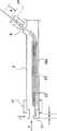
图2是本发明的实施方式的装配有护盖单元21且作为可动部件的护盖31不从护盖单元21突出的状态的内窥镜前端部2A的立体图。2 is a perspective view of the endoscope
图3是本发明的实施方式的护盖31从护盖单元21突出的状态的内窥镜前端部2A的立体图。3 is a perspective view of the endoscope
图4是示出本发明的实施方式的固定在开口部16上的状态的线固定部24的立体图。FIG. 4 is a perspective view showing the
图5是沿着图2的V-V线的穿过前端硬质部11的轴的剖面的剖面图。FIG. 5 is a cross-sectional view of a cross section passing through the axis of the distal end
图6是沿着图2的VI-VI线的穿过前端硬质部11的轴的剖面的剖面图。FIG. 6 is a cross-sectional view of a cross section passing through the axis of the distal
图7是本发明的实施方式的从护盖罩单元31A的前端侧观察的侧面图。FIG. 7 is a side view viewed from the front end side of the
图8是本发明的实施方式的护盖罩单元31A的正面图。FIG. 8 is a front view of a
图9是沿着图8的IX-IX线从箭头A4方向观察的剖面图。Fig. 9 is a cross-sectional view taken along line IX-IX of Fig. 8 as viewed from the direction of arrow A4.
图10是沿着图3的VII-VII线穿过内窥镜前端部2A的轴的剖面的剖面图。FIG. 10 is a cross-sectional view of a cross section passing through the axis of the endoscope
图11是本发明的实施方式的安装在开口部16上的状态的线固定部24的剖面图。FIG. 11 is a cross-sectional view of the
图12是用于说明本发明的实施方式的内窥镜辅助器械的作用的示意图。Fig. 12 is a schematic diagram for explaining the operation of the endoscope auxiliary instrument according to the embodiment of the present invention.
图13是本发明的实施方式的变形例1的在辅助器械贯穿插入口51a中设置有着色部的情况下的前端部2A的立体图。FIG. 13 is a perspective view of the
图14是沿着图13的XIV-XIV线的包含着色部94的区域的前端部2A的局部剖面图。FIG. 14 is a partial cross-sectional view of the
图15是本发明的实施方式的变形例2的开口部51a的周围发光的前端部2A的局部剖面图。15 is a partial cross-sectional view of a
图16是用于说明本发明的实施方式的变形例3的结构的图。FIG. 16 is a diagram illustrating the configuration of
具体实施方式Detailed ways
下面,参照附图对本发明的实施方式进行说明。Hereinafter, embodiments of the present invention will be described with reference to the drawings.
另外,在以下说明所使用的各图中,将各结构要素采用附图上能够识别的程度的大小,所以,比例尺按照各结构要素而不同,本发明不限于这些附图所记载的结构要素的数量、结构要素的形状、结构要素大小的比率和各结构要素的相对位置关系。In addition, in each of the drawings used in the following description, each component has a size that can be recognized on the drawing, so the scale is different for each component, and the present invention is not limited to the size of the components described in these drawings. The quantity, the shape of the structural elements, the ratio of the size of the structural elements and the relative positional relationship of each structural element.
首先,根据图1对本实施方式的内窥镜的结构进行说明。图1是示出本实施方式的内窥镜的结构的结构图。First, the configuration of an endoscope according to this embodiment will be described with reference to FIG. 1 . FIG. 1 is a configuration diagram showing the configuration of an endoscope according to the present embodiment.
内窥镜1构成为具有插入观察对象部位的细长的插入部2、在该插入部2的基端部连续设置的操作部3、从该操作部3的侧面延伸设置的通用缆线4。An endoscope 1 is configured to include an
细长的插入部2在其前端侧具有前端硬质部11,在该前端硬质部11的基端侧连续设置有作为弯曲自如的可动部的弯曲部12。进而,在该弯曲部12的基端侧连续设置有表面由软性的管状部件形成的长条状的具有挠性的挠性管部13。The
操作部3构成为具有构成操作把持部的操作部主体14、与插入部2的挠性管部13的基端侧连接的防折部15、配设在该防折部15的附近的插入部2内的辅助器械贯穿插入通道的开口部16。另外,虽然没有图示,但是,用于贯穿插入处置器械的处置器械贯穿插入口也设置在防折部15的附近。The
在操作部主体14上,以转动自如的方式配设有用于对插入部2的弯曲部12进行弯曲操作的多个弯曲操作旋钮17,并且,设有为了进行送气送水等而由用户操作的开关类18等。另外,弯曲操作旋钮17具有用于在上下方向上对弯曲部12进行弯曲操作的UD弯曲操作旋钮、用于在左右方向上对弯曲部12进行弯曲操作的RL弯曲操作旋钮,重叠配设这些弯曲操作旋钮。On the operation part
在插入部2的前端部能够装配护盖单元21。如后所述,在护盖单元21上连接有线缆22,线缆22从插入部21的前端部的辅助器械贯穿插入口插入,穿过辅助器械贯穿插入通道而从开口部16突出,通过固定线缆22的线固定部24进行固定。A
护盖单元21、线缆22和线固定部24构成内窥镜辅助器械。如后所述,在护盖单元21的前端侧设有作为可动部件的护盖31。The
图2是装配有护盖单元21且作为可动部件的护盖31不从护盖单元21突出的状态的内窥镜前端部2A的立体图。图3是护盖31从护盖单元21突出的状态的内窥镜前端部2A的立体图。2 is a perspective view of the endoscope
从图1的箭头A1所示的方向将圆筒状的护盖单元21装配在内窥镜前端部2A上。如图2所示,在护盖单元21的前端侧设有能够向前端方向突出的护盖31。护盖31是具有圆筒形状的部件即圆筒部件,如图3的箭头A3所示,构成为能够沿着内窥镜前端部2A的轴AX方向向内窥镜前端部2A的前端方向(前方)突出。The
线缆22由导管22a和贯穿插入其中的线23构成,该线缆22与护盖31连接。线23为不锈钢制,导管22a为特氟龙(注册商标)等树脂制。如后所述,通过向前端侧推出线23,护盖31沿着内窥镜前端部2A的轴AX方向向内窥镜前端部2A的前端方向(前方)突出,通过向基端侧拉入线23,护盖31沿着内窥镜前端部2A的轴AX方向向内窥镜前端部2A的基端方向(后方)拉入。由此,护盖31是能够沿着插入部2的轴方向突出没入的可动部件。The
线23的外周面由导管22a包覆,以使线23绝缘。The outer peripheral surface of the
在护盖单元21上固定有线缆22的一端。One end of the
穿过辅助器械贯穿插入通道内且从开口部16突出的线缆22的另一端由线固定部24固定。线固定部24从图1中箭头A2所示的方向固定在开口部16处。The other end of the
图4是示出固定在开口部16上的状态的线固定部24的立体图。线固定部24由2个操作部25、26和连接部27构成。操作部25是用于固定线缆22的操作部。操作部26是在使线缆22向前后方向运动时用于将其固定在期望位置的操作部件。连接部27具有用于将线固定部24装配在开口部16处并进行固定的机构。FIG. 4 is a perspective view showing the
如后所述,手术医生在通过连接部27将线固定部24装配在开口部16处并进行固定后,使线缆22穿过线固定部24的线贯穿插入通道。然后,手术医生通过操作部25固定线缆22,通过使线缆22向轴方向前后移动,使护盖31突出没入,该突出没入状态能够通过操作部26维持。As will be described later, after the operator fits and fixes the
(护盖单元的结构)(Structure of cover unit)
接着,对护盖单元21的结构进行说明。Next, the structure of the
图5是沿着图2的V-V线的穿过前端硬质部11的轴的剖面的剖面图。图6是沿着图2的VI-VI线的穿过前端硬质部11的轴的剖面的剖面图。FIG. 5 is a cross-sectional view of a cross section passing through the axis of the distal end
内窥镜插入部2的前端硬质部11包括在内部内置有摄像元件、物镜光学系统、照明部等的不锈钢制的硬质部件51。硬质部件51的基端部与弯曲部12的1个弯曲块52的内径部嵌合,包覆弯曲块52的软性的橡胶制的外皮部件53的前端部通过绕线部54固定在硬质部件51上。绕线部54是卷绕线并在该线上涂布粘接剂的区域。The distal end
在硬质部件51的前端面,与观察窗、照明窗、处置器械贯穿插入通道的开口部一起设有辅助器械贯穿插入通道的辅助器械贯穿插入口51a。这里,护盖单元21的线缆22从辅助器械贯穿插入口51a插入。护盖单元21以覆盖硬质部件51的方式装配在内窥镜插入部2的前端部2A。On the front end surface of the
在硬质部件51上形成有与处置器械贯穿插入口51a连接的孔51b,线缆22贯穿插入孔51b中。在孔51b的基端侧压入不锈钢制的管55,以覆盖管55的基端侧的外周的方式,连接有用于形成辅助器械贯穿插入通道56的通道导管57。树脂制的通道导管57通过粘接剂等固定在管55上。在通道导管57内贯穿插入线缆22。A
如图5和图6所示,护盖单元21由作为主体部的单元主体41、作为可动部件的圆筒状的护盖31、作为圆筒状的罩部件的护盖罩42构成。As shown in FIGS. 5 and 6 , the
单元主体41是前端侧部分的内径大于基端侧部分的内径的筒状部件,在前端侧部分与基端侧部分之间具有阶差部。单元主体41由人造橡胶等构成。在单元主体41的前端侧部分的筒状部的内侧插入护盖罩42并利用粘接剂进行固定。单元主体41构成为,内窥镜插入部2的前端部2A与单元主体41的基端侧部分的筒状部的内侧紧密贴合而嵌合安装。The unit
筒状的护盖罩42设置在单元主体41的前端侧部分的内径侧,在该护盖罩42的内径侧内插有作为可动部件的筒状的护盖31。护盖罩42是保持护盖31使其能够移动的保持部。进而,如后所述,护盖罩42是用于限制护盖31的运动的部件。A
护盖31以能够在内窥镜前端部2A的轴方向上突出没入的方式安装在护盖罩42上。护盖31和护盖罩42由聚碳酸酯等树脂构成。通过从护盖罩42的前端侧推入护盖31,能够使护盖31嵌入护盖罩42中。嵌入的护盖31能够沿着插入部2的轴方向移动。由此,护盖罩42构成保持部,其设置在内窥镜1的插入部2的前端部2A上,保持护盖31使其能够沿着插入部2的轴方向移动。The
在护盖单元21装配在插入部2的前端部2A上时,单元主体41的内周面与内窥镜前端部2A的外周面紧密贴合。在护盖单元21装配在插入部2的前端部2A上时,如图5所示,护盖单元21构成为,护盖罩42的前端部比硬质部件51的前端面向前方突出距离d1。即,作为保持部的护盖罩42具有比前端部2A的前端面向前端部2A的前端方向突出的突出部。由此,即使护盖31比硬质部件51靠前方,也通过护盖罩42的突出部来限制护盖31在与前端部2A的轴正交的方向上运动,防止护盖31突出没入时的晃动。When the
图7~图9是用于说明在护盖罩42中内插有护盖31并安装有线缆22的护盖罩单元31A的图。图7是从护盖罩单元31A的前端侧观察的侧面图。图8是护盖罩单元31A的正面图。图9是沿着图8的IX-IX线从箭头A4方向观察的剖面图。图10是护盖31从内窥镜前端部2A突出的状态下的沿着图3的VII-VII线穿过内窥镜前端部2A的轴的剖面的剖面图。7 to 9 are diagrams for explaining the
如图5所示,圆筒状的护盖31在前端侧具有内向凸缘部。进而,如图5和图7所示,护盖31在内向凸缘部的一部分具有向内径侧突出的突出部61。突出部61在护盖31的圆筒部的内侧具有用于固定线缆22的前端部的圆柱状的凸台62。在作为固定部的凸台62的基端部形成有供线缆22内的线23的前端部插入的孔62a。凸台62具有能够进入硬质部件51的孔51b内的尺寸。As shown in FIG. 5 , the
管63通过嵌入成形而设置在凸台62上,线23插入管63中并通过粘接剂进行固定。以覆盖管63的基端侧的外周部的方式装配有覆盖线23的导管22a。The
护盖31是圆筒部件,前端侧为圆筒部,但是,基端侧具有向基端方向延伸的多个延伸部,在各延伸部上设有爪部31a。如图5和图8所示,设有多个爪部31a,使得在护盖31内插在护盖罩42中时,该多个爪部31a沿着轴方向进入设于护盖罩42上的多个矩形的孔42a中。The
如图9所示,这里,3个孔42a绕着护盖罩42的轴以120度的间隔设置。对应于3个孔42a,在护盖31上设有向外径方向突出的3个爪部31a。As shown in FIG. 9 , here, three
另外,在圆筒状的护盖罩42上还设有多个、这里为3个孔42b,以防止其从单元主体41上脱落。In addition, a plurality of, here, three
进而,护盖罩42在前端侧具有外向凸缘部42c,在基端侧具有内向凸缘部42d。Further, the
如图8所示,护盖罩42沿着其前端部的外周具有锥部TP,进而,护盖31沿着其前端部的外周具有曲线部R。在图8中,如单点划线DT所示,护盖单元21构成为,在护盖31后退到护盖罩42的基端侧时,在沿着护盖单元21的轴方向的剖面中,护盖罩42的锥部TP的倾斜线和护盖31的曲线部R的切线DT大致一致。由此,能够实现护盖31与体内的粘膜等的平滑的接触。As shown in FIG. 8 , the
如图10所示,在通过线缆22使护盖31以向前端方向突出的方式移动时,通过使爪部31a与孔42a的前端侧的内周壁42e抵接,护盖31的移动停止。As shown in FIG. 10 , when the
并且,在通过线缆22使护盖31以向基端方向后退的方式移动时,如图5、图6所示,通过使护盖31的基端面的一部分与护盖罩42的孔42a的基端侧的内周壁42f抵接,护盖31的移动停止。In addition, when the
即,作为保持部的护盖罩42具有限制护盖31沿着插入部2的轴方向运动的运动限制部。具体而言,护盖31具有多个爪部31a,通过使多个爪部31a与作为限制部的孔42a的内周壁抵接,限制护盖31沿着插入部2的轴方向运动。That is, the
另外,如图9所示,3个爪部31a中的1个爪部31a配置成,在从前端侧观察护盖罩单元31A时,该爪部31a位于穿过护盖罩单元31A的中心轴O和固定有线23的前端部的凸台62的中心轴Oc的线L1上。这是为了防止使护盖31从前端部突出时的晃动。In addition, as shown in FIG. 9 , one of the three
(线固定部的结构)(Structure of wire fixing part)
接着,对线固定部24的结构进行说明。Next, the configuration of the
图11是安装在开口部16处的状态的线固定部24的剖面图。线固定部24的连接部27装配在开口部16上并进行固定。在连接部27上连接有操作部26。在操作部26的与连接部27相反的一侧连接有操作部25。FIG. 11 is a cross-sectional view of the
操作部25、26和连接部27分别具有圆柱形状,并且在连接的操作部25、26和连接部27的轴中心形成有供线缆22贯穿插入的线贯穿插入通道28。线缆22从开口部16突出并贯穿插入该线贯穿插入通道28内。The
如图4和图11所示,操作部25具有由手术医生把持而以绕轴转动的方式被操作的圆筒状的手柄71。在手柄71的基端侧形成有把持部71a,该把持部71a在外周部具有凹凸,使得手术医生容易进行操作。As shown in FIG. 4 and FIG. 11 , the
在树脂制的手柄71的前端侧的内侧具有内径较大的开口部71b,在开口部71b内的里侧即基端侧设有不锈钢制的圆筒部件71c。圆筒部件71c在基端侧具有内向凸缘部71c1。在圆筒部件71c的内侧设有由硅橡胶等构成的弹性部件71d。在弹性部件71d的基端侧形成有内向凸缘部71d1。在开口部71b的前端侧的内周面设有螺丝部(未图示)。The resin handle 71 has an
操作部26构成为具有圆筒状的树脂制的主体部81、在该主体部81的圆筒部的内侧设置的不锈钢制的连结部件82、设置在主体部81的外周并在轴方向上滑动的树脂制的滑块部件83、以及设置在滑块部件83的外周并绕轴转动的手柄84。The
连结部件82在基端侧具备具有外向凸缘部的突出部82a,弹性部件71d的内向凸缘部71d1和突出部82a的外向凸缘部卡合。The
进而,在连结部件82的前端侧的外周面形成有螺丝部(未图示),手柄71的前端侧的螺丝部在螺合区域scr中螺合。Furthermore, a screw portion (not shown) is formed on the outer peripheral surface of the
当使手柄71在规定方向上绕轴转动时,通过螺合区域scr,连结部件82相对于圆筒部件71c向基端侧相对移动。当进一步转动手柄71时,弹性部件71d被内向凸缘部71c1和连结部件82压缩,弹性部件71d与线缆22紧密贴合并从外周按压线缆22,其结果,线缆22固定在手柄71上。当使手柄71在相反方向上转动时,由于弹性部件71d不会被内向凸缘部71c1和连结部件82压缩,所以,线缆22不会被弹性部件71d按压,因此,其结果,线缆22成为未固定在手柄71上的状态。When the
并且,连结部件82经由在主体部81上形成的切口81a,通过固定部件81b与滑块部件83连接。因此,当连结部件82在轴方向上移动时,滑块部件83也一起向相同方向移动。进而,由于连结部件82连结滑块部件83和弹性部件71d,所以,当手柄71在轴方向上移动时,滑块部件83也向相同方向移动,固定在手柄部件71上的线缆22也向相同方向移动。Furthermore, the connecting
滑块部件83具有圆筒状的圆筒部83a和从圆筒部83a向前端方向延伸的多个延伸部83b。在滑块部件83的多个延伸部83b的外周面的一部分设有螺丝部(未图示),在手柄84的内周面设有与延伸部83b的螺丝部对应地螺合的螺丝部(未图示)。The
并且,在延伸部83b的外周面形成有锥部83c。在手柄84的内周面上,在与延伸部83b的锥部83c抵接的位置设有向内径方向突出的环状的突起部84a。Furthermore, a tapered
通过延伸部83b的螺丝部与手柄84的螺丝部的螺合,当使手柄84绕轴转动时,手柄84相对于滑块部件83在轴方向上相对移动。当手柄84在轴方向上移动时,手柄84的突起部84a按压延伸部83b的锥部83a,或者突起部84a与锥部83a分开。When the screw portion of the
由此,当手术医生使手柄在规定方向上绕轴转动时,手柄84相对于滑块部件83向基端侧方向相对移动,突起部84a按压锥部83a,能够将滑块部件83固定在主体部81上。并且,当手术医生使手柄在上述规定方向的相反方向上绕轴转动时,手柄84相对于滑块部件83向前端侧方向相对移动,突起部84a与锥部83a分开,滑块部件83能够相对于主体部81在轴方向上移动。Thus, when the operator rotates the handle in a predetermined direction, the
主体部81的前端侧经由用于与连接部27连接的固定部81b,固定在连接部27的连接部主体27a的基端部。在连接部主体27a的前端部27b的内侧设有橡胶制部件,前端部27b以能够装卸的方式与开口部16的金属制的接头16a连接。线缆22从连接部27的前端部27b的开口部27c插入。The front end side of the
(作用)(effect)
以上这种结构的内窥镜辅助器械的作用如下所述。手术医生从内窥镜前端部2A的辅助器械贯穿插入口51a插入与构成内窥镜辅助器械的护盖单元21连接的线缆22的基端部,使其穿过辅助器械贯穿插入通道56而从开口部16突出。The effect of the endoscope auxiliary instrument having the above structure is as follows. The surgeon inserts the proximal end of the
手术医生通过连接部27将线固定部24装配在开口部16上并进行固定后,从线固定部24的前端侧的开口部27b插入线缆22的基端部,使其贯穿插入操作部25、26和连接部27内的线贯穿插入通道28,并从操作部25的基端部的开口突出。After the operator fits and fixes the
在牵引线缆22而使护盖31没入即后退的状态下,使手柄71绕轴转动,将线缆22固定在手柄71上。此时,使手柄84也绕轴转动,将线缆22固定在线固定部24上。In a state where the
在使用护盖31时,使手柄84在相反方向上绕轴转动,成为未将线缆22固定在线固定部24上的状态,推压手柄71而向前端方向推出线缆22。其结果,与线缆22的前端连接的护盖31从内窥镜前端部2A突出。When using the
图12是用于说明内窥镜辅助器械的作用的示意图。将线缆22的基端部固定在线固定部24上,在手术医生利用护盖31时,使手柄84在轴方向上转动,解除滑块部件83相对于主体部81的固定状态,使手柄71向前端侧移动,将线缆22在开口部16内推入规定量,再次使手柄84在规定方向上转动,将滑块部件83固定在主体部81上。Fig. 12 is a schematic diagram for explaining the function of the endoscope auxiliary instrument. Fix the base end portion of the
由于线缆22被向前端侧推入规定量,所以,与线缆22的前端部连接的护盖31从前端部2A突出。Since the
由于护盖31的突出量d0被护盖罩42限制,所以不会成为规定量以上。如上所述,由于护盖31的爪部31a与护盖罩42的孔部42a的前端侧的内壁抵接,所以,护盖31不会进一步向前突出。Since the protrusion amount d0 of the
另一方面,线缆22的推入量di被设定为比护盖31的突出量d0大,使得即使内窥镜1的弯曲部12和插入部2的形状变化,也能够确保护盖31的突出量d0,并且,使得线缆22能够产生弹性力。On the other hand, the push-in amount di of the
当以推入量di推入线缆22时,如图12所示,线缆22成为在通道导管57内挠曲的状态。例如,如果设插入部2的长度为2m、护盖31的突出量do为3mm,则线固定部24中的线缆22的推入量di为10mm以上。When the
在这种状态下,在利用线固定部24固定线缆22的基端部的情况下,当护盖31在体腔内与粘膜等接触时,如图12中虚线所示,线缆22在通道导管57内挠曲,由于线缆22自身的弹性力而使护盖31向基端侧后退。In this state, when the base end portion of the
如图12所示,在护盖31突出的状态下,线缆22固定在线固定部24上,但是,线缆22处于在通道导管57内弯曲但被支撑的状态,换言之,处于从基端侧被按压的状态。在该状态下,当从前端侧对护盖31施加外力F时,根据所施加的外力,护盖31向基端方向后退即退避。但是,如果该外力F不施加给护盖31,则护盖31回归到作为初始位置的突出状态的位置。即,由于线缆22自身所具有的弹性力,相对于护盖31接触体腔壁时的反作用力,护盖31以具有弹性力的方式后退,所以,不会对体腔壁造成强烈冲击。As shown in FIG. 12, in the state where the
如上所述,线缆22的前端部与护盖31连接。而且,线缆22是使护盖31与护盖31的圆筒轴平行地且沿着插入部2的轴方向在前端部2A突出没入的部件,并且,线缆22具有挠性,构成回归力产生部件,在护盖承受朝向基端方向的外力时,产生使护盖31回归到突出状态的回归力。线固定部24构成固定该线缆22的基端部的固定部。另外,相对于来自护盖31的径方向的外力f,护盖31能够维持突出状态,所以,能够维持作为按压体腔内的褶皱并且正面观察切线方向的病变部时的护盖的功能。As described above, the front end portion of the
因此,根据以上的实施方式,能够实现如下的内窥镜辅助器械和内窥镜:不会使内窥镜的插入部的前端部的外径变粗,能够缓和护盖接触活体组织时的冲击。Therefore, according to the above embodiments, it is possible to realize an endoscope auxiliary instrument and an endoscope that can alleviate the impact when the cover comes into contact with living tissue without increasing the outer diameter of the distal end portion of the insertion portion of the endoscope. .
接着,对变形例进行说明。Next, modified examples will be described.
(变形例1)(Modification 1)
在从内窥镜前端部2A的辅助器械贯穿插入通道的辅助器械贯穿插入口51a插入线缆22时,为了区分辅助器械贯穿插入口51a和处置器械贯穿插入通道的开口部用的开口部,也可以在开口部51a中设置着色部。When inserting the
图13是在辅助器械贯穿插入口51a中设置着色部的情况下的前端部2A的立体图。在硬质部件51上,除了观察窗91、照明窗92和处置器械贯穿插入通道的开口部93以外,还存在有辅助器械贯穿插入通道的辅助器械贯穿插入口51a。在辅助器械贯穿插入口51a的稍微基端侧配置有以与周围部件不同的颜色例如蓝、黄、红等被着色的着色部94,使得手术医生不会误将线缆22插入处置器械贯穿插入通道的开口部93中。着色部94配置在手术医生观察前端部2A时能够视觉辨认的位置。FIG. 13 is a perspective view of the
图14是沿着图13的XIV-XIV线的包含着色部94的区域的前端部2A的局部剖面图。硬质部件51具有罩部件51c,在该罩部件51c的基端侧,在辅助器械贯穿插入口51a的周围安装有着色部94。因此,在罩部件51c的基端侧,在开口部51a的周围形成阶差部51d,通过在该阶差部51d内嵌入着色部94,能够将着色部94设置在硬质部件51上。FIG. 14 is a partial cross-sectional view of the
这样,通过设置着色部94,能够防止手术医生误将线缆22插入处置器械贯穿插入通道的开口部93中。In this way, by providing the
另外,在图13和图14的情况下,在罩部件51c上设置阶差部51d,将着色部94嵌入该阶差部51d中,但是,也可以不设置阶差部51d,如图14中单点划线所示,通过嵌入成形或注塑成形将着色部94设置在罩部件51c上。In addition, in the case of FIG. 13 and FIG. 14, a
另外,在上述例子中,将着色部94设置在辅助器械贯穿插入通道的辅助器械贯穿插入口51a中,但是,也可以将着色部94设置在处置器械贯穿插入通道的开口部93中,而不设置在辅助器械贯穿插入通道的辅助器械贯穿插入口51a中。这样,由于手术医生也能够区分2个开口部,所以,能够防止误将线缆22插入处置器械贯穿插入通道的开口部93中。In addition, in the above example, the
(变形例2)(Modification 2)
与变形例1同样,为了防止手术医生误将线缆22插入处置器械贯穿插入通道的开口部93中,也可以使辅助器械贯穿插入通道的辅助器械贯穿插入口51a发光。Similar to Modification 1, in order to prevent the surgeon from accidentally inserting the
图15是开口部51a的周围发光的前端部2A的局部剖面图。图15是与图13大致相同的位置的剖面图。Fig. 15 is a partial cross-sectional view of the
在辅助器械贯穿插入口51a的周围设有透明的树脂的环状部件95,在环状部件95的外周侧的一部分以紧密贴合的方式设有发光二极管(LED)元件(以下称为LED)96。当经由布线97对LED 96供给电流时,LED 96发光,光穿过环状部件95内而从前端侧射出。A transparent
由此,根据这种结构,也能够防止手术医生误将线缆22插入处置器械贯穿插入通道的开口部93中。Therefore, according to such a configuration, it is also possible to prevent the surgeon from inserting the
另外,如果不使用LED,例如如图15中单点划线所示,将来自未图示的光源装置的光导98的前端配置在环状部件95的附近、将来自光导98的光导入环状部件95内,则光从环状部件95射出,所以,能够防止手术医生误将线缆22插入处置器械贯穿插入通道的开口部93中。In addition, if LEDs are not used, for example, as shown by the single-dot chain line in FIG. Since light is emitted from the ring-shaped
进而,环状部件95使用包含具有蓄光性的荧光物质的材料也同样。Furthermore, the same applies to the use of a material containing a fluorescent substance having light-storage properties for the ring-shaped
(变形例3)(Modification 3)
与变形例1和2同样,为了防止手术医生误将线缆22插入处置器械贯穿插入通道的开口部93中,也可以在辅助器械贯穿插入通道内设置传感器,检测线缆22插入辅助器械贯穿插入口51a中的情况。Similar to
图16是用于说明变形例3的结构的图。如图16所示,在辅助器械贯穿插入口51a的附近设有传感器101,该传感器101检测线缆22插入辅助器械贯穿插入通道内的情况。传感器101的输出被供给到未图示的控制部(例如内窥镜装置的处理器),在从内窥镜前端部2A插入线缆22时,通过监视器中的显示、蜂鸣器的蜂鸣等,向手术医生告知传感器101检测到线缆22。FIG. 16 is a diagram for explaining the configuration of
传感器101例如是光耦合器、色彩传感器等。根据光耦合器,能够检测光被线缆22遮挡的情况。根据色彩传感器,能够检测线缆22的颜色。The
其结果,由于手术医生能够判断线缆22是否正确插入辅助器械贯穿插入口51a中,所以,能够防止误将线缆22插入处置器械贯穿插入通道的开口部93中。As a result, since the surgeon can determine whether the
另外,也可以将传感器102设置在开口部16的附近。In addition, the
(变形例4)(Modification 4)
在上述各例中,为了使内窥镜辅助器械的线缆22穿过,利用内窥镜辅助器械用的贯穿插入通道,但是,也可以不在内窥镜中设置内窥镜辅助器械用的贯穿插入通道,而利用内窥镜的处置器械贯穿插入通道。In each of the above-mentioned examples, in order to pass the
(变形例5)(Modification 5)
在上述各例中,用于使内窥镜辅助器械的线缆22穿过的内窥镜辅助器械用的贯穿插入通道设置在内窥镜插入部2内,但是,内窥镜辅助器械用的贯穿插入通道也可以设置在内窥镜插入部2的外侧。例如,可以在插入部2的外周设置用于使线缆22穿过的导管,利用该导管的管路作为内窥镜辅助器械用的贯穿插入通道。In each of the above-mentioned examples, the insertion channel for the endoscope auxiliary instrument through which the
(变形例6)(Modification 6)
在上述各例中,护盖31设置在装配于内窥镜插入部的前端部的单元主体41内,但是,也可以将护盖31设置在内窥镜插入部的前端部的前端硬质部11内。即,护盖31可以与前端硬质部11一体地构成。In each of the above examples, the
该情况下,将护盖罩42设置在前端硬质部11上、或者将具有与上述护盖罩42相同的功能的构造设置在前端硬质部11上。由此,存在不需要护盖单元的装配作业的优点。In this case, the
(变形例7)(Modification 7)
并且,也可以将护盖31设置在内窥镜插入部的前端硬质部11的外周。该情况下,在护盖31的内周和前端硬质部11的外周设置相互卡合的凸部和凹部,使得护盖31能够相对于前端硬质部11在长度轴方向上进退。由此,不需要护盖罩42,存在护盖装配时的前端外径的细径化和不需要护盖单元的装配作业的优点。In addition, the
如上所述,根据上述实施方式和各变形例,能够提供如下的内窥镜辅助器械和内窥镜:不会使内窥镜的前端部的外径变粗且不会使前端硬质部变长,能够缓和护盖接触活体组织时的冲击。As described above, according to the above-mentioned embodiment and each modified example, it is possible to provide an endoscope auxiliary instrument and an endoscope that do not increase the outer diameter of the distal end portion of the endoscope and that do not increase the rigidity of the distal end portion. Long enough to cushion the impact when the cover comes into contact with living tissue.
本发明不限于上述实施方式,能够在不改变本发明主旨的范围内进行各种变更、改变等。The present invention is not limited to the above-described embodiments, and various modifications, changes, and the like can be made within a range that does not change the gist of the present invention.
本申请以2011年8月9日在日本申请的日本特愿2011-174278号为优先权主张的基础进行申请,上述公开内容被引用到本申请说明书、权利要求书中。This application is filed on the basis of Japanese Patent Application No. 2011-174278 filed in Japan on August 9, 2011 as the basis for claiming priority, and the above disclosure is incorporated into the specification and claims of this application.
Claims (10)
Applications Claiming Priority (3)
| Application Number | Priority Date | Filing Date | Title |
|---|---|---|---|
| JP2011174278 | 2011-08-09 | ||
| JP2011-174278 | 2011-08-09 | ||
| PCT/JP2012/063796WO2013021710A1 (en) | 2011-08-09 | 2012-05-29 | Endoscope adapter and endoscope |
Publications (2)
| Publication Number | Publication Date |
|---|---|
| CN103458762Atrue CN103458762A (en) | 2013-12-18 |
| CN103458762B CN103458762B (en) | 2016-01-06 |
Family
ID=47668234
Family Applications (1)
| Application Number | Title | Priority Date | Filing Date |
|---|---|---|---|
| CN201280017253.9AActiveCN103458762B (en) | 2011-08-09 | 2012-05-29 | Endoscopic Auxiliary Instruments and Endoscopes |
Country Status (5)
| Country | Link |
|---|---|
| US (1) | US20130217963A1 (en) |
| EP (1) | EP2676595B1 (en) |
| JP (1) | JP5341278B2 (en) |
| CN (1) | CN103458762B (en) |
| WO (1) | WO2013021710A1 (en) |
Cited By (2)
| Publication number | Priority date | Publication date | Assignee | Title |
|---|---|---|---|---|
| CN105813539A (en)* | 2014-04-23 | 2016-07-27 | 奥林巴斯株式会社 | Retaining mechanism for endoscope guide member, and endoscope |
| WO2018082196A1 (en)* | 2016-11-03 | 2018-05-11 | 沈阳尚贤微创医疗器械股份有限公司 | Endoscope sleeve cylinder |
Families Citing this family (7)
| Publication number | Priority date | Publication date | Assignee | Title |
|---|---|---|---|---|
| JP6081424B2 (en)* | 2014-09-16 | 2017-02-15 | 富士フイルム株式会社 | Ultrasound endoscope hood and ultrasound endoscope |
| US10238272B2 (en) | 2014-09-29 | 2019-03-26 | Cook Medical Technologies Llc | Endoscope mountable visualization device quick-connect/release handle attachment mechanism |
| WO2016061291A1 (en) | 2014-10-18 | 2016-04-21 | Stryker European Holdings I, Llc | Surgical tool with a selectively bendable shaft and cables that selectively bend the shaft and that, when the shaft is bent, are in tension |
| WO2020183578A1 (en)* | 2019-03-11 | 2020-09-17 | オリンパス株式会社 | Endoscope |
| US20240252199A1 (en)* | 2021-03-24 | 2024-08-01 | Simpson Interventions, Inc. | Chronic total occlusion treatment system using low refractive index materials |
| CN118203286A (en)* | 2022-12-15 | 2024-06-18 | 浙江逸镜医疗器械有限公司 | Endoscope structure |
| CN119401311B (en)* | 2025-01-02 | 2025-03-14 | 湖南省华芯医疗器械有限公司 | Wire harness support, cable fixing structure and endoscope |
Citations (7)
| Publication number | Priority date | Publication date | Assignee | Title |
|---|---|---|---|---|
| CN1132469A (en)* | 1993-08-30 | 1996-10-02 | Stm医疗技术施塔恩贝格有限公司 | Endoscope with a movable frontal end area |
| US5569268A (en)* | 1994-04-26 | 1996-10-29 | Kabushiki Kaisha Top | Endoscopic instrument for ligating varix |
| US6095970A (en)* | 1997-02-19 | 2000-08-01 | Asahi Kogaku Kogyo Kabushiki Kaisha | Endoscope |
| JP2002301011A (en)* | 2002-03-22 | 2002-10-15 | Olympus Optical Co Ltd | Endoscope device and hood for endoscope |
| JP2003290134A (en)* | 2002-04-02 | 2003-10-14 | Olympus Optical Co Ltd | Endoscope device |
| CN1939207A (en)* | 2005-09-30 | 2007-04-04 | 奥林巴斯医疗株式会社 | Endoscope insertion aid and endoscope instrument |
| JP2010012172A (en)* | 2008-07-07 | 2010-01-21 | Hoya Corp | Endoscope distal end length adjustment system, endoscope hood |
Family Cites Families (11)
| Publication number | Priority date | Publication date | Assignee | Title |
|---|---|---|---|---|
| JPS5910964Y2 (en) | 1978-07-12 | 1984-04-05 | オリンパス光学工業株式会社 | Endoscope |
| JPH1033467A (en)* | 1996-07-25 | 1998-02-10 | Olympus Optical Co Ltd | Endoscope |
| JP4172845B2 (en)* | 1998-06-01 | 2008-10-29 | Hoya株式会社 | Zoom endoscope |
| JP2003093325A (en)* | 2001-09-25 | 2003-04-02 | Olympus Optical Co Ltd | Hood member for endoscope |
| JP2003093329A (en)* | 2002-04-08 | 2003-04-02 | Olympus Optical Co Ltd | Endoscope |
| JP4533695B2 (en)* | 2003-09-23 | 2010-09-01 | オリンパス株式会社 | Treatment endoscope |
| JP4768365B2 (en)* | 2005-08-31 | 2011-09-07 | 富士フイルム株式会社 | Insertion aid for endoscope and endoscope apparatus |
| JP4731256B2 (en)* | 2005-09-15 | 2011-07-20 | Hoya株式会社 | Endoscope treatment tool fixing mechanism |
| JP2008017938A (en)* | 2006-07-11 | 2008-01-31 | Olympus Medical Systems Corp | Endoscope, tip mounting member, and endoscope apparatus having these |
| US8905920B2 (en)* | 2007-09-27 | 2014-12-09 | Covidien Lp | Bronchoscope adapter and method |
| JP5489418B2 (en)* | 2008-05-08 | 2014-05-14 | オリンパスメディカルシステムズ株式会社 | Ultrasonic probe hood and ultrasonic probe |
- 2012
- 2012-05-29WOPCT/JP2012/063796patent/WO2013021710A1/enactiveApplication Filing
- 2012-05-29EPEP12821426.9Apatent/EP2676595B1/ennot_activeNot-in-force
- 2012-05-29JPJP2013502732Apatent/JP5341278B2/enactiveActive
- 2012-05-29CNCN201280017253.9Apatent/CN103458762B/enactiveActive
- 2013
- 2013-02-11USUS13/763,751patent/US20130217963A1/ennot_activeAbandoned
Patent Citations (7)
| Publication number | Priority date | Publication date | Assignee | Title |
|---|---|---|---|---|
| CN1132469A (en)* | 1993-08-30 | 1996-10-02 | Stm医疗技术施塔恩贝格有限公司 | Endoscope with a movable frontal end area |
| US5569268A (en)* | 1994-04-26 | 1996-10-29 | Kabushiki Kaisha Top | Endoscopic instrument for ligating varix |
| US6095970A (en)* | 1997-02-19 | 2000-08-01 | Asahi Kogaku Kogyo Kabushiki Kaisha | Endoscope |
| JP2002301011A (en)* | 2002-03-22 | 2002-10-15 | Olympus Optical Co Ltd | Endoscope device and hood for endoscope |
| JP2003290134A (en)* | 2002-04-02 | 2003-10-14 | Olympus Optical Co Ltd | Endoscope device |
| CN1939207A (en)* | 2005-09-30 | 2007-04-04 | 奥林巴斯医疗株式会社 | Endoscope insertion aid and endoscope instrument |
| JP2010012172A (en)* | 2008-07-07 | 2010-01-21 | Hoya Corp | Endoscope distal end length adjustment system, endoscope hood |
Cited By (4)
| Publication number | Priority date | Publication date | Assignee | Title |
|---|---|---|---|---|
| CN105813539A (en)* | 2014-04-23 | 2016-07-27 | 奥林巴斯株式会社 | Retaining mechanism for endoscope guide member, and endoscope |
| US9770158B2 (en) | 2014-04-23 | 2017-09-26 | Olympus Corporation | Holding mechanism for endoscope guide member, and endoscope |
| CN105813539B (en)* | 2014-04-23 | 2018-05-25 | 奥林巴斯株式会社 | For the holding mechanism and endoscope of endoscope-use guide member |
| WO2018082196A1 (en)* | 2016-11-03 | 2018-05-11 | 沈阳尚贤微创医疗器械股份有限公司 | Endoscope sleeve cylinder |
Also Published As
| Publication number | Publication date |
|---|---|
| CN103458762B (en) | 2016-01-06 |
| EP2676595B1 (en) | 2017-05-03 |
| EP2676595A4 (en) | 2014-03-12 |
| JP5341278B2 (en) | 2013-11-13 |
| JPWO2013021710A1 (en) | 2015-03-05 |
| WO2013021710A1 (en) | 2013-02-14 |
| US20130217963A1 (en) | 2013-08-22 |
| EP2676595A1 (en) | 2013-12-25 |
Similar Documents
| Publication | Publication Date | Title |
|---|---|---|
| CN103458762B (en) | Endoscopic Auxiliary Instruments and Endoscopes | |
| JP5139597B2 (en) | Endoscope | |
| JP5117263B2 (en) | Endoscope system | |
| US8333691B2 (en) | Endoscope comprising a flexible probe | |
| WO2018131204A1 (en) | Endoscope | |
| JP5959766B2 (en) | Endoscope | |
| JP5325416B2 (en) | Endoscope body and endoscope | |
| US20040064015A1 (en) | Endoscope treatment-device and measuring method | |
| JP5836505B2 (en) | Endoscopy adapter and endoscope | |
| WO2016002835A1 (en) | Medical puncture device | |
| JP6796215B2 (en) | Endoscope tip and endoscope | |
| WO2005063112A1 (en) | Endoscope | |
| JP6854978B2 (en) | Endoscope | |
| JP5942062B1 (en) | Endoscope | |
| US20180249899A1 (en) | Treatment instrument insertion tool | |
| JP4624718B2 (en) | Medical device insertion assistance device and medical device insertion system | |
| CN115381378A (en) | Front end cover dismounting clamp and endoscope | |
| JP6329712B1 (en) | Endoscope | |
| JP5687534B2 (en) | Operation handle device for in-vivo diagnostic device | |
| JP4242793B2 (en) | Ultrasonic treatment device | |
| JP2005230083A (en) | Endoscope | |
| JP6084849B2 (en) | Endoscopic surgery trocar and endoscopic surgery system using trocar | |
| JP2009183546A (en) | Separable endoscope | |
| JP2009183547A (en) | Separable endoscope | |
| JP2005312829A (en) | Illumination device for endoscope and endoscope using same |
Legal Events
| Date | Code | Title | Description |
|---|---|---|---|
| C06 | Publication | ||
| PB01 | Publication | ||
| C10 | Entry into substantive examination | ||
| SE01 | Entry into force of request for substantive examination | ||
| C41 | Transfer of patent application or patent right or utility model | ||
| TA01 | Transfer of patent application right | Effective date of registration:20151111 Address after:Tokyo, Japan, Japan Applicant after:Olympus Corporation Address before:Tokyo, Japan, Japan Applicant before:Olympus Medical Systems Corp. | |
| C14 | Grant of patent or utility model | ||
| GR01 | Patent grant |