CN103458180A - Communication terminal, display method, and computer program product - Google Patents
Communication terminal, display method, and computer program productDownload PDFInfo
- Publication number
- CN103458180A CN103458180ACN2013102101638ACN201310210163ACN103458180ACN 103458180 ACN103458180 ACN 103458180ACN 2013102101638 ACN2013102101638 ACN 2013102101638ACN 201310210163 ACN201310210163 ACN 201310210163ACN 103458180 ACN103458180 ACN 103458180A
- Authority
- CN
- China
- Prior art keywords
- image
- predetermined range
- information
- display
- unit
- Prior art date
- Legal status (The legal status is an assumption and is not a legal conclusion. Google has not performed a legal analysis and makes no representation as to the accuracy of the status listed.)
- Granted
Links
Images


Classifications
- G—PHYSICS
- G06—COMPUTING OR CALCULATING; COUNTING
- G06F—ELECTRIC DIGITAL DATA PROCESSING
- G06F16/00—Information retrieval; Database structures therefor; File system structures therefor
- G06F16/50—Information retrieval; Database structures therefor; File system structures therefor of still image data
- G06F16/54—Browsing; Visualisation therefor
- H—ELECTRICITY
- H04—ELECTRIC COMMUNICATION TECHNIQUE
- H04N—PICTORIAL COMMUNICATION, e.g. TELEVISION
- H04N23/00—Cameras or camera modules comprising electronic image sensors; Control thereof
- H04N23/60—Control of cameras or camera modules
- H04N23/698—Control of cameras or camera modules for achieving an enlarged field of view, e.g. panoramic image capture
- G—PHYSICS
- G06—COMPUTING OR CALCULATING; COUNTING
- G06F—ELECTRIC DIGITAL DATA PROCESSING
- G06F3/00—Input arrangements for transferring data to be processed into a form capable of being handled by the computer; Output arrangements for transferring data from processing unit to output unit, e.g. interface arrangements
- G06F3/01—Input arrangements or combined input and output arrangements for interaction between user and computer
- G06F3/048—Interaction techniques based on graphical user interfaces [GUI]
- G06F3/0481—Interaction techniques based on graphical user interfaces [GUI] based on specific properties of the displayed interaction object or a metaphor-based environment, e.g. interaction with desktop elements like windows or icons, or assisted by a cursor's changing behaviour or appearance
- G06F3/04817—Interaction techniques based on graphical user interfaces [GUI] based on specific properties of the displayed interaction object or a metaphor-based environment, e.g. interaction with desktop elements like windows or icons, or assisted by a cursor's changing behaviour or appearance using icons
Landscapes
- Engineering & Computer Science (AREA)
- Theoretical Computer Science (AREA)
- General Engineering & Computer Science (AREA)
- Physics & Mathematics (AREA)
- General Physics & Mathematics (AREA)
- Databases & Information Systems (AREA)
- Data Mining & Analysis (AREA)
- Human Computer Interaction (AREA)
- Signal Processing (AREA)
- Multimedia (AREA)
- User Interface Of Digital Computer (AREA)
- Studio Devices (AREA)
- Processing Or Creating Images (AREA)
- Two-Way Televisions, Distribution Of Moving Picture Or The Like (AREA)
- Telephone Function (AREA)
- Information Retrieval, Db Structures And Fs Structures Therefor (AREA)
- Television Signal Processing For Recording (AREA)
Abstract
Description
Translated fromChinese相关申请的交叉引用Cross References to Related Applications
本申请要求于2012年5月31日在日本提交的日本专利申请NO.2012-124567以及于2013年3月15日在日本提交的日本专利申请NO.2013-053565的优先权,并且将其全部内容通过参考进行合并。This application claims the benefit of Japanese Patent Application No. 2012-124567 filed in Japan on May 31, 2012 and Japanese Patent Application No. 2013-053565 filed in Japan on March 15, 2013, and all of them The content is incorporated by reference.
技术领域technical field
本发明涉及以全景图像显示预定范围图像的发明。The present invention relates to an invention for displaying an image of a predetermined range as a panoramic image.
背景技术Background technique
在最近的几年中,这种场合增加了:互联网用户将用数码相机等所拍摄的图像等上上传至互联网上的服务器计算机而另一用户下载该图像,从而,多个用户共享相同的图像。一些数码相机可以拍摄全球面全景图像,该全球面全景图像也被上传或者与其他用户共享(参考日本专利申请特开NO.2011-076249)。In recent years, such occasions have increased that an Internet user uploads an image etc. taken with a digital camera etc. to a server computer on the Internet and another user downloads the image, whereby a plurality of users share the same image . Some digital cameras can take a full-scale panoramic image, which is also uploaded or shared with other users (refer to Japanese Patent Application Laid-Open No. 2011-076249).
当通过用户将图像下载并且按照其原样显示在显示器上时,对于用户来说全景图像(例如,全球面全景图像)看起来是弯曲的。因此,用户将预定范围的图像显示在显示器上并且浏览图像,该预定范围的图像是全球面全景图像的一部分。When the image is downloaded by the user and displayed on the display as it is, the panoramic image (for example, a spherical panoramic image) appears curved to the user. Therefore, the user displays an image of a predetermined range, which is a part of the spherical panoramic image, on the display and browses the image.
因此,在显示器上所显示的图像是全景图像的一部分。随着下载了更多的全景图像,用户会发现更难找出哪个全景图像是正在被浏览的或者正在被浏览的图像属于哪个全景图像中的哪个预定范围。结果是,发生这样的问题:用户不能够轻易地找到想要的全景图像或者全景图像中的想要的预定范围的图像。发明内容Therefore, the image displayed on the display is part of a panoramic image. As more panoramic images are downloaded, the user will find it more difficult to find out which panoramic image is being browsed or which predetermined range in which panoramic image the image being browsed belongs to. As a result, there occurs a problem that the user cannot easily find a desired panoramic image or an image of a desired predetermined range in the panoramic image. Contents of the invention
本发明的目的是至少部分地解决传统技术中的问题。The purpose of the present invention is to at least partly solve the problems of the conventional technology.
根据本发明,提供了通信终端包括:存储单元,用于以相互对应的方式在其中存储预定范围信息和缩略图识别信息,所述预定范围信息用于指示全景图像中的预定范围,所述缩略图识别信息用于识别由所述预定范围信息指示的预定范围图像的缩略图;显示控制单元,用于控制预定显示单元以显示缩略图;以及接受单元,用于接受从所显示的缩略图中对预定缩略图的选择;其中基于所选择缩略图的缩略图识别信息,显示控制单元控制显示单元,以显示由对应于缩略图识别信息的预定范围信息所指示的预定范围图像。According to the present invention, there is provided a communication terminal comprising: a storage unit for storing therein predetermined range information and thumbnail identification information in a manner corresponding to each other, the predetermined range information indicating a predetermined range in a panoramic image, the thumbnail thumbnail identification information for identifying a thumbnail of a predetermined range image indicated by the predetermined range information; a display control unit for controlling a predetermined display unit to display the thumbnail; and an accepting unit for accepting the image from the displayed thumbnail. A selection of a predetermined thumbnail; wherein based on thumbnail identification information of the selected thumbnail, the display control unit controls the display unit to display a predetermined range of images indicated by predetermined range information corresponding to the thumbnail identification information.
本发明还提供一种用于使用通信终端显示图像的显示方法,该通信终端包括:存储单元,以相互对应的方式在其中存储用于识别全景图像的图像识别信息、用于指定全景图像中的预定范围的预定范围信息,和与预定范围相关的相关信息,该显示方法包括,通过通信终端:接受预定相关信息的选择;基于在接受步骤中所接受的预定相关信息检索存储单元,以便提取对应于预定相关信息的图像识别信息和预定范围信息;并且控制预定显示单元,以在由所提取的图像识别信息所识别的全景图像中,显示在所提取的预定范围信息中所指定的预定范围图像的缩略图。The present invention also provides a display method for displaying an image using a communication terminal, the communication terminal including: a storage unit storing therein, in a mutually corresponding manner, image identification information for identifying a panorama image; The predetermined range information of the predetermined range, and related information related to the predetermined range, the display method includes, through the communication terminal: accepting selection of the predetermined related information; retrieving the storage unit based on the predetermined related information accepted in the accepting step, so as to extract the corresponding image identification information and predetermined range information based on the predetermined related information; and controlling the predetermined display unit to display the predetermined range image specified in the extracted predetermined range information in the panoramic image identified by the extracted image recognition information thumbnail of the .
在上面所提到的显示方法中,接受步骤包括接受从所显示缩略图中对预定缩略图的选择;并且控制步骤包括控制显示单元以显示由对应于所选择缩略图的预定范围信息所指示的预定范围图像。In the above-mentioned display method, the accepting step includes accepting selection of a predetermined thumbnail from among the displayed thumbnails; and the controlling step includes controlling the display unit to display the area indicated by the predetermined range information corresponding to the selected thumbnail. Predetermined range image.
本发明还提供一种计算机程序产品,包括非瞬态计算机可读介质,其包含使计算机执行根据上述显示方法的步骤的计算机程序。The present invention also provides a computer program product including a non-transitory computer-readable medium containing a computer program for causing a computer to execute the steps according to the above display method.
附图说明Description of drawings
图1是示出根据本发明第一实施例的图像共享系统的示意图;FIG. 1 is a schematic diagram showing an image sharing system according to a first embodiment of the present invention;
图2(a)是拍照设备的左侧视图;图2(b)是拍照设备的前视图;图2(c)是拍照设备的俯视图;Fig. 2 (a) is the left side view of photographing equipment; Fig. 2 (b) is the front view of photographing equipment; Fig. 2 (c) is the top view of photographing equipment;
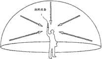
图3是示出拍照设备的使用状态的示意图;Fig. 3 is a schematic diagram showing the state of use of the photographing device;
图4(a)是示出由拍照设备所拍摄的半球面图像(前面)的示意图;图4(b)是示出由拍照设备所拍摄的半球面图像(后面)的示意图;图4(c)是示出由墨卡托投影所表示的图像的示意图;Fig. 4 (a) is a schematic diagram showing a hemispherical image (front) taken by a photographing device; Fig. 4 (b) is a schematic diagram showing a hemispherical image (back) taken by a photographing device; Fig. 4(c ) is a schematic diagram showing an image represented by a Mercator projection;
图5(a)是示出由墨卡托投影所表示的图像以及选择图像部分的示意图,并且图5(b)是示出选择图像的示意图;5( a ) is a schematic diagram showing an image represented by a Mercator projection and a selected image portion, and FIG. 5( b ) is a schematic diagram showing a selected image;
图6是示出全球面全景图像的示意图;Fig. 6 is a schematic diagram showing a spherical panoramic image;
图7是示出虚拟照相机以及预定范围的位置的示意图,假定全球面全景图像为三维球体;Fig. 7 is a schematic diagram showing the position of a virtual camera and a predetermined range, assuming that the global panoramic image is a three-dimensional sphere;
图8(a)是图7的三维透视图,并且图8(b)和图8(c)是示出通信终端在该通信终端的显示器上显示预定范围中的图像的示意图;FIG. 8(a) is a three-dimensional perspective view of FIG. 7, and FIG. 8(b) and FIG. 8(c) are schematic diagrams showing that the communication terminal displays images in a predetermined range on the display of the communication terminal;
图9是示出预定范围信息和预定范围图像之间的关系的示意图;FIG. 9 is a schematic diagram showing a relationship between predetermined range information and a predetermined range image;
图10是拍照设备的硬件配置示意图;Fig. 10 is a schematic diagram of the hardware configuration of the photographing device;
图11是通信终端的硬件配置示意图;FIG. 11 is a schematic diagram of a hardware configuration of a communication terminal;
图12是图像处理系统和图像管理系统的硬件配置示意图;Fig. 12 is a schematic diagram of the hardware configuration of the image processing system and the image management system;
图13是根据第一实施例的通信终端、图像处理系统以及图像管理系统的功能方框图;13 is a functional block diagram of a communication terminal, an image processing system, and an image management system according to the first embodiment;
图14是示出预定范围管理表格的概念示意图;FIG. 14 is a conceptual diagram showing a predetermined range management table;
图15是示出图像管理表格的概念示意图;FIG. 15 is a conceptual diagram showing an image management table;
图16是示出预定范围管理表格的概念示意图;FIG. 16 is a conceptual diagram showing a predetermined range management table;
图17是示出上传所拍摄图像的过程的时序图;FIG. 17 is a sequence diagram showing a process of uploading a captured image;
图18是示出下载所拍摄图像以及预定范围管理信息的过程的时序图;FIG. 18 is a sequence diagram showing a process of downloading captured images and predetermined range management information;
图19(a)是示出表示所共享的选择图像的所拍摄图像选择列表的示意图,并且图19(b)是示出预定范围图像的示意图;FIG. 19( a ) is a schematic diagram showing a captured image selection list representing shared selection images, and FIG. 19( b ) is a schematic diagram showing a predetermined range of images;
图20是示出通过用户设定和注册预定范围的过程的时序图;FIG. 20 is a sequence diagram illustrating a process of setting and registering a predetermined range by a user;
图21是示出预定范围的设定过程的流程图;FIG. 21 is a flowchart showing a setting process of a predetermined range;
图22是示出预定范围的设定过程的屏幕的例子;FIG. 22 is an example of a screen showing a setting process of a predetermined range;
图23(a)和图23(b)是示出预定范围的设定过程的屏幕的例子;23(a) and FIG. 23(b) are examples of screens showing the setting process of the predetermined range;
图24是显示多个关注点的示意图;Figure 24 is a schematic diagram showing multiple points of interest;
图25是示出缩小缩略图数目的过程的流程图;FIG. 25 is a flowchart illustrating a process of reducing the number of thumbnail images;
图26是示出相关信息类型选择按钮的示意图;Fig. 26 is a schematic diagram showing related information type selection buttons;
图27是示出创建日期选择菜单的示意图,该日期选择菜单是相关信息选择菜单的例子;FIG. 27 is a diagram showing a creation date selection menu, which is an example of a related information selection menu;
图28是示出缩略图的示意图;FIG. 28 is a schematic diagram showing thumbnail images;
图29(a)是示出创建者姓名选择菜单的示意图,该创建者姓名选择菜单是相关信息选择菜单的例子,图29(b)是示出场景选择菜单的示意图,该场景选择菜单是相关信息选择菜单的例子;Fig. 29(a) is a schematic diagram showing a creator name selection menu which is an example of a related information selection menu, and Fig. 29(b) is a schematic diagram showing a scene selection menu which is a related information selection menu. Example of information selection menu;
图30是示出显示预定范围图像的过程的流程图;30 is a flowchart showing a process of displaying a predetermined range image;
图31是示出具有预定视角的预定范围图像的示意图;Fig. 31 is a schematic diagram showing a predetermined range image with a predetermined viewing angle;
图32是示出在显示对应于缩略图的预定范围图像之前,显示预定范围图像的示意图;FIG. 32 is a diagram illustrating displaying a predetermined range image before displaying a predetermined range image corresponding to a thumbnail;
图33是示出在显示对应于缩略图的预定范围图像之前,显示预定范围图像的示意图;FIG. 33 is a diagram illustrating displaying a predetermined range image before displaying a predetermined range image corresponding to a thumbnail;
图34是示出对应于缩略图的预定范围图像的示意图;FIG. 34 is a diagram showing a predetermined range of images corresponding to thumbnails;
图35是根据第二实施例的通信终端的功能方框图;FIG. 35 is a functional block diagram of a communication terminal according to the second embodiment;
图36是示出第二实施例中,预定范围的设定过程的屏幕的例子;FIG. 36 is an example of a screen showing a setting process of a predetermined range in the second embodiment;
图37是根据第三实施例的图像管理系统7'的功能方框图;FIG. 37 is a functional block diagram of an image management system 7' according to the third embodiment;
图38是示出第三实施例中,下载所拍摄的图像以及预定范围管理信息的过程的时序图;以及FIG. 38 is a sequence diagram showing a procedure of downloading captured images and predetermined range management information in the third embodiment; and
图39是示出链路信息的描述的示意图。FIG. 39 is a diagram showing description of link information.
具体实施方式Detailed ways
以下将使用图1至图39描述本发明的实施例。An embodiment of the present invention will be described below using FIGS. 1 to 39 .
第一实施例first embodiment
以下将使用图1至图34描述本发明的第一实施例。A first embodiment of the present invention will be described below using FIGS. 1 to 34 .
实施例概要Example summary
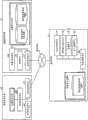
使用图1至图8,将首选描述本实施例的概要。图1是根据本发明的其中一个实施例的图像共享系统的示意图。Using FIG. 1 to FIG. 8 , the outline of the present embodiment will first be described. Fig. 1 is a schematic diagram of an image sharing system according to one embodiment of the present invention.
如图1所示的,用拍照设备1、多个通信终端3a、3b、3c和3d、图像处理系统5、和图像管理系统7来建立本实施例的图像共享系统。由用户A,B,C以及D分别使用通信终端3a,3b,3c以及3d。本实施例示出了用户A操作拍照设备1的情况。应注意的是,在以下的描述中,将3a,3b,3c以及3d中的任何一个表示为通信终端3。As shown in FIG. 1, the image sharing system of this embodiment is established with a photographing
拍照设备1是用于获取全球面全景图像的数码相机。通信终端3是计算机,例如,智能手机、平板计算机、笔记本计算机、台式计算机或者个人数字助理(PDA)。图像处理系统5以及图像管理系统7中的每一个是单服务器计算机或者由多个服务器计算机构成。The photographing
拍照设备1可以使用短距离无线技术(例如,近场通信(NFC)标准、或者蓝牙(注册商标)、无线保真(WiFi)或者TransferJet(注册商标)技术)与通信终端3进行通信。通信终端3可以经由通信网络9与图像处理系统5和图像管理系统7进行通信。通过移动通信系统(例如,第三代(3G)或者全球微波互联接入(WiMAX)系统),使用无线通信网络、使用基站9a,9b,9c以及9d以及用互联网来建立通信网络9。在拍照设备1与通信终端3之间、和/或在通信终端3与通信网络9之间可以使用有线通信。The photographing
接着,将使用图2描述拍照设备1的外观。在图2中,(a)是拍照设备的左侧视图;(b)是拍照设备的前视图;图2(C)是拍照设备的俯视图。Next, the appearance of the photographing
如图2(a)所示的,拍照设备1具有可以由人的一只手握住的尺寸。如图2(a)、2(b)以及2(c)所示的,在拍照设备1的顶部,在前表面(前侧)提供有图像采集设备103a,并且在后表面(后侧)提供有图像采集设备103b。如图2B所示的,在拍照设备1的前表面提供有包括快门按钮的操作单元115。As shown in FIG. 2( a ), the photographing
接着,以下将使用图3描述拍照设备1的使用状态。图3是示出拍照设备的使用状态的示意图。如图3所示的,用手握住拍照设备1,并且被用户用于拍摄周围的对象。在这种情况下,图2中所示的图像采集设备103a和103b捕捉用户周围的对象的图像,以便于能够获取两个各自半球面的图像。Next, the use state of the photographing
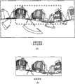
接着,将使用图4描述用拍照设备1所拍摄的图像和组合的图像。在图4中,(a)是示出由拍照设备所拍摄的半球面图像(前面)的示意图;(b)是示出由拍照设备所拍摄的半球面图像(后面)的示意图;以及(c)是示出由墨卡托(Mercator)投影(以下称为“墨卡托图像”)所表示的图像的示意图。Next, images captured with the photographing
如图4(a)所示的,由图像采集设备103a所获取的图像是通过稍后将被描述的广角透镜102a所拍摄的弯曲的半球面图像(前面)。如图4(b)所示的,由图像采集设备103b所获取的图像是通过稍后将被描述的广角透镜102b所拍摄的弯曲的半球面图像(后面)。拍照设备1将弯曲的半球面图像(前面)与被由此转换180度的半球面图像(后面)进行组合,以便于创建如图4(c)所示的墨卡托图像。As shown in FIG. 4( a ), an image acquired by the
接着,使用图5,将对墨卡托图像与用于选择墨卡托图像的选择图像之间的关系做出描述。在图5中,(a)是示出墨卡托图像以及选择图像部分的示意图,并且(b)是示出选择图像的示意图。如在此所示出的,由图5(a)的墨卡托图像中的虚线所限定的部分被用于创建图5(b)的选择图像。选择图像是从图1所示的拍照设备1发送至通信终端3a并且显示在通信终端3a上。接着,当用户A在通信终端3a上选择图5(b)中所示的选择图像时,将图4(c)所示的墨卡托图像的数据从拍照设备1发送至通信终端3a。以此,墨卡托图像被存储在通信终端3a中,并且,此外,经由图1所示的通信网络9被发送至图像管理系统7。此后,墨卡托图像经由通信网络9从图像管理系统7被发送至其他用户的通信终端3b、3c以及3d,并且被存储在通信终端3b、3c以及3d中。因此,墨卡托图像可以被共享。Next, using FIG. 5 , a description will be made on the relationship between the Mercator image and the selection image for selecting the Mercator image. In FIG. 5 , (a) is a schematic diagram showing a Mercator image and a selection image portion, and (b) is a schematic diagram showing a selection image. As shown here, the portion bounded by the dashed line in the Mercator image of FIG. 5( a ) is used to create the selection image of FIG. 5( b ). The selected image is sent from the photographing
接着,通信终端3b、3c以及3d使用用于嵌入式系统的开放式图像库(OpenGL ES)从图4(c)中所示的墨卡托图像创建图6中所示的全球面全景图像。图6是示出全球面全景图像的示意图。全球面全景图像可以是静止的图像或者是移动的图像。例如,通过使用OpenGL ES来创建例如图6所示的三维全球面全景图像,该OpenGL ES致使图5(a)所示的墨卡托图像被贴在虚拟三维球体的表面。可以创建仅仅二维全景图像来替代维全球面全景图像。同时,在此将墨卡托图像贴在虚拟三维球体的表面上,墨卡托图像可以例如被贴在立方体上,或者可以将二维全景图像贴在圆柱体上。Next, the
接着,将使用图7和图8对说明书的处理以及全球面全景图像中的预定范围T(以下称为“预定范围图像”)的图像显示做出说明。图7是示出虚拟照相机的位置以及预定范围的位置的示意图,将全球面全景图像假定为虚拟三维球体的表面。在图8中,(a)是图7的三维透视图,并且图(b)和(c)是示出通信终端在其显示器上显示预定范围图像的示意图。Next, the processing of the specification and image display of a predetermined range T (hereinafter referred to as “predetermined range image”) in a global panoramic image will be explained using FIGS. 7 and 8 . FIG. 7 is a schematic diagram showing the position of a virtual camera and the position of a predetermined range, assuming a spherical panorama image as the surface of a virtual three-dimensional sphere. In FIG. 8, (a) is a three-dimensional perspective view of FIG. 7, and drawings (b) and (c) are schematic diagrams showing that a communication terminal displays a predetermined range image on its display.
图7所示的虚拟照相机IC位于这样的虚拟用户的视点上:从作为全球面全景图像的三维球体CS的内部,观看显示在三维球体CS表面上的全球面全景图像。在图7中,虚拟照相机IC具体地位于三维球体的中心,并且可以通过中心关于三个轴进行旋转(摇摆、倾斜以及滚动(yaw,pitch and roll))。在全球面全景图像中的预定范围T是全球面全景图像中的虚拟照相机IC所拍摄的部分,并且由预定范围信息所指定。预定范围信息由坐标x(rH)、坐标y(rV)以及视角α(角)所表示。The virtual camera IC shown in FIG. 7 is located on the point of view of a virtual user viewing a spherical panorama image displayed on the surface of the three-dimensional sphere CS from the inside of the three-dimensional sphere CS as the spherical panorama image. In FIG. 7, the virtual camera IC is specifically located at the center of a three-dimensional sphere, and can be rotated about three axes (yaw, pitch and roll) through the center. The predetermined range T in the global panoramic image is a portion captured by the virtual camera IC in the global panoramic image, and is specified by the predetermined range information. The predetermined range information is represented by a coordinate x (rH), a coordinate y (rV), and a viewing angle α (angle).
在此,将使用图9详细描述预定范围信息。图9是示出预定范围信息和预定范围图像之间的关系的示意图。如图9所示,将由虚拟相机IC的视角α所表示的预定范围T的对角线视角记作2L,2L的中心点CP提供预定范围信息的(x,y)参数。从虚拟照相机IC到中心点CP的距离被记作f。接着,在图9中,通常满足由等式(1)所表达的三角函数等式。Here, the predetermined range information will be described in detail using FIG. 9 . FIG. 9 is a schematic diagram showing the relationship between predetermined range information and predetermined range images. As shown in FIG. 9 , the diagonal viewing angle of the predetermined range T represented by the viewing angle α of the virtual camera IC is denoted as 2L, and the center point CP of 2L provides (x, y) parameters of the predetermined range information. The distance from the virtual camera IC to the center point CP is denoted as f. Next, in FIG. 9 , the trigonometric function equation expressed by Equation (1) is generally satisfied.
L/f=tan(α/2) (1)L/f=tan(α/2) (1)
可以通过增宽或者缩小视角α的范围(弧)来完成预定范围T的缩放。如图8(b)所示,将图8(a)中所示的全球面全景图像中的预定范围T的图像作为预定范围图像显示在通信终端3d的显示器315上。在这种情况中的预定范围图像是表示全球面全景图像的一部分的部分图像P0。部分图像P0是基于预定范围信息的图像,该预定范围信息被最初设定(通过默认值)在图6中所示的全球面全景图像中。The scaling of the predetermined range T can be accomplished by widening or shrinking the range (arc) of the viewing angle α. As shown in FIG. 8(b), an image of a predetermined range T in the global panoramic image shown in FIG. 8(a) is displayed as a predetermined range image on the
如图8(b)所示,在预定范围图像(部分图像P0)中,显示了多个关注点AP1、AP2、AP3以及AP4,该多个关注点已经吸引了使用本实施例的图像共享系统的单个用户或者多个用户的注意,并且已经被他们设定。在预定范围T中,包括各自的关注点AP1、AP2、AP3以及AP4的确定范围中的图像,在显示器315的底部以缩略图T1、T2、T3以及T4的形式分别显示。例如,如果用户选择了缩略图T1,基于与缩略图T1相关的预定范围的信息,如图8(c)所示,显示器315显示在全球面全景图像中的预定范围图像(在此,部分图像P1)。应注意的是,图8(b)和图8(c)所示的缩略图是由通信终端3所创建的图像。As shown in FIG. 8(b), in the predetermined range image (partial image P0 ), multiple points of interest AP1, AP2, AP3, and AP4 are displayed, which have attracted image sharing using this embodiment. The attention of a single user or multiple users of the system and has been set by them. In the predetermined range T, the images in the determined range including the respective attention points AP1, AP2, AP3 and AP4 are displayed on the bottom of the
实施例的硬件配置The hardware configuration of the embodiment
接着,使用图10至图12,将对本实施例中的拍照设备、通信终端、图像处理系统以及图像管理系统的硬件配置做出详细描述。Next, using FIGS. 10 to 12 , a detailed description will be made of the hardware configurations of the photographing device, communication terminal, image processing system, and image management system in this embodiment.
使用图10,将首先描述拍照设备1的硬件配置。图10是拍照设备的硬件配置示意图。同时假定拍照设备1是使用下面描述的两个图像采集设备的全方向拍照设备,拍照设备1可以具有三个或者多个或者任意数目的图像采集设备,并且不需要专门用于全方向拍摄的设备。Using FIG. 10 , the hardware configuration of the photographing
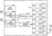
如图10所示的,拍照设备1由图像捕捉单元101、图像处理单元104、图像捕捉控制单元105、中央处理单元(CPU)111、只读存储器(ROM)112、静态随机访问存储器(SRAM)113、动态随机访问存储器(DRAM)114、操作单元115、网络I/F116、通信单元117以及天线117a组成。As shown in Figure 10, the
图像捕捉单元101装备有广角透镜(被称作鱼眼透镜)102a和102b,每个广角透镜具有180度或者更宽的视角以捕捉半球图像,以及对应于各自广角透镜的两个图像采集设备103a和103b。每个图像采集设备103a和103b包含例如互补金属氧化物半导体(CMOS)传感器或者电荷耦合元件(CCD)传感器的图像传感器,将由广角透镜形成的光学图像转换成电信号的图像数据并且输出图像数据;计时生成单元,生成例如水平或者垂直合成信号以及图像传感器的像素时钟信号的信号;以及注册组,其中设定了操作图像采集设备所需要的各种命令、参数等。The
图像捕捉单元101的图像采集设备103a和103b二者均经由并行I/F总线或者串行I/F总线连接至图像处理单元104。此外,图像捕捉单元101的图像采集设备103a和103b二者均经由串行I/F总线(例如I2C总线)连接至图像捕捉控制单元105。图像处理单元104和图像捕捉控制单元105经由总线110连接至CPU111。总线110也与ROM112、SRAM113、DRAM114、操作单元115以及网络I/F116等连接。Both the
图像处理单元104经由并行I/F总线获取从图像采集设备103a和103b输出的图像数据,并且在将预定的过程应用到图像数据之后,组合图像数据以创建例如图4(c)中所示的墨卡托图像的数据。The
图像捕捉控制单元105通常用作主设备并且图像采集设备103a和103b用作从设备,并且图像捕捉控制单元105使用I2C总线设定图像采集设备103a和103b的注册组中的命名等。根据需要从CPU111接收命令等。图像捕捉控制单元105也使用I2C总线以获取图像采集设备103a和103b的每个注册组的状态数据等,并且将所获取的数据发送至CPU111。The image
图像捕捉控制单元105命令图像采集设备103a和103b在按压了操作单元115的快门按钮时输出图像数据。一些拍照设备具有预览显示功能和/或使用显示器显示移动图像的功能。在那些功能中,连续地以预定帧率(每分钟的帧)从图像采集设备103a和103b输出图像数据。The image
如稍后将描述的,与CPU111协作的图像捕捉控制单元105还用作对来自图像采集设备103a和103b的图像数据的输出定时进行同步的同步控制单元。虽然不向本实施例中的拍照设备提供显示单元,但是可以提供显示单元。As will be described later, the image
CPU111控制整个拍照设备1的操作并且执行必要的处理。ROM112存储用于CPU111的各种计算机程序。SRAM113和DRAM114是工作存储器,存储由CPU111执行的程序、在处理过程中的数据等。对于这两个存储器,DRAM114存储当前正由图像处理单元104处理的图像数据以及在被处理之后的墨卡托数据。The
操作单元115是用于例诸如各种操作按钮、电源开关、快门按钮以及具有显示和操作输入功能二者的触摸板的设备的集合术语。用户操作操作按钮以便于进入各种拍摄模式和拍摄条件。The
网络I/F116是用于与例如外部介质,包括SD卡和USB存储器以及个人计算机的设备进行接口的接口电路(例如,USB I/F)的集合术语。网络I/F116也可以是无线网络接口或者有线网络接口。存储在DRAM114中的墨卡托图像的数据经由网络I/F116被记录到外部介质中,和/或,按照需要经由作为网络I/F的网络I/F116被发送至例如通信终端3的外部设备。The network I/
通信单元117使用例如无线保真(WiFi)或者蓝牙(注册商标)技术的短距离无线技术,经由天线117a与例如通信终端3的外部设备进行通信。通信单元117也可以将墨卡托图像的数据发送至通信终端3的外部设备。The
接着,将使用图11描述通信终端3的硬件配置。图11是作为通信终端的智能电话的硬件配置示意图。Next, the hardware configuration of
如图11所示,通信终端3装备有:CPU301,控制整个通信终端3的操作;ROM302,存储基本输入/输出程序;随机访问存储器(RAM)303,用作为CPU301的工作区域;电可擦除和可编程ROM(EEPROM)304,根据CPU301的控制读取和写入数据;作为图像采集设备的CMOS305,其在CPU301的控制下捕捉对象的图像以获取图像数据;各种加速/方向传感器306,包括检测地磁场的电磁罗盘或者旋转罗盘,以及加速传感器;以及介质驱动器308,其控制从/向例如闪存的介质307读取和写入(存储)数据。在介质驱动器308的控制下,读取已经记录在记录介质307中的数据,或者将数据新写入记录介质307中,其被配置是可移除的。As shown in FIG. 11, the
EEPROM304存储操作系统(OS)、其他的计算机程序以及由CPU301所执行的各种类型的数据。CCD用于替代CMOS305。The
通信终端3还装备有:声音输入单元311,将声音转换成音频信号;音频输出单元312,将音频信号转换成声音;天线313a;通信单元313,使用天线313a与用无线通信信号的附近基站9a进行通信;全球定位系统(GPS)接收单元314,从GPS卫星接收通信终端3的包括定位信息(纬度、经度以及高度)的GPS信号;液晶或者有机EL显示器315,显示对象的图像以及各种图标;安装在显示器315上的触摸板316,由压力传感或者静电板组成,并且检测由手指、触控笔等在显示器315上所触碰的触碰位置;以及总线310,包括地址总线以及数据总线,用于电连接上述单元。The
应注意的是,音频输入单元311包括用于接收声音的麦克风,并且音频输出单元312包括用于产生声音的扬声器。It should be noted that the
接着,将使用图12描述图像处理系统5和图像管理系统7的硬件配置。图12是图像处理系统5和图像管理系统7的硬件配置示意图。图像处理系统5和图像管理系统7二者都是通常的服务器计算机;因此,以下将仅描述图像处理系统5的配置,并且省略对图像管理系统7的配置的描述。Next, the hardware configurations of the
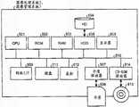
图像处理系统5装备有:CPU501,控制整个图像处理系统5的操作;ROM502,存储用于驱动CPU501的例如IPL的计算机程序的,;RAM503,用作CPU501的工作区域的;HD504,存储用于图像处理系统5的例如计算机程序的各种类型的数据;硬盘驱动器(HDD)505,根据CPU501的控制,控制从/向HD504读取和写入各种类型的数据;介质驱动器507,控制从/向例如闪存的记录介质506读取或者写入(存储)数据;显示器508,显示例如光标、菜单、窗口、字符以及图像的各种类型信息;网络I/F509,用于使用通信网络9进行数据通信;键盘511被提供有多个按键,用于输入字符、数值、各种指令等;鼠标512,用于选择或者执行各种指令、选择将要处理的对象、移动光标等;压缩磁盘只读存储器(CD-ROM)驱动器514,控制从/向以CD-ROM513为例的可擦除记录介质读取和写入各种类型的数据;以及总线510,包括地址总线以及数据总线,用于电连接如图12所示的上述组成元件。The image processing system 5 is equipped with: a CPU 501 that controls the operation of the entire image processing system 5; a ROM 502 that stores a computer program such as IPL for driving the CPU 501; a RAM 503 that is used as a work area for the CPU 501; Various types of data such as computer programs of the processing system 5; hard disk drive (HDD) 505, which controls reading and writing of various types of data from/to HD 504 according to the control of CPU 501; media drive 507, which controls data from/to A recording medium 506 such as a flash memory reads or writes (stores) data; a display 508 displays various types of information such as cursors, menus, windows, characters, and images; a network I/F 509 is used for data communication using the communication network 9 The keyboard 511 is provided with a plurality of keys for inputting characters, numerical values, various instructions, etc.; the mouse 512 is used for selecting or executing various instructions, selecting objects to be processed, moving the cursor, etc.; compressed disk read-only memory ( CD-ROM) drive 514, which controls reading and writing various types of data from/to a removable recording medium such as CD-ROM 513; and a bus 510, including an address bus and a data bus, for electrically connecting such as The above-mentioned constituent elements shown in FIG. 12 .
实施例的功能配置Functional configuration of the embodiment
接着,以下将使用图13描述本实施例的功能配置。图13是本实施例的通信终端3、图像处理系统5以及图像管理系统7的功能方框图。在图13中,通信终端3、图像处理系统5以及图像管理系统7可以经由通信网络9通信数据。Next, the functional configuration of the present embodiment will be described below using FIG. 13 . FIG. 13 is a functional block diagram of the
通信终端的功能配置Function configuration of communication terminal
如图13中所示,通信终端3包括发送/接收单元31、操作输入接受单元32、创建单元33、显示控制单元34以及存储/提取单元39。这些单元中的每个是这样的功能或者方法:根据从ROM302或者EEPROM304所装载并且在被用在RAM303中的、用于通信终端3的程序,由来自CPU301的命令所驱动的,通过操作如图11所示的任何组成元件而实现的。As shown in FIG. 13 ,
通信终端3还包括由图11所示的ROM302、RAM303以及EEPROM304所组建的存储单元3000。在存储单元3000中,建立了由稍后将描述的预定范围管理表格所组成的预定范围管理数据库(DB)3001。存储单元3000在其中存储拍摄图像(墨卡托图像)、选择图像以及缩略图的数据。
预定范围管理表格Scheduled Scope Management Form
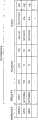
图14是示出预定范围管理表格的概念示意图。预定范围管理表格管理预定范围管理信息。预定范围管理信息以彼此对应的方式包括:用于识别缩略图的缩略图识别信息、用于识别全球面全景图像的图像识别信息、用于指定全球面全景图像中的预定范围的预定范围信息、以及与预定范围相关的多个相关类型的信息。FIG. 14 is a conceptual diagram showing a predetermined range management table. The predetermined range management table manages predetermined range management information. The predetermined range management information includes, in correspondence with each other, thumbnail identification information for identifying a thumbnail, image identification information for identifying a global panoramic image, predetermined range information for specifying a predetermined range in the global panoramic image, and a number of related types of information related to the predetermined range.
在这些类型的信息中,缩略图识别信息是例如用于识别缩略图的缩略图ID。如果文件名能够唯一地识别缩略图,那么缩略图识别信息可以是缩略图的文件名来代替缩略图ID。Among these types of information, the thumbnail identification information is, for example, a thumbnail ID for identifying a thumbnail. If the file name can uniquely identify the thumbnail, the thumbnail identification information may be the file name of the thumbnail instead of the thumbnail ID.
图像识别信息是例如用于识别全球面全景图像的图像ID。如果识别符能够唯一指定图像,那么图像识别信息可以是例如文件名的另一识别符来代替图像ID。The image identification information is, for example, an image ID for identifying a spherical panoramic image. If the identifier can uniquely specify the image, the image identification information may be another identifier such as a file name instead of the image ID.
相关信息包括,例如,当用户指定了全球面全景图像中的预定范围图像时,指示数据的“指定日期”、指示指定了预定范围图像的用户是谁的“指定用户的姓名”以及指示预定范围图像的场景的“场景”。作为另一个例子,除了全球面全景图像中的指定日期之外,相关信息还可以包括指定的时间、所拍摄图像的被拍摄位置以及其他信息。The related information includes, for example, when the user designates a predetermined range image in the global panoramic image, "designated date" indicating data, "designated user's name" indicating who the user designated the predetermined range image is, and indicating the predetermined range The "scene" of the scene of the image. As another example, in addition to the specified date in the global panorama image, the relevant information may also include specified time, the captured location of the captured image, and other information.
通信终端的功能配置Function configuration of communication terminal
接着,使用图11和图13,以下将更详细地描述通信终端3的功能配置。Next, using FIG. 11 and FIG. 13 , the functional configuration of
通信终端3的发送/接收单元31主要是通过由图11所示的通信单元313和CPU301的处理而实现的,并且经由通信网络9向/从图像处理系统5以及图像管理系统7发送并且接收各种类型的数据(或者信息)。The transmission/
操作输入接受单元32主要是通过由触摸板316和CPU301的处理而实现的,并且接受来自用户的选择的各种类型以及输入。The operation input accepting unit 32 is mainly realized by processing by the
创建单元33主要是通过CPU301的处理而实现的。基于由存储/提取单元39提取的、由图像识别信息识别的全球面全景图像中的预定范围图像(由存储/提取单元39提取的预定范围信息中所指定的预定范围图像),创建单元33为预定范围图像创建缩略图,并且还创建用于识别所创建的缩略图的缩略图识别信息。创建单元33还将缩略图与缩略图识别信息进行关联。The
此外,基于由预定范围管理DB3001所管理的预定范围管理信息的相关信息的类型,创建单元33创建稍后将描述的相关信息选择菜单。例如,在创建指示指定用户姓名的相关信息选择菜单的情况下,创建单元33从相关信息中提取指定用户姓名,并且创建指示指定用户姓名的相关信息选择菜单,例如稍后将描述的图29A所示出的。Furthermore, based on the type of related information of the predetermined range management information managed by the predetermined
显示控制单元34主要是通过CPU301的处理而实现的,并且控制显示器315显示各种图像、字符等。例如,在由用户所选择的并且由操作输入接受单元32所接受的、对应于预定相关信息的图像识别信息所识别的全球面全景图像中,显示控制单元34控制显示器315显示用于预定范围图像的缩略图,该预定范围图像是由对应于所选择的以及所接受的预定相关信息所指定的。The
显示控制单元34还控制显示器315,显示对应于在操作输入接受单元32所选择的缩略图的预定范围图像。The
稍后将描述的,如图27中所示出的,显示控制单元34进一步控制显示器315,在显示器315上显示的预定范围图像上,显示相关信息选择菜单(指定日期选择菜单)3141,其用于选择预定范围图像的指定日期。在这种情况下,存储/提取单元39读取预先存储在存储单元3000中的指定日期选择菜单的日期,以便于显示控制单元34能够控制显示器315以显示指定日期选择菜单。As will be described later, as shown in FIG. 27 , the
存储/提取单元39将各种类型的数据(或者信息)存储在存储单元3000中,并且从存储单元3000中提取各种类型的数据。存储/提取单元39将数据(例如,所拍摄的图像(墨卡托图像)、选择图像以及缩略图)记录到存储单元3000中并且从存储单元3000进行提取。例如,存储/提取单元39基于由操作输入接受单元32所接受的预定相关信息,检索预定范围管理DB3001,以便于提取对应于预定相关信息的图像识别信息和预定范围信息。在这种情况下,显示控制单元34控制显示器315,以将用于由存储/提取单元39提取的、由预定范围信息所指定的预定范围图像的缩略图显示在通过存储/提取单元39提取的、由图像识别信息指定的全球面全景图像中。The storage/
图像处理系统的功能配置Functional Configuration of Image Processing System
接着,以下将使用图13详细描述图像处理系统5的功能配置。图像处理系统5包括发送/接收单元51、场景设定单元52以及存储/提取单元59。这些单元中的每个是这样的功能或者方法:根据从HD504所装载的并且被用在RAM503中的、用于图像处理系统5的程序,由来自CPU501的命令所驱动的,通过操作如图12所示的任何组成元件而实现的。Next, the functional configuration of the
信息处理系统5还包括图12中所示的RAM503以及HD504所组建的存储单元5000。存储单元5000在其中存储各种类型的数据(或者信息)。The
图像处理系统的功能配置Functional Configuration of Image Processing System
接着,使用图12和图13,以下将详细描述图像处理系统5的功能配置。Next, using FIG. 12 and FIG. 13 , the functional configuration of the
图像处理系统5的发送/接收单元51主要是通过图12中所示的网络I/F509和CPU501的处理而实现的,并且经由通信网络9向/从通信终端3以及图像管理系统7发送并且接收各种类型的数据(或者信息)。The sending/receiving
基于例如全球面全景图像中的预定范围图像的颜色和亮度(lightness),场景设定单元52确定由预定范围图像表示人物、风景、建筑以及其他中的哪个场景,并且为预定范围图像设定最佳的场景。通过使用在数码相机中所使用的通用自动场景识别功能,基于全球面全景图像中的颜色信息和形状信息来执行设定场景的这种方法。Based on, for example, the color and lightness of a predetermined range image in a global panoramic image, the
存储/提取单元59将各种类型的数据(或者信息)存储在存储单元5000中,并且从存储单元5000中提取各种类型的数据(或者信息)。The storage/
图像管理系统的功能配置Function configuration of image management system
接着,将使用图12和图13详细描述图像管理系统7的功能配置。图像管理系统7包括发送/接收单元71、管理单元72以及存储/提取单元79。这些单元中的每个是这样的功能或者方法:根据从HD504所装载的并且在被用在RAM503中的、用于图像管理系统7的程序,由来自CPU501的命令所驱动的、通过操作如图12所示的任何组成元件的操作而实现的。Next, the functional configuration of the
图像管理系统7还包括由图12中所示的RAM503以及HD504所组建的存储单元7000。在存储单元7000中,建立了由稍后将描述的图像管理表格所组成的图像管理DB7001。在存储单元7000中,还建立了由稍后将描述的预定范围管理表格所组成的预定范围管理DB7002。The
图像管理表格Image Management Form
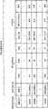
图15是示出图像管理表格的概念示意图。图像管理表格管理图像管理信息。图像管理信息以彼此对应的方式包括:用于识别全球面全景图像(所拍摄的图像)的图像识别信息,以及用作该全球面全景图像的元数据的附加信息等。Fig. 15 is a conceptual diagram showing an image management table. The image management table manages image management information. The image management information includes, in correspondence with each other, image identification information for identifying a global panoramic image (taken image), additional information serving as metadata of the global panoramic image, and the like.
在这些类型的信息中,图像识别信息是与图14中所示的图像识别信息相同的信息。附加信息包括:“公开信息”,其指示是否用户公开了本实施例的图像共享系统中的图像;“所拍摄图像数据大小(MB)”;“所拍摄图像的摄影日期/时间”以及“关注点的数目”。这里,在公开信息上的标记“O”指示公开了图像,而标记“X”指示未公开图像。关注点的数目指的是在如图8B所示的一个全球面全景图像中所设定的关注点的数目。作为另一个例子,除了所拍摄图像的摄影日期/时间之外,附加信息可以包括所拍摄图像被拍摄的位置以及其他信息。Among these types of information, the image identification information is the same information as the image identification information shown in FIG. 14 . The additional information includes: "public information" indicating whether or not the user has disclosed images in the image sharing system of this embodiment; "captured image data size (MB)"; number of points". Here, a mark "O" on the public information indicates that an image is disclosed, and a mark "X" indicates that an image is not disclosed. The number of points of interest refers to the number of points of interest set in a global panoramic image as shown in FIG. 8B . As another example, in addition to the shooting date/time of the captured image, the additional information may include the location where the captured image was captured and other information.
预定范围管理表格Scheduled Scope Management Form
图16是示出上预定范围管理表格的概念示意图。应注意的是,图16所示的预定范围管理表格被用于管理由用户上传的所拍摄的图像,而图14所示的预定范围管理表格被用于由用户单独地本地管理通信终端3上的所拍摄的图像。FIG. 16 is a conceptual diagram showing an upper predetermined range management table. It should be noted that the predetermined range management table shown in FIG. 16 is used to manage captured images uploaded by the user, while the predetermined range management table shown in FIG. 14 is used to locally manage images on the
图像管理系统的功能配置Function configuration of image management system
接着,将使用图13详细描述图像管理系统7的功能配置。Next, the functional configuration of the
图像管理系统7的发送/接收单元71主要是通过图12中所示的通信I/F509和CPU501的处理而实现的,并且经由通信网络9向/从通信终端3和图像处理系统5发送并且接收各种类型的数据(或者信息)。The sending/receiving
管理单元72将图像识别信息增加到从通信终端3发送的所拍摄图像的报头(header)中,以管理图像管理系统7中的所拍摄图像。The
存储/提取单元79将各种类型的数据(或者信息)存储在存储单元7000中,并且从存储单元7000中提取各种类型的数据(或者信息)。The storage/
实施例的处理和操作Example Processing and Operation
接着,将使用图17至图25描述本实施例的处理和操作。将首先使用图17描述上传所拍摄图像的过程。图17是示出上传所拍摄图像的过程的时序图。Next, the processing and operation of the present embodiment will be described using FIGS. 17 to 25 . The process of uploading captured images will be described first using FIG. 17 . FIG. 17 is a sequence diagram showing a process of uploading captured images.
如图17所示,拍照设备1将如图4(a)和图4(b)所示的两个半球图像进行组合以创建图4(c)所示的所拍摄图像(墨卡托图像),并且如图5所示,进一步从所拍摄图像创建选择图像(步骤S1)。As shown in FIG. 17 , the photographing
接着,通信终端3a从拍照设备1请求选择图像(步骤S2)。这致使拍照设备1将在步骤S1中所创建的、与相关的选择图像以及选择图像所基于的所拍摄图像的图像ID,发送给通信终端3a(步骤S3)。结果是,通信终端3a的发送/接收单元31接收选择图像以及图像ID。Next, the
接着,如图11所示的,通信终端3a的显示控制单元34控制显示器315,以显示选择图像,并且提示用户A选择选择图像(步骤S4)。作为回应,当用户A在显示器315的触摸板上选择了选择图像部分时,操作输入接受单元32接受该选择(步骤S5)。这致使发送/接收单元31从拍照设备1请求选择图像所基于的所拍摄图像(步骤S6)。在这种情况下,发送/接收单元31将上面步骤S3中发送的图像ID发回给拍照设备1,以便于指定所需要的拍摄图像。因此,拍照设备1接受对所拍摄图像的请求。Next, as shown in FIG. 11 , the
接着,拍照设备1将关于所拍摄图像的、上面步骤S6中所接受的被请求的所拍摄图像以及例如所拍摄图像的元数据的附加信息,发送给通信终端3a(步骤S7)。结果是,通信终端3a的发送/接收单元31接收所拍摄图像以及附加信息。Next, the photographing
接着,通信终端3a的显示控制单元34控制显示器315,以在其上显示所拍摄的图像(步骤S8)。这允许用户A确认将被上传至图像管理系统7的所拍摄图像。Next, the
接着,如果用户上传了所拍摄图像,那么通信终端3a的发送/接收单元31将所拍摄图像发送给图像管理系统7(步骤S9)。在此时,还与所拍摄图像一起发送所拍摄图像的附加信息。结果是,图像管理系统7的发送/接收单元71接收所拍摄的图像以及其附加信息。Next, if the user uploads the captured image, the transmission/
接着,为了管理图像管理系统7中的、在步骤S7接收的所拍摄图像,图像管理系统7的管理单元72将图像识别信息增加到所拍摄图像的报头中(步骤S10)。应注意的是,图像识别信息是这样的ID,其不同于在上面的步骤S3和S6所发送和接收的图像ID,并且其被增加用于独立地管理图像管理系统7中的所拍摄图像。Next, in order to manage the captured image received in step S7 in the
接着,存储/提取单元79,以如同图像管理信息一样的彼此对应的方式,将与上面步骤S9所接收的、被增加到所拍摄图像上的图像识别信息和附加信息相同的图像识别信息,存入图像管理DB7001中(步骤S11)。Next, the storage/
接着,管理单元72通过所拍摄图像创建共享的选择图像,并且将与以上步骤S10所增加的图像识别信息相同的图像识别信息,增加到共享选择图像的数据的报头中(步骤S12)。应注意的是,共享选择图像是在用户从图像管理系统7下载所需要的所拍摄图像之前,由用户所选择的图像,以指定将被下载的所拍摄图像。共享的选择图像在图19中示出,并且稍后将进一步地描述。例如,使用如同上面步骤S1和图5所说明的相同的方法,创建共享的选择图像。Next, the
接着,存储/提取单元79将上面步骤S10中图像识别信息被增加到的所拍摄图像和上面步骤S11中图像识别信息被增加到的共享选择图像存储在存储单元700中(步骤S13)。这意味着,通过相同的图像识别信息,在图像管理DB7001中所管理的图像管理信息,与存储单元7000中所管理的所拍摄图像和所共享选择图像相关联。Next, the storage/
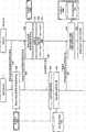
接着,使用图18,将对如下过程做出描述:在该过程中,通信终端3b下载所拍摄图像和预定范围管理信息。图18是示出下载所拍摄图像和预定范围管理信息的过程的时序图。Next, using FIG. 18, a description will be made of a procedure in which the
首先,通信终端3b的发送/接收单元31从图像管理系统7请求共享选择图像和图像管理信息(步骤S21)。这致使图像管理系统7的发送/接收单元71接受该请求。First, the transmission/
接着,图像管理系统7的存储/提取单元79从存储单元7000读取共享选择图像,并且从存储单元7000的图像管理DB7001读取图像管理信息。然后,发送/接收单元71将在上面步骤S22中读取的共享选择图像和图像管理信息,发送至请求源头的通信终端3b(步骤S23)。结果是,通信终端3b的发送/接收单元31接收共享选择图像和图像管理信息。然后,通信终端3b的存储/提取单元39将在上面步骤S23中所接收的共享选择图像和图像管理信息,存储在存储单元3000中(步骤S24)。Next, the storage/
接着,基于共享选择图像和图像管理信息,通信终端3b的创建单元33创建用于所拍摄图像的选择的共享图像选择列表(步骤S25)。接着,通信终端3b的显示控制单元34控制通信终端3b的显示器315,以如图19(a)所示的,显示该共享图像选择列表SL,以便于提示用户B选择共享选择图像CE(步骤S26)。应注意的是,如图19(a)所示,共享图像选择列表SL将共享的选择图像CE与附于其上的图像管理信息一起进行显示。例如,将商业区中的建筑显示为共享选择图像CE,并且将摄影日期/时间(2011/09、20,11:21)、所拍摄图像的大小(13.1MB)和关注点组的编号(0)显示为图像管理信息。Next, based on the shared selection image and the image management information, the
接着,当用户B选择所需要的共享选择图像CE时,通信终端3b的操作输入接受单元32接受选择(步骤S27)。接着,通信终端3b的发送/接收单元31,将增加到在上面步骤S27所选择的共享选择图像CE的图像识别信息,发送到图像管理系统7(步骤S28)。结果是,图像管理系统7的发送/接收单元71接收图像识别信息。Next, when the user B selects a desired shared selection image CE, the operation input accepting unit 32 of the
接着,图像管理系统7的存储/提取单元79从存储单元7000读取所拍摄图像,与上面所接收的图像识别信息相同的图像识别信息被增加到该所拍摄图像(步骤S29)。进一步地,存储/提取单元79从存储单元7000的预定范围管理DB7002读取预定范围管理信息,其包括与上面所接收的图像识别信息相同的图像识别信息(步骤S30)。在图像管理系统7中,基于由图像管理DB7001所管理的图像管理信息的附加信息中的“公开”属性,如果属性指示不公开(如果给出了标记“X”),则在上面的步骤S29之前,管理单元确定不需要执行上面的步骤S29和S30。Next, the storage/
接着,发送/接收单元71将上面步骤S29中所读取的所拍摄图像和上面步骤S30中所读取的预定范围管理信息,发送给通信终端3b(步骤S31)。结果是,通信终端3b的发送/接收单元31接收所拍摄图像和预定范围管理信息,并且因此终止对所拍摄图像的下载。应注意的是,在由通信终端3b所接收的所拍摄图像中还未设定关注点,以便于预定范围管理信息什么也不包括(是空的)。Next, the transmission/
然后,通信终端3b的存储/提取单元39将上面步骤S31中下载的所拍摄图像存储到存储单元3000中,并且还将上面步骤S31中下载的预定范围管理信息存储到存储单元1000的预定范围管理DB3001中(步骤S32)。Then, the storage/
然后,通信终端3b的创建单元33基于所拍摄图像创建如图6中所示的全球面全景图像,并且显示控制单元34控制通信终端3b的显示器35来显示全球面全景图像(步骤S33)。Then,
在此,当用户B使用触摸板316操作通信终端3b以扩大在显示器315上显示的全球面全景图像时,操作输入接受单元32接受用户B的操作,以致使显示控制单元34扩大并且将全球面全景图像的一部分显示为如同例如图19(b)所示的平面预定范围图像。Here, when user B operates
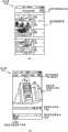
在图19(b)中,显示器315显示了预定范围图像显示区域3110、缩略图显示区域3120以及相关信息选择区域3130的宽泛分开的区域。预定范围图像显示区域3110是显示全球面全景图像或者例如图19(b)所示的平面预定范围图像的区域。缩略图显示区域3120是显示用于平面预定范围图像的缩略图的区域,该平面预定范围图像包括由用户设定的关注点。相关信息选择区域3130是由用户使用的、用于选择以缩小缩略图类型,并且显示稍后将描述的相关信息选择按钮的区域。相关信息选择区域3130显示相关信息类型显示按钮3130F用于显示相关信息选择按钮。当用户选择了相关信息类型显示按钮3130F时,显示出稍后将描述的各种相关信息选择按钮。In FIG. 19( b ), the
接着,使用图20,将对这种情况做出描述:其中,用户B设定包括关注点的预定范围并且在图像管理系统7中注册该预定范围。图20是示出通过用户设定和注册预定范围的过程的时序图。Next, using FIG. 20 , a description will be made of a case where the user B sets a predetermined range including a point of interest and registers the predetermined range in the
通信终端3b执行包括关注点的预定范围的设定过程(步骤S41)。在此,使用图21以及图22,将更详细地描述步骤S41。图21是示出预定范围的设定过程的流程图。图22是示出预定范围的设定过程的屏幕示例。The
首先,如图22所示,当用户B按压并且保持关注点AP1时,AP1是在预定范围图像(部分图像P)中吸引用户B的注意的位置,操作输入接受单元32接受关注点AP1(步骤S41-1)。First, as shown in FIG. 22 , when the user B presses and holds the attention point AP1, which is a position that attracts the attention of the user B in a predetermined range image (partial image P), the operation input accepting unit 32 accepts the attention point AP1 (step S41-1).
接着,如图22所示,显示控制单元34显示器35显示以已经被按压并且被保持的关注点AP1为中心的选择框3113(步骤S41-2)。应注意的是,显示选择框3113的周界被掩饰,以便与显示选择框3113进行区别。Next, as shown in FIG. 22 , the
然后,当用户B调整了显示选择框3113时,操作输入接受单元32接受对选择框的调整(步骤S41-3)。选择框3113的这个调整改变了图7所示的虚拟照相机的坐标和视角。Then, when the user B adjusts the
然后,当用户B按压预定范围确定按钮3111时,在上面步骤S41-3中进行调整之后,操作输入接受单元32接受范围的设定,作为关注区域(步骤S41-4)。这致使存储/提取单元39将在上面步骤S41-4所接受的关注范围上的预定范围管理信息,存储在预定范围管理DB3001中(步骤S41-5)。该通信终端使用预定范围管理信息,来指定将要管理的所拍摄图像的预定范围并且生成缩略图。该通信终端还生成对应于所生成的缩略图的缩略图识别信息,并且以如同对应于预定范围管理信息一样的方式,将缩略图和缩略图识别信息存储在预定范围管理DB3001中。Then, when the user B presses the predetermined
此时,将除了场景之外的图像识别信息、预定范围信息以及相关信息,存储在例如14中所示的预定范围管理信息的类型中。具体地,图像识别信息是通信终端3中管理的所拍摄图像的图像ID。预定范围信息是在上面步骤S41-4中设定的虚拟照相机的坐标和视角。相关信息是指定预定范围图像的日期/时间,预定范围图像是通过上面步骤S41-4中设定包括关注点的预定范围而指定的;以及上面步骤S41-4中所设定的用户B(指定预定范围者)的姓名,并且不包括关注范围的场景。显示/不显示关注点切换按钮3112是用于在关注点的显示和不显示之间进行切换的按钮,稍后将描述。At this time, image identification information other than the scene, predetermined range information, and related information are stored in the type of predetermined range management information shown in 14, for example. Specifically, the image identification information is an image ID of a captured image managed in the
接着,参考回图20,通信终端3的发送/接收单元31,将在上面步骤S41-5中所存储的预定范围管理信息和缩略图识别信息,发送至图像处理系统5(步骤S42)。结果是,图像处理系统5的发送/接收单元51接收预定范围管理信息和缩略图识别信息。Next, referring back to FIG. 20 , the transmission/
然后,图像处理系统5将上面步骤S42中所接收的预定范围管理信息中的图像识别信息,发送给图像管理系统7,以便于请求对应于图像识别信息的所拍摄图像(步骤S43)。结果是,图像管理系统7的发送/接收单元71接收图像识别信息并且接收对对应于图像识别信息的所拍摄图像的请求。Then, the
然后,图像管理系统7中的存储/提取单元79从存储单元7000读取在上面步骤S43中所接收的图像识别信息被增加到的所拍摄图像(步骤S44)。然后,发送/接收单元71将上面步骤S44中所读取的所拍摄图像发送给图像处理系统5(步骤S45)。结果是,图像处理系统5的发送/接收单元51接收所拍摄图像。Then, the storage/
然后,基于在上面步骤S42所接收的预定范围管理信息的预定范围信息,以及上面步骤S45所接收的所拍摄图像,图像处理系统5中的场景设定单元52设定在上面步骤S41-4中所设定的预定范围的场景(步骤S46)。具体地,基于所拍摄图像和预定范围信息,并且基于所拍摄图像中的预定范围图像的例如颜色以及亮度的信息,场景设定单元52确定人物、风景、建筑以及其他中的哪个场景由预定范围所表示,并且为预定范围图像设定最佳场景。应注意的是,当通信终端3b和3c接着访问图像管理系统7并且执行从步骤S21至S31的过程以接收预定范围管理信息时,通信终端3b和3c从图像管理系统7接收已经设定场景的信息。Then, based on the predetermined range information of the predetermined range management information received in the above step S42, and the captured image received in the above step S45, the
然后,图像处理系统5的发送/接收单元51,将包括上面步骤S46中所确定的场景的预定范围管理信息,发送至图像管理系统7(步骤S47)。结果是,图像管理系统7的发送/接收单元71接收预定范围管理信息和缩略图识别信息。Then, the sending/receiving
然后,图像管理系统7的存储/提取单元79将上面步骤S47所接收的预定范围管理信息和缩略图识别信息,存储到预定范围管理DB7002中,以便于增加预定范围管理信息和缩略图识别信息的新条目(pieces)(步骤S48)。Then, the storage/
接着,使用图23,将对这种情况做出描述:在图1中所示的用户B设定关注范围之后,如图18所示,用户C从图像管理系统7下载所拍摄图像、预定范围管理信息以及缩略图识别信息。在图23中,(a)和(b)是示出预定范围的设定过程的屏幕示例,并且对应于图19B示出用于用户B的屏幕,(a)示出了用于用户C的屏幕,并且对应于图22示出用于用户B的屏幕,(b)示出了用于用户C的屏幕。Next, using FIG. 23 , a description will be made of the case where, after user B shown in FIG. 1 sets the attention range, as shown in FIG. management information and thumbnail identification information. In FIG. 23, (a) and (b) are screen examples showing the setting process of a predetermined range, and a screen for user B is shown corresponding to FIG. 19B, and (a) is a screen for user C screen, and corresponding to FIG. 22 shows the screen for user B, (b) shows the screen for user C.
在图23(a)中,由用户B设定的关注点AP1被显示在预定范围图像中的特定位置中(部分图像P)。用于包括由用户B设定的关注点AP1的预定范围图像的缩略图T1,被显示在缩略图显示区域3120中。在缩略图T1中的右上角上,显示了由已经浏览该预定范围图像的、本实施的图像共享系统的用户所输入的注释的编号。In FIG. 23( a ), the attention point AP1 set by the user B is displayed in a specific position (partial image P) in the predetermined range image. Thumbnails T1 for predetermined range images including the attention point AP1 set by the user B are displayed in the
缩略图是由用户C的通信终端3c的创建单元33所创建的图像。创建单元33基于上面步骤S31中由用户C下载的所拍摄图像和预定范围管理信息,创建缩略图。具体地,基于与所下载的所拍摄图像一起被接收的预定范围管理信息中的预定范围信息,如图7中所示的,基于所拍摄图像,创建单元33确定全球面全景图像中的虚拟照相机IC的坐标和视角,并且在这种情形下,减少预定范围T中的预定范围图像的大小。因此,创建单元33创建缩略图。然后将所创建的缩略图与已接收的缩略图识别信息进行关联。The thumbnail image is an image created by the
然后,当用户C想要增加新的关注点时,用户C指定图23(b)中所示的关注点AP2,并且将关注点AP2的参数设定为预定范围,以便于执行与图20和21所示的相同的过程。Then, when the user C wants to add a new point of interest, the user C specifies the point of interest AP2 shown in FIG. 21 shows the same process.
如上所述,使用图像共享系统的各种用户设定关注范围,以便于用户够知道吸引其他用户关注的地方。这带来了这样的效果:用户能够迅速地浏览吸引其他用户关注的地方。As described above, various users who use the image sharing system set attention ranges so that the users are able to know places that attract the attention of other users. This has the effect that users can quickly browse places that attract the attention of other users.
然而,设定多个关注点(预定范围)可以迷惑打算浏览预定范围图像的用户迷惑。因此,使用图24至图34,以下将对在图1所示的用户D使用通信终端3d将多个缩略图缩小到想要的缩略图的过程做出描述。图24是显示多个关注点的示意图。图25是示出缩小缩略图的数目的过程流程图;However, setting a plurality of points of interest (predetermined range) can confuse users who intend to browse images of the predetermined range. Therefore, using FIG. 24 to FIG. 34, a description will be made below of a process in which the user D shown in FIG. 1 reduces a plurality of thumbnail images to a desired thumbnail image using the
首先,以与用户B和用户C相同的方式,基于在步骤S31中所下载的所拍摄图像和预定范围管理信息,用户D将例如图24所示的预定范围图像显示在通信终端3d的显示器315上。关注点AP1、AP2、AP3、AP4等被显示在预定范围图像中。在这种状态下,在缩略图区域2130中不显示缩略图。First, in the same manner as user B and user C, user D displays, for example, a predetermined range image as shown in FIG. superior. The points of interest AP1, AP2, AP3, AP4, etc. are displayed in the predetermined range image. In this state, no thumbnails are displayed in the thumbnail area 2130 .
在此,假定用户D按压了图24中的相关信息类型显示按钮(筛选按钮)3130F,以将关注点(预定范围图像)缩小到预定范围图像的想要的类型。然后,如图25所示,操作输入接受单元32接受按压(步骤S101)。如图26所示,这致使显示控制单元34控制显示器315,来显示相关信息选择区域3130中的相关信息类型选择按钮(这里的日期按钮)3131、相关信息类型选择按钮(这里的用户按钮)3132以及相关信息类型选择按钮(这里的场景按钮)3133(步骤S102)。图26是示出相关信息类型选择按钮的示意图。Here, assume that the user D has pressed the related information type display button (filter button) 3130F in FIG. 24 to narrow down the focus (predetermined range image) to a desired type of predetermined range image. Then, as shown in FIG. 25 , the operation input accepting unit 32 accepts a press (step S101 ). As shown in FIG. 26 , this causes the
接着,当用户D按压了上面提到的三个按钮3131、3132和3133中的任何一个时,操作输入接受单元32接受三个按钮3131、3132和3133之一的选择(步骤S103)。操作输入接受单元32还确定是否相关信息类型选择按钮(日期按钮)3131被接受(步骤S104)。Next, when the user D presses any one of the above-mentioned three
如果步骤S104确定相关信息类型选择按钮(日期按钮)3131被按压为“是”,那么,存储/提取单元39读取预先存储在存储单元3000中的指定日期选择菜单的数据(步骤S105)。然后,如27所示,显示控制单元34控制显示器315以将相关信息选择菜单(这里的指定日期选择菜单)3141显示在预定图像上(步骤S106)。图27是示出表示预定范围图像的指定日期的指定日期选择菜单的示意图,这是相关信息选择菜单的例子。If step S104 determines that the relevant information type selection button (date button) 3131 is pressed as "Yes", then the storage/
接着,当用户D按压想要的日期时,操作输入接受单元32接受对预定范围图像被指定的日期的选择(步骤S107)。然后,存储/提取单元39将步骤S107中所接受的日期的信息用作检索关键词来检索预定范围管理DB3001,以提取包括相关信息的预定范围管理信息,该相关信息的指定日期的值与被接受的日期相同,并且以此缩小预定范围管理信息(步骤S108)。Next, when the user D presses a desired date, the operation input accepting unit 32 accepts selection of a date on which a predetermined range image is designated (step S107 ). Then, the storage/
然后,使用上面步骤S108中所提取的预定范围管理信息的预定范围信息,创建单元33应用图7和图8A所示的方法,来为所拍摄图像指定预定范围图像,该所拍摄图像是由上面步骤S108中所提取的预定范围管理信息的图像识别信息所指示的,并且通过预定范围图像创建缩略图(步骤S109)。创建单元33还为预定范围管理信息的所有条目创建缩略图,该预定范围管理信息包括相关信息,其指定日期的值与上面步骤S107所接受的日期相同。此时,用于所创建缩略图的识别,创建单元33将所创建缩略图与已经被接收的缩略图识别信息进行关联。Then, using the predetermined range information of the predetermined range management information extracted in step S108 above, the creating
然后,如图28所示,显示控制单元34控制显示器315,以在缩略图显示区域3120中显示由创建单元33创建的所有缩略图,并且以此更新缩略图显示区域3120的显示(步骤S110)。图28是示出缩略图的示意图。Then, as shown in FIG. 28, the
如果步骤S104未确定相关类型选择按钮(日期按钮)3131被按压为“不”,那么,存储/提取单元39从预定范围管理DB3001读取这样的相关信息,该相关信息表示与从相关信息类型选择按钮(用户按钮)3132和相关信息类型选择按钮(场景按钮)3133中所选出的案件相关的名称(步骤S111)。例如,如果上面的步骤S103接受相关信息类型选择按钮(用户按钮)3132,那么读取指定用户的姓名的属性(字段)中的所有姓名。如果上面的步骤S103接受相关信息类型选择按钮(场景按钮)3133,那么读取场景的属性(字段)中的所有名称。If it is not determined in step S104 that the related type selection button (date button) 3131 is pressed as "No", then the storage/
接着,基于上面步骤S111所读取的名称,创建单元33创建相关信息选择菜单(步骤S112)。例如,如图29(a)所示,如果上面步骤S103已经选择了相关信息类型选择按钮(用户按钮)3132,那么创建单元33创建表示指定了预定范围图像的指定用户的姓名的相关信息选择菜单(指定用户的姓名选择菜单)3142。如图29(b)所示,如果上面步骤S103已经选择了相关信息类型选择按钮(场景按钮)3133,那么创建单元33创建表示指定预定范围图像的场景的相关信息选择菜单(场景选择菜单)3143。Next, based on the name read in step S111 above, the
图29(a)是示出表示指定预定范围图像的用户姓名的指定用户姓名选择菜单的示意图,并且是相关信息选择菜单的例子。图29(b)是示出表示预定范围图像的场景的场景选择菜单的示意图,并且是相关信息选择菜单的例子。FIG. 29( a ) is a diagram showing a designation user name selection menu representing a user name designating a predetermined range image, and is an example of a related information selection menu. Fig. 29(b) is a schematic diagram showing a scene selection menu representing a scene of a predetermined range image, and is an example of a related information selection menu.
接着,显示控制单元34控制显示器315以显示上面步骤S112所创建的相关信息选择菜单(步骤S113)。其后,执行与上面步骤S107相同的过程,因此将省略对其的描述。Next, the
接着,使用图30和34,将描述显示预定范围图像的过程。图30是示出显示预定范围图像的过程的流程图。图34是示出对应于缩略图的预定范围图像的示意图。Next, using FIGS. 30 and 34, a process of displaying a predetermined range image will be described. Fig. 30 is a flowchart showing a process of displaying a predetermined range image. Fig. 34 is a diagram showing predetermined range images corresponding to thumbnail images.
首先,假定用户D按压上面步骤S110中显示的多个缩略图中想要的缩略图。然后,操作输入接受单元32接受缩略图的选择(步骤S201)。然后,基于上面步骤S201所接受的缩略图的缩略图识别信息,存储/提取单元39检索预定范围管理表格(参考图14)以读取对应的预定范围信息(步骤S202)。First, assume that the user D presses a desired thumbnail among the plurality of thumbnails displayed in step S110 above. Then, the operation input accepting unit 32 accepts selection of a thumbnail (step S201 ). Then, based on the thumbnail identification information of the thumbnail accepted at step S201 above, the storage/
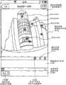
接着,如图31所示,显示控制单元34控制显示器315以显示预定范围图像,该预定范围图像是这样获取的:将用于如图28所示的预定范围图像的预定范围信息的参数(x,y)保持不变,同时将虚拟照相机IC的视角逐渐地改变为预定视角(步骤S203)。图31是示出具有预定视角的预定范围图像的示意图。在此,图31中所示的预定范围图像的视角比图28中所示的预定范围图像的视角大,因此允许用户观看更宽的范围。Next, as shown in FIG. 31 , the
然后,显示控制单元34控制显示器315以显示图31中所示的预定范围图像,该预定范围图像是这样获取的:将用于图31中所示的预定范围图像的视角保持不变,同时,将预定范围图像的中心定在上面步骤S202所读取的预定范围信息的参数(x,y)上(步骤S204)。Then, the
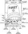
然后,显示控制单元34逐渐地减小虚拟照相机IC的视角,同时将用于图32中所示的预定范围图像的预定范围信息的参数(x,y)保持不变,以便于显示例如图33所示的预定范围图像,并且进一步减小视角以显示例如图34中所示的预定范围图像(部分图像P1)(步骤S205)。图32和图33是示出在显示对应于被显示的缩略图的预定范围图像之前,所显示的预定范围图像的示意图。图34是示出对应于缩略图的预定范围图像的示意图。Then, the
本实施例的主要效果The main effect of this embodiment
如上所述,在本实施例中,通信终端3能够在全景图像中显示用于预定范围区域的缩略图,并且接受预定缩略图的选择,以便于在全景图像中显示对应于在全景图像中所接受的缩略图的预定范围图像。这带来了这样的效果:用户能够轻易地找到想要的全景图像或者全景图像中的想要的预定范围的图像。As described above, in the present embodiment, the
此外,当存在多个全球面全景图像(所拍摄的图像)或者多个预定范围图像(关注点)时,用户能够将缩略图缩小成想要的缩略图并且然后指定预定范围图像。因此,当浏览预定图像时,用户不会迷惑。这带来了这样的效果:用户能够轻易地找到想要的全球面全景图像或者全球面全景图像中的想要的预定范围的图像。Furthermore, when there are a plurality of global panorama images (pictured images) or a plurality of predetermined-range images (points of interest), the user can reduce the thumbnails to desired ones and then designate the predetermined-range images. Therefore, the user is not confused when viewing predetermined images. This brings about the effect that the user can easily find a desired spherical panoramic image or an image of a desired predetermined range in the spherical panoramic image.
第二实施例second embodiment
接着,使用图35和图36,将描述本发明的第二实施例。在以上第一实施例中图像处理系统5设定场景,而在本实施例中,通信终端3'设定场景。Next, using Fig. 35 and Fig. 36, a second embodiment of the present invention will be described. In the above first embodiment, the
实施例的硬件配置The hardware configuration of the embodiment
本实施例的硬件配置与第一实施例的硬件配置相同,因此将省略对其的描述。The hardware configuration of this embodiment is the same as that of the first embodiment, and thus description thereof will be omitted.
实施例的功能配置Functional configuration of the embodiment
接着,将使用图35描述本实施例的功能配置。图35是根据本实施例的通信终端的功能方框图。如图13中所示的,第一实施例中的图像处理系统5包括场景设定单元52,而本实施不同于第一实施例的在于,如图35所示的,通信终端3'包括场景设定单元35。其他的功能配置与第一实施例的功能配置相同;因此,对相同的功能给出相同的标记并且将省略对其的描述。Next, the functional configuration of the present embodiment will be described using FIG. 35 . Fig. 35 is a functional block diagram of the communication terminal according to the present embodiment. As shown in FIG. 13, the
本实施例的场景设定单元35是这样的功能或装置:根据从SRAM113装载的并且被用在DRAM114中的、用于通信终端3'的程序,通过操作由来自CPU111的命令驱动的、图10所示的任何一个组成元件而实现。基于存储在通信终端3'的存储单元3000中的所拍摄图像的数据,场景设定单元35设定由所拍摄图像表示人物、风景、建筑和其他中的哪个场景。用于该设定的方法与第一实施例中,通过场景设定单元52进行的处理相同。The
实施例的处理和操作Processing and Operation of the Examples
接着,使用图20至图22以及图36,将描述本实施例的处理和操作。图36是示出本实施例中的预定范围的设定过程的屏幕的例子。Next, using FIG. 20 to FIG. 22 and FIG. 36 , processing and operation of the present embodiment will be described. FIG. 36 is an example of a screen showing a setting procedure of a predetermined range in this embodiment.
在第一实施例中,如图21所示,通信终端3不设定预定范围图像的场景,而是如图20的步骤S46所示的,图像处理系统5设定预定范围图像的场景。然而,在本实施例中,在图21的步骤S41-4和S41-5之间,通信终端3'设定设定预定范围图像的场景。In the first embodiment, as shown in FIG. 21 , the
在本实施例中,与第一实施例的方式相同,如图36所示,在图22中接受预定范围的设定之后,显示器控制单元34控制显示器315将用于从用户接受对场景的选择的场景选择菜单3114显示在预定范围图像显示区域3110中。场景选择菜单3114为用户显示按钮,来选择人物、风景、建筑和其他场景中的任何一个。操作输入接受单元32识别出按压了其中任何一个按钮,并且场景设定单元最终设定场景。In this embodiment, in the same manner as the first embodiment, as shown in FIG. 36, after accepting the setting of the predetermined range in FIG. The
如第一实施例中的图21的步骤41-5所示的,除场景之外的预定范围管理信息被存储在预定范围管理DB3001中,而在本实施例中,包括场景的预定范围管理信息被存储在预定范围管理DB3001中。包括场景的预定范围管理信息,被直接或者经由图像处理系统5,从通信终端3'发送至图像管理系统7,以便于以图20的步骤S48相同的方式,通过图像管理系统7被存储在预定范围管理DB7002中,并且通过图像管理系统7进行管理。结果是,包括场景的预定范围管理信息在图像共享系统中被管理,并且因此可以被其他用户获取。As shown in step 41-5 of FIG. 21 in the first embodiment, predetermined range management information other than scenes is stored in predetermined
本实施例的主要效果The main effect of this embodiment
如上所述,在本实施例中,用户能够设定预定范围图像的场景。在第一实施例的效果之外,这还带来了这样的效果:用户可以将预定范围图像作为用户想要的场景注册在图像共享系统中。As described above, in the present embodiment, the user can set the scene of a predetermined range image. In addition to the effects of the first embodiment, this brings about the effect that the user can register a predetermined range image as a scene desired by the user in the image sharing system.
第三实施例third embodiment
接着,使用图37和图38,将描述本发明的第三实施例。在第一实施例中,在通信终端3中创建缩略图,而在本实施例中,在图像管理系统7'中创建缩略图,这是本实施例的特征。Next, using Fig. 37 and Fig. 38, a third embodiment of the present invention will be described. In the first embodiment, thumbnail images are created in
实施例的硬件配置The hardware configuration of the embodiment
本实施例的硬件配置与第一实施例的硬件配置相同,并且因此将省略对其的描述。The hardware configuration of the present embodiment is the same as that of the first embodiment, and thus description thereof will be omitted.
实施例的功能配置Functional configuration of the embodiment
接着,将使用图37描述本实施例的功能配置。图37是第三实施例的图像管理系统7'的功能方框图。如图13所示,在第一实施例中,通信终端3包括创建单元33,而本实施不同于第一实施例的在于,如图37所示,图像管理系统7'包括创建单元73。其他的功能配置与第一实施例的功能配置相同。因此,对相同的功能给出相同的标记,并且将省略对其的描述。Next, the functional configuration of the present embodiment will be described using FIG. 37 . Fig. 37 is a functional block diagram of the image management system 7' of the third embodiment. As shown in FIG. 13 , in the first embodiment, the
图像管理系统的功能配置Function configuration of image management system
接着,将使用图37详细描述图像管理系统7'的功能配置。只有不同于第一实施例的创建单元的创建单元73被进行描述。Next, the functional configuration of the image management system 7' will be described in detail using FIG. 37 . Only the
创建单元73主要是由如12所示的CPU501的处理而完成。基于由存储/提取单元39读取的预定范围管理信息(图像识别信息)所识别的全球面全景图像中的预定范围图像,创建单元73创建为预定范围图像创建缩略图,并且还创建用于识别所创建的缩略图的缩略图识别信息。The
实施例的处理和操作Example Processing and Operation
接着,将使用图18至图38描述本实施例的处理和操作。图38是示出第三实施例中的,下载所拍摄图像和预定范围管理信息的过程的时序图。在本实施例中,执行与第一实施例中图18的步骤S21至S30相同的过程;因此将使用图38描述这过程之后的过程。Next, processing and operation of the present embodiment will be described using FIGS. 18 to 38 . Fig. 38 is a sequence diagram showing a procedure of downloading captured images and predetermined range management information in the third embodiment. In the present embodiment, the same process as steps S21 to S30 of FIG. 18 in the first embodiment is performed; therefore, processes subsequent to this process will be described using FIG. 38 .
如图38所示,基于由存储/提取单元39读取的预定范围管理信息(图像识别信息)所识别的全球面全景图像中的预定范围图像,创建单元73创建用于预定范围图像的缩略图,并且还创建用于识别所创建缩略图的缩略图识别信息。As shown in FIG. 38 , the creating
然后,发送/接收单元71以图18所示的步骤S31相同的方式,将图18中所示的步骤S29所读取的拍摄图像和图18中所示的步骤S30所读取的预定范围管理信息发送至通信终端3b,并且此外,还发送图38中所示的步骤S130所创建的缩略图和缩略图识别信息(步骤S131)。结果是,通信终端3b的发送/接收单元31接收所拍摄的图像、缩略图、预定范围管理信息和缩略图识别信息,并且因此终止对所拍摄图像的下载。应注意的是,在上面步骤S130所创建的缩略图识别信息与图像识别信息、预定范围管理信息和预定范围管理信息的相关信息是关联的。Then, the transmitting/receiving
然后,存储/提取单元39将在图38所示的步骤S131中下载的所拍摄图像和缩略图存储在存储单元3000中,并且将在上面步骤S131中下载的预定范围管理信息存储在存储单元3000的预定范围管理DB3001中(图38中所示的步骤S132)。存储在预定范围管理DB3001中的预定范围管理信息组成具有与图16相同形式的管理表格。Then, the storage/
然后,以图18所示的步骤S33相同的方式,基于所拍摄图像,通信终端3b的创建单元33创建例如图16所示的全球面全景图像,并且显示控制单元34控制通信终端3b的显示器315以显示全球面全景图像(图38中所示的步骤S133)。Then, in the same manner as step S33 shown in FIG. 18 , based on the captured image, the
本实施例的主要效果The main effect of this embodiment
如上所述,在本实施例中,图像管理系统7'还能够创建缩略图。在第一实施例的效果之外,这还带来这样的效果:在通信终端上不需要安装用于创建缩略图的任何程序。As described above, in this embodiment, the image management system 7' is also capable of creating thumbnail images. In addition to the effects of the first embodiment, this brings about the effect that no program for creating thumbnails needs to be installed on the communication terminal.
实施例的补充Example Supplement
上述实施例中的图像处理系统5和图像管理系统7可以用一台计算机建造,或者可以用任意地分配有单元的分割(功能或者方法)的多台计算机来建造。The
例如存储上述实施例的程序的CD-ROM和存储程序的HD504的记录介质,可以被本土地性地或者国际性地提供为程序产品。A recording medium such as a CD-ROM storing the program of the above-described embodiments and an
上述实施例用如同图16所示的预定范围管理表格的形式来管理预定范围管理信息,但是本实施例不限于此,而可以用图39所示的URL的形式管理预定范围管理信息。图39是示出链路信息描述的示意图。The above embodiment manages the predetermined range management information in the form of the predetermined range management table as shown in FIG. Fig. 39 is a diagram showing link information description.
在图25中的步骤S108缩小预定范围管理信息之后,第一实施例在步骤S109创建缩略图,但是本实施例不限于此。例如,显示控制单元34可以用没有被存储/提取单元39缩小的预定范围管理信息来显示所有缩略图。After narrowing down the predetermined range management information in step S108 in FIG. 25, the first embodiment creates thumbnails in step S109, but the embodiment is not limited thereto. For example, the
如上所述,在本实施例中,通信终端可以将用于预定范围图像的缩略图显示在全景图像中,并且接受预定缩略图的选择,以便于显示对应于所接受的缩略图的预定范围图像。这带来这样的效果:用户可以轻易地找到想要的全景图像或者全景图像中的想要的预定范围图像。As described above, in this embodiment, the communication terminal can display the thumbnails for the images in the predetermined range in the panoramic image, and accept the selection of the predetermined thumbnails, so as to display the images in the predetermined range corresponding to the accepted thumbnails . This brings about the effect that the user can easily find a desired panorama image or a desired predetermined range image in the panorama image.
尽管已经相关与具体实施例对本发明进行了描述,以完整和清楚的公开,但是所附的权利要求并不因此而被限制,而是被解释为本领域技术人员可以实现的所有修改和替换结构的实施,均完全落入在此提出的基本教导之中。While the invention has been described in relation to specific embodiments for complete and clear disclosure, the appended claims are not so limited, but are to be construed as all modifications and alternative constructions that can be achieved by those skilled in the art implementation, all falling fully within the basic teachings presented here.
Claims (11)
Translated fromChineseApplications Claiming Priority (4)
| Application Number | Priority Date | Filing Date | Title |
|---|---|---|---|
| JP2012124567 | 2012-05-31 | ||
| JP2012-124567 | 2012-05-31 | ||
| JP2013-053565 | 2013-03-15 | ||
| JP2013053565AJP6186775B2 (en) | 2012-05-31 | 2013-03-15 | Communication terminal, display method, and program |
Publications (2)
| Publication Number | Publication Date |
|---|---|
| CN103458180Atrue CN103458180A (en) | 2013-12-18 |
| CN103458180B CN103458180B (en) | 2017-03-01 |
Family
ID=48745616
Family Applications (1)
| Application Number | Title | Priority Date | Filing Date |
|---|---|---|---|
| CN201310210163.8AActiveCN103458180B (en) | 2012-05-31 | 2013-05-30 | Communication terminal and the display packing using communication terminal displays image |
Country Status (4)
| Country | Link |
|---|---|
| US (1) | US9756242B2 (en) |
| EP (1) | EP2669822A3 (en) |
| JP (1) | JP6186775B2 (en) |
| CN (1) | CN103458180B (en) |
Cited By (7)
| Publication number | Priority date | Publication date | Assignee | Title |
|---|---|---|---|---|
| CN106454065A (en)* | 2015-08-04 | 2017-02-22 | 佳能株式会社 | Information processing apparatus and control method therefor |
| CN107111432A (en)* | 2014-12-31 | 2017-08-29 | 诺基亚技术有限公司 | Image-guidance |
| CN107710108A (en)* | 2015-07-03 | 2018-02-16 | 诺基亚技术有限公司 | Content-browsing |
| CN107925740A (en)* | 2015-07-21 | 2018-04-17 | 株式会社理光 | Image management system, image management method and program |
| CN109076262A (en)* | 2016-05-13 | 2018-12-21 | 索尼公司 | File generating device, file generating method, and reproducing device and reproducing method |
| CN110114759A (en)* | 2016-09-20 | 2019-08-09 | 佳能株式会社 | Information processing unit, its control method and computer program |
| CN111723271A (en)* | 2020-07-15 | 2020-09-29 | 山东省计量科学研究院 | A holographic navigation display system and method for electronic museum of weights, measures and measurement science knowledge |
Families Citing this family (48)
| Publication number | Priority date | Publication date | Assignee | Title |
|---|---|---|---|---|
| JP6446766B2 (en)* | 2013-07-08 | 2019-01-09 | 株式会社リコー | Program, display control device, recording medium, and display control system |
| JP6167703B2 (en) | 2013-07-08 | 2017-07-26 | 株式会社リコー | Display control device, program, and recording medium |
| KR20150028066A (en)* | 2013-09-05 | 2015-03-13 | 엘지전자 주식회사 | Mobile terminal and control method thereof |
| JP5835384B2 (en) | 2014-03-18 | 2015-12-24 | 株式会社リコー | Information processing method, information processing apparatus, and program |
| JP5835383B2 (en) | 2014-03-18 | 2015-12-24 | 株式会社リコー | Information processing method, information processing apparatus, and program |
| US9906720B2 (en) | 2014-12-05 | 2018-02-27 | Ricoh Company, Ltd. | Service system, information processing apparatus, and service providing method |
| JP6682821B2 (en) | 2014-12-05 | 2020-04-15 | 株式会社リコー | Service system, information processing device, service providing method |
| WO2016093063A1 (en)* | 2014-12-08 | 2016-06-16 | 株式会社リコー | Image management system, image management method, and program |
| JP6497965B2 (en)* | 2015-02-23 | 2019-04-10 | キヤノン株式会社 | Image processing apparatus and image processing method |
| US9924093B1 (en)* | 2015-05-01 | 2018-03-20 | Hoyos Integrity Corporation | Method and apparatus for displaying panoramic images |
| JP6503881B2 (en)* | 2015-05-20 | 2019-04-24 | 株式会社リコー | Content providing system, information processing apparatus, program, content reproducing method |
| JP6613686B2 (en)* | 2015-07-29 | 2019-12-04 | 株式会社リコー | Movie display device, movie display method, and program |
| JP2017040687A (en)* | 2015-08-17 | 2017-02-23 | 株式会社リコー | Image display system, information processing apparatus, image display method, and program |
| JP6555026B2 (en)* | 2015-09-04 | 2019-08-07 | 株式会社リコー | Information provision system |
| JP6615545B2 (en)* | 2015-09-15 | 2019-12-04 | 株式会社トプコン | Image processing apparatus, image processing method, and image processing program |
| US9767363B2 (en) | 2015-10-30 | 2017-09-19 | Google Inc. | System and method for automatic detection of spherical video content |
| JP6617547B2 (en)* | 2015-12-11 | 2019-12-11 | 株式会社リコー | Image management system, image management method, and program |
| JP6665558B2 (en)* | 2016-01-29 | 2020-03-13 | 株式会社リコー | Image management system, image management method, image communication system, and program |
| CN108702441A (en) | 2016-02-24 | 2018-10-23 | 株式会社理光 | Image processing equipment, image processing system and program |
| US10652459B2 (en) | 2016-03-07 | 2020-05-12 | Ricoh Company, Ltd. | Information processing system, information processing method, and non-transitory computer-readable storage medium |
| EP3432567A4 (en) | 2016-03-15 | 2019-02-27 | Ricoh Company, Ltd. | IMAGE PROCESSING DEVICE, IMAGE PROCESSING METHOD, AND IMAGE PROCESSING SYSTEM |
| KR102590132B1 (en)* | 2016-03-24 | 2023-10-18 | 삼성전자주식회사 | Display device and control method of the display device |
| US20170309060A1 (en)* | 2016-04-21 | 2017-10-26 | Honeywell International Inc. | Cockpit display for degraded visual environment (dve) using millimeter wave radar (mmwr) |
| KR102632795B1 (en) | 2016-09-21 | 2024-02-02 | 삼성전자주식회사 | Method for displaying navigator related to contents and electronic device for the same |
| JP6992338B2 (en)* | 2016-09-30 | 2022-01-13 | 株式会社リコー | Communication system, communication management method, program, system and communication method |
| JP2018056889A (en)* | 2016-09-30 | 2018-04-05 | 株式会社リコー | Display terminal, display method, and program |
| CN107993276B (en)* | 2016-10-25 | 2021-11-23 | 杭州海康威视数字技术股份有限公司 | Panoramic image generation method and device |
| US10176615B2 (en)* | 2016-12-13 | 2019-01-08 | Topcon Corporation | Image processing device, image processing method, and image processing program |
| KR102697559B1 (en)* | 2016-12-22 | 2024-08-23 | 삼성전자주식회사 | Display control method, storage medium and electronic device for displaying image |
| US10417276B2 (en)* | 2017-05-15 | 2019-09-17 | Adobe, Inc. | Thumbnail generation from panoramic images |
| WO2019031468A1 (en)* | 2017-08-07 | 2019-02-14 | ソニー株式会社 | Transmission device, transmission method, reception device, reception method and imaging device |
| JP6793615B2 (en)* | 2017-09-22 | 2020-12-02 | Kddi株式会社 | Display devices, display programs and display systems |
| JP7031228B2 (en) | 2017-10-26 | 2022-03-08 | 株式会社リコー | Program, image display method, image display system, information processing device |
| JP6503098B1 (en)* | 2018-01-30 | 2019-04-17 | フォージビジョン株式会社 | Image processing apparatus, image processing program and image processing method |
| JP7081473B2 (en) | 2018-03-02 | 2022-06-07 | 株式会社リコー | Imaging optical system, imaging system and imaging device |
| EP3537399B1 (en) | 2018-03-05 | 2021-03-31 | Ricoh Company, Ltd. | Imaging optical system, imaging system, and imaging apparatus |
| US10852503B2 (en) | 2018-03-20 | 2020-12-01 | Ricoh Company, Ltd. | Joint structure |
| CN111886542B (en) | 2018-03-20 | 2022-08-30 | 株式会社理光 | Optical system and imaging device |
| JP7124366B2 (en) | 2018-03-20 | 2022-08-24 | 株式会社リコー | Imaging element fixing structure and imaging device |
| JP2019164303A (en) | 2018-03-20 | 2019-09-26 | 株式会社リコー | Optical system and imaging apparatus |
| JP7164831B2 (en)* | 2018-03-30 | 2022-11-02 | 株式会社リコー | Communication management system, communication system, communication method, and program |
| JP7273477B2 (en)* | 2018-10-02 | 2023-05-15 | パイオニア株式会社 | Display control device, display control method and display control program |
| JP7268372B2 (en)* | 2019-01-31 | 2023-05-08 | 株式会社リコー | Imaging device |
| JP6679784B2 (en)* | 2019-03-12 | 2020-04-15 | キヤノン株式会社 | Image processing apparatus and image processing method |
| JP7625808B2 (en)* | 2020-08-31 | 2025-02-04 | 株式会社リコー | Image communication system and image display method |
| US20250008165A1 (en)* | 2021-11-30 | 2025-01-02 | Nippon Telegraph And Telephone Corporation | Video processing apparatus, method, and program |
| KR20230168859A (en)* | 2022-06-08 | 2023-12-15 | 현대모비스 주식회사 | Vehicle lighting device and method of operating thereof |
| CN118015939B (en)* | 2024-03-13 | 2024-08-16 | 西藏自然科学博物馆 | Holographic navigation display system method for electronic museum for measuring science popularization knowledge |
Citations (5)
| Publication number | Priority date | Publication date | Assignee | Title |
|---|---|---|---|---|
| CN101102489A (en)* | 2006-07-04 | 2008-01-09 | 索尼株式会社 | Information processing apparatus, method and program |
| US20080247636A1 (en)* | 2006-03-20 | 2008-10-09 | Siemens Power Generation, Inc. | Method and System for Interactive Virtual Inspection of Modeled Objects |
| CN101957495A (en)* | 2009-07-16 | 2011-01-26 | 纽约州州立大学研究基金会 | Virtual telemicroscope |
| CN102393841A (en)* | 2010-07-07 | 2012-03-28 | 索尼计算机娱乐公司 | Image processing apparatus and image processing method |
| CN102461153A (en)* | 2009-06-09 | 2012-05-16 | 索尼公司 | Control device, camera system, and program |
Family Cites Families (35)
| Publication number | Priority date | Publication date | Assignee | Title |
|---|---|---|---|---|
| JPH04258825A (en) | 1991-02-12 | 1992-09-14 | Hitachi Maxell Ltd | Adhesive lamination type optical information recording medium |
| JPH04307483A (en) | 1991-04-04 | 1992-10-29 | Hokkaido Nippon Denki Software Kk | Floppy disk device fault prevention system |
| US6396941B1 (en)* | 1996-08-23 | 2002-05-28 | Bacus Research Laboratories, Inc. | Method and apparatus for internet, intranet, and local viewing of virtual microscope slides |
| US6272235B1 (en)* | 1997-03-03 | 2001-08-07 | Bacus Research Laboratories, Inc. | Method and apparatus for creating a virtual microscope slide |
| JPH10336705A (en)* | 1997-06-02 | 1998-12-18 | Canon Inc | Compound eye camera |
| CN1214614C (en)* | 1998-04-10 | 2005-08-10 | 株式会社理光 | Image processing method, image processing device and recording medium |
| JP2001186334A (en)* | 1999-12-27 | 2001-07-06 | Canon Inc | Image processing apparatus, image processing system, image processing method, and storage medium |
| US20020063725A1 (en)* | 2000-11-30 | 2002-05-30 | Virtuallylisted Llc | Method and apparatus for capturing and presenting panoramic images for websites |
| JP4258825B2 (en) | 2001-03-01 | 2009-04-30 | 富士フイルム株式会社 | Electronic camera, image providing system and method thereof |
| JP2003110983A (en)* | 2001-09-28 | 2003-04-11 | Canon Inc | Imaging device, image management device, image management system, control method of imaging device, image management method, recording medium, and program |
| US20100002070A1 (en)* | 2004-04-30 | 2010-01-07 | Grandeye Ltd. | Method and System of Simultaneously Displaying Multiple Views for Video Surveillance |
| JP2005025548A (en)* | 2003-07-03 | 2005-01-27 | Minolta Co Ltd | Processing device, output method and output program for image with annotation information |
| JP4837248B2 (en)* | 2003-10-29 | 2011-12-14 | 京セラ株式会社 | Image display device and control method of image display device |
| US8427538B2 (en)* | 2004-04-30 | 2013-04-23 | Oncam Grandeye | Multiple view and multiple object processing in wide-angle video camera |
| JP4494196B2 (en)* | 2004-12-27 | 2010-06-30 | 京セラ株式会社 | Image display device |
| JP2007018352A (en)* | 2005-07-08 | 2007-01-25 | Olympus Imaging Corp | Image display device, image display program, image display method and recording medium |
| JP4592099B2 (en)* | 2005-09-29 | 2010-12-01 | キヤノン株式会社 | Image display device and image display method |
| KR101329470B1 (en)* | 2005-11-11 | 2013-11-13 | 소니 주식회사 | Image processing device, image processing method, and recording medium containing program thereof |
| WO2007124664A1 (en)* | 2006-04-29 | 2007-11-08 | Shanghai Jietu Software Co., Ltd. | Apparatus and method for collecting panorama graph with location information and method for building, annotating and switching panorama electric map service |
| JP4307483B2 (en) | 2006-12-22 | 2009-08-05 | キヤノン株式会社 | Imaging apparatus, image display apparatus, control method thereof, and computer program |
| JP4050777B1 (en)* | 2007-04-06 | 2008-02-20 | 株式会社デジタルマックス | Image display system |
| US20100122208A1 (en)* | 2007-08-07 | 2010-05-13 | Adam Herr | Panoramic Mapping Display |
| JP5326910B2 (en)* | 2009-01-20 | 2013-10-30 | ソニー株式会社 | Information processing apparatus, information processing method, and program |
| JP5232107B2 (en) | 2009-09-02 | 2013-07-10 | 株式会社ニコンシステム | Image display method, program, image display apparatus, and imaging apparatus |
| JP5385059B2 (en) | 2009-09-07 | 2014-01-08 | 株式会社ニコンシステム | Image display method, program, image display apparatus, and imaging apparatus |
| US8599219B2 (en)* | 2009-09-18 | 2013-12-03 | Adobe Systems Incorporated | Methods and apparatuses for generating thumbnail summaries for image collections |
| US8619098B2 (en)* | 2009-09-18 | 2013-12-31 | Adobe Systems Incorporated | Methods and apparatuses for generating co-salient thumbnails for digital images |
| JP5464955B2 (en) | 2009-09-29 | 2014-04-09 | 株式会社ソニー・コンピュータエンタテインメント | Panorama image display device |
| KR20110052124A (en)* | 2009-11-12 | 2011-05-18 | 삼성전자주식회사 | Panorama image generation and inquiry method and mobile terminal using the same |
| JP5340895B2 (en)* | 2009-11-24 | 2013-11-13 | 株式会社ソニー・コンピュータエンタテインメント | Image data creation support apparatus and image data creation support method |
| US20120019614A1 (en)* | 2009-12-11 | 2012-01-26 | Tessera Technologies Ireland Limited | Variable Stereo Base for (3D) Panorama Creation on Handheld Device |
| JP2011211696A (en)* | 2010-03-10 | 2011-10-20 | Nikon Corp | Image data processing system, image data processing program, and image data processing apparatus |
| WO2011149558A2 (en)* | 2010-05-28 | 2011-12-01 | Abelow Daniel H | Reality alternate |
| JP5134651B2 (en)* | 2010-07-07 | 2013-01-30 | 株式会社ソニー・コンピュータエンタテインメント | Image display device and image display method |
| US20130235084A1 (en)* | 2012-03-12 | 2013-09-12 | Chuan-Wei Wu | Multi-source multiple documents comparison display (presentation or discussion) system |
- 2013
- 2013-03-15JPJP2013053565Apatent/JP6186775B2/enactiveActive
- 2013-05-24USUS13/902,124patent/US9756242B2/enactiveActive
- 2013-05-29EPEP13169681.7Apatent/EP2669822A3/ennot_activeCeased
- 2013-05-30CNCN201310210163.8Apatent/CN103458180B/enactiveActive
Patent Citations (5)
| Publication number | Priority date | Publication date | Assignee | Title |
|---|---|---|---|---|
| US20080247636A1 (en)* | 2006-03-20 | 2008-10-09 | Siemens Power Generation, Inc. | Method and System for Interactive Virtual Inspection of Modeled Objects |
| CN101102489A (en)* | 2006-07-04 | 2008-01-09 | 索尼株式会社 | Information processing apparatus, method and program |
| CN102461153A (en)* | 2009-06-09 | 2012-05-16 | 索尼公司 | Control device, camera system, and program |
| CN101957495A (en)* | 2009-07-16 | 2011-01-26 | 纽约州州立大学研究基金会 | Virtual telemicroscope |
| CN102393841A (en)* | 2010-07-07 | 2012-03-28 | 索尼计算机娱乐公司 | Image processing apparatus and image processing method |
Cited By (13)
| Publication number | Priority date | Publication date | Assignee | Title |
|---|---|---|---|---|
| CN107111432A (en)* | 2014-12-31 | 2017-08-29 | 诺基亚技术有限公司 | Image-guidance |
| CN107111432B (en)* | 2014-12-31 | 2021-06-04 | 诺基亚技术有限公司 | Image navigation |
| US10782868B2 (en) | 2014-12-31 | 2020-09-22 | Nokia Technologies Oy | Image navigation |
| CN107710108B (en)* | 2015-07-03 | 2020-07-31 | 诺基亚技术有限公司 | Content browsing |
| CN107710108A (en)* | 2015-07-03 | 2018-02-16 | 诺基亚技术有限公司 | Content-browsing |
| US10761595B2 (en) | 2015-07-03 | 2020-09-01 | Nokia Technologies Oy | Content browsing |
| CN107925740A (en)* | 2015-07-21 | 2018-04-17 | 株式会社理光 | Image management system, image management method and program |
| CN106454065B (en)* | 2015-08-04 | 2019-12-13 | 佳能株式会社 | Information processing apparatus and control method thereof |
| CN106454065A (en)* | 2015-08-04 | 2017-02-22 | 佳能株式会社 | Information processing apparatus and control method therefor |
| CN109076262A (en)* | 2016-05-13 | 2018-12-21 | 索尼公司 | File generating device, file generating method, and reproducing device and reproducing method |
| CN109076262B (en)* | 2016-05-13 | 2022-07-12 | 索尼公司 | File generation apparatus and file generation method, and reproduction apparatus and reproduction method |
| CN110114759A (en)* | 2016-09-20 | 2019-08-09 | 佳能株式会社 | Information processing unit, its control method and computer program |
| CN111723271A (en)* | 2020-07-15 | 2020-09-29 | 山东省计量科学研究院 | A holographic navigation display system and method for electronic museum of weights, measures and measurement science knowledge |
Also Published As
| Publication number | Publication date |
|---|---|
| EP2669822A2 (en) | 2013-12-04 |
| US20130326419A1 (en) | 2013-12-05 |
| US9756242B2 (en) | 2017-09-05 |
| EP2669822A3 (en) | 2015-06-10 |
| CN103458180B (en) | 2017-03-01 |
| JP6186775B2 (en) | 2017-08-30 |
| JP2014006880A (en) | 2014-01-16 |
Similar Documents
| Publication | Publication Date | Title |
|---|---|---|
| CN103458180B (en) | Communication terminal and the display packing using communication terminal displays image | |
| US12328527B2 (en) | Image management system, image management method, and computer program product | |
| JP2014112302A (en) | Prescribed area management system, communication method, and program | |
| JP5920057B2 (en) | Transmission device, image sharing system, transmission method, and program | |
| JP7420126B2 (en) | System, management system, image management method, and program | |
| JP6617547B2 (en) | Image management system, image management method, and program | |
| CN107925740A (en) | Image management system, image management method and program | |
| JP6011117B2 (en) | Reception device, image sharing system, reception method, and program | |
| JP6304300B2 (en) | Transmitting apparatus, communication method, program, and receiving apparatus | |
| JP2018026642A (en) | Image management system, image communication system, image management method, and program | |
| JP2014120878A (en) | Predetermined-zone management system, predetermined-zone management method, and program | |
| JP5942637B2 (en) | Additional information management system, image sharing system, additional information management method, and program | |
| JP2017182548A (en) | Image management system, image management method, image communication system, and program | |
| JP6508288B2 (en) | SYSTEM, IMAGE SHARING SYSTEM, COMMUNICATION METHOD, AND PROGRAM | |
| JP6233451B2 (en) | Image sharing system, communication method and program | |
| JP2017037423A (en) | Image management system, image management method, image communication system, and program | |
| JP2016194782A (en) | Image management system, communication terminal, communication system, image management method, and program |
Legal Events
| Date | Code | Title | Description |
|---|---|---|---|
| C06 | Publication | ||
| PB01 | Publication | ||
| C10 | Entry into substantive examination | ||
| SE01 | Entry into force of request for substantive examination | ||
| GR01 | Patent grant | ||
| GR01 | Patent grant |