CN103457023A - Compact type conformal PIFA array antenna on UHF frequency band - Google Patents
Compact type conformal PIFA array antenna on UHF frequency bandDownload PDFInfo
- Publication number
- CN103457023A CN103457023ACN2013104056815ACN201310405681ACN103457023ACN 103457023 ACN103457023 ACN 103457023ACN 2013104056815 ACN2013104056815 ACN 2013104056815ACN 201310405681 ACN201310405681 ACN 201310405681ACN 103457023 ACN103457023 ACN 103457023A
- Authority
- CN
- China
- Prior art keywords
- antenna
- inverted
- pifa
- conformal
- flexible dielectric
- Prior art date
- Legal status (The legal status is an assumption and is not a legal conclusion. Google has not performed a legal analysis and makes no representation as to the accuracy of the status listed.)
- Pending
Links
- PEZNEXFPRSOYPL-UHFFFAOYSA-N(bis(trifluoroacetoxy)iodo)benzeneChemical compoundFC(F)(F)C(=O)OI(OC(=O)C(F)(F)F)C1=CC=CC=C1PEZNEXFPRSOYPL-UHFFFAOYSA-N0.000titleclaimsabstractdescription20
- 239000002184metalSubstances0.000claimsdescription28
- 239000000463materialSubstances0.000claimsdescription6
- 238000005452bendingMethods0.000claimsdescription5
- 238000000034methodMethods0.000claimsdescription4
- -1polytetrafluoroethylenePolymers0.000claimsdescription3
- 229920001343polytetrafluoroethylenePolymers0.000claimsdescription3
- 239000004810polytetrafluoroethyleneSubstances0.000claimsdescription3
- 230000005855radiationEffects0.000abstractdescription10
- 238000004519manufacturing processMethods0.000abstractdescription2
- 238000004891communicationMethods0.000description4
- 238000010586diagramMethods0.000description4
- 230000005404monopoleEffects0.000description4
- 238000005516engineering processMethods0.000description3
- 239000000969carrierSubstances0.000description2
- 238000010295mobile communicationMethods0.000description1
Images


Landscapes
- Variable-Direction Aerials And Aerial Arrays (AREA)
- Details Of Aerials (AREA)
Abstract
Translated fromChineseDescription
Translated fromChinese技术领域technical field
本发明涉及一种PIFA阵列天线,特别是一种UHF频段紧凑型共形PIFA阵列天线。The invention relates to a PIFA array antenna, in particular to a UHF frequency band compact conformal PIFA array antenna.
背景技术Background technique
天线是无线系统中必不可少的组成部分,随着科学技术的不断进步,无线通信技术得到了迅猛的发展,在飞机、卫星、导弹等载体上,通信设备的数量和种类都达到了前所未有的程度,并且对天线的要求也越来越高,发展低剖面的小型化天线,并且可以与高速运动的载体共形的天线的要求变得越来越高。近几十年来,作为移动通信的重要频段,UHF频段天线小型化的课题研究吸引了越来越多的研究人员的关注。Antenna is an essential part of a wireless system. With the continuous advancement of science and technology, wireless communication technology has developed rapidly. On aircraft, satellites, missiles and other carriers, the number and types of communication equipment have reached unprecedented levels. The degree, and the requirements for antennas are getting higher and higher, and the requirements for developing low-profile miniaturized antennas and antennas that can conform to high-speed moving carriers are becoming higher and higher. In recent decades, as an important frequency band for mobile communications, the miniaturization of antennas in the UHF band has attracted more and more researchers' attention.
因全向辐射特性、结构简单和成本低廉等特点,单极子天线在现代通信领域中得到了广泛应用,例如车载通信中的金属振子单极子天线,无线局域网中微带单极子天线等,但是当工作于UHF频段下时,由于物理长度较大等局限,限制了单极子天线的工程应用,所以其面临着小型化、共形化、低损耗、低成本等亟待解决的问题。然而当天线的尺寸小于λ/8 (λ为空气波长)时,天线的性能就会急剧恶化,所以如何实现低剖面,同时兼具宽频带,高增益的天线成为研究热点之一。Due to the characteristics of omnidirectional radiation, simple structure and low cost, monopole antennas have been widely used in the field of modern communications, such as metal oscillator monopole antennas in vehicle communications, microstrip monopole antennas in wireless local area networks, etc. , but when working in the UHF frequency band, due to limitations such as large physical length, the engineering application of monopole antennas is limited, so it faces urgent problems such as miniaturization, conformalization, low loss, and low cost. However, when the size of the antenna is smaller than λ/8 (λ is the wavelength of air), the performance of the antenna will deteriorate sharply. Therefore, how to achieve a low-profile, broadband, and high-gain antenna has become one of the research hotspots.
现有技术尚无一种同时实现低剖面、高增益并与载体共形的天线。In the prior art, there is no antenna that realizes low profile, high gain and conformal shape to the carrier at the same time.
发明内容Contents of the invention
本发明所解决的技术问题在于提供一种UHF频段紧凑型共形PIFA阵列天线。The technical problem solved by the present invention is to provide a UHF frequency band compact conformal PIFA array antenna.
实现本发明目的的技术解决方案为:一种UHF频段紧凑型共形PIFA阵列天线,包括介质圆柱体、柔性介质板、馈电网络、金属地和若干倒F天线单元,柔性介质板包覆在介质圆柱体的外侧面,馈电网络和由若干倒F天线单元组成等间距的水平阵列均印制在柔性介质板的外侧,馈电网络位于若干倒F天线单元的下方,为每个倒F天线单元馈电,柔性介质板的内侧馈电网络对应的位置印制金属地,柔性介质板上开有金属过孔,每个倒F天线单元均引入短路枝节,该短路枝节的末端穿过柔性介质板的金属过孔与金属地相连。The technical solution to realize the object of the present invention is: a compact conformal PIFA array antenna in the UHF frequency band, including a dielectric cylinder, a flexible dielectric plate, a feed network, a metal ground and several inverted F antenna units, and the flexible dielectric plate is wrapped in The outer surface of the dielectric cylinder, the feed network and the horizontal array composed of several inverted F antenna elements are all printed on the outside of the flexible dielectric plate, and the feed network is located under the several inverted F antenna elements. Antenna unit feed, metal ground is printed on the corresponding position of the inner feed network of the flexible dielectric board, metal via holes are opened on the flexible dielectric board, each inverted F antenna unit introduces a short-circuit stub, and the end of the short-circuit stub passes through the flexible The metal vias on the dielectric board are connected to the metal ground.
本发明与现有技术相比,其显著优点为:1)本发明将工作于UHF频段的1×4平面倒F阵列天线共形于介质圆柱体表面,实现了其低剖面和小型化,并且具有较高的增益;2)本发明的PIFA阵列天线可以实现在UHF频段共形于圆柱体表面,并且可以实现全向辐射;3)本发明提出了一种UHF频段紧凑型共形PIFA阵列天线,天线采用多次弯折技术实现低剖面,并将其共形于介质圆柱体的表面使得进一步减小截面积,同时小型化后的天线依然具备良好的全向辐射特性。此外在天线上引入的间断式调节枝节使得在使用过程中能够方便的对天线的工作频率进行调节。Compared with the prior art, the present invention has the following significant advantages: 1) The present invention conforms the 1×4 planar inverted F array antenna working in the UHF frequency band to the surface of the dielectric cylinder, realizing its low profile and miniaturization, and It has high gain; 2) The PIFA array antenna of the present invention can conform to the surface of the cylinder in the UHF frequency band, and can realize omnidirectional radiation; 3) The present invention proposes a compact conformal PIFA array antenna in the UHF frequency band , the antenna uses multiple bending technology to achieve a low profile, and conforms it to the surface of the dielectric cylinder to further reduce the cross-sectional area, while the miniaturized antenna still has good omnidirectional radiation characteristics. In addition, the discontinuous adjustment branch introduced on the antenna makes it easy to adjust the working frequency of the antenna during use.
下面结合附图对本发明作进一步详细描述。The present invention will be described in further detail below in conjunction with the accompanying drawings.
附图说明Description of drawings
图1为本发明的共形阵列天线的总体结构图。图中1为倒F天线单元,2为介质圆柱体,3为馈电网络,4为间断式调节枝节,5为短路枝节, 6为金属过孔、7为金属地、8为柔性介质板。FIG. 1 is a general structural diagram of the conformal array antenna of the present invention. In the figure, 1 is an inverted F antenna unit, 2 is a dielectric cylinder, 3 is a feed network, 4 is an intermittent adjustment branch, 5 is a short-circuit branch, 6 is a metal via, 7 is a metal ground, and 8 is a flexible dielectric board.
图2为本发明的共形阵列天线单元的俯视图,其中图(a)为主视图,图(b)为侧视图,图中6为金属通孔、7为金属地。Fig. 2 is a top view of the conformal array antenna unit of the present invention, wherein (a) is a front view, and (b) is a side view, in which 6 is a metal through hole and 7 is a metal ground.
图3为本发明的1×4平面天线阵列俯视图。图中2为介质圆柱体,3为馈电网络,4为间断式调节枝节,5为短路枝节。FIG. 3 is a top view of the 1×4 planar antenna array of the present invention. In the figure, 2 is a dielectric cylinder, 3 is a feed network, 4 is an intermittent adjustment branch, and 5 is a short-circuit branch.
图4为本发明的阵列天线单元反射系数结果图。Fig. 4 is a graph showing the reflection coefficient results of the array antenna unit of the present invention.
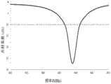
图5为本发明的平面阵列天线反射系数结果图。Fig. 5 is a graph showing the reflection coefficient results of the planar array antenna of the present invention.
图6为本发明的共形阵列天线反射系数结果图。Fig. 6 is a graph showing reflection coefficient results of the conformal array antenna of the present invention.
图7为本发明的共形阵列天线增益结果图。FIG. 7 is a diagram of gain results of the conformal array antenna of the present invention.
图8为本发明的共形阵列天线的辐射方向图。FIG. 8 is a radiation pattern diagram of the conformal array antenna of the present invention.
具体实施方式Detailed ways
结合图1,本发明的一种UHF频段紧凑型共形PIFA阵列天线,包括介质圆柱体2、柔性介质板8、馈电网络3、金属地7和若干倒F天线单元1,柔性介质板8包覆在介质圆柱体2的外侧面,馈电网络3和由若干倒F天线单元1组成等间距的水平阵列均印制在柔性介质板8的外侧,馈电网络3位于若干倒F天线单元1的下方,为每个倒F天线单元1馈电,柔性介质板8的内侧馈电网络3对应的位置印制金属地7,柔性介质板8上开有金属过孔6,每个倒F天线单元1均引入短路枝节5,该短路枝节5的末端穿过柔性介质板8的金属过孔6与金属地7相连。1, a UHF frequency band compact conformal PIFA array antenna of the present invention includes a
所述馈电网络3有一个输入端和若干个输出端,输出端的数量与倒F天线单元1的数量一致。The
所述倒F天线单元1的天线臂多次弯折后印制在柔性介质板8上,每次弯折的角度为九十度,倒F天线单元1的末端设置间断式调节枝节4。The antenna arm of the inverted-
所述柔性介质板8的材料的相对介电常数为2.2~4.4,其厚度为0.0004λ,其中λ为空气波长。The relative dielectric constant of the material of the flexible
所述介质圆柱体2的材料为相对介电常数为4.4~6的聚四氟乙烯材料。The material of the
所述介质圆柱体2的半径为16mm,倒F天线单元1的数量为四个,该四个倒F天线单元1组成等间距的水平阵列均匀包裹在介质圆柱体2的外侧面。The radius of the
所述馈电网络3为并馈馈电方式。The
所述金属过孔6的直径为0.0005λ,λ为空气波长。The diameter of the metal via
下面结合实施例对本发明进行具体描述:The present invention is specifically described below in conjunction with embodiment:
实施例1Example 1
一种UHF频段紧凑型共形阵列天线,如图1所示,包括介质圆柱体2、柔性介质板8、馈电网络3、金属地7和四个倒F天线单元1,其中,每个倒F天线单元1为多次弯折的倒F天线,弯折角度为九十度,天线单元制作在柔性介质板8上,并将柔性介质板8弯曲后粘贴于介质圆柱体2的外侧面进行共形设置,馈电网络3有一个输入端,四个输出端,每个输出端分别给每个倒F天线单元1馈电,倒F天线单元1的末端与间断式调节枝节4相连,同时每个倒F天线单元1引入短路枝节5,短路枝节5的末端穿过柔性介质板8上的金属过孔6与金属地7相连,天线工作的中心频率为432MHz,带宽为6MHz,并且中心频率的增益为0.16dB。A UHF frequency band compact conformal array antenna, as shown in Figure 1, includes a
倒F天线单元1如图2所示, 制作在相对介电常数2.2,厚度0.254mm的柔性介质板8上,由于该介质板非常薄,具有良好的柔韧性,可以弯曲后粘贴在介质圆柱体2的外侧面上,以此减小天线截面积,其中介质圆柱体2采用相对介电常数为4.4的聚四氟乙烯材料制作;倒F天线单元1采用多次弯折的方法使其获得低剖面,整体天线的高度为48mm,同时短路枝节5的引入也使得天线的尺寸得到进一步的减小,短路枝节5通过半径为0.2mm的金属过孔6和与柔性介质板8背面的金属地7相连。The inverted-
图3为本发明专利的平面1×4阵列天线俯视图,阵列天线的平面展开的面积为100.5mm×48mm,阵间距为25mm,图中倒F天线单元1末端处引入的间断式调节枝节4为天线工作频率的调整部分,以方便在实际使用过程进行工作频率的调整,馈电网络3采用一分四的并馈结构,在柔性介质板8上馈电网络3的背面,金属地7的面积为100.5mm×7mm。Fig. 3 is a top view of the planar 1×4 array antenna of the patent of the present invention. The area of the array antenna is 100.5mm×48mm, and the array spacing is 25mm. The
图4,图5,图6分别是本发明专利的倒F天线单元1,由倒F天线单元1组成的1×4水平阵列天线以及共形PIFA阵列天线的反射系数结果。图7为本发明专利共形PIFA阵列天线的增益结果,其中最高增益为0.16dB, ±1dB增益带宽为7%。图8为共形PIFA阵列天线的辐射方向图,该天线呈现出较好的全向性辐射特性。Figure 4, Figure 5, and Figure 6 are the reflection coefficient results of the inverted-
由上可知,本专利中利用多次弯折后小型化的倒F天线单元组成的1×4阵列天线,将其印制在柔性介质板上,并将柔性介质板弯曲后共形于介质圆柱体表面而构成共形辐射体,共形后的阵列天线可以进一步减小其截面积使之能安装在狭小的空间内,同时共形后的天线能实现拥有良好不圆度的全向性辐射特性。该天线充分利用倒F天线加工制作方便、精度高和成本低廉的优势,不仅实现了小型化,低剖面,并且同时得到了高增益和较好的全向辐射特性。As can be seen from the above, in this patent, the 1×4 array antenna composed of miniaturized inverted F antenna units after multiple bendings is used to print it on a flexible dielectric board, and bend the flexible dielectric board to conform to the dielectric cylinder The surface of the body forms a conformal radiator. The conformal array antenna can further reduce its cross-sectional area so that it can be installed in a small space. At the same time, the conformal antenna can achieve omnidirectional radiation with good out-of-roundness characteristic. The antenna makes full use of the advantages of convenient manufacturing, high precision and low cost of the inverted F antenna, not only realizes miniaturization and low profile, but also obtains high gain and better omnidirectional radiation characteristics at the same time.
Claims (8)
Translated fromChinesePriority Applications (1)
| Application Number | Priority Date | Filing Date | Title |
|---|---|---|---|
| CN2013104056815ACN103457023A (en) | 2013-09-06 | 2013-09-06 | Compact type conformal PIFA array antenna on UHF frequency band |
Applications Claiming Priority (1)
| Application Number | Priority Date | Filing Date | Title |
|---|---|---|---|
| CN2013104056815ACN103457023A (en) | 2013-09-06 | 2013-09-06 | Compact type conformal PIFA array antenna on UHF frequency band |
Publications (1)
| Publication Number | Publication Date |
|---|---|
| CN103457023Atrue CN103457023A (en) | 2013-12-18 |
Family
ID=49739152
Family Applications (1)
| Application Number | Title | Priority Date | Filing Date |
|---|---|---|---|
| CN2013104056815APendingCN103457023A (en) | 2013-09-06 | 2013-09-06 | Compact type conformal PIFA array antenna on UHF frequency band |
Country Status (1)
| Country | Link |
|---|---|
| CN (1) | CN103457023A (en) |
Cited By (10)
| Publication number | Priority date | Publication date | Assignee | Title |
|---|---|---|---|---|
| CN105229852A (en)* | 2013-05-23 | 2016-01-06 | 吉列公司 | Omnidirectional Antennas for Cylindrical Bodies |
| CN105244606A (en)* | 2015-11-11 | 2016-01-13 | 上海海积信息科技股份有限公司 | Quadrifilar helix antenna |
| CN108767466A (en)* | 2018-06-06 | 2018-11-06 | 合肥工业大学 | A kind of super wide band microstrip characteristics of conformal array antenna |
| WO2018210490A1 (en)* | 2017-05-16 | 2018-11-22 | Endress+Hauser SE+Co. KG | Automation field device |
| CN109786982A (en)* | 2019-03-18 | 2019-05-21 | 北方通用电子集团有限公司 | Conformal dual polarized antenna based on two-pass DINSAR power splitter feed |
| CN110611152A (en)* | 2019-10-11 | 2019-12-24 | 中国人民解放军第六九O五工厂 | Miniaturized Conformal Antennas |
| CN110945718A (en)* | 2017-06-13 | 2020-03-31 | 以色列航空工业有限公司 | Conformal Antenna |
| CN113451767A (en)* | 2021-07-28 | 2021-09-28 | 泰新半导体(南京)有限公司 | Pin type common antenna |
| CN114600316A (en)* | 2019-11-06 | 2022-06-07 | Agc株式会社 | Distributed antenna and distributed antenna system |
| US11575200B2 (en) | 2018-08-01 | 2023-02-07 | Israel Aerospace Industries Ltd. | Conformal antenna |
Citations (1)
| Publication number | Priority date | Publication date | Assignee | Title |
|---|---|---|---|---|
| CN102570034A (en)* | 2012-01-04 | 2012-07-11 | 电子科技大学 | Reconfigurable antenna based on conformal active frequency selection surface |
- 2013
- 2013-09-06CNCN2013104056815Apatent/CN103457023A/enactivePending
Patent Citations (1)
| Publication number | Priority date | Publication date | Assignee | Title |
|---|---|---|---|---|
| CN102570034A (en)* | 2012-01-04 | 2012-07-11 | 电子科技大学 | Reconfigurable antenna based on conformal active frequency selection surface |
Non-Patent Citations (2)
| Title |
|---|
| WANG-IK SON等: "Design of Compact Quadruple Inverted-F Antenna With Circular Polarization for GPS Receiver", 《IEEE TRANSACTIONS ON ANTENNAS AND PROPAGATION》, vol. 58, no. 5, 31 May 2010 (2010-05-31), pages 1503 - 1510, XP011303834* |
| 刘建妥: "旋转炮弹的微带天线仿真设计", 《优秀硕士学位论文全文数据库》, 15 January 2009 (2009-01-15)* |
Cited By (17)
| Publication number | Priority date | Publication date | Assignee | Title |
|---|---|---|---|---|
| CN105229852B (en)* | 2013-05-23 | 2019-05-17 | 杜拉塞尔美国经营公司 | Omnidirectional Antenna for Cylindrical Body |
| CN105229852A (en)* | 2013-05-23 | 2016-01-06 | 吉列公司 | Omnidirectional Antennas for Cylindrical Bodies |
| CN105244606A (en)* | 2015-11-11 | 2016-01-13 | 上海海积信息科技股份有限公司 | Quadrifilar helix antenna |
| CN110574229A (en)* | 2017-05-16 | 2019-12-13 | 恩德莱斯和豪瑟尔欧洲两合公司 | Automated field device |
| US11011823B2 (en) | 2017-05-16 | 2021-05-18 | Endress+Hauser SE+Co. KG | Automation field device |
| WO2018210490A1 (en)* | 2017-05-16 | 2018-11-22 | Endress+Hauser SE+Co. KG | Automation field device |
| CN110945718A (en)* | 2017-06-13 | 2020-03-31 | 以色列航空工业有限公司 | Conformal Antenna |
| US11329398B2 (en) | 2017-06-13 | 2022-05-10 | Israel Aerospace Industries Ltd. | Conformal antenna |
| CN108767466A (en)* | 2018-06-06 | 2018-11-06 | 合肥工业大学 | A kind of super wide band microstrip characteristics of conformal array antenna |
| US11575200B2 (en) | 2018-08-01 | 2023-02-07 | Israel Aerospace Industries Ltd. | Conformal antenna |
| CN109786982A (en)* | 2019-03-18 | 2019-05-21 | 北方通用电子集团有限公司 | Conformal dual polarized antenna based on two-pass DINSAR power splitter feed |
| CN109786982B (en)* | 2019-03-18 | 2024-03-08 | 北方通用电子集团有限公司 | Conformal dual polarized antenna based on two-path differential power divider feed |
| CN110611152A (en)* | 2019-10-11 | 2019-12-24 | 中国人民解放军第六九O五工厂 | Miniaturized Conformal Antennas |
| CN114600316A (en)* | 2019-11-06 | 2022-06-07 | Agc株式会社 | Distributed antenna and distributed antenna system |
| US11949160B2 (en)* | 2019-11-06 | 2024-04-02 | AGC Inc. | Distributed antenna and distributed antenna system |
| CN114600316B (en)* | 2019-11-06 | 2024-08-02 | Agc株式会社 | Dispersed antenna and distributed antenna system |
| CN113451767A (en)* | 2021-07-28 | 2021-09-28 | 泰新半导体(南京)有限公司 | Pin type common antenna |
Similar Documents
| Publication | Publication Date | Title |
|---|---|---|
| CN103457023A (en) | Compact type conformal PIFA array antenna on UHF frequency band | |
| CN102017292B (en) | Broadband built-in antenna using a slow wave structure | |
| CN103730721B (en) | Based on the bow-tie slot of coplanar wave guide feedback | |
| CN102769183B (en) | Quadruple spiral distribution loading oscillator microstrip antenna applied to Beidou system | |
| CN202662783U (en) | Broadband microstrip antenna based on pentagonal paster | |
| CN207116688U (en) | Dual frequency high gain omnidirectional antenna | |
| CN104134860B (en) | Single-Layer Dielectric Board Fabry-Perot Antennas Fed by Coplanar Waveguide in Millimeter Waveband | |
| Jizat et al. | Compact size of CPW dual-band meander-line transparent antenna for WLAN applications | |
| CN107658557B (en) | A miniaturized three-dimensional multi-frequency microstrip antenna | |
| CN201590486U (en) | Compact High Gain Microstrip Array Antenna | |
| CN105119057B (en) | A kind of multiband microstrip antenna | |
| CN204361264U (en) | Double-frequency antenna unit | |
| CN110098483A (en) | Minimize omnidirectional's characteristics of conformal microstrip antenna | |
| CN107732459A (en) | A kind of miniaturization paster antenna | |
| CN212810545U (en) | Antenna, circuit board and electronic equipment | |
| CN111769355B (en) | Three-frequency base station antenna applied to 5G mobile communication | |
| CN209913030U (en) | Shaped plane yagi log periodic antenna | |
| CN203398280U (en) | A symmetric spiral double-frequency microstrip antenna | |
| CN202662791U (en) | Single frequency band microstrip antenna of concave notching | |
| CN202662812U (en) | Square slot type micro-strip antenna | |
| CN110829012A (en) | Monopole antenna based on artificial electromagnetic material | |
| CN112467361A (en) | Broadband omnidirectional printing array antenna | |
| CN201360039Y (en) | three-dimensional antenna and related wireless communication device | |
| CN205069880U (en) | Multifrequency section microstrip antenna | |
| CN204793213U (en) | High -gain broadband coupling slot wing section microstrip antenna |
Legal Events
| Date | Code | Title | Description |
|---|---|---|---|
| C06 | Publication | ||
| PB01 | Publication | ||
| C10 | Entry into substantive examination | ||
| SE01 | Entry into force of request for substantive examination | ||
| C02 | Deemed withdrawal of patent application after publication (patent law 2001) | ||
| WD01 | Invention patent application deemed withdrawn after publication | Application publication date:20131218 |