CN103456593A - Hydride vapor deposition device and method for improving thickness distribution uniformity of multiple-piece epitaxial materials - Google Patents
Hydride vapor deposition device and method for improving thickness distribution uniformity of multiple-piece epitaxial materialsDownload PDFInfo
- Publication number
- CN103456593A CN103456593ACN201310394554XACN201310394554ACN103456593ACN 103456593 ACN103456593 ACN 103456593ACN 201310394554X ACN201310394554X ACN 201310394554XACN 201310394554 ACN201310394554 ACN 201310394554ACN 103456593 ACN103456593 ACN 103456593A
- Authority
- CN
- China
- Prior art keywords
- precursor gas
- substrate
- center
- gas transport
- transport system
- Prior art date
- Legal status (The legal status is an assumption and is not a legal conclusion. Google has not performed a legal analysis and makes no representation as to the accuracy of the status listed.)
- Granted
Links
Images


Landscapes
- Crystals, And After-Treatments Of Crystals (AREA)
- Chemical Vapour Deposition (AREA)
Abstract
Description
Translated fromChinese技术领域technical field
本发明涉及光电材料和器件领域,尤其涉及一种通过改进立式氢化物气相外延装置调控生长所需流场,提高一炉生长多片外延材料片内厚度以及片间厚度均匀性的方法。The invention relates to the field of optoelectronic materials and devices, in particular to a method for improving the uniformity of thickness within and between sheets of epitaxial materials grown in one furnace by adjusting the flow field required for growth by improving a vertical hydride vapor phase epitaxy device.
背景技术Background technique
作为重要的直接带隙宽禁带半导体材料,GaN基III-V族氮化物在发光二极管(LED)、激光二极管(LD)和紫外光探测器等光电子器件,以及微波、电力电子等微电子功率器件领域中有着广泛的应用前景。As an important direct bandgap wide bandgap semiconductor material, GaN-based III-V nitrides are widely used in optoelectronic devices such as light-emitting diodes (LEDs), laser diodes (LDs) and ultraviolet light detectors, as well as microelectronic power devices such as microwaves and power electronics. It has broad application prospects in the field of devices.
金属有机化学气相沉积(MOCVD)与氢化物气相外延技术(HVPE)是目前较常用的制备GaN材料的外延技术。现在MOCVD的多片机技术已经发展比较成熟,能制备2英寸及4英寸多片薄膜。但是,MOCVD主要用于外延层器件制备,其生长速度慢(~10μm/h),且有碳污染问题(MOCVD中采用有机物源材料,很容易造成碳污染)制约了其在GaN衬底材料特别是体材料同质衬底方面的应用与发展。而HVPE技术具有生长速度快(~200μm/h)、比MOCVD设备成本较低以及工艺流程简单的特点,成为目前主流的GaN单晶衬底材料制备技术。Metal Organic Chemical Vapor Deposition (MOCVD) and Hydride Vapor Phase Epitaxy (HVPE) are currently more commonly used epitaxy techniques for preparing GaN materials. Now the MOCVD multi-chip machine technology has developed relatively mature, and can prepare 2-inch and 4-inch multi-chip films. However, MOCVD is mainly used for the preparation of epitaxial layer devices, its growth rate is slow (~10μm/h), and there is a problem of carbon pollution (organic source materials are used in MOCVD, which is easy to cause carbon pollution), which restricts its use in GaN substrate materials, especially It is the application and development of bulk materials and homogeneous substrates. The HVPE technology has the characteristics of fast growth rate (~200μm/h), lower cost than MOCVD equipment, and simple process flow, and has become the mainstream GaN single crystal substrate material preparation technology.
HVPE系统从反应腔结构来说分为立式结构与卧式结构两种。卧式结构中气体沿水平方向输入并扩散到衬底表面,一般通过改变输入源气体入射角以调控生长区源气体流场改善薄膜沉积的均匀性。由于衬底旋转工艺复杂,同时源气体从喷口到衬底的流动扩散区域较长而难以控制预反应,因而卧式HVPE系统难以得到高质量的均匀沉积薄膜。立式结构中源气体从衬底表面上方竖向流至反应区衬底表面,且通常采用旋转衬底而获得厚度分布均匀的沉积薄膜。但是,对于立式HVPE系统,目前较成熟的主要是单片生长,产品的产出率与源材料的利用率低,制备成本较高。目前,2英寸GaN自支撑衬底的价格高达2000美元,是同规格的蓝宝石衬底的几十倍,所以,虽然GaN基半导体器件的性能优于其他同类产品,但其高昂的价格是其进入市场的主要障碍。在同一炉中同时外延生长多片的批量生产模式可同时提高源材料的利用率及产品的产率,是降低生产成本的最有效手段。The HVPE system is divided into vertical structure and horizontal structure in terms of reaction chamber structure. In the horizontal structure, the gas is input in the horizontal direction and diffused to the substrate surface. Generally, the uniformity of film deposition is improved by changing the incident angle of the input source gas to regulate the flow field of the source gas in the growth area. Due to the complexity of the substrate rotation process and the long flow and diffusion area of the source gas from the nozzle to the substrate, it is difficult to control the pre-reaction, so it is difficult to obtain a high-quality uniform deposition film in a horizontal HVPE system. In the vertical structure, the source gas flows vertically from above the substrate surface to the substrate surface in the reaction zone, and a rotating substrate is usually used to obtain a deposited film with uniform thickness distribution. However, for the vertical HVPE system, the relatively mature one is mainly monolithic growth, the output rate of the product and the utilization rate of the source material are low, and the preparation cost is high. At present, the price of a 2-inch GaN self-supporting substrate is as high as 2,000 US dollars, which is dozens of times that of a sapphire substrate of the same specification. Therefore, although the performance of GaN-based semiconductor devices is better than other similar products, its high price is its entry major hurdle in the market. The mass production mode of growing multiple epitaxial wafers in the same furnace can simultaneously improve the utilization rate of source materials and the yield of products, and is the most effective means to reduce production costs.
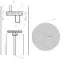
目前多片式外延技术中,最主要的问题是同时多片生长的外延层薄膜片内、片间厚度均匀性问题。常用的立式HVPE系统中,前驱物输运管道系统是由金属前驱物气体输运管道、氮化物前驱物气体输运管道、以及其间的惰性稀释(ID)气体输运管道组成的同心圆结构,一般位于反应区中心区域。在外延生长时,由于大部分氮化物前驱物气体在未达到衬底时从尾气排放口抽走,其达到衬底表面的浓度呈指数递减,并随着ID流量的增大其递减的速度增大,当单片衬底位于托盘中心时,衬底上外延层厚度出现一个圆形厚膜带,圆形厚膜带随着ID流量的增大由衬底中心向外移动,优化金属前驱物气体、氮化物前驱物气体与ID气体在反应区的流场,可解决单片外延薄膜厚度均匀性问题(见附图2)。但用这种结构生长三片衬底时(附图3),厚膜带由圆形变成环形,调节金属前驱物气体、氮化物气体与ID气体在反应区的流场,将厚膜带移动到衬底中心时,外延层厚度均匀性最好,但其均匀性也只能达到±15%左右(见附图4),远不能满足后续器件制备时的片内厚度均匀性小于±5%的要求。At present, in the multi-chip epitaxy technology, the most important problem is the uniformity of the thickness of the epitaxial layer film grown on multiple chips at the same time. In a commonly used vertical HVPE system, the precursor transportation pipeline system is a concentric circle structure composed of a metal precursor gas transportation pipeline, a nitride precursor gas transportation pipeline, and an inert dilution (ID) gas transportation pipeline in between. , generally located in the center of the reaction zone. During epitaxial growth, because most of the nitride precursor gas is drawn from the exhaust port before reaching the substrate, the concentration of the nitride precursor gas reaching the substrate surface decreases exponentially, and the decreasing speed increases with the increase of the ID flow rate. Large, when the monolithic substrate is located in the center of the tray, a circular thick film band appears on the thickness of the epitaxial layer on the substrate, and the circular thick film band moves outward from the center of the substrate with the increase of the ID flow rate, optimizing the metal precursor The flow field of gas, nitride precursor gas and ID gas in the reaction zone can solve the problem of thickness uniformity of monolithic epitaxial film (see Figure 2). However, when three substrates are grown with this structure (Fig. 3), the thick film belt changes from a circular shape to a ring shape, and the flow field of the metal precursor gas, nitride gas, and ID gas in the reaction zone is adjusted to make the thick film belt When moving to the center of the substrate, the thickness uniformity of the epitaxial layer is the best, but its uniformity can only reach about ±15% (see Figure 4), which is far from satisfying the intra-chip thickness uniformity of less than ±5% during subsequent device preparation. % requirements.
发明内容Contents of the invention
本发明的目的在于提供一种通过改进HVPE系统源气体输运装置以调控生长流场的方法,改善多片式大面积薄膜材料生长的均匀性,提高产品的产出率与源材料的利用率,降低生产成本。The purpose of the present invention is to provide a method for regulating the growth flow field by improving the source gas transportation device of the HVPE system, improve the uniformity of the growth of multi-piece large-area thin film materials, and improve the output rate of products and the utilization rate of source materials ,reduce manufacturing cost.
本发明提出的改进多片式外延材料厚度分布均匀性的氢化物气相沉积装置与方法,根据衬底基片的排列设计多套由金属前驱物气体输运管道、氮化物前驱物输运管道、以及稀释惰性气体输运管道组成的同心圆输运管道系统,根据源气体输运与扩散特性优化各管道的长度与径度配比及源气体的流量,结合衬底的旋转,使反应物前驱物气体在各衬底表面的总分布概率基本一致,从而改善多片衬底外延层薄膜的厚度均匀性。The hydride vapor deposition device and method for improving the thickness distribution uniformity of multi-chip epitaxial materials proposed by the present invention, according to the arrangement of substrates, multiple sets of metal precursor gas transportation pipelines, nitride precursor transportation pipelines, And the concentric transportation pipeline system composed of the diluted inert gas transportation pipeline, the length and diameter ratio of each pipeline and the flow rate of the source gas are optimized according to the transportation and diffusion characteristics of the source gas, combined with the rotation of the substrate, the precursor of the reactant The total distribution probability of the substance gas on the surface of each substrate is basically the same, thereby improving the thickness uniformity of the epitaxial film on multiple substrates.
本发明的通过调控源气体的输运与扩散改进衬底表面流场,用同一炉制备多片薄膜厚度分布均匀的GaN衬底的外延技术,能有效提高源材料的利用率与生产效率,实现低成本的批量生产。The present invention improves the flow field on the surface of the substrate by regulating the transport and diffusion of the source gas, and uses the same furnace to prepare multiple GaN substrates with uniform thickness distribution, which can effectively improve the utilization rate and production efficiency of the source material, and realize Low cost mass production.
一种改进多片式外延材料厚度分布均匀性的氢化物气相沉积装置,该装置为HVPE反应腔,是立式腔体结构,该装置的腔体内上部设有金属承载舟,金属承载舟顶面设有氢化物与载气入口通道,金属承载舟的外侧面设有保护性惰性气体输运管道,保护性惰性气体输运管道位于金属承载舟的外侧面与腔体内壁之间,金属承载舟的底面设有前驱物气体输运系统,前驱物气体输运系统的下方设有承载衬底的石墨托盘,承载衬底的石墨托盘的底部设有支撑托盘的石英杆;A hydride vapor deposition device for improving the thickness distribution uniformity of multi-chip epitaxial materials. The device is an HVPE reaction chamber with a vertical chamber structure. A metal carrier boat is arranged on the upper part of the cavity of the device, and the top surface of the metal carrier boat is There are inlet channels for hydride and carrier gas. The outer surface of the metal carrier boat is provided with a protective inert gas delivery pipeline. The protective inert gas delivery pipeline is located between the outer surface of the metal carrier boat and the inner wall of the cavity. The metal carrier boat A precursor gas transport system is provided on the bottom surface of the precursor gas transport system, a graphite tray for carrying the substrate is provided below the precursor gas transport system, and a quartz rod for supporting the tray is provided at the bottom of the graphite tray for carrying the substrate;
一套前驱物气体输运系统由金属前驱物气体输运管道、惰性稀释气体输运管道、氮化物前驱物输运管道组成的同心圆结构;A set of precursor gas delivery system is a concentric structure composed of metal precursor gas delivery pipelines, inert dilution gas delivery pipelines, and nitride precursor delivery pipelines;
在其中一些实施例中,所述承载衬底的石墨托盘上在生长3片衬底时,配有一套同心圆前驱物气体输运系统,前驱物气体输运系统在金属承载舟上的位置偏离金属承载舟中心,位于在承载衬底的石墨托盘上3片衬底的圆心轨迹的正上方。In some of these embodiments, when three substrates are grown on the graphite tray carrying the substrate, it is equipped with a set of concentric circle precursor gas delivery system, and the position of the precursor gas delivery system on the metal carrier boat deviates from The center of the metal carrying boat is located directly above the center track of the three substrates on the graphite tray carrying the substrates.
在其中一些实施例中,所述承载衬底的石墨托盘上生长7片衬底时,配有两套同心圆前驱物气体输运系统,同心圆前驱物气体输运系统间输入保护性惰性气体。两套同心圆前驱物气体输运系统的直径及其配比与单片系统相同,输运管道长度根据流场而改变,其中一套前驱物气体输运系统的位置在承载衬底的石墨托盘中心的正上方,另一套前驱物气体输运系统偏离金属承载舟中心位置,在承载衬底的石墨托盘上外圈6片衬底连心圆周线(托盘旋转时外圈衬底的圆心转动时的轨迹)的正上方。In some of these embodiments, when seven substrates are grown on the graphite tray carrying the substrate, two sets of concentric circle precursor gas delivery systems are equipped, and protective inert gas is input between the concentric circle precursor gas delivery systems . The diameters and ratios of the two concentric precursor gas delivery systems are the same as those of the monolithic system, and the length of the delivery pipeline changes according to the flow field. One of the precursor gas delivery systems is located on the graphite tray carrying the substrate. Just above the center, another set of precursor gas delivery system deviates from the center position of the metal carrier boat, and on the graphite tray carrying the substrate, the outer circle of 6 substrates connects the center circle line (the center of the outer circle substrate rotates when the tray rotates time trajectory) directly above.
在其中一些实施例中,所述承载衬底的石墨托盘上生长19片衬底时,配有三套同心圆前驱物气体输运系统,同心圆前驱物气体输运系统间输入保护性惰性气体。三套同心圆前驱物气体输运系统的直径及其配比与单片系统相同,输运管道长度根据流场而改变,其中一套前驱物气体输运系统的位置在承载衬底的石墨托盘的中心正上方;另一套前驱物气体输运系统偏离金属承载舟中心位置,在承载衬底的石墨托盘上中圈6片衬底连心圆周线的正上方;第三套前驱物气体输运系统偏离金属承载舟中心位置,在承载衬底的石墨托盘上外圈12片衬底连心圆周线的正上方;In some of these embodiments, when 19 substrates are grown on the graphite tray carrying the substrates, three sets of concentric precursor gas delivery systems are equipped, and protective inert gas is input between the concentric precursor gas delivery systems. The diameters and proportions of the three concentric precursor gas delivery systems are the same as those of the monolithic system, and the length of the delivery pipeline changes according to the flow field. One of the precursor gas delivery systems is located on the graphite tray carrying the substrate directly above the center of the center; another set of precursor gas delivery system deviates from the center position of the metal carrier boat, and is directly above the center-to-center circle line of six substrates on the graphite tray carrying the substrate; the third set of precursor gas delivery system The transportation system deviates from the center position of the metal carrier boat, and is directly above the center-to-center circle line of the 12 substrates on the graphite tray carrying the substrates;
在其中一些实施例中,所述承载衬底的石墨托盘上生长19片衬底时,配有七套同心圆前驱物气体输运系统,前驱物气体输运系统间输入保护性惰性气体。七套前驱物气体输运系统的直径及其配比与单片系统相同,输运管道长度根据流场而改变,其中一套前驱物气体输运系统的位置在承载衬底的石墨托盘的中心正上方;另外两套前驱物气体输运系统尺寸规格相同,位于偏离金属承载舟中心位置,在承载衬底的石墨托盘上中圈6片衬底连心圆周线的正上方,关于金属承载舟中心成中心对称;另四套前驱物气体输运系统尺寸规格相同,位于偏离金属承载舟中心位置,在承载衬底的石墨托盘上外圈12片衬底连心圆周线的正上方,关于金属承载舟中心成中心对称。In some of these embodiments, when 19 substrates are grown on the graphite tray carrying the substrates, seven sets of concentric precursor gas delivery systems are equipped, and protective inert gas is input between the precursor gas delivery systems. The diameters and proportions of the seven precursor gas delivery systems are the same as those of the monolithic system, and the length of the delivery pipeline changes according to the flow field. One of the precursor gas delivery systems is located in the center of the graphite tray carrying the substrate Directly above; the other two sets of precursor gas transport systems have the same size and specification, and are located away from the center of the metal carrier boat, directly above the center-to-center circle line of the 6 substrates on the graphite tray carrying the substrate, about the metal carrier boat The center is centrally symmetrical; the other four sets of precursor gas delivery systems have the same size and specifications, and are located away from the center of the metal carrier boat, directly above the circle line connecting the center of the 12 substrates on the graphite tray that carries the substrate. The center of the bearing boat is symmetrical to the center.
一种改进多片式外延材料厚度分布均匀性的氢化物气相沉积方法,其特征在于:A hydride vapor deposition method for improving the uniformity of thickness distribution of multi-chip epitaxial materials, characterized in that:
①、将待外延生长GaN薄膜的衬底进行表面处理,去除衬底表面污染改善衬底表面特性;①. Surface treatment is carried out on the substrate to be epitaxially grown GaN film to remove contamination on the surface of the substrate and improve the surface characteristics of the substrate;
所述表面处理技术,是指在金属有机物化学气相淀积MOCVD反应室或其他高温退火炉中采用氢气、氮气、氨气以及其他气体对衬底表面进行烘烤处理;The surface treatment technology refers to the use of hydrogen, nitrogen, ammonia and other gases to bake the substrate surface in a MOCVD reaction chamber or other high-temperature annealing furnace;
在其中一些实施例中,所述表面处理技术,是指采用氢气、氮气、氨气以及其他气体对(蓝宝石、碳化硅、硅以及氧化锌)衬底表面(GaN异质衬底表面)进行烘烤处理,温度1000~1600℃,时间1~480分钟;In some of these embodiments, the surface treatment technology refers to the use of hydrogen, nitrogen, ammonia and other gases to bake the substrate surface (sapphire, silicon carbide, silicon and zinc oxide) (GaN heterogeneous substrate surface) Baking treatment, temperature 1000-1600 ℃, time 1-480 minutes;
在其中一些实施例中,所述表面烘烤处理,可以在金属有机物化学气相淀积MOCVD反应室中处理,也可以在其他高温退火炉中进行;In some of these embodiments, the surface baking treatment can be performed in a MOCVD reaction chamber or in other high-temperature annealing furnaces;
所述衬底,是指蓝宝石衬底、碳化硅衬底、硅衬底或氧化锌衬底;The substrate refers to a sapphire substrate, a silicon carbide substrate, a silicon substrate or a zinc oxide substrate;
上述衬底表面是极性c面,或是非极性半极性晶面;The above-mentioned substrate surface is a polar c-plane, or a non-polar semi-polar crystal plane;
②、将经过表面处理的(蓝宝石、碳化硅、硅或氧化锌)衬底在MOCVD反应室中生长GaN模版,采用低温缓冲层技术加高温生长技术的两步法生长3片及以上的GaN模版,GaN薄膜厚度为2~10μm;②. Grow the GaN template on the surface-treated (sapphire, silicon carbide, silicon or zinc oxide) substrate in the MOCVD reaction chamber, and use the two-step method of low-temperature buffer layer technology and high-temperature growth technology to grow 3 or more GaN templates , the thickness of the GaN film is 2-10 μm;
在其中一些实施例中,所述低温缓冲层技术,是指但不限于低温生长GaN多晶层,缓冲层厚度为30~800nm;In some of these embodiments, the low-temperature buffer layer technology refers to but is not limited to low-temperature growth of GaN polycrystalline layers, and the thickness of the buffer layer is 30-800 nm;
③、将步骤②所获得的3片及以上的GaN模版放置于HVPE反应腔中,进行的GaN单晶材料的快速生长,调控前驱物气体输运系统的输运与扩散,通过承载衬底的石墨托盘的旋转,使生长区衬底表面的源气体以一定的配比均匀分布,制备厚度分布均匀的GaN复合衬底,GaN厚度为10~5000μm。③.
在其中一些实施例中,步骤③中所述HVPE反应腔是氢化物气相沉积装置,为立式结构,一套前驱物气体输运系统由金属前驱物气体输运管道、惰性稀释气体输运管道、氮化物前驱物输运管道组成的同心圆结构;In some of these embodiments, the HVPE reaction chamber described in
步骤③中所述通过承载衬底的石墨托盘的旋转,带动衬底的旋转,通过支撑托盘的石英杆的驱动,促使反应物前驱体气体在衬底表面的总分布概率基本一致的承载衬底的石墨托盘的转动,转动速度为5~500rpm。In
在其中一些实施例中,所述承载衬底的石墨托盘上在生长3片衬底时,配有两套规格尺寸相同的同心圆前驱物气体输运系统,前驱物气体输运系统间输入保护性惰性气体;两套前驱物气体输运系统管道的尺寸与比例参数相同,其位置偏离金属承载舟中心,位于在承载衬底的石墨托盘上3片衬底连心圆周线(托盘旋转时衬底的圆心转动时的轨迹)的正上方,两者关于金属承载舟中心成中心对称;In some of these embodiments, when three substrates are grown on the graphite tray carrying the substrate, it is equipped with two sets of concentric circular precursor gas delivery systems with the same specification and size, and the input protection between the precursor gas delivery systems Inert gas; the size and proportion parameters of the two sets of precursor gas delivery system pipelines are the same, and their positions deviate from the center of the metal carrier boat, and they are located on the graphite tray that carries the substrate. The trajectory when the center of the bottom rotates) is directly above the center of the metal carrier boat;
在其中一些实施例中,所述承载衬底的石墨托盘上在生长7片衬底时,配有三套同心圆前驱物气体输运系统,前驱物气体输运系统间输入保护性惰性气体,三套前驱物气体输运系统的直径及其配比相同,输运管道长度根据流场而改变,其中一套前驱物气体输运系统的位置在承载衬底的石墨托盘中心的正上方,另两套前驱物气体输运系统尺寸规格相同,位于偏离金属承载舟中心位置,在承载衬底的石墨托盘上外圈6片衬底连心圆周线的正上方,关于金属承载舟中心成中心对称;In some of these embodiments, when seven substrates are grown on the graphite tray carrying the substrate, three sets of concentric circular precursor gas delivery systems are equipped, and protective inert gas is input between the precursor gas delivery systems, and three The diameters and proportions of the two sets of precursor gas delivery systems are the same, and the length of the delivery pipelines changes according to the flow field. One set of precursor gas delivery systems is located directly above the center of the graphite tray carrying the substrate, and the other two The size and specification of the precursor gas delivery system are the same, and they are located away from the center of the metal carrier boat, directly above the circle line connecting the six substrates on the outer circle of the graphite tray that carries the substrate, and are symmetrical about the center of the metal carrier boat;
在其中一些实施例中,所述承载衬底的石墨托盘上在生长19片衬底时,配有五套同心圆前驱物气体输运系统,前驱物气体输运系统间输入保护性惰性气体,五套前驱物气体输运系统的直径及其配比相同,输运管道长度根据流场而改变,其中一套前驱物气体输运系统的位置在承载衬底的石墨托盘的中心正上方,另两套前驱物气体输运系统尺寸规格相同,位于偏离金属承载舟中心位置,在承载衬底的石墨托盘上中圈6片衬底连心圆周线的正上方,关于金属承载舟中心成中心对称,第四、五套前驱物气体输运系统尺寸规格相同,位于偏离金属承载舟中心位置,在承载衬底的石墨托盘上外圈12片衬底连心圆周线的正上方,关于金属承载舟中心成中心对称。In some of these embodiments, when 19 substrates are grown on the graphite tray carrying the substrate, five sets of concentric circular precursor gas delivery systems are equipped, and protective inert gas is input between the precursor gas delivery systems, The diameters and ratios of the five precursor gas delivery systems are the same, and the length of the delivery pipeline changes according to the flow field. One of the precursor gas delivery systems is located directly above the center of the graphite tray carrying the substrate, and the other The two sets of precursor gas delivery systems have the same size and specifications, and are located away from the center of the metal carrier boat, directly above the center-to-center circle line of the 6 substrates on the graphite tray carrying the substrate, and are symmetrical about the center of the metal carrier boat. , the fourth and fifth sets of precursor gas transport systems have the same size and specification, and are located away from the center of the metal carrier boat, directly above the circle line connecting the centers of the 12 substrates on the graphite tray that carries the substrate, and about the metal carrier boat The center is centrosymmetric.
在其中一些实施例中,所述调控前驱物气体输运系统的输运与扩散,是指通过调控惰性稀释(ID)气体的流量调控金属前驱物气体与含氮前驱物气体扩散到衬底表面的浓度及其配比,调控衬底表面外延材料的生长速度及厚度分布。In some of these embodiments, the regulating the transport and diffusion of the precursor gas transport system refers to regulating the diffusion of metal precursor gas and nitrogen-containing precursor gas to the substrate surface by regulating the flow rate of inert dilution (ID) gas The concentration and its ratio can regulate the growth rate and thickness distribution of the epitaxial material on the substrate surface.
在其中一些实施例中,所述调控前驱物气体输运系统的输运与扩散,是指调节前驱物源气喷射口到衬底的距离,调控衬底表面外延材料的生长速度及厚度分布,并提高源材料的利用率。In some of these embodiments, the regulating the transport and diffusion of the precursor gas transport system refers to adjusting the distance from the precursor source gas injection port to the substrate, and regulating the growth rate and thickness distribution of the epitaxial material on the substrate surface, And improve the utilization of source materials.
采用本发明的一种通过调控前驱物气体流场的改进多片外延材料厚膜分布均匀性的方法,在同一炉外延生长3片GaN复合衬底,3片薄膜厚度分布均匀性变化控制在±5%以内,晶片间平均厚度差在3%以内,如图8所示。Using a method of the present invention to improve the distribution uniformity of multi-piece epitaxial material thick films by regulating the gas flow field of the precursor, three GaN composite substrates are epitaxially grown in the same furnace, and the thickness distribution uniformity of the three films is controlled within ± Within 5%, the average thickness difference between wafers is within 3%, as shown in Figure 8.
采用本发明方法制备的多片氮化镓复合衬底,表面光亮无裂纹;工艺简单,易于控制,重复可靠性高;一炉可以同时生长多片,生产效率以及源材料的利用率高,能有效降低生产成本,是一种经济实用性强、可实现工业化量产的GaN衬底制备技术。The multi-piece gallium nitride composite substrate prepared by the method of the present invention has a bright surface without cracks; the process is simple, easy to control, and has high repeat reliability; one furnace can grow multiple pieces at the same time, the production efficiency and the utilization rate of source materials are high, and the production efficiency and source material utilization rate are high. Effectively reducing production costs, it is an economical and practical GaN substrate preparation technology that can realize industrial mass production.
附图说明Description of drawings
图1所示为本发明的HVPE立式结构系统中的前驱物输运管道系统结构组成及气路的截面示意图;Fig. 1 shows the cross-sectional schematic diagram of the composition of the precursor transport pipeline system and the gas path in the HVPE vertical structure system of the present invention;
图2所示为采用传统单片立式HVPE结构系统在不同ID流量下制备的50μmGaN薄膜材料厚度分布图像,其中ID流量分别为:7600sccm(图2a),12000sccm(图2b),15000sccm(图2c),图2d为优化ID流量制备的厚度均匀性为±1.8%的GaN薄膜厚度分布图像;Figure 2 shows the thickness distribution images of 50 μm GaN thin film materials prepared by traditional monolithic vertical HVPE structure system under different ID flow rates, where the ID flow rates are: 7600 sccm (Figure 2a), 12000 sccm (Figure 2b), 15000 sccm (Figure 2c) ), Fig. 2d is the thickness distribution image of GaN film with thickness uniformity of ±1.8% prepared by optimizing ID flow;
图3所示为传统的多片立式HVPE系统结构截面示意图与承载3片衬底的托盘示意图;Figure 3 shows a schematic cross-sectional view of a traditional multi-piece vertical HVPE system structure and a schematic diagram of a tray carrying three substrates;
图4所示为采用传统多片立式HVPE系统生长中采用不同ID流量时制备的GaN薄膜厚度分布图像,其中ID流量分别为7600sccm(图4a),12000sccm(图4b),15000sccm(图4c);Figure 4 shows the thickness distribution images of GaN films prepared by using different ID flow rates in the growth of a traditional multi-chip vertical HVPE system, where the ID flow rates are 7600 sccm (Figure 4a), 12000 sccm (Figure 4b), and 15000 sccm (Figure 4c) ;
图5所示为本发明的新型3片立式HVPE结构截面示意图与承载3片衬底的托盘示意图;Figure 5 shows a schematic cross-sectional view of a novel 3-piece vertical HVPE structure of the present invention and a schematic diagram of a pallet carrying 3 substrates;
图6所示为本发明的新型7片立式HVPE结构截面示意图与承载7片衬底的托盘示意图;Fig. 6 is a schematic cross-sectional view of a novel 7-piece vertical HVPE structure of the present invention and a schematic diagram of a tray carrying 7 substrates;
图7所示为本发明的新型19片立式HVPE结构截面示意图与承载19片衬底的托盘示意图;Fig. 7 is a schematic cross-sectional view of a novel 19-piece vertical HVPE structure of the present invention and a schematic diagram of a tray carrying 19 substrates;
图8所示为本发明的采用新型3片立式HVPE系统一炉同时生长3片时外延层厚度均匀性为±4.8%的衬底厚度分布图及实验与模拟厚度变化曲线;Fig. 8 shows the substrate thickness distribution diagram and the experimental and simulated thickness variation curves of ± 4.8% when the epitaxial layer thickness uniformity is ± 4.8% when the novel 3-piece vertical HVPE system is used in one furnace to grow 3 pieces at the same time;
附图标记说明:Explanation of reference signs:
1:金属承载舟,2:承载衬底的石墨托盘,3:支撑托盘的石英杆,4:氢化物与载气入口通道,51:金属前驱物气体输运管道,52:惰性稀释气体输运管道,53:氮化物前驱物输运管道,5:前驱物气体输运系统,6:保护性惰性气体输运管道,7:多片式衬底排列的石墨托盘正面。1: metal carrier boat, 2: graphite tray for substrate, 3: quartz rod for supporting tray, 4: hydride and carrier gas inlet channel, 51: metal precursor gas delivery pipeline, 52: inert dilution gas delivery Pipeline, 53: nitride precursor transportation pipeline, 5: precursor gas transportation system, 6: protective inert gas transportation pipeline, 7: front of graphite tray with multi-chip substrate arrangement.
具体实施方式Detailed ways
为能进一步了解本发明的特征、技术手段以及所达到的具体目的、功能,解析本发明的优点与精神,藉由以下实施例对本发明做进一步的阐述。In order to further understand the characteristics, technical means, and achieved specific objectives and functions of the present invention, and to analyze the advantages and spirit of the present invention, the present invention is further described by the following examples.
本发明的一种改进多片式外延材料厚度分布均匀性的氢化物气相沉积装置为HVPE反应腔,是立式腔体结构,该装置的腔体内上部设有金属承载舟1(镓舟),金属承载舟1顶面设有氢化物与载气入口通道4,金属承载舟1的外侧面设有保护性惰性气体输运管道6,保护性惰性气体输运管道6位于金属承载舟1的外侧面与腔体内壁之间,金属承载舟1的底面设有前驱物气体输运系统5(前驱物气体输运管道同心圆结构系统),前驱物气体输运系统5的下方设有承载衬底的石墨托盘2,承载衬底的石墨托盘2的底部设有支撑托盘的石英杆3。A hydride vapor deposition device for improving the thickness distribution uniformity of multi-chip epitaxial materials in the present invention is a HVPE reaction chamber, which is a vertical chamber structure, and the upper part of the chamber is equipped with a metal carrier boat 1 (gallium boat), The top surface of the metal carrier boat 1 is provided with a hydride and carrier gas inlet channel 4, and the outer surface of the metal carrier boat 1 is provided with a protective inert
一套前驱物气体输运系统5(前驱物气体输运管道同心圆结构系统)是由金属前驱物气体输运管道51、惰性稀释气体输运管道52(ID输运管道,INNERDILUTION)、氮化物前驱物输运管道53组成的同心圆结构。A set of precursor gas transportation system 5 (concentric structure system of precursor gas transportation pipeline) is composed of metal precursor
本发明的一种通过调控前驱物源气体的输运与扩散改进衬底表面流场,同一炉制备多片薄膜厚度分布均匀的GaN衬底,能有效提高源材料的利用率与生产效率,实现低成本批量生产的外延技术,工艺如下:The method of the present invention improves the flow field on the surface of the substrate by regulating the transport and diffusion of the precursor source gas, and prepares multiple GaN substrates with uniform film thickness distribution in the same furnace, which can effectively improve the utilization rate and production efficiency of source materials, and realize Epitaxial technology for low-cost mass production, the process is as follows:
通过改进立式HVPE反应腔中前驱物气体输运系统5管道结构,根据衬底基片的排列设计多套由金属前驱物气体输运管道51、惰性稀释气体输运管道52(ID输运管道,INNER DILUTION)、氮化物前驱物输运管道53组成的同心圆输运管道系统,优化衬底的旋转,使反应物前驱物气体在衬底表面的总分布概率基本一致,从而调节多片衬底外延层薄膜的厚度均匀性;By improving the pipeline structure of the precursor gas transportation system 5 in the vertical HVPE reaction chamber, multiple sets of metal precursor
根据源气体的输运与扩散特性优化设计同心圆输运管道系统的长度,延长反应前驱物在衬底的停留时间,减少含氮前驱物从尾气输出口的排除量,同时在同心圆前驱物气体输运系统5间通入惰性气体,抑制副产物的沉积,延长设备的持续运行时间提高生产效率,促进含氮前驱物向衬底表面的扩散,提高其在衬底表面的浓度配比,从而调控生长所需流场,提高源材料的利用率。According to the transportation and diffusion characteristics of the source gas, the length of the concentric transportation pipeline system is optimized to prolong the residence time of the reaction precursor on the substrate, reduce the exhaustion of the nitrogen-containing precursor from the exhaust outlet, and at the same time The inert gas is introduced into the gas transportation system 5 to suppress the deposition of by-products, prolong the continuous operation time of the equipment, improve production efficiency, promote the diffusion of nitrogen-containing precursors to the substrate surface, and increase its concentration ratio on the substrate surface. In this way, the flow field required for growth can be regulated, and the utilization rate of source materials can be improved.
上述衬底包括但不局限于蓝宝石衬底,可以是碳化硅、硅以及氧化锌或其他材料衬底,衬底表面可以是极性c面,也可以是其他非极性、半极性晶面;蓝宝石衬底直径可以是1英寸、2英寸、6英寸、8英寸以及其他尺寸衬底。The above-mentioned substrates include but are not limited to sapphire substrates, which can be silicon carbide, silicon, zinc oxide or other material substrates, and the substrate surface can be polar c-plane, or other non-polar and semi-polar crystal planes ; The diameter of the sapphire substrate can be 1 inch, 2 inches, 6 inches, 8 inches and other size substrates.
在其中一些实施例中,立式HVPE反应腔中,配有一套由金属前驱物气体输运管道51、惰性稀释气体输运管道52(ID输运管道,INNER DILUTION)、氮化物前驱物输运管道53组成的同心圆结构前驱物气体输运系统5,置于偏离金属承载舟1(镓舟)中心区域30~40mm、与承载衬底的石墨托盘2上衬底放置位置的圆心相对应的正上方,如附图5所示,或者配有两套尺寸规格全同的同心圆结构前驱物气体输运系统5,关于金属承载舟1(镓舟)中心成中心对称,置于偏离金属承载舟1(镓舟)中心区域30~40mm、与承载衬底的石墨托盘2上衬底放置位置的中心相对应的正上方,用于制备3片2英寸GaN衬底。In some of these embodiments, the vertical HVPE reaction chamber is equipped with a set of metal precursor
在其中一些实施例中,立式HVPE反应腔中,同心圆结构前驱物气体输运系统5有两套,前驱物气体输运系统5间输入保护性惰性气体,用于生长7片2英寸GaN衬底。输运管道的长度可以根据流场而改变,其中一套前驱物气体输运系统5的位置在承载衬底的石墨托盘2中心的正上方,另一套前驱物气体输运系统5偏离金属承载舟1中心区域50~60mm,在承载衬底的石墨托盘2上外圈6片衬底连心圆周线(托盘旋转时外圈衬底的圆心转动时的轨迹)的正上方,如附图6所示;承载衬底的石墨托盘2当排列7片衬底时,可通过多片式衬底排列的石墨托盘正面7观察其排列状态。In some of these embodiments, in the vertical HVPE reaction chamber, there are two sets of concentric circular structure precursor gas delivery systems 5, and protective inert gas is input between the precursor gas delivery systems 5 for growing seven pieces of 2-inch GaN substrate. The length of the transport pipeline can be changed according to the flow field. One set of precursor gas transport system 5 is located directly above the center of the
在其中一些实施例中,立式HVPE反应腔中,同心圆结构前驱物气体输运系统5有三套,前驱物气体输运系统5间输入保护性惰性气体,用于生长7片2英寸GaN衬底。输运管道的长度可以根据流场而改变,其中一套前驱物气体输运系统5的位置在承载衬底的石墨托盘2中心的正上方,另两套前驱物气体输运系统5尺寸规格相同,位于偏离金属承载舟1中心区域50~60mm,在承载衬底的石墨托盘2上外圈6片衬底连心圆周线的正上方,关于金属承载舟1中心成中心对称。In some of these embodiments, in the vertical HVPE reaction chamber, there are three sets of concentric circular structure precursor gas delivery systems 5, and protective inert gas is input between the precursor gas delivery systems 5 for growing seven 2-inch GaN substrates. end. The length of the transport pipeline can be changed according to the flow field. One set of precursor gas transport system 5 is located directly above the center of the
在其中一些实施例中,立式HVPE反应腔中,同心圆结构前驱物气体输运系统5为三套,前驱物气体输运系统5间输入保护性惰性气体。输运管道长度可以根据流场而改变,其中一套前驱物气体输运系统5的位置在承载衬底的石墨托盘2中心的正上方,另一套前驱物气体输运系统5偏离金属承载舟1中心区域50~60mm,在承载衬底的石墨托盘2上中圈6片衬底连心圆周线的正上方,第三套前驱物气体输运系统5偏离金属承载舟1中心区域80~90mm,在承载衬底的石墨托盘2上外圈12片衬底连心圆周线的正上方,用于生长19片2英寸GaN衬底,如附图7所示。In some of these embodiments, in the vertical HVPE reaction chamber, there are three concentric circular precursor gas delivery systems 5 , and protective inert gas is input between the precursor gas delivery systems 5 . The length of the transport pipeline can be changed according to the flow field. One set of precursor gas transport system 5 is located directly above the center of the
在其中一些实施例中,立式HVPE反应腔中,同心圆结构前驱物气体输运系统5为五套,前驱物气体输运系统5间输入保护性惰性气体。输运管道长度可以根据流场而改变,其中一套前驱物气体输运系统5的位置在承载衬底的石墨托盘2中心的正上方,另两套前驱物气体输运系统5尺寸规格相同,位于偏离金属承载舟1中心区域50~60mm,在承载衬底的石墨托盘2上中圈6片衬底连心圆周线的正上方,关于金属承载舟1中心成中心对称,还有两套全同前驱物气体输运系统5偏离金属承载舟1中心区域80~90mm,在承载衬底的石墨托盘2上外圈12片衬底连心圆周线的正上方,关于金属承载舟1中心成中心对称,用于生长19片2英寸GaN衬底。In some of these embodiments, in the vertical HVPE reaction chamber, there are five concentric circular precursor gas delivery systems 5 , and protective inert gas is input between the precursor gas delivery systems 5 . The length of the transport pipeline can be changed according to the flow field. One set of precursor gas transport system 5 is located directly above the center of the
在其中一些实施例中,立式HVPE反应腔中,同心圆结构前驱物气体输运系统5为七套,前驱物气体输运系统5间输入保护性惰性气体。输运管道长度可以根据流场而改变,其中一套前驱物气体输运系统5的位置在承载衬底的石墨托盘2中心的正上方,另两套前驱物气体输运系统5尺寸规格相同,位于偏离金属承载舟1中心区域50~60mm,在承载衬底的石墨托盘2上中圈6片衬底连心圆周线的正上方,关于金属承载舟1(镓舟)中心成中心对称,还有四套尺寸规格全同的前驱物气体输运系统5偏离金属承载舟1中心区域80~90mm,在承载衬底的石墨托盘2上外圈12片衬底连心圆周线的正上方,关于金属承载舟1中心成中心对称,用于生长19片2英寸GaN衬底。In some of these embodiments, in the vertical HVPE reaction chamber, there are seven sets of concentric circular precursor gas delivery systems 5 , and protective inert gas is input between the precursor gas delivery systems 5 . The length of the transport pipeline can be changed according to the flow field. One set of precursor gas transport system 5 is located directly above the center of the
在其中一些实施例中,所述立式HVPE反应腔中,承载衬底的石墨托盘2的直径为120~450mm,用于承载多片待外延衬底。承载衬底的石墨托盘2由支撑托盘的石英杆3驱动旋转,转速为5~500rpm,使反应物前驱体气体在衬底表面的总分布概率基本一致,从而调节多片衬底外延层薄膜的厚度均匀性。In some of the embodiments, in the vertical HVPE reaction chamber, the
在其中一些实施例中,前驱物气体输运系统5调控前驱物气体的输运与扩散,调节ID的流量,以调控金属前驱物气体与含氮前驱物气体扩散到衬底表面的浓度及其配比,调控衬底表面外延材料的生长速度及厚度分布,ID流量为2000~30000sccm,最佳ID流量为5000~20000sccm。In some of these embodiments, the precursor gas transport system 5 regulates the transport and diffusion of the precursor gas, and adjusts the flow rate of the ID, so as to control the concentration and concentration of the metal precursor gas and nitrogen-containing precursor gas diffused to the substrate surface. Ratio, adjust the growth rate and thickness distribution of the epitaxial material on the substrate surface, the ID flow rate is 2000-30000 sccm, and the optimal ID flow rate is 5000-20000 sccm.
结合图5~图7,详细给出以下三个实施例。The following three embodiments are given in detail with reference to FIG. 5 to FIG. 7 .
实施例一的技术方案:The technical scheme of embodiment one:
1、蓝宝石衬底表面预处理:将商业购置的可直接外延的蓝宝石衬底置于MOCVD设备中,通入保护性气氛,包括但不限于氮气、氨气、惰性气体、氢气等气体,温度1000~1200℃,保温10~120分钟;1. Surface pretreatment of sapphire substrate: Place a commercially purchased sapphire substrate that can be directly epitaxy in MOCVD equipment, and pass it into a protective atmosphere, including but not limited to nitrogen, ammonia, inert gas, hydrogen and other gases, at a temperature of 1000 ~1200℃, keep warm for 10~120 minutes;
2、MOCVD模版制备:蓝宝石衬底表面预处理后,将温度降低到550~600℃,生长低温缓冲层,厚度为30~60nm。低温缓冲层有利于释放异质衬底外延产生的应力。然后升温至900~1100℃生长高温GaN/蓝宝石复合衬底,GaN厚度为3~6μm;2. Preparation of MOCVD template: After the surface of the sapphire substrate is pretreated, the temperature is lowered to 550-600° C., and a low-temperature buffer layer is grown with a thickness of 30-60 nm. The low-temperature buffer layer is conducive to releasing the stress generated by the epitaxy of the heterogeneous substrate. Then raise the temperature to 900-1100°C to grow a high-temperature GaN/sapphire composite substrate with a GaN thickness of 3-6 μm;
3、HVPE二次外延高质量薄膜:把3片MOCVD生长的GaN/蓝宝石模版按附图5中的多片式衬底排列的石墨托盘正面7(高强石墨托盘)的位置摆放,在新型三片立式HVPE中二次外延生长高质量的厚度分布均匀的GaN单晶层,见附图5。如图所示,其中,由金属前驱物气体输运管道51、氮化物前驱物气体输运管道53,以及它们之间的惰性稀释气体输运管道52(ID管道)组成的前驱物输运管道系统5,其位置与承载衬底的石墨托盘2上衬底的位置相对应,偏离金属承载舟1中心区域30~40mm,在承载衬底的石墨托盘2上3片衬底连心圆周线的正上方。首先,对MOCVD模版采用氨气、惰性气体、氢气和氯化氢等气体进行表面处理,去除表面有机物和氧化层;然后,调节金属前驱物气体输运管道51、氮化物前驱物气体输运管道53、其间的惰性稀释气体输运管道52(ID管道),以及保护性惰性气体的流量高温生长GaN单晶层薄膜,高温生长温度为1000~1100℃,V/III比(即氮化物前驱物气体与金属前驱物气体流量的比)为10~100:1,衬底的旋转速度为10~200rpm。由于外围惰性保护性气体的阻碍作用,减少了NH3在输运过程中就从尾气输出口的流失,达到衬底表面的NH3浓度增加,其从衬底表面边沿向内递减速度减缓,外延薄膜的生长速度与均匀性都大大提高,同时,由于输运管道系统在3片衬底连心圆周线的正上方,有效缓减了其在反应区中心时在3片衬底上出现的环形厚膜带现象,三片位置上的片内薄膜厚度均匀性可达到±5%以内,3片衬底片间外延层平均厚度差在3%以内。3. HVPE secondary epitaxial high-quality thin film: place 3 pieces of GaN/sapphire templates grown by MOCVD according to the position of the front 7 (high-strength graphite tray) of the graphite tray arranged with multi-chip substrates in Figure 5, in the new three A high-quality GaN single crystal layer with uniform thickness distribution is grown by secondary epitaxy in the vertical HVPE, as shown in Figure 5. As shown in the figure, among them, the precursor transport pipeline consisting of a metal precursor
实施例二的技术方案:The technical scheme of embodiment two:
1、蓝宝石衬底表面预处理:将商业购置的可直接外延的蓝宝石衬底置于MOCVD设备中,通入保护性气氛,包括但不限于氧气、氮气、氨气、惰性气体、氢气等气体,温度1000~1200℃,保温10~120分钟;1. Surface pretreatment of sapphire substrate: Place a commercially purchased sapphire substrate that can be directly epitaxy in MOCVD equipment, and pass it into a protective atmosphere, including but not limited to oxygen, nitrogen, ammonia, inert gas, hydrogen and other gases, Temperature 1000~1200℃, keep warm for 10~120 minutes;
2、MOCVD模版制备:蓝宝石衬底表面表面预处理后,将温度降低到550~600℃,生长低温缓冲层,厚度为30~60nm。低温缓冲层有利于释放异质衬底外延产生的应力。然后升温至900~1100℃生长高温GaN/蓝宝石模版,GaN厚度为3~6μm;2. Preparation of MOCVD template: After the surface of the sapphire substrate is pretreated, the temperature is lowered to 550-600° C., and a low-temperature buffer layer is grown with a thickness of 30-60 nm. The low-temperature buffer layer is conducive to releasing the stress generated by the epitaxy of the heterogeneous substrate. Then raise the temperature to 900-1100°C to grow high-temperature GaN/sapphire template, the thickness of GaN is 3-6μm;
3、HVPE二次外延高质量薄膜:把7片MOCVD生长的GaN/蓝宝石模版按附图6中的多片式衬底排列的石墨托盘正面7(高强石墨托盘)的位置摆放,在改进的7片立式HVPE中二次外延生长高质量的厚度分布均匀的GaN单晶层,见附图6。改进的7片立式HVPE系统配有两套同心圆前驱物气体输运系统5,前驱物气体输运系统5间输入保护性惰性气体。两套同心圆前驱物气体输运系统5的直径及其配比与传统的单片立式HVPE系统相同,输运管道长度可以根据流场而改变,其中一套前驱物气体输运系统5的位置在承载衬底的石墨托盘2的中心正上方,另一套前驱物气体输运系统5偏离金属承载舟1中心位置,在承载衬底的石墨托盘2上外圈6片衬底连心圆周线的正上方。对MOCVD模版进行表面处理后,根据实施例一的方法调节ID流量调控氮化物前驱物气体与金属前驱物气体在输运过程中的扩散,优化两套输运管道的长度,以及衬底的旋转速度,转速为50~200rpm,调节反应物前驱体气体达到衬底表面的总分布概率,改进多片衬底外延层薄膜的厚度均匀性。3. HVPE secondary epitaxial high-quality thin film: put 7 pieces of GaN/sapphire templates grown by MOCVD according to the position of the graphite tray front 7 (high-strength graphite tray) arranged with multi-chip substrates in Figure 6, in the improved High-quality GaN single crystal layers with uniform thickness distribution were grown by secondary epitaxial growth in 7 pieces of vertical HVPE, see Figure 6. The improved 7-piece vertical HVPE system is equipped with two sets of concentric precursor gas delivery systems 5 , and protective inert gas is input between the precursor gas delivery systems 5 . The diameters and proportions of the two sets of concentric precursor gas delivery systems 5 are the same as those of the traditional monolithic vertical HVPE system, and the length of the delivery pipelines can be changed according to the flow field. One set of precursor gas delivery systems 5 The position is directly above the center of the
实施例三的技术方案:The technical scheme of embodiment three:
1、蓝宝石衬底表面预处理:将商业购置的可直接外延的蓝宝石衬底置于MOCVD设备中,通入保护性气氛,包括但不限于氧气、氮气、氨气、惰性气体、氢气和氯化氢等气体,温度1000~1200℃,保温10~120分钟;1. Surface pretreatment of sapphire substrate: Place a commercially purchased sapphire substrate that can be directly epitaxy in MOCVD equipment, and pass it into a protective atmosphere, including but not limited to oxygen, nitrogen, ammonia, inert gas, hydrogen and hydrogen chloride, etc. Gas, temperature 1000~1200℃, keep warm for 10~120 minutes;
2、MOCVD模版制备:蓝宝石衬底表面表面预处理后,将温度降低到550~600℃,生长低温缓冲层,厚度为30~60nm。低温缓冲层有利于释放异质衬底外延产生的应力。然后升温至900~1100℃生长高温GaN/蓝宝石模版,GaN厚度为3~6μm;2. Preparation of MOCVD template: After the surface of the sapphire substrate is pretreated, the temperature is lowered to 550-600° C., and a low-temperature buffer layer is grown with a thickness of 30-60 nm. The low-temperature buffer layer is conducive to releasing the stress generated by the epitaxy of the heterogeneous substrate. Then raise the temperature to 900-1100°C to grow high-temperature GaN/sapphire template, the thickness of GaN is 3-6μm;
3、HVPE二次外延高质量薄膜:把19片MOCVD生长的GaN/蓝宝石模版按附图7中的多片式衬底排列的石墨托盘正面7(高强石墨托盘)的位置摆放,在改进的19片立式HVPE中二次外延生长高质量的厚度分布均匀的GaN单晶层,见附图7。改进的19片立式HVPE系统配有三套同心圆前驱物气体输运系统5,前驱物气体输运系统5间输入保护性惰性气体。三套同心圆前驱物气体输运系统5的直径及其配比与传统的单片立式HVPE系统相同,输运管道长度可以根据流场而改变,其中一套前驱物气体输运系统5的位置在承载衬底的石墨托盘2的中心正上方,另一套前驱物气体输运系统5偏离金属承载舟1中心位置,在承载衬底的石墨托盘2上的中圈6片衬底连心圆周线的正上方,第三套前驱物气体输运系统5偏离金属承载舟1中心位置,在承载衬底的石墨托盘2上的外圈12片衬底连心圆周线的正上方。对MOCVD模版进行表面处理后,根据实施例一的方法调节ID流量调控氮化物前驱物气体与金属前驱物气体在输运过程中的扩散,优化三套输运管道的长度及其比例,以及衬底的旋转速度,转速为50~200rpm,调节反应物前驱体气体达到衬底表面的总分布概率,改进多片衬底外延层薄膜的厚度均匀性。3. HVPE secondary epitaxial high-quality film: place 19 MOCVD-grown GaN/sapphire templates at the position of the front 7 (high-strength graphite tray) of the graphite tray arranged on the multi-chip substrate in Figure 7, in the improved High-quality GaN single crystal layers with uniform thickness distribution were grown by secondary epitaxial growth in 19 pieces of vertical HVPE, see Figure 7. The improved 19-piece vertical HVPE system is equipped with three sets of concentric precursor gas delivery systems 5 , and protective inert gas is input between the precursor gas delivery systems 5 . The diameters and ratios of the three sets of concentric precursor gas delivery systems 5 are the same as those of the traditional monolithic vertical HVPE system, and the length of the delivery pipeline can be changed according to the flow field. One set of precursor gas delivery systems 5 The position is directly above the center of the
上述三个实施例只是本发明的举例,但依照本发明原理,这还可以衍生出其它各种方案,包括将这几种方案结合的各种方案。其中只要涉及采用多套前驱物气体输运系统(前驱物气体输运管道同心圆结构系统),通过改进源气体输运管道的尺寸及配比,利用调节ID流量调控前驱物气体的输运与扩散,调节反应物前驱体气体达到衬底表面的总分布概率,而改进多片衬底外延层薄膜的厚度均匀性的方法都包含在本发明范围。The above three embodiments are only examples of the present invention, but according to the principles of the present invention, various other solutions can also be derived, including various solutions combining these several solutions. As long as it involves the use of multiple sets of precursor gas transport systems (precursor gas transport pipeline concentric circle structure system), by improving the size and ratio of source gas transport pipelines, adjusting the ID flow rate to control the transport of precursor gases and Diffusion, adjusting the total distribution probability of the reactant precursor gas reaching the substrate surface, and improving the thickness uniformity of the multi-piece substrate epitaxial layer film are all included in the scope of the present invention.
本发明有以下几个方面的优点:The present invention has the following advantages:
1、采用多套输运管道系统,优化管道的长度配比,调控源气体在衬底表面的分布概率,从而改进同一炉生长多片薄膜的片内厚度分布均匀性与片间厚度均匀性,可得到2英寸及以上大尺寸的厚度分布均匀的复合衬底,结合采用激光剥离等技术得到厚度均匀的自支撑GaN衬底,可用于制备高性能的半导体光/微电子器件;1. Adopt multiple sets of transportation pipeline systems, optimize the length ratio of pipelines, and adjust the distribution probability of source gas on the substrate surface, so as to improve the uniformity of intra-chip thickness distribution and inter-chip thickness uniformity of multiple films grown in the same furnace. Composite substrates with large size of 2 inches and above with uniform thickness distribution can be obtained, combined with laser lift-off and other technologies to obtain self-supporting GaN substrates with uniform thickness, which can be used to prepare high-performance semiconductor optical/microelectronic devices;
2、设备简单,工艺稳定重复性好,一炉生长多片不但可提高源材料的利用率,同时产品产出率的大幅提高,可有效地降低成本,适合于工业化批量生产。2. The equipment is simple, the process is stable and repeatable. Growing multiple slices in one furnace can not only increase the utilization rate of source materials, but also greatly increase the product output rate, which can effectively reduce costs and is suitable for industrialized mass production.
本发明公开了一种通过改进立式HVPE系统源气体流场,改善大面积多片式GaN薄膜材料生长均匀性的方法。该方法是通过改进多片HVPE系统的源气体输运管道系统,即根据多片衬底基片的排列设计由金属前驱物气体输运管道51,惰性稀释气体输运管道52,氮化物前驱物输运管道53组成的多套同心圆前驱物气体输运系统5,优化其尺寸及其比例以调控金属前驱物气体与含氮前驱物气体扩散到衬底表面的浓度及其配比,使反应前驱物气体在衬底表面的总分布概率基本一致,从而调节多片衬底外延层薄膜的厚度均匀性,提高源材料的利用率。本发明是一种经济实用性强适合于工业化量产的GaN制备技术,工艺简单易于控制,一炉同时生长多片,可低成本大批量制备用于同质外延的GaN自支撑衬底,满足高光电性能的光/微电子器件的要求。The invention discloses a method for improving the growth uniformity of large-area multi-chip GaN film materials by improving the source gas flow field of a vertical HVPE system. The method is by improving the source gas delivery pipeline system of the multi-chip HVPE system, that is, the metal precursor
以上所述实施例仅表达了本发明的几种实施方式,其描述较为具体和详细,但并不能因此而理解为对本发明专利范围的限制。应当指出的是,对于本领域的普通技术人员来说,在不脱离本发明构思的前提下所做出的若干替换、变化和修改的技术方案,均属于本发明的保护范围。因此,本发明专利的保护范围应以所附权利要求为准。The above-mentioned embodiments only express several implementation modes of the present invention, and the description thereof is relatively specific and detailed, but should not be construed as limiting the patent scope of the present invention. It should be noted that, for those skilled in the art, several replacements, changes and modified technical solutions without departing from the concept of the present invention all belong to the protection scope of the present invention. Therefore, the protection scope of the patent for the present invention should be based on the appended claims.
Claims (9)
Priority Applications (1)
| Application Number | Priority Date | Filing Date | Title |
|---|---|---|---|
| CN201310394554.XACN103456593B (en) | 2013-09-02 | 2013-09-02 | A kind of hydride vapor phase epitaxy apparatus and method improving multiple-piece epitaxial material thickness distributing homogeneity |
Applications Claiming Priority (1)
| Application Number | Priority Date | Filing Date | Title |
|---|---|---|---|
| CN201310394554.XACN103456593B (en) | 2013-09-02 | 2013-09-02 | A kind of hydride vapor phase epitaxy apparatus and method improving multiple-piece epitaxial material thickness distributing homogeneity |
Publications (2)
| Publication Number | Publication Date |
|---|---|
| CN103456593Atrue CN103456593A (en) | 2013-12-18 |
| CN103456593B CN103456593B (en) | 2016-02-10 |
Family
ID=49738846
Family Applications (1)
| Application Number | Title | Priority Date | Filing Date |
|---|---|---|---|
| CN201310394554.XAExpired - Fee RelatedCN103456593B (en) | 2013-09-02 | 2013-09-02 | A kind of hydride vapor phase epitaxy apparatus and method improving multiple-piece epitaxial material thickness distributing homogeneity |
Country Status (1)
| Country | Link |
|---|---|
| CN (1) | CN103456593B (en) |
Cited By (17)
| Publication number | Priority date | Publication date | Assignee | Title |
|---|---|---|---|---|
| CN105154969A (en)* | 2015-10-19 | 2015-12-16 | 中国电子科技集团公司第四十六研究所 | Single-crystal furnace cavity for improving uniformity of nitride grown by HVPE method |
| CN105917035A (en)* | 2014-01-17 | 2016-08-31 | 三菱化学株式会社 | GaN substrate, method of manufacturing GaN substrate, method of manufacturing GaN crystal, and method of manufacturing semiconductor device |
| CN106191989A (en)* | 2016-07-30 | 2016-12-07 | 东莞市中镓半导体科技有限公司 | A gallium boat reactor for HVPE equipment |
| CN107012502A (en)* | 2017-06-01 | 2017-08-04 | 镓特半导体科技(上海)有限公司 | HVPE charge delivery mechanisms, reaction chamber and HVPE equipment |
| CN107012505A (en)* | 2017-06-01 | 2017-08-04 | 镓特半导体科技(上海)有限公司 | HVPE charge delivery mechanisms, reaction chamber and HVPE equipment |
| CN107190311A (en)* | 2017-06-01 | 2017-09-22 | 镓特半导体科技(上海)有限公司 | HVPE charge delivery mechanisms, reaction chamber and HVPE equipment |
| CN107190312A (en)* | 2017-06-01 | 2017-09-22 | 镓特半导体科技(上海)有限公司 | HVPE charge delivery mechanisms, reaction chamber and HVPE equipment |
| CN107267960A (en)* | 2017-06-01 | 2017-10-20 | 镓特半导体科技(上海)有限公司 | HVPE charge delivery mechanisms, reaction chamber and HVPE equipment |
| CN109321896A (en)* | 2017-07-31 | 2019-02-12 | 北京北方华创微电子装备有限公司 | A kind of atomic layer deposition system |
| CN109585265A (en)* | 2017-09-28 | 2019-04-05 | 株式会社国际电气 | Manufacturing method, substrate processing device, the recording medium of semiconductor devices |
| CN109797375A (en)* | 2018-12-29 | 2019-05-24 | 晶能光电(江西)有限公司 | The ameliorative way of silicon substrate epitaxial wafer the thickness uniformity |
| US10475887B2 (en) | 2013-08-08 | 2019-11-12 | Mitsubishi Chemical Corporation | Self-standing GaN substrate, GaN crystal, method for producing GaN single crystal, and method for producing semiconductor device |
| CN111304741A (en)* | 2020-04-22 | 2020-06-19 | 中国工程物理研究院总体工程研究所 | GaN crystal transfer tray device based on HVPE process and transfer method |
| CN112262463A (en)* | 2018-06-07 | 2021-01-22 | 斯兰纳Uv科技有限公司 | Method and material deposition system for forming semiconductor layers |
| JP2021034675A (en)* | 2019-08-29 | 2021-03-01 | 漢民科技股▲分▼有限公司 | Gas phase film deposition device |
| CN114197037A (en)* | 2021-12-17 | 2022-03-18 | 东莞市中镓半导体科技有限公司 | Vapor phase epitaxial growth device |
| CN115747959A (en)* | 2022-11-02 | 2023-03-07 | 华灿光电(苏州)有限公司 | Chamber cover and metal organic chemical vapor deposition equipment |
Citations (5)
| Publication number | Priority date | Publication date | Assignee | Title |
|---|---|---|---|---|
| WO2003048414A1 (en)* | 2001-12-04 | 2003-06-12 | Primaxx, Inc. | Chemical vapor deposition reactor |
| CN1681088A (en)* | 2005-02-02 | 2005-10-12 | 南京大学 | A Coaxial Intake Method for Obtaining a Uniform Wide Bandgap Semiconductor Thin Film |
| CN102465333A (en)* | 2010-11-18 | 2012-05-23 | 南京大学 | Vertical hydride vapor phase epitaxial growth system |
| CN102828239A (en)* | 2012-08-24 | 2012-12-19 | 东莞市中镓半导体科技有限公司 | Method for preparing self-supporting substrate from gallium nitride single-crystal materials by self-separating by aid of defect and stress removal technology |
| CN103014846A (en)* | 2013-01-14 | 2013-04-03 | 东莞市中镓半导体科技有限公司 | A Concentric Ring Nozzle Structure for Material Vapor Phase Epitaxy |
- 2013
- 2013-09-02CNCN201310394554.XApatent/CN103456593B/ennot_activeExpired - Fee Related
Patent Citations (5)
| Publication number | Priority date | Publication date | Assignee | Title |
|---|---|---|---|---|
| WO2003048414A1 (en)* | 2001-12-04 | 2003-06-12 | Primaxx, Inc. | Chemical vapor deposition reactor |
| CN1681088A (en)* | 2005-02-02 | 2005-10-12 | 南京大学 | A Coaxial Intake Method for Obtaining a Uniform Wide Bandgap Semiconductor Thin Film |
| CN102465333A (en)* | 2010-11-18 | 2012-05-23 | 南京大学 | Vertical hydride vapor phase epitaxial growth system |
| CN102828239A (en)* | 2012-08-24 | 2012-12-19 | 东莞市中镓半导体科技有限公司 | Method for preparing self-supporting substrate from gallium nitride single-crystal materials by self-separating by aid of defect and stress removal technology |
| CN103014846A (en)* | 2013-01-14 | 2013-04-03 | 东莞市中镓半导体科技有限公司 | A Concentric Ring Nozzle Structure for Material Vapor Phase Epitaxy |
Cited By (28)
| Publication number | Priority date | Publication date | Assignee | Title |
|---|---|---|---|---|
| US12107129B2 (en) | 2013-08-08 | 2024-10-01 | Mitsubishi Chemical Corporation | Self-standing GaN substrate, GaN crystal, method for producing GaN single crystal, and method for producing semiconductor device |
| US11664428B2 (en) | 2013-08-08 | 2023-05-30 | Mitsubishi Chemical Corporation | Self-standing GaN substrate, GaN crystal, method for producing GaN single crystal, and method for producing semiconductor device |
| US11038024B2 (en) | 2013-08-08 | 2021-06-15 | Mitsubishi Chemical Corporation | Self-standing GaN substrate, GaN crystal, method for producing GaN single crystal, and method for producing semiconductor device |
| US11031475B2 (en) | 2013-08-08 | 2021-06-08 | Mitsubishi Chemical Corporation | Self-standing GaN substrate, GaN crystal, method for producing GaN single crystal, and method for producing semiconductor device |
| US10475887B2 (en) | 2013-08-08 | 2019-11-12 | Mitsubishi Chemical Corporation | Self-standing GaN substrate, GaN crystal, method for producing GaN single crystal, and method for producing semiconductor device |
| CN105917035B (en)* | 2014-01-17 | 2019-06-18 | 三菱化学株式会社 | GaN substrate, method for producing GaN substrate, method for producing GaN crystal, and method for producing semiconductor device |
| CN105917035A (en)* | 2014-01-17 | 2016-08-31 | 三菱化学株式会社 | GaN substrate, method of manufacturing GaN substrate, method of manufacturing GaN crystal, and method of manufacturing semiconductor device |
| US10066319B2 (en) | 2014-01-17 | 2018-09-04 | Mitsubishi Chemical Corporation | GaN substrate, method for producing GaN substrate, method for producing GaN crystal, and method for manufacturing semiconductor device |
| US10655244B2 (en) | 2014-01-17 | 2020-05-19 | Mitsubishi Chemical Corporation | GaN substrate, method for producing GaN substrate, method for producing GaN crystal, and method for manufacturing semiconductor device |
| CN105154969A (en)* | 2015-10-19 | 2015-12-16 | 中国电子科技集团公司第四十六研究所 | Single-crystal furnace cavity for improving uniformity of nitride grown by HVPE method |
| CN106191989A (en)* | 2016-07-30 | 2016-12-07 | 东莞市中镓半导体科技有限公司 | A gallium boat reactor for HVPE equipment |
| CN107267960A (en)* | 2017-06-01 | 2017-10-20 | 镓特半导体科技(上海)有限公司 | HVPE charge delivery mechanisms, reaction chamber and HVPE equipment |
| CN107012505A (en)* | 2017-06-01 | 2017-08-04 | 镓特半导体科技(上海)有限公司 | HVPE charge delivery mechanisms, reaction chamber and HVPE equipment |
| CN107012502A (en)* | 2017-06-01 | 2017-08-04 | 镓特半导体科技(上海)有限公司 | HVPE charge delivery mechanisms, reaction chamber and HVPE equipment |
| CN107190311A (en)* | 2017-06-01 | 2017-09-22 | 镓特半导体科技(上海)有限公司 | HVPE charge delivery mechanisms, reaction chamber and HVPE equipment |
| CN107190312A (en)* | 2017-06-01 | 2017-09-22 | 镓特半导体科技(上海)有限公司 | HVPE charge delivery mechanisms, reaction chamber and HVPE equipment |
| CN109321896B (en)* | 2017-07-31 | 2021-01-29 | 北京北方华创微电子装备有限公司 | Atomic layer deposition system |
| CN109321896A (en)* | 2017-07-31 | 2019-02-12 | 北京北方华创微电子装备有限公司 | A kind of atomic layer deposition system |
| CN109585265B (en)* | 2017-09-28 | 2022-12-02 | 株式会社国际电气 | Method for manufacturing semiconductor device, substrate processing apparatus, and recording medium |
| CN109585265A (en)* | 2017-09-28 | 2019-04-05 | 株式会社国际电气 | Manufacturing method, substrate processing device, the recording medium of semiconductor devices |
| CN112262463A (en)* | 2018-06-07 | 2021-01-22 | 斯兰纳Uv科技有限公司 | Method and material deposition system for forming semiconductor layers |
| CN109797375A (en)* | 2018-12-29 | 2019-05-24 | 晶能光电(江西)有限公司 | The ameliorative way of silicon substrate epitaxial wafer the thickness uniformity |
| JP2021034675A (en)* | 2019-08-29 | 2021-03-01 | 漢民科技股▲分▼有限公司 | Gas phase film deposition device |
| CN111304741A (en)* | 2020-04-22 | 2020-06-19 | 中国工程物理研究院总体工程研究所 | GaN crystal transfer tray device based on HVPE process and transfer method |
| CN111304741B (en)* | 2020-04-22 | 2023-09-19 | 中国工程物理研究院总体工程研究所 | GaN crystal transfer tray device and transfer method based on HVPE process |
| CN114197037A (en)* | 2021-12-17 | 2022-03-18 | 东莞市中镓半导体科技有限公司 | Vapor phase epitaxial growth device |
| CN115747959A (en)* | 2022-11-02 | 2023-03-07 | 华灿光电(苏州)有限公司 | Chamber cover and metal organic chemical vapor deposition equipment |
| CN115747959B (en)* | 2022-11-02 | 2025-09-02 | 京东方华灿光电(苏州)有限公司 | Chamber cover and metal organic chemical vapor deposition equipment |
Also Published As
| Publication number | Publication date |
|---|---|
| CN103456593B (en) | 2016-02-10 |
Similar Documents
| Publication | Publication Date | Title |
|---|---|---|
| CN103456593A (en) | Hydride vapor deposition device and method for improving thickness distribution uniformity of multiple-piece epitaxial materials | |
| CN101611472B (en) | gas treatment system | |
| TWI499085B (en) | Growth of group iii-v material layers by spatially confined epitaxy | |
| US8591993B2 (en) | Epitaxial wafer manufacturing apparatus and manufacturing method | |
| CN102465333B (en) | Vertical hydride vapor phase epitaxy growth system | |
| CN103014846A (en) | A Concentric Ring Nozzle Structure for Material Vapor Phase Epitaxy | |
| CN105441904A (en) | Gas spray device, chemical vapor deposition device and method | |
| CN102108547B (en) | Multi-piece large-size hydride vapor phase epitaxy method and device | |
| CN106811736A (en) | A kind of chemical vapor deposition unit | |
| CN104178806A (en) | Suspended double-side epitaxial growth device | |
| JP6257437B2 (en) | Crystal growth equipment | |
| US20100307418A1 (en) | Vapor phase epitaxy apparatus of group iii nitride semiconductor | |
| CN203007478U (en) | Multi-cavity step-by-step processing device for vapor phase epitaxy material growth | |
| JP2021521332A (en) | Chemical vapor deposition equipment with multi-zone injector block | |
| Wu et al. | Optimizing HVPE flow field to achieve GaN crystal uniform growth | |
| CN112795983A (en) | Multi-chamber semiconductor thin film epitaxy device | |
| CN103361624B (en) | Metallo-organic compound chemical vapor deposition method and device | |
| WO2012009257A2 (en) | P-gan fabrication process utilizing a dedicated chamber and method of minimizing magnesium redistribution for sharper decay profile | |
| TWM644163U (en) | Semiconductor epitaxy substrate and chemical vapor deposition device | |
| CN216639708U (en) | HVPE device sharing metal source | |
| CN111719136A (en) | Substrate for MOCVD and method for growing buffer layer on substrate | |
| CN101281864A (en) | A method and device for improving the uniformity of GaN material grown by hydride vapor phase epitaxy | |
| CN101343777A (en) | A kind of nitride material epitaxy device | |
| CN101314845B (en) | Independent MO source pipeline and application of semiconductor material growth equipment | |
| CN110164757A (en) | Compound semiconductor and its epitaxy method |
Legal Events
| Date | Code | Title | Description |
|---|---|---|---|
| C06 | Publication | ||
| PB01 | Publication | ||
| C10 | Entry into substantive examination | ||
| SE01 | Entry into force of request for substantive examination | ||
| C14 | Grant of patent or utility model | ||
| GR01 | Patent grant | ||
| CF01 | Termination of patent right due to non-payment of annual fee | Granted publication date:20160210 |