CN103441512A - Modular Multilevel Converter Based Reactive Power Compensation (MMC-STATCOM) Method - Google Patents
Modular Multilevel Converter Based Reactive Power Compensation (MMC-STATCOM) MethodDownload PDFInfo
- Publication number
- CN103441512A CN103441512ACN2013103524131ACN201310352413ACN103441512ACN 103441512 ACN103441512 ACN 103441512ACN 2013103524131 ACN2013103524131 ACN 2013103524131ACN 201310352413 ACN201310352413 ACN 201310352413ACN 103441512 ACN103441512 ACN 103441512A
- Authority
- CN
- China
- Prior art keywords
- mmc
- statcom
- phase
- energy
- voltage
- Prior art date
- Legal status (The legal status is an assumption and is not a legal conclusion. Google has not performed a legal analysis and makes no representation as to the accuracy of the status listed.)
- Granted
Links
Images


Classifications
- Y—GENERAL TAGGING OF NEW TECHNOLOGICAL DEVELOPMENTS; GENERAL TAGGING OF CROSS-SECTIONAL TECHNOLOGIES SPANNING OVER SEVERAL SECTIONS OF THE IPC; TECHNICAL SUBJECTS COVERED BY FORMER USPC CROSS-REFERENCE ART COLLECTIONS [XRACs] AND DIGESTS
- Y02—TECHNOLOGIES OR APPLICATIONS FOR MITIGATION OR ADAPTATION AGAINST CLIMATE CHANGE
- Y02E—REDUCTION OF GREENHOUSE GAS [GHG] EMISSIONS, RELATED TO ENERGY GENERATION, TRANSMISSION OR DISTRIBUTION
- Y02E40/00—Technologies for an efficient electrical power generation, transmission or distribution
- Y02E40/10—Flexible AC transmission systems [FACTS]
Landscapes
- Control Of Electrical Variables (AREA)
- Supply And Distribution Of Alternating Current (AREA)
Abstract
Description
Translated fromChinese技术领域technical field
本发明属于电力信息技术领域,特别是涉及一种基于模块化多电平变流器的无功补偿(MMC-STATCOM)方法。The invention belongs to the technical field of electric power information, and in particular relates to a reactive power compensation (MMC-STATCOM) method based on a modular multilevel converter.
背景技术Background technique
静止同步补偿器(STATCOM)可以有效补偿负载无功功率,从而可以提高负载功率因数,降低输电过程中的电能损失。随着电力系统的规模不断发展,对FACTS装置的容量和电压等级都提出了新的要求,STATCOM也不断向高电压、大容量发展。受限于器件的电气参数,基于传统变流器的STATCOM的容量和电压等级越来越不能满足要求;传统变流器由于输出电压电平数有限,其输出端需要串接滤波器,成本和占地问题都不容忽视。Static synchronous compensator (STATCOM) can effectively compensate load reactive power, thereby improving load power factor and reducing power loss during power transmission. With the continuous development of the scale of the power system, new requirements are put forward for the capacity and voltage level of FACTS devices, and STATCOM is also constantly developing towards high voltage and large capacity. Limited by the electrical parameters of the device, the capacity and voltage level of STATCOM based on traditional converters are increasingly unable to meet the requirements; due to the limited number of output voltage levels of traditional converters, filters need to be connected in series at the output end, cost and Land issues cannot be ignored.
通过子模块的串联,MMC的出现克服了低压开关器件不能满足高电压等级的问题;MMC由于输出电平较多而谐波很小,可以不串接滤波器而直接并网。基于上述优点,MMC受到广泛关注,并且已经有MMC-HVDC的应用工程,但基于MMC的STATCOM研究较少。鉴于MMC-STATCOM中MMC直流侧使用大电容而非理想电源,而MMC-HVDC直流侧电容电压是依靠整流侧的控制方法维持稳定,且其无功控制方案较为复杂,因此有必要对MMC-STATCOM的控制方案进行研究。另外,MMC正常工作要求直流侧电压恒定,因此既要各相的子模块的总电压维持恒定,且各相相同;又要各子模块电压维持在其指令电压附近。考虑到实际运行中直流侧使用分裂式电容而非直流电压源,因此直流侧电容电压也需要控制。Through the series connection of sub-modules, the emergence of MMC overcomes the problem that low-voltage switching devices cannot meet the high voltage level; MMC can be directly connected to the grid without cascading filters because of its large output level and low harmonics. Based on the above advantages, MMC has received extensive attention, and there have been application projects of MMC-HVDC, but there are few studies on STATCOM based on MMC. In view of the fact that the MMC DC side in MMC-STATCOM uses a large capacitor instead of an ideal power supply, and the MMC-HVDC DC side capacitor voltage is kept stable by the control method on the rectification side, and its reactive power control scheme is relatively complicated, so it is necessary to analyze the MMC-STATCOM research on the control scheme. In addition, the normal operation of the MMC requires a constant voltage on the DC side. Therefore, the total voltage of the sub-modules of each phase must be kept constant and the same for each phase; and the voltage of each sub-module must be maintained near its command voltage. Considering that the DC side uses a split capacitor instead of a DC voltage source in actual operation, the capacitor voltage on the DC side also needs to be controlled.
发明内容Contents of the invention
为解决上述问题,本发明提供了一种基于模块化多电平变流器的无功补偿(MMC-STATCOM)方法,其特征在于,由于从能量角度而言,模块化多电平变流器的各相、各子模块和直流侧能量分布相互独立,因此,可进行分块控制,包括以下的部分:In order to solve the above problems, the present invention provides a reactive power compensation (MMC-STATCOM) method based on a modular multilevel converter, which is characterized in that, from an energy point of view, the modular multilevel converter Each phase, each sub-module and the energy distribution of the DC side are independent of each other, therefore, block control can be performed, including the following parts:
步骤S1:根据MMC拓扑结构建立MMC-STATCOM解耦模型;Step S1: Establish an MMC-STATCOM decoupling model according to the MMC topology;
步骤S2:从能量观点分析所述MMC-STATCOM解耦模型中电容电压波动的原因,得到各相、各子模块和直流侧能量分布相互独立,并进行分块控制。Step S2: Analyze the causes of capacitor voltage fluctuations in the MMC-STATCOM decoupling model from the energy point of view, and obtain that the energy distribution of each phase, each sub-module and DC side is independent of each other, and perform block control.
较佳地,所述步骤(1)中的MMC-STATCOM解耦数学模型的建立过程具体为:Preferably, the establishment process of the MMC-STATCOM decoupling mathematical model in the step (1) is specifically as follows:
根据列写MMC等效输出电感表达式:Write the MMC equivalent output inductance expression according to the column:
列写MMC三相电压、电流的时域表达式:List the time-domain expressions of MMC three-phase voltage and current:
将式(2)转换为DQ坐标系:Convert formula (2) to DQ coordinate system:
得出MMC输出无功功率在DQ坐标系下的表示为:It is obtained that the output reactive power of the MMC is expressed in the DQ coordinate system as:
Q=-1.5Udiq ⑷Q=-1.5Ud iq ⑷
其中,in,
L0为MMC每相桥臂串联的限流电感,Ls为MMC输出与电网相连的电感;L0 is the current-limiting inductance connected in series with each phase bridge arm of the MMC, and Ls is the inductance connected between the MMC output and the power grid;
iu、iv、iw分别为MMC三相输出的电流;iu ,iv , iw are the three-phase output currents of MMC respectively;
Vus、Vvs、Vws分别为电网侧MMC-STATCOM接入点电压;Vus , Vvs , Vws are the voltages of the MMC-STATCOM access point on the grid side;
Vuo、Vvo、Vwo分别为MMC-STATCOM输出电压;Vuo , Vvo , Vwo are MMC-STATCOM output voltage respectively;
id、iq分别为MMC-STATCOM输出的交、直轴电流;id and iq are the alternating current and direct axis current output by MMC-STATCOM respectively;
Ud、Uq分别为电网侧MMC-STATCOM接入点电压在DQ坐标系下的值;Ud and Uq are the voltage values of the grid-side MMC-STATCOM access point in the DQ coordinate system, respectively;
Uod、Uoq分别为MMC-STATCOM输出电压在DQ坐标系下的值。Uod and Uoq are the values of MMC-STATCOM output voltage in DQ coordinate system respectively.
较佳地,所述步骤(2)中具体包括:Preferably, the step (2) specifically includes:
(1)在各相调制波上附加相间能量修正值,以平衡能量在各相的分布;(1) Add phase-to-phase energy correction values on the modulation waves of each phase to balance the distribution of energy in each phase;
(2)在各子模块调制波上附加子模块能量修正值,以平衡能量在各个子模块间的分布;(2) Add sub-module energy correction values to the modulation waves of each sub-module to balance the distribution of energy among the sub-modules;
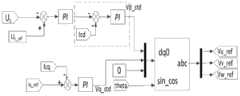
(3)通过电压外环和电流内环控制,并经过DQ反变换得到CSPWM的调制波,进行直流侧电容电压控制和无功补偿;(3) Through the control of the voltage outer loop and the current inner loop, and through DQ inverse transformation to obtain the modulation wave of CSPWM, the DC side capacitor voltage control and reactive power compensation are performed;
(4)将所述(1)、(2)中的相间能量修正值和子模块能量修正值与(3)中所得的调制波进行叠加,并与移相三角波进行比较,得到各子模块开关器件的出发脉冲,从而实现MMC-STATCOM的功能。(4) Superimpose the phase-to-phase energy correction value and submodule energy correction value in (1) and (2) with the modulation wave obtained in (3), and compare with the phase-shifted triangle wave to obtain the switching devices of each submodule The starting pulse, so as to realize the function of MMC-STATCOM.
较佳地,所述(1)中在各相调制波上附加相间能量修正值,以平衡能量在各相的分布具体为采用双闭环矢量控制,即外环采用电压PI控制,内环采用环流抑制控制器控制。Preferably, in the above (1), an energy correction value between phases is added to the modulation waves of each phase to balance the distribution of energy in each phase. Specifically, double closed-loop vector control is adopted, that is, the outer loop adopts voltage PI control, and the inner loop adopts circulating current Inhibition controller control.
较佳地,所述(2)中在各子模块调制波上附加子模块能量修正值,以平衡能量在各个子模块间的分布的具体方法为PI控制,即通过比较电容电压瞬时值和参考值,判断此刻电容的充、放电状态,从而修正电容充、放电的时间,进而平衡能量在所述各子模块间的分布。Preferably, in (2), the energy correction value of each sub-module is added to the modulation wave of each sub-module to balance the distribution of energy among the sub-modules. The specific method is PI control, that is, by comparing the instantaneous value of the capacitor voltage with the reference value, judge the charging and discharging state of the capacitor at the moment, thereby correcting the charging and discharging time of the capacitor, and then balance the distribution of energy among the sub-modules.
较佳地,所述(3)中通过电压外环和电流内环控制,并经过DQ反变换得到CSPWM的调制波,进行直流侧电容电压控制和无功补偿的具体方法为:计算MMC输出电流在DQ下的交、直轴分量,并与各自的目标值进行PI控制,PI控制输出为MMC输出电压在DQ坐标系下的值;通过DQ-ABC反变换,从而得到模块化多电平变流器的调制波的载波量。Preferably, in the above (3), the voltage outer loop and the current inner loop are controlled, and the modulation wave of CSPWM is obtained through DQ inverse transformation. The specific method for DC side capacitor voltage control and reactive power compensation is: calculate the MMC output current The orthogonal and direct axis components under DQ are PI controlled with their respective target values, and the PI control output is the value of the MMC output voltage in the DQ coordinate system; through DQ-ABC inverse transformation, a modular multi-level transformer can be obtained The carrier quantity of the modulated wave of the converter.
本发明由于采用上述的技术方案,具有以下优点:The present invention has the following advantages owing to adopting above-mentioned technical scheme:
1、建立了MMC-STATCOM解耦模型;1. Established the MMC-STATCOM decoupling model;
2、从能量观点解释了MMC-STATCOM的电容电压波动原因,并使用分块控制法控制了各模块电容电压;2. From the perspective of energy, the reasons for the fluctuation of the capacitor voltage of MMC-STATCOM are explained, and the capacitor voltage of each module is controlled by using the block control method;
3、直流侧电压波动控制和无功补偿功能共同使用DQ解耦结构控制,简化了控制结构;3. The DC side voltage fluctuation control and reactive power compensation functions are jointly controlled by DQ decoupling structure, which simplifies the control structure;
4、无功补偿性能良好,且动态响应速度较快。4. The reactive power compensation performance is good, and the dynamic response speed is fast.
附图说明Description of drawings
图1是本发明的基于模块化多电平变流器的无功补偿(MMC-STATCOM)方法流程图;Fig. 1 is a flow chart of the reactive power compensation (MMC-STATCOM) method based on the modular multilevel converter of the present invention;
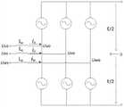
图2是本发明的基于模块化多电平变流器的无功补偿(MMC-STATCOM)方法中的MMC拓扑结构图;Fig. 2 is the MMC topology structure diagram in the reactive power compensation (MMC-STATCOM) method based on the modular multilevel converter of the present invention;
图3a本发明的基于模块化多电平变流器的无功补偿(MMC-STATCOM)方法所涉及的MMC-STATCOM原理图,Fig. 3a The schematic diagram of the MMC-STATCOM involved in the reactive power compensation (MMC-STATCOM) method based on the modular multilevel converter of the present invention,
图3b是图3a所示的MMC-STATCOM原理图的等效电路图;Figure 3b is an equivalent circuit diagram of the MMC-STATCOM schematic shown in Figure 3a;
图4为图2所示的基于模块化多电平变流器的无功补偿(MMC-STATCOM)方法中的步骤S2的流程图;Fig. 4 is a flow chart of step S2 in the reactive power compensation (MMC-STATCOM) method based on the modular multilevel converter shown in Fig. 2;
图5是本发明的基于模块化多电平变流器的无功补偿(MMC-STATCOM)方法中的子模块均压控制原理图;Fig. 5 is a schematic diagram of sub-module voltage equalization control in the reactive power compensation (MMC-STATCOM) method based on the modular multilevel converter of the present invention;
图6是本发明的基于模块化多电平变流器的无功补偿(MMC-STATCOM)方法中的相间稳压控制原理图;Fig. 6 is a schematic diagram of phase-to-phase voltage stabilization control in the reactive power compensation (MMC-STATCOM) method based on the modular multilevel converter of the present invention;
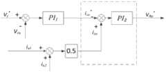
图7是本发明的基于模块化多电平变流器的无功补偿(MMC-STATCOM)方法的中直流侧稳压和无功补偿控制原理图;Fig. 7 is a control schematic diagram of DC side voltage stabilization and reactive power compensation of the reactive power compensation (MMC-STATCOM) method based on the modular multilevel converter of the present invention;
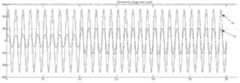
图8a是根据本发明的基于模块化多电平变流器的无功补偿(MMC-STATCOM)方法的进行的仿真结果中的U相子模块电容电压示意图;Fig. 8a is a schematic diagram of the U-phase sub-module capacitor voltage in the simulation results of the reactive power compensation (MMC-STATCOM) method based on the modular multilevel converter according to the present invention;
图8b是根据本发明的基于模块化多电平变流器的无功补偿(MMC-STATCOM)方法的进行的仿真结果中的MMC直流侧电压波形示意图;Fig. 8b is a schematic diagram of the MMC DC side voltage waveform in the simulation results of the reactive power compensation (MMC-STATCOM) method based on the modular multilevel converter according to the present invention;
图8c是根据本发明的基于模块化多电平变流器的无功补偿(MMC-STATCOM)方法的进行的仿真结果中的电网U相电压电流波形示意图。Fig. 8c is a schematic diagram of the U-phase voltage and current waveform of the power grid in the simulation results of the reactive power compensation based on the modular multilevel converter (MMC-STATCOM) method according to the present invention.
具体实施方specific implementation
下面结合说明书附图对本发明的基于模块化多电平变流器的无功补偿(MMC-STATCOM)方法作进一步详细的说明。The reactive power compensation (MMC-STATCOM) method based on the modular multilevel converter of the present invention will be further described in detail below in conjunction with the accompanying drawings.
本发明提供了一种基于模块化多电平变流器的无功补偿(MMC-STATCOM)方法,由于从能量角度而言,模块化多电平变流器的各相、各子模块和直流侧能量分布相互独立,因此,可进行分块控制,包括以下的部分:The present invention provides a reactive power compensation (MMC-STATCOM) method based on a modular multilevel converter. From an energy point of view, each phase, each sub-module and DC of a modular multilevel converter The side energy distribution is independent of each other, therefore, block control can be performed, including the following parts:
如图1所示:As shown in Figure 1:
步骤S1:根据MMC拓扑结构建立MMC-STATCOM解耦模型;Step S1: Establish an MMC-STATCOM decoupling model according to the MMC topology;
如图2、图3a和图3b所示,对于MMC-STATCOM建立解耦数学模型:考虑到MMC三相对称,且环流很小,则每相上下桥臂的两电感间电压为零,故可视为并联,故等效输出电感表达式为:As shown in Figure 2, Figure 3a and Figure 3b, a decoupling mathematical model is established for MMC-STATCOM: Considering that the three phases of MMC are symmetrical and the circulating current is small, the voltage between the two inductors of the upper and lower bridge arms of each phase is zero, so it can be It is regarded as parallel connection, so the equivalent output inductance expression is:
列写MMC三相电压、电流的时域表达式:List the time-domain expressions of MMC three-phase voltage and current:
将式(2)转换为DQ坐标系:Convert formula (2) to DQ coordinate system:
得出MMC输出无功功率在DQ坐标系下的表示为:It is obtained that the output reactive power of the MMC is expressed in the DQ coordinate system as:
Q=-1.5Udiq ⑷Q=-1.5Ud iq ⑷
其中,in,
L0为MMC每相桥臂串联的限流电感,Ls为MMC输出与电网相连的电感;L0 is the current-limiting inductance connected in series with each phase bridge arm of the MMC, and Ls is the inductance connected between the MMC output and the power grid;
iu、iv、iw分别为MMC三相输出的电流;iu ,iv , iw are the three-phase output currents of MMC respectively;
Vus、Vvs、Vws分别为电网侧MMC-STATCOM接入点电压;Vus , Vvs , Vws are the voltages of the MMC-STATCOM access point on the grid side;
Vuo、Vvo、Vwo分别为MMC-STATCOM输出电压;Vuo , Vvo , Vwo are MMC-STATCOM output voltage respectively;
id、iq分别为MMC-STATCOM输出的交、直轴电流;id and iq are the alternating current and direct axis current output by MMC-STATCOM respectively;
Ud、Uq分别为电网侧MMC-STATCOM接入点电压在DQ坐标系下的值;Ud and Uq are the voltage values of the grid-side MMC-STATCOM access point in the DQ coordinate system, respectively;
Uod、Uoq分别为MMC-STATCOM输出电压在DQ坐标系下的值。Uod and Uoq are the values of MMC-STATCOM output voltage in DQ coordinate system respectively.
参见图4所示,步骤S2:从能量观点分析步骤S1中建立的MMC-STATCOM解耦模型中电容电压波动的原因,得到各相、各子模块和直流侧能量分布相互独立,并进行分块控制:See Figure 4, Step S2: Analyze the cause of capacitor voltage fluctuations in the MMC-STATCOM decoupling model established in Step S1 from the energy point of view, and obtain that the energy distribution of each phase, each sub-module and DC side is independent of each other, and divide them into blocks control:
(1)在各相调制波上附加相间能量修正值,以平衡能量在各相的分布;各相间能量不平衡造成相间总电压不平衡,进而引起相间环流。因此通过抑制相间环流来平衡能量在各相的分布,具体方法为采用双闭环矢量控制:外环为电压PI控制,得到环流指令值,越小越好;内环为环流抑制控制器控制,输出为抑制环流量的电压修正值。(1) Add phase-to-phase energy correction values to the modulation waves of each phase to balance the distribution of energy in each phase; the imbalance of energy between phases causes the total voltage between phases to be unbalanced, which in turn causes inter-phase circulation. Therefore, the distribution of energy in each phase is balanced by suppressing the circulation between phases. The specific method is to adopt double closed-loop vector control: the outer loop is controlled by voltage PI, and the command value of the circulation is obtained, and the smaller the better; the inner loop is controlled by the circulation suppression controller, and the output It is the voltage correction value to suppress the circulation flow.
参加图5,例如:某相(比如U相)的电压修正值为正,说明其能量偏小,需要延长该相所有子模块的充电时间。Refer to Figure 5, for example: the voltage correction value of a certain phase (such as U phase) is positive, indicating that its energy is too small, and the charging time of all sub-modules of this phase needs to be extended.
(2)如图6所示,在各子模块调制波上附加子模块能量修正值,以平衡能量在各个子模块间的分布;各相能量平衡不能保证该相各个子模块能量平衡,因此需要平衡各相总能量在各子模块中的分布,同样,可采取在各子模块调制波上附加子模块能量修正值的方式,平衡能量在各个子模块间的分布的具体方法为PI控制,即通过比较电容电压瞬时值和参考值,判断此刻电容的充、放电状态,从而修正电容充、放电的时间,进而平衡能量在所述各子模块间的分布。(2) As shown in Figure 6, the energy correction value of each sub-module is added to the modulation wave of each sub-module to balance the distribution of energy among each sub-module; the energy balance of each phase cannot guarantee the energy balance of each sub-module of this phase, so it is necessary To balance the distribution of the total energy of each phase in each sub-module, similarly, the method of adding the sub-module energy correction value to the modulation wave of each sub-module can be adopted. The specific method to balance the distribution of energy among each sub-module is PI control, namely By comparing the instantaneous value of the capacitor voltage with the reference value, the charging and discharging state of the capacitor at the moment is judged, thereby correcting the charging and discharging time of the capacitor, and then balancing the energy distribution among the sub-modules.
(3)如图7所示,通过电压外环和电流内环控制,并经过DQ反变换得到CSPWM的调制波,进行直流侧电容电压控制和无功补偿;各相能量平衡,同时子模块能量平衡不能保证直流侧电容电压稳定,依然会引起各相与直流侧的环流。直流侧的能量损失是由MMC内部有功损耗引起的,可以通过MMC的输出电流在DQ坐标系下的有功电流分量进行控制。因此,选择MMC的直流侧电压控制和无功补偿功能同时控制,即通过计算MMC输出电流在DQ下的交、直轴分量,并与各自的目标值进行PI控制,PI控制输出为MMC输出电压在DQ坐标系下的值;而后,通过DQ-ABC反变换,得到MMC调制波的载波量。(3) As shown in Figure 7, through the control of the voltage outer loop and the current inner loop, and through DQ inverse transformation to obtain the CSPWM modulation wave, the DC side capacitor voltage control and reactive power compensation are performed; the energy of each phase is balanced, and the sub-module energy Balance cannot guarantee the stability of the capacitor voltage on the DC side, and it will still cause circulating currents between each phase and the DC side. The energy loss on the DC side is caused by the active power loss inside the MMC, which can be controlled by the active current component of the output current of the MMC in the DQ coordinate system. Therefore, the DC side voltage control and reactive power compensation functions of MMC are selected to be controlled at the same time, that is, by calculating the orthogonal and direct axis components of the MMC output current under DQ, and performing PI control with their respective target values, the PI control output is the MMC output voltage The value in the DQ coordinate system; then, through the DQ-ABC inverse transformation, the carrier quantity of the MMC modulated wave is obtained.
(4)将所述(1)、(2)中的相间能量修正值和子模块能量修正值与(3)中所得的调制波进行叠加,并与移相三角波进行比较,得到各子模块开关器件的出发脉冲,从而实现MMC-STATCOM的功能。例如:以U相为例,其上桥臂各子模块共用一个相同的调制波,叠加上各个子模块的电压修正值,按照载波移相原理,各子模块的三角载波各自相移一定角度后与上述得到的修正后的调制波比较得到“0”信号和“1”信号的开关信号,进而控制各子模块的IGBT开通和关断。(4) Superimpose the phase-to-phase energy correction value and submodule energy correction value in (1) and (2) with the modulation wave obtained in (3), and compare with the phase-shifted triangle wave to obtain the switching devices of each submodule The starting pulse, so as to realize the function of MMC-STATCOM. For example: take the U phase as an example, the sub-modules of the upper bridge arm share the same modulation wave, and the voltage correction value of each sub-module is superimposed. According to the principle of carrier phase shift, the triangular carrier wave of each sub-module is shifted by a certain angle. Compared with the modified modulation wave obtained above, switching signals of "0" signal and "1" signal are obtained, and then the IGBTs of each sub-module are controlled to be turned on and off.
使用matlab/Simulink按照图3(a)建立模型验证本发明的有效性,仿真结果请参见图8a-8c所示。Use matlab/Simulink to build a model according to Figure 3(a) to verify the effectiveness of the present invention, and the simulation results are shown in Figures 8a-8c.
本发明由于采用上述的技术方案,具有以下优点:The present invention has the following advantages owing to adopting above-mentioned technical scheme:
1、建立了MMC-STATCOM解耦模型;1. Established the MMC-STATCOM decoupling model;
2、从能量观点解释了MMC-STATCOM的电容电压波动原因,并使用分块控制法控制了各模块电容电压;2. From the perspective of energy, the reasons for the fluctuation of the capacitor voltage of MMC-STATCOM are explained, and the capacitor voltage of each module is controlled by using the block control method;
3、直流侧电压波动控制和无功补偿功能共同使用DQ解耦结构控制,简化了控制结构;3. The DC side voltage fluctuation control and reactive power compensation functions are jointly controlled by DQ decoupling structure, which simplifies the control structure;
4、无功补偿性能良好,且动态响应速度较快。4. The reactive power compensation performance is good, and the dynamic response speed is fast.
上述公开的仅为本发明的具体实施例,该实施例只为更清楚的说明本发明所用,而并非对本发明的限定,任何本领域的技术人员能思之的变化,都应落在保护范围内。The above-mentioned disclosure is only a specific embodiment of the present invention, which is only used to illustrate the present invention more clearly, but not to limit the present invention. Any changes that those skilled in the art can think of should fall within the scope of protection Inside.
Claims (6)
Priority Applications (1)
| Application Number | Priority Date | Filing Date | Title |
|---|---|---|---|
| CN201310352413.1ACN103441512B (en) | 2013-08-13 | 2013-08-13 | Modular Multilevel Converter Based Reactive Power Compensation (MMC-STATCOM) Method |
Applications Claiming Priority (1)
| Application Number | Priority Date | Filing Date | Title |
|---|---|---|---|
| CN201310352413.1ACN103441512B (en) | 2013-08-13 | 2013-08-13 | Modular Multilevel Converter Based Reactive Power Compensation (MMC-STATCOM) Method |
Publications (2)
| Publication Number | Publication Date |
|---|---|
| CN103441512Atrue CN103441512A (en) | 2013-12-11 |
| CN103441512B CN103441512B (en) | 2016-08-17 |
Family
ID=49695194
Family Applications (1)
| Application Number | Title | Priority Date | Filing Date |
|---|---|---|---|
| CN201310352413.1AExpired - Fee RelatedCN103441512B (en) | 2013-08-13 | 2013-08-13 | Modular Multilevel Converter Based Reactive Power Compensation (MMC-STATCOM) Method |
Country Status (1)
| Country | Link |
|---|---|
| CN (1) | CN103441512B (en) |
Cited By (12)
| Publication number | Priority date | Publication date | Assignee | Title |
|---|---|---|---|---|
| CN103872693A (en)* | 2014-04-10 | 2014-06-18 | 南京航空航天大学 | Non-constant direct-current bus voltage type MMC-STATCOM |
| CN104993533A (en)* | 2015-06-30 | 2015-10-21 | 上海交通大学 | Modular multilevel converter inter-bridge-arm energy balance control method |
| WO2015184955A1 (en)* | 2014-06-03 | 2015-12-10 | 南方电网科学研究院有限责任公司 | Voltage source type dc ice melting and static synchronous compensation device and method for controlling same |
| US9318974B2 (en) | 2014-03-26 | 2016-04-19 | Solaredge Technologies Ltd. | Multi-level inverter with flying capacitor topology |
| CN106026163A (en)* | 2016-05-27 | 2016-10-12 | 南京工程学院 | MMC-based low-voltage ride through control method and system of photovoltaic grid-connected inverter |
| CN106816883A (en)* | 2017-03-06 | 2017-06-09 | 天津平高智能电气有限公司 | Three-phase imbalance regulating system parallel connection input coefficient, control method and device |
| CN106887856A (en)* | 2017-03-06 | 2017-06-23 | 天津平高智能电气有限公司 | Three-phase imbalance adjustment control method, device and three-phase imbalance regulating system |
| CN107332257A (en)* | 2017-08-24 | 2017-11-07 | 上海交通大学 | A kind of STATCOM and its control method |
| US9941813B2 (en) | 2013-03-14 | 2018-04-10 | Solaredge Technologies Ltd. | High frequency multi-level inverter |
| CN110571825A (en)* | 2019-09-06 | 2019-12-13 | 中国电力科学研究院有限公司 | A static synchronous compensator model parameter identification method and system |
| CN110994660A (en)* | 2019-11-07 | 2020-04-10 | 长沙理工大学 | Optimization method of MMC power operation interval based on energy flow law |
| CN114123222A (en)* | 2021-09-26 | 2022-03-01 | 国网四川省电力公司经济技术研究院 | Method and system for voltage stabilization of traction network under regenerative braking condition of EMU |
Citations (3)
| Publication number | Priority date | Publication date | Assignee | Title |
|---|---|---|---|---|
| CN102739071A (en)* | 2012-06-20 | 2012-10-17 | 西安交通大学 | Method for controlling direct current capacitor voltage of modular multi-level converter based on circulating current decoupling |
| CN103036410A (en)* | 2012-12-01 | 2013-04-10 | 中国科学院电工研究所 | Bridge arm current decoupling control method for modularization multi-level converter |
| CN103095167A (en)* | 2012-12-13 | 2013-05-08 | 国网智能电网研究院 | Three-phase modulation multi-level converter energy balance control method |
- 2013
- 2013-08-13CNCN201310352413.1Apatent/CN103441512B/ennot_activeExpired - Fee Related
Patent Citations (3)
| Publication number | Priority date | Publication date | Assignee | Title |
|---|---|---|---|---|
| CN102739071A (en)* | 2012-06-20 | 2012-10-17 | 西安交通大学 | Method for controlling direct current capacitor voltage of modular multi-level converter based on circulating current decoupling |
| CN103036410A (en)* | 2012-12-01 | 2013-04-10 | 中国科学院电工研究所 | Bridge arm current decoupling control method for modularization multi-level converter |
| CN103095167A (en)* | 2012-12-13 | 2013-05-08 | 国网智能电网研究院 | Three-phase modulation multi-level converter energy balance control method |
Non-Patent Citations (1)
| Title |
|---|
| 王奎 等: "模块化多电平变换器电压平衡控制", 《清华大学学报(自然科学版)》, vol. 51, no. 7, 31 July 2011 (2011-07-31), pages 909 - 913* |
Cited By (30)
| Publication number | Priority date | Publication date | Assignee | Title |
|---|---|---|---|---|
| US9941813B2 (en) | 2013-03-14 | 2018-04-10 | Solaredge Technologies Ltd. | High frequency multi-level inverter |
| US11742777B2 (en) | 2013-03-14 | 2023-08-29 | Solaredge Technologies Ltd. | High frequency multi-level inverter |
| US11545912B2 (en) | 2013-03-14 | 2023-01-03 | Solaredge Technologies Ltd. | High frequency multi-level inverter |
| US12119758B2 (en) | 2013-03-14 | 2024-10-15 | Solaredge Technologies Ltd. | High frequency multi-level inverter |
| US10700588B2 (en) | 2014-03-26 | 2020-06-30 | Solaredge Technologies Ltd. | Multi-level inverter |
| US10680506B2 (en) | 2014-03-26 | 2020-06-09 | Solaredge Technologies Ltd. | Multi-level inverter |
| US11855552B2 (en) | 2014-03-26 | 2023-12-26 | Solaredge Technologies Ltd. | Multi-level inverter |
| US11632058B2 (en) | 2014-03-26 | 2023-04-18 | Solaredge Technologies Ltd. | Multi-level inverter |
| US11296590B2 (en) | 2014-03-26 | 2022-04-05 | Solaredge Technologies Ltd. | Multi-level inverter |
| US12136890B2 (en) | 2014-03-26 | 2024-11-05 | Solaredge Technologies Ltd. | Multi-level inverter |
| US10153685B2 (en) | 2014-03-26 | 2018-12-11 | Solaredge Technologies Ltd. | Power ripple compensation |
| US10886832B2 (en) | 2014-03-26 | 2021-01-05 | Solaredge Technologies Ltd. | Multi-level inverter |
| US10404154B2 (en) | 2014-03-26 | 2019-09-03 | Solaredge Technologies Ltd | Multi-level inverter with flying capacitor topology |
| US10886831B2 (en) | 2014-03-26 | 2021-01-05 | Solaredge Technologies Ltd. | Multi-level inverter |
| US9318974B2 (en) | 2014-03-26 | 2016-04-19 | Solaredge Technologies Ltd. | Multi-level inverter with flying capacitor topology |
| US10680505B2 (en) | 2014-03-26 | 2020-06-09 | Solaredge Technologies Ltd. | Multi-level inverter |
| CN103872693A (en)* | 2014-04-10 | 2014-06-18 | 南京航空航天大学 | Non-constant direct-current bus voltage type MMC-STATCOM |
| WO2015184955A1 (en)* | 2014-06-03 | 2015-12-10 | 南方电网科学研究院有限责任公司 | Voltage source type dc ice melting and static synchronous compensation device and method for controlling same |
| CN104993533B (en)* | 2015-06-30 | 2017-06-09 | 上海交通大学 | Energy equilibrium control method between modular multi-level converter bridge arm |
| CN104993533A (en)* | 2015-06-30 | 2015-10-21 | 上海交通大学 | Modular multilevel converter inter-bridge-arm energy balance control method |
| CN106026163B (en)* | 2016-05-27 | 2019-04-09 | 南京工程学院 | A low-voltage ride-through control method and system based on MMC photovoltaic grid-connected inverter |
| CN106026163A (en)* | 2016-05-27 | 2016-10-12 | 南京工程学院 | MMC-based low-voltage ride through control method and system of photovoltaic grid-connected inverter |
| CN106887856B (en)* | 2017-03-06 | 2020-06-09 | 天津平高智能电气有限公司 | Three-phase unbalance adjustment control method, device and three-phase unbalance adjustment system |
| CN106887856A (en)* | 2017-03-06 | 2017-06-23 | 天津平高智能电气有限公司 | Three-phase imbalance adjustment control method, device and three-phase imbalance regulating system |
| CN106816883A (en)* | 2017-03-06 | 2017-06-09 | 天津平高智能电气有限公司 | Three-phase imbalance regulating system parallel connection input coefficient, control method and device |
| CN107332257A (en)* | 2017-08-24 | 2017-11-07 | 上海交通大学 | A kind of STATCOM and its control method |
| CN110571825A (en)* | 2019-09-06 | 2019-12-13 | 中国电力科学研究院有限公司 | A static synchronous compensator model parameter identification method and system |
| CN110994660A (en)* | 2019-11-07 | 2020-04-10 | 长沙理工大学 | Optimization method of MMC power operation interval based on energy flow law |
| CN114123222A (en)* | 2021-09-26 | 2022-03-01 | 国网四川省电力公司经济技术研究院 | Method and system for voltage stabilization of traction network under regenerative braking condition of EMU |
| CN114123222B (en)* | 2021-09-26 | 2024-11-29 | 国网四川省电力公司经济技术研究院 | Traction network voltage stabilizing method and system for motor train unit under regenerative braking working condition |
Also Published As
| Publication number | Publication date |
|---|---|
| CN103441512B (en) | 2016-08-17 |
Similar Documents
| Publication | Publication Date | Title |
|---|---|---|
| CN103441512B (en) | Modular Multilevel Converter Based Reactive Power Compensation (MMC-STATCOM) Method | |
| CN103701350B (en) | Low frequency operating mode counterdie blocking Multilevel Inverters voltage fluctuation of capacitor suppressing method | |
| CN104038091B (en) | Three-level converter direct-current side neutral-point voltage balance control method based on SVPWM | |
| CN102638049B (en) | A Phase-to-Phase Voltage Equalization Control Method of Chained Delta Connection STATCOM DC Bus | |
| CN103219908B (en) | Method for controlling balance of direct current side of cascaded grid-connected inverter based on zero sequence and negative sequence voltage injection | |
| CN103095167A (en) | Three-phase modulation multi-level converter energy balance control method | |
| CN104953606A (en) | Networked layered compensation method for voltage unbalance of PCC (Point of Common Coupling) of islanded microgrid | |
| CN104218590A (en) | Unbalance voltage compensation and control method based on virtual synchronous machine | |
| CN106998071A (en) | A kind of MMC STATCOM unbalanced load compensating control methods based on bridge arm current | |
| CN107394818B (en) | A grid-connected operation control method and device for an energy storage battery based on an energy storage converter | |
| CN104682390A (en) | Alternating current (AC) hybrid active power filter system for high-voltage direct current (DC) transmission, and control method thereof | |
| CN105098804A (en) | Method and device for controlling three-phase unbalanced current of virtual synchronous generator | |
| CN112701710B (en) | Energy storage converter stability control method based on alternating current constant power load dynamic performance | |
| CN105337297A (en) | Balancing method and the device for state of charge (SOC) of energy storage system | |
| CN103825478A (en) | Control method of modular multilevel converter based on power frequency fixed switching frequency | |
| CN105071403A (en) | Reactive compensation device based on double H-bridge modular multilevel topology and control method | |
| CN104201679A (en) | Current mode inverting control strategy for inhibiting current harmonic waves and three phase imbalance in micro grid | |
| CN102957153A (en) | DC neutral point balance control method of three-phase four-wire three-leg static synchronous compensator | |
| CN107196540A (en) | A kind of modularization multi-level converter direct current harmonic suppressing method | |
| CN107222118A (en) | A kind of UPFC controllers and its control method based on observer and MMC | |
| Wang et al. | Circulating current suppression for MMC-HVDC under unbalanced grid conditions | |
| CN107947623B (en) | A multi-mode autonomous operation control method for bidirectional AC/DC converter under unbalanced load conditions | |
| Elserougi et al. | A transformerless STATCOM based on a hybrid Boost Modular Multilevel Converter with reduced number of switches | |
| CN112952867B (en) | Method for inhibiting unbalance of output voltage of energy storage power converter under asymmetric load | |
| CN106385192A (en) | Three-level four-leg inverter control method |
Legal Events
| Date | Code | Title | Description |
|---|---|---|---|
| C06 | Publication | ||
| PB01 | Publication | ||
| C10 | Entry into substantive examination | ||
| SE01 | Entry into force of request for substantive examination | ||
| C14 | Grant of patent or utility model | ||
| GR01 | Patent grant | ||
| CF01 | Termination of patent right due to non-payment of annual fee | Granted publication date:20160817 Termination date:20190813 | |
| CF01 | Termination of patent right due to non-payment of annual fee |