CN103438980A - Method and device for liquid surface wave detection based on linear array CCD and linear infrared laser - Google Patents
Method and device for liquid surface wave detection based on linear array CCD and linear infrared laserDownload PDFInfo
- Publication number
- CN103438980A CN103438980ACN2013103909539ACN201310390953ACN103438980ACN 103438980 ACN103438980 ACN 103438980ACN 2013103909539 ACN2013103909539 ACN 2013103909539ACN 201310390953 ACN201310390953 ACN 201310390953ACN 103438980 ACN103438980 ACN 103438980A
- Authority
- CN
- China
- Prior art keywords
- array ccd
- linear array
- linear
- liquid surface
- infrared laser
- Prior art date
- Legal status (The legal status is an assumption and is not a legal conclusion. Google has not performed a legal analysis and makes no representation as to the accuracy of the status listed.)
- Granted
Links
Images


Landscapes
- Investigating Or Analysing Materials By Optical Means (AREA)
- Length Measuring Devices By Optical Means (AREA)
Abstract
Translated fromChinese
Description
Translated fromChinese技术领域technical field
本发明涉及一种基于线阵CCD和线状红外激光的液体表面波探测方法及装置,属于液体表面波检测领域。The invention relates to a liquid surface wave detection method and device based on a linear array CCD and a linear infrared laser, belonging to the field of liquid surface wave detection.
背景技术Background technique
在物理学中,表面波是一种沿着两种不同流体界面传播的机械波。液体表面波通常是指沿液体和空气界面传播的一种机械波,通常是由于液体受到扰动后形成的。如果我们研究的液体表面波波长或者振幅比较小,我们就无法用肉眼看到它,这给液体表面波频率的测量带来一定的困难。In physics, a surface wave is a mechanical wave that propagates along the interface of two different fluids. Liquid surface wave usually refers to a kind of mechanical wave propagating along the interface between liquid and air, which is usually formed after the liquid is disturbed. If the wavelength or amplitude of the liquid surface wave we study is relatively small, we cannot see it with the naked eye, which brings certain difficulties to the measurement of the liquid surface wave frequency.
目前测量液体表面波的方法主要包括接触式测量和非接触式测量两种方法。由于接触式测量方法会对待测水表面波引入人为干扰,所以液体表面波的测量应优先考虑非接触式的测量。在非接触式测量方法中,又分为直接测量法,和利用光的衍射、干涉性质的间接测量法。The current methods of measuring liquid surface waves mainly include contact measurement and non-contact measurement. Since the contact measurement method will introduce artificial interference to the water surface wave to be measured, the measurement of the liquid surface wave should give priority to the non-contact measurement. In the non-contact measurement method, it is divided into direct measurement method and indirect measurement method using the diffraction and interference properties of light.
在直接测量法中,比较典型的是童培雄等人在论文“测量水的振动频率与水波传播速度”中提出的基于硅光电池和点状激光的测量方法,该方法利用硅光电池的电压与照射面积之间的关系估算出光斑的位置。但由于硅光电池存在死区电压,以及光电参数不均匀等原因使得测量精度比较差。In the direct measurement method, the typical one is the measurement method based on silicon photocell and point laser proposed by Tong Peixiong et al. in the paper "Measurement of Water Vibration Frequency and Water Wave Propagation Velocity". The relationship between the estimation of the position of the spot. However, the measurement accuracy is relatively poor due to the dead zone voltage of the silicon photovoltaic cell and the uneven photoelectric parameters.
在间接测量法中,对于不同频段的液体有不同的方法。苗润才等人用衍射的方法测量几百赫兹的液体表面波的物理特性,实验观察到了表面波的衍射效应,而且得到了几乎100%的衍射效率,还讨论了衍射条纹间距与液体表面张力的关系,并对液体表面波的衰减特性进行了研究;对于频率为几赫兹或更小的液体表面波,Bartor等人曾采用表面波斜率激光扫描技术分析过这些频率以下的液体表面波,但在他的研究中,液体必须染色,不适合于像水这样的透明液体;对于频率为几十赫兹的液体表面波,张晓琳等人曾提供一种基于散射激光多普勒效应的液体表面波探测方法及装置,解决了之前对液体表面波频率和振幅进行测量的激光干涉技术中,要求接收主反射光,并且要求光路输出和接收部分的角度严格匹配的问题,但是它的测量频率的量程有限,只能探测0-40赫兹的表面波,同时设备也较复杂,成本高。In the indirect measurement method, there are different methods for liquids with different frequency bands. Miao Runcai and others used the diffraction method to measure the physical properties of liquid surface waves of several hundred Hz. They observed the diffraction effect of surface waves and obtained almost 100% diffraction efficiency. They also discussed the relationship between the diffraction fringe spacing and the liquid surface tension. relationship, and studied the attenuation characteristics of liquid surface waves; for liquid surface waves with a frequency of several hertz or less, Bartor et al. have used surface wave slope laser scanning technology to analyze liquid surface waves below these frequencies, but In his research, the liquid must be dyed, which is not suitable for transparent liquids like water; for liquid surface waves with a frequency of tens of hertz, Zhang Xiaolin et al. have provided a liquid surface wave detection based on scattered laser Doppler effect The method and device solve the problem that in the previous laser interferometry technology for measuring the frequency and amplitude of liquid surface waves, the main reflected light is required to be received, and the angle between the output of the optical path and the receiving part is required to be strictly matched, but its measurement frequency range is limited , can only detect surface waves of 0-40 Hz, and the equipment is more complicated and the cost is high.
本发明涉及一种基于线阵CCD和线状红外激光的液体表面波探测方法,属于上述的非接触测量方法中的直接测量法。The invention relates to a liquid surface wave detection method based on a linear array CCD and a linear infrared laser, which belongs to the direct measurement method in the above-mentioned non-contact measurement method.
发明内容Contents of the invention
本发明的目的是提供一种基于线阵CCD和线状红外激光的液体表面波探测方法及装置。它解决了现有基于激光干涉的液体表面波探测方法需要严格匹配光路输出和接收部分的角度的问题,同时也解决了基于散射激光多普勒效应的液体表面波探测方法量程不够广的问题。The object of the present invention is to provide a liquid surface wave detection method and device based on a linear array CCD and a linear infrared laser. It solves the problem that the existing liquid surface wave detection method based on laser interference needs to strictly match the angle of the output and receiving parts of the optical path, and also solves the problem that the range of the liquid surface wave detection method based on scattered laser Doppler effect is not wide enough.
其测量方法包括下述步骤:Its measurement method includes the following steps:
步骤一:用线状红外激光器发射的激光线照射到待测液体表面,使得激光面和液面的交线垂直于激光器的发射方向,光线经液体表面后通过可见光滤波器滤掉可见光成分;Step 1: Use the laser line emitted by the linear infrared laser to irradiate the surface of the liquid to be tested, so that the intersection line between the laser surface and the liquid surface is perpendicular to the emission direction of the laser, and the visible light components are filtered out by the visible light filter after the light passes through the liquid surface;
步骤二:步骤一得到的纯红外激光线垂直照射到线阵CCD上,线阵CCD输出数字视频信号;Step 2: The pure infrared laser line obtained in
步骤三:步骤二得到的数字视频信号经过滤波和模式匹配得到光斑中心点坐标,所述光斑是一条中间亮周围暗的粗线;线阵CCD输出的数字视频信号的时序图如图6所示,该信号为半数字半模拟信号,线阵CCD信号处理芯片是将上述半数字半模拟的数字视频信号转换为数字信号并将信号送给图像处理芯片;Step 3: The digital video signal obtained in
图像处理芯片的处理过程包括采样、滤波、匹配三个步骤:The processing process of the image processing chip includes three steps of sampling, filtering and matching:
3.1.采样3.1. Sampling
上述数字信号被图像处理器采样,得到原始帧序列A[n],序列的长度设为N;The above digital signal is sampled by the image processor to obtain the original frame sequence A[n], and the length of the sequence is set to N;
3.2.滤波3.2. Filtering
对上述原始帧序列A[n]进行软件滤波(滤波的作用是滤除环境光线干扰以及电噪声干扰)得到滤波后的帧序列,记为F[n],其中n代表线阵CCD的第n个像素(在本文的描述中坐标指的就是像素序号);Perform software filtering on the above original frame sequence A[n] (the function of filtering is to filter out ambient light interference and electrical noise interference) to obtain the filtered frame sequence, denoted as F[n], where n represents the nth of the linear array CCD pixels (in the description of this article, the coordinates refer to the pixel serial number);
3.3.匹配3.3. Matching
光斑在线阵CCD感光区域的光强分布类似正态分布,且当光斑中心靠近线阵CCD感光区域的边缘时会有部分光线照射在线阵CCD感光区域外,针对上述情况,本专利采用基于预存模板的匹配算法精确的得到了光斑中心的坐标。匹配算法的具体流程如下:图像处理器预存了光斑中心在每个坐标位置的模板,例如:The light intensity distribution of the light spot on the linear CCD photosensitive area is similar to the normal distribution, and when the center of the light spot is close to the edge of the linear CCD photosensitive area, some light will irradiate outside the linear CCD photosensitive area. The matching algorithm accurately obtains the coordinates of the spot center. The specific process of the matching algorithm is as follows: the image processor pre-stores the template with the spot center at each coordinate position, for example:
第0像素点预存的模板序列为M[0],The template sequence pre-stored at the 0th pixel is M[0],
……
第i像素点预存的模板序列为M[i],The template sequence pre-stored at the i-th pixel is M[i],
……
第N像素点预存的模板序列为M[N],The template sequence pre-stored at the Nth pixel is M[N],
M[n][i]的计算公式如下:The calculation formula of M[n][i] is as follows:
n表示光斑中心在第n个坐标位置n indicates that the center of the spot is at the nth coordinate position
i表示模板序列的第i个值i represents the i-th value of the template sequence
其中n=0,1,2…N i=0,1,2…Nwhere n=0,1,2...N i=0,1,2...N
δ为常数,δ越大对应光斑越宽,反之则越窄,δ可根据实际光斑宽度进行调整。δ is a constant, the larger δ corresponds to the wider the spot, and vice versa, the narrower the spot, δ can be adjusted according to the actual spot width.
将滤波后的帧序F[n]与每个模板序列做向量积运算,将计算结果记为R,计算的公式如下:Do the vector product operation between the filtered frame sequence F[n] and each template sequence, and record the calculation result as R. The calculation formula is as follows:
取使R[n]值最大的那个n为光斑中心的坐标。Take the n that maximizes the value of R[n] as the coordinates of the center of the spot.
步骤四:步骤三得到的光斑中心坐标发送到上位机进行显示表面波的时域信息;同时对时域波形进行快速傅里叶变换,显示表面波的频域信息。Step 4: The spot center coordinates obtained in
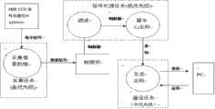
基于线阵CCD和线状红外激光的液体表面波探测装置由激光发射模块,光线位置检测模块,图像处理三部分组成(图1,装置结构示意图)。The liquid surface wave detection device based on linear array CCD and linear infrared laser consists of three parts: laser emission module, light position detection module and image processing (Figure 1, schematic diagram of device structure).
为了测量来自各个方向的水表面波,本发明选用线状激光器射出线状光线,这样可以保证无论表面波来自什么方向,反射光线始终能够照射到线阵In order to measure water surface waves from various directions, the present invention uses a linear laser to emit linear light, which can ensure that no matter what direction the surface wave comes from, the reflected light can always irradiate the linear array
CCD上。从而解决了基于激光干涉的液体表面波探测方法解决不了的光路匹配问题。on the CCD. Therefore, the optical path matching problem that cannot be solved by the liquid surface wave detection method based on laser interference is solved.
由于环境中存在可见光的干扰,本发明选择红外激光头发射红外激光线;并在线阵CCD之前加装一片可见光滤光片滤除掉环境中的可见光,从而提高测量仪器抗环境干扰的能力。Due to the interference of visible light in the environment, the present invention selects the infrared laser head to emit infrared laser lines; and installs a visible light filter before the line array CCD to filter out the visible light in the environment, thereby improving the ability of the measuring instrument to resist environmental interference.
本发明采用帧率很高的线阵CCD代替帧率低的面阵CCD作为感光传感器,直接测量被光杠杆放大的位移信号,从而达到较高的精度和量程,实验表明该装置可以较准确的测量0-200赫兹的表面波。The present invention uses a linear array CCD with a high frame rate instead of an area array CCD with a low frame rate as a photosensitive sensor to directly measure the displacement signal amplified by the optical lever, thereby achieving higher precision and range. Experiments show that the device can be more accurate. Measures surface waves from 0-200 Hz.
此外本发明还对线阵CCD输出的数字视频信号进行采样、滤波、模式匹配,最终得到光斑中心的坐标,发给上位机软件。上位机软件负责显示时域波形,以及对时域波形进行FFT变换后的频域波形。In addition, the present invention also performs sampling, filtering, and pattern matching on the digital video signal output by the linear array CCD, finally obtains the coordinates of the center of the light spot, and sends it to the upper computer software. The host computer software is responsible for displaying the time-domain waveform and the frequency-domain waveform after FFT transforming the time-domain waveform.
本发明的优点是:The advantages of the present invention are:
本发明利用线状激光代替点状激光使得无论哪个方向来的表面波引起的光路偏移都会被线阵CCD所测量到,因此可以测量来自各个方向的表面波,而不用像基于激光干涉的液体表面波探测方法那样每次都要调整光路。同时本发明使用线阵CCD而不用面阵CCD作为感光元件使得帧率得到大幅提高,实验表明该装置可以较准确的测量0-200赫兹的表面波。最后,本发明还具有结构简单、成本低、操作简单、维护容易等优点。The present invention uses a linear laser instead of a point laser so that the optical path deviation caused by the surface wave from any direction will be measured by the linear array CCD, so the surface wave from all directions can be measured instead of liquid based on laser interference As in the surface wave detection method, the optical path needs to be adjusted each time. At the same time, the present invention uses a linear array CCD instead of an area array CCD as a photosensitive element, so that the frame rate is greatly improved. Experiments show that the device can more accurately measure surface waves of 0-200 Hz. Finally, the present invention also has the advantages of simple structure, low cost, simple operation and easy maintenance.
附图说明Description of drawings
图1为装置结构示意图;Fig. 1 is a schematic diagram of the device structure;
图2为线状激光光路图;Figure 2 is a linear laser light path diagram;
图3为硬件结构图;Fig. 3 is a hardware structural diagram;
图4为软件的DARTS任务分解图;Figure 4 is a decomposition diagram of the DARTS task of the software;
图5为数字视频信号时序图;Fig. 5 is a digital video signal timing diagram;
图6为样机的测量结果。Figure 6 shows the measurement results of the prototype.
具体实施方式Detailed ways
本发明涉及的一种基于线阵CCD和线状红外激光的液体表面波探测装置的一种实施方式如下所示:An embodiment of a liquid surface wave detection device based on a linear array CCD and a linear infrared laser related to the present invention is as follows:
装置的硬件可由线阵CCD:TCD1209;线阵CCD信号处理芯片:AD9943;CPLD:EPM240T100C5N;微控制器:STM32F103RBT6以及PC组成(图3硬件结构图)。The hardware of the device can be composed of linear array CCD: TCD1209; linear array CCD signal processing chip: AD9943; CPLD: EPM240T100C5N; microcontroller: STM32F103RBT6 and PC (Figure 3 hardware structure diagram).
微控制器中的软件负责采集CCD信号处理芯片输出的电平信号,并将该电平信号转换成像素信号保存在帧缓存中,然后从帧缓存中获取帧数据,并对其进行软件滤波处理,最后通过如上介绍的匹配算法得到光斑中心坐标并通过串口发给PC。PC端的上位机软件则负责显示表面波的时域波形,以及对时域波形进行FFT变换,从而显示表面波的频域波形。可选择开源免费的FreeRTOS作为下位机的实时操作系统,基于DARTS方法的任务分解图如图4所示。The software in the microcontroller is responsible for collecting the level signal output by the CCD signal processing chip, converting the level signal into a pixel signal and saving it in the frame buffer, and then obtaining the frame data from the frame buffer, and performing software filtering on it , and finally get the coordinates of the center of the spot through the matching algorithm introduced above and send it to the PC through the serial port. The host computer software on the PC side is responsible for displaying the time-domain waveform of the surface wave, and performing FFT transformation on the time-domain waveform to display the frequency-domain waveform of the surface wave. The open source and free FreeRTOS can be selected as the real-time operating system of the lower computer. The task decomposition diagram based on the DARTS method is shown in Figure 4.
激光发射模块和光线位置检测模块可以用铁架台按照如下的要求固定(图1,装置结构示意图)。固定后需保证:The laser emission module and the light position detection module can be fixed with an iron stand according to the following requirements (Figure 1, a schematic diagram of the device structure). After fixing, it is necessary to ensure that:
1、激光面以一定角度(如与水面成30°夹角)入射水面;1. The laser surface is incident on the water surface at a certain angle (such as an angle of 30° with the water surface);
2、轴向旋转激光头使得激光面和水面的交线最短(图2,线状激光光路图);2. The axial rotation of the laser head makes the intersection line between the laser surface and the water surface the shortest (Fig. 2, linear laser light path diagram);
3、保持水面平静,调整线阵CCD的位置使得线阵CCD所在的平面与反射激光面垂直相交于线阵CCD感光区域的中点;3. Keep the water surface calm, adjust the position of the linear array CCD so that the plane where the linear array CCD is located and the reflective laser surface perpendicularly intersect at the midpoint of the linear array CCD photosensitive area;
固定好激光发射模块和光线位置检测模块后,再将光线位置检测模块的输出线连接到图像处理模块。给激光发射模块和光线位置检测模块通电后,打开上位机软件,水表面波测量仪开始工作。此时当水面有表面波传播至交线附时,PC上将显示该表面波放大后的波形以及频谱分布。After fixing the laser emitting module and the light position detection module, connect the output line of the light position detection module to the image processing module. After powering on the laser emission module and the light position detection module, open the host computer software, and the water surface wave measuring instrument starts to work. At this time, when there is a surface wave propagating to the intersection line on the water surface, the amplified waveform and spectrum distribution of the surface wave will be displayed on the PC.
Claims (7)
Translated fromChinesePriority Applications (1)
| Application Number | Priority Date | Filing Date | Title |
|---|---|---|---|
| CN201310390953.9ACN103438980B (en) | 2013-09-01 | 2013-09-01 | Method and device for liquid surface wave detection based on linear array CCD and linear infrared laser |
Applications Claiming Priority (1)
| Application Number | Priority Date | Filing Date | Title |
|---|---|---|---|
| CN201310390953.9ACN103438980B (en) | 2013-09-01 | 2013-09-01 | Method and device for liquid surface wave detection based on linear array CCD and linear infrared laser |
Publications (2)
| Publication Number | Publication Date |
|---|---|
| CN103438980Atrue CN103438980A (en) | 2013-12-11 |
| CN103438980B CN103438980B (en) | 2015-07-15 |
Family
ID=49692676
Family Applications (1)
| Application Number | Title | Priority Date | Filing Date |
|---|---|---|---|
| CN201310390953.9AExpired - Fee RelatedCN103438980B (en) | 2013-09-01 | 2013-09-01 | Method and device for liquid surface wave detection based on linear array CCD and linear infrared laser |
Country Status (1)
| Country | Link |
|---|---|
| CN (1) | CN103438980B (en) |
Cited By (6)
| Publication number | Priority date | Publication date | Assignee | Title |
|---|---|---|---|---|
| CN104457959A (en)* | 2014-12-05 | 2015-03-25 | 燕山大学 | Vibration testing system |
| CN110375954A (en)* | 2019-07-09 | 2019-10-25 | 浙江海洋大学 | A kind of vortex-induced vibration wake flow is released experimental rig and method |
| CN110375953A (en)* | 2019-07-09 | 2019-10-25 | 浙江海洋大学 | Vortex-induced vibration wake flow based on light refraction is released experimental rig and test method |
| WO2021017828A1 (en)* | 2019-07-27 | 2021-02-04 | 复旦大学 | High-precision method for measuring high-frequency standing wave amplitude distribution |
| CN112595385A (en)* | 2020-11-25 | 2021-04-02 | 创新奇智(南京)科技有限公司 | Target height obtaining method and device |
| CN116202615A (en)* | 2023-03-06 | 2023-06-02 | 哈尔滨工业大学(深圳) | A liquid surface wave characterization system |
Citations (4)
| Publication number | Priority date | Publication date | Assignee | Title |
|---|---|---|---|---|
| CN101710154A (en)* | 2009-12-23 | 2010-05-19 | 哈尔滨工业大学 | Liquid surface wave detecting method and device based on scattering laser Doppler effect |
| CN101762817A (en)* | 2010-01-29 | 2010-06-30 | 哈尔滨工业大学 | Laser imaging based high-resolution method for detecting micro-scale wave of sea wave |
| CN101930074A (en)* | 2010-01-29 | 2010-12-29 | 哈尔滨工业大学 | A Microscale Wave Detection Device Based on Laser Imaging |
| CN102607788A (en)* | 2012-03-27 | 2012-07-25 | 西安航空技术高等专科学校 | Device and method for detecting vibration isolation performance consistency of oversized optical platform |
- 2013
- 2013-09-01CNCN201310390953.9Apatent/CN103438980B/ennot_activeExpired - Fee Related
Patent Citations (4)
| Publication number | Priority date | Publication date | Assignee | Title |
|---|---|---|---|---|
| CN101710154A (en)* | 2009-12-23 | 2010-05-19 | 哈尔滨工业大学 | Liquid surface wave detecting method and device based on scattering laser Doppler effect |
| CN101762817A (en)* | 2010-01-29 | 2010-06-30 | 哈尔滨工业大学 | Laser imaging based high-resolution method for detecting micro-scale wave of sea wave |
| CN101930074A (en)* | 2010-01-29 | 2010-12-29 | 哈尔滨工业大学 | A Microscale Wave Detection Device Based on Laser Imaging |
| CN102607788A (en)* | 2012-03-27 | 2012-07-25 | 西安航空技术高等专科学校 | Device and method for detecting vibration isolation performance consistency of oversized optical platform |
Cited By (6)
| Publication number | Priority date | Publication date | Assignee | Title |
|---|---|---|---|---|
| CN104457959A (en)* | 2014-12-05 | 2015-03-25 | 燕山大学 | Vibration testing system |
| CN110375954A (en)* | 2019-07-09 | 2019-10-25 | 浙江海洋大学 | A kind of vortex-induced vibration wake flow is released experimental rig and method |
| CN110375953A (en)* | 2019-07-09 | 2019-10-25 | 浙江海洋大学 | Vortex-induced vibration wake flow based on light refraction is released experimental rig and test method |
| WO2021017828A1 (en)* | 2019-07-27 | 2021-02-04 | 复旦大学 | High-precision method for measuring high-frequency standing wave amplitude distribution |
| CN112595385A (en)* | 2020-11-25 | 2021-04-02 | 创新奇智(南京)科技有限公司 | Target height obtaining method and device |
| CN116202615A (en)* | 2023-03-06 | 2023-06-02 | 哈尔滨工业大学(深圳) | A liquid surface wave characterization system |
Also Published As
| Publication number | Publication date |
|---|---|
| CN103438980B (en) | 2015-07-15 |
Similar Documents
| Publication | Publication Date | Title |
|---|---|---|
| CN103438980B (en) | Method and device for liquid surface wave detection based on linear array CCD and linear infrared laser | |
| CN107144506B (en) | Suspended matter dynamic monitoring method and device based on annular interweaved array | |
| CN104132693B (en) | Extracting method while vibrating signal location and frequency in phase place OTDR system | |
| CN104007115B (en) | Method and system for detecting jewelry structure by using terahertz time domain spectroscopic technique | |
| CN103293521A (en) | Method for detecting water depth of offshore sea by X-band radar | |
| CN105352583A (en) | Optical method, device and application for measuring supersonic wave sound pressure and sound intensity | |
| CN104251883A (en) | Non-contact rock sound wave speed detection method | |
| Son et al. | A fast high-resolution vibration measurement method based on vision technology for structures | |
| Li et al. | An ameliorated denoising scheme based on deep learning for Φ-OTDR system with 41-km detection range | |
| CN102155929A (en) | Displacement measuring device based on position-sensitive detector and application method of displacement measuring device | |
| CN103868884A (en) | Gas absorptivity online measurement method based on modulation factor | |
| CN103712639A (en) | A Distributed Rapid Detection Method and Device for Optical Fiber Brillouin Scattering Spectrum | |
| WO2009016405A3 (en) | Optical measurement apparatus and method therefor | |
| CN104808057B (en) | A kind of acousto-optic real-time signal analyzer based on asynchronous detection | |
| CN107063923B (en) | System and method for detecting liquid density and application | |
| CN101726405A (en) | Frequency response parameter test system for front-mounted amplifier circuit of photoelectric detector and test method thereof | |
| CN102721411B (en) | Wave scale monitoring method based on water wave image | |
| CN202305396U (en) | Near-field Tera Hertz (THz) time-domain spectrum testing device | |
| CN106767457A (en) | A kind of water-surface oil film method for measuring thickness and device based on raman spectroscopy measurement | |
| Cosgrove et al. | PIV applied to Eckart streaming produced by a medical ultrasound transducer | |
| CN202008770U (en) | Experimental instrument for measuring wavelength of light wave by using grating constant | |
| Zhang et al. | Amplitude measurement of weak sinusoidal water surface acoustic wave using laser interferometer | |
| CN101231161A (en) | A method for measuring particle size | |
| JP3188847U (en) | Probe and length measuring device | |
| Miao et al. | Optical measurement of the liquid surface wave amplitude with different intensities of underwater acoustic signal |
Legal Events
| Date | Code | Title | Description |
|---|---|---|---|
| C06 | Publication | ||
| PB01 | Publication | ||
| C10 | Entry into substantive examination | ||
| SE01 | Entry into force of request for substantive examination | ||
| C14 | Grant of patent or utility model | ||
| GR01 | Patent grant | ||
| CF01 | Termination of patent right due to non-payment of annual fee | Granted publication date:20150715 |