CN103424898A - Liquid crystal display apparatus - Google Patents
Liquid crystal display apparatusDownload PDFInfo
- Publication number
- CN103424898A CN103424898ACN2013101990555ACN201310199055ACN103424898ACN 103424898 ACN103424898 ACN 103424898ACN 2013101990555 ACN2013101990555 ACN 2013101990555ACN 201310199055 ACN201310199055 ACN 201310199055ACN 103424898 ACN103424898 ACN 103424898A
- Authority
- CN
- China
- Prior art keywords
- liquid crystal
- crystal display
- strength
- bottom bracket
- display device
- Prior art date
- Legal status (The legal status is an assumption and is not a legal conclusion. Google has not performed a legal analysis and makes no representation as to the accuracy of the status listed.)
- Granted
Links
Images


Classifications
- G—PHYSICS
- G02—OPTICS
- G02F—OPTICAL DEVICES OR ARRANGEMENTS FOR THE CONTROL OF LIGHT BY MODIFICATION OF THE OPTICAL PROPERTIES OF THE MEDIA OF THE ELEMENTS INVOLVED THEREIN; NON-LINEAR OPTICS; FREQUENCY-CHANGING OF LIGHT; OPTICAL LOGIC ELEMENTS; OPTICAL ANALOGUE/DIGITAL CONVERTERS
- G02F1/00—Devices or arrangements for the control of the intensity, colour, phase, polarisation or direction of light arriving from an independent light source, e.g. switching, gating or modulating; Non-linear optics
- G02F1/01—Devices or arrangements for the control of the intensity, colour, phase, polarisation or direction of light arriving from an independent light source, e.g. switching, gating or modulating; Non-linear optics for the control of the intensity, phase, polarisation or colour
- G02F1/13—Devices or arrangements for the control of the intensity, colour, phase, polarisation or direction of light arriving from an independent light source, e.g. switching, gating or modulating; Non-linear optics for the control of the intensity, phase, polarisation or colour based on liquid crystals, e.g. single liquid crystal display cells
- G02F1/133—Constructional arrangements; Operation of liquid crystal cells; Circuit arrangements
- G02F1/1333—Constructional arrangements; Manufacturing methods
- G02F1/1335—Structural association of cells with optical devices, e.g. polarisers or reflectors
- G02F1/1336—Illuminating devices
- G02F1/133602—Direct backlight
- G02F1/133608—Direct backlight including particular frames or supporting means
- G—PHYSICS
- G02—OPTICS
- G02F—OPTICAL DEVICES OR ARRANGEMENTS FOR THE CONTROL OF LIGHT BY MODIFICATION OF THE OPTICAL PROPERTIES OF THE MEDIA OF THE ELEMENTS INVOLVED THEREIN; NON-LINEAR OPTICS; FREQUENCY-CHANGING OF LIGHT; OPTICAL LOGIC ELEMENTS; OPTICAL ANALOGUE/DIGITAL CONVERTERS
- G02F1/00—Devices or arrangements for the control of the intensity, colour, phase, polarisation or direction of light arriving from an independent light source, e.g. switching, gating or modulating; Non-linear optics
- G02F1/01—Devices or arrangements for the control of the intensity, colour, phase, polarisation or direction of light arriving from an independent light source, e.g. switching, gating or modulating; Non-linear optics for the control of the intensity, phase, polarisation or colour
- G02F1/13—Devices or arrangements for the control of the intensity, colour, phase, polarisation or direction of light arriving from an independent light source, e.g. switching, gating or modulating; Non-linear optics for the control of the intensity, phase, polarisation or colour based on liquid crystals, e.g. single liquid crystal display cells
- G02F1/133—Constructional arrangements; Operation of liquid crystal cells; Circuit arrangements
- G02F1/1333—Constructional arrangements; Manufacturing methods
- G02F1/133308—Support structures for LCD panels, e.g. frames or bezels
- G—PHYSICS
- G02—OPTICS
- G02B—OPTICAL ELEMENTS, SYSTEMS OR APPARATUS
- G02B6/00—Light guides; Structural details of arrangements comprising light guides and other optical elements, e.g. couplings
- G02B6/0001—Light guides; Structural details of arrangements comprising light guides and other optical elements, e.g. couplings specially adapted for lighting devices or systems
- G02B6/0011—Light guides; Structural details of arrangements comprising light guides and other optical elements, e.g. couplings specially adapted for lighting devices or systems the light guides being planar or of plate-like form
- G02B6/0081—Mechanical or electrical aspects of the light guide and light source in the lighting device peculiar to the adaptation to planar light guides, e.g. concerning packaging
- G02B6/0093—Means for protecting the light guide
- G—PHYSICS
- G02—OPTICS
- G02B—OPTICAL ELEMENTS, SYSTEMS OR APPARATUS
- G02B6/00—Light guides; Structural details of arrangements comprising light guides and other optical elements, e.g. couplings
- G02B6/0001—Light guides; Structural details of arrangements comprising light guides and other optical elements, e.g. couplings specially adapted for lighting devices or systems
- G02B6/0011—Light guides; Structural details of arrangements comprising light guides and other optical elements, e.g. couplings specially adapted for lighting devices or systems the light guides being planar or of plate-like form
- G02B6/0081—Mechanical or electrical aspects of the light guide and light source in the lighting device peculiar to the adaptation to planar light guides, e.g. concerning packaging
- G02B6/0085—Means for removing heat created by the light source from the package
- G—PHYSICS
- G02—OPTICS
- G02F—OPTICAL DEVICES OR ARRANGEMENTS FOR THE CONTROL OF LIGHT BY MODIFICATION OF THE OPTICAL PROPERTIES OF THE MEDIA OF THE ELEMENTS INVOLVED THEREIN; NON-LINEAR OPTICS; FREQUENCY-CHANGING OF LIGHT; OPTICAL LOGIC ELEMENTS; OPTICAL ANALOGUE/DIGITAL CONVERTERS
- G02F1/00—Devices or arrangements for the control of the intensity, colour, phase, polarisation or direction of light arriving from an independent light source, e.g. switching, gating or modulating; Non-linear optics
- G02F1/01—Devices or arrangements for the control of the intensity, colour, phase, polarisation or direction of light arriving from an independent light source, e.g. switching, gating or modulating; Non-linear optics for the control of the intensity, phase, polarisation or colour
- G02F1/13—Devices or arrangements for the control of the intensity, colour, phase, polarisation or direction of light arriving from an independent light source, e.g. switching, gating or modulating; Non-linear optics for the control of the intensity, phase, polarisation or colour based on liquid crystals, e.g. single liquid crystal display cells
- G02F1/133—Constructional arrangements; Operation of liquid crystal cells; Circuit arrangements
- G02F1/1333—Constructional arrangements; Manufacturing methods
- G02F1/133308—Support structures for LCD panels, e.g. frames or bezels
- G02F1/133314—Back frames
- G—PHYSICS
- G02—OPTICS
- G02F—OPTICAL DEVICES OR ARRANGEMENTS FOR THE CONTROL OF LIGHT BY MODIFICATION OF THE OPTICAL PROPERTIES OF THE MEDIA OF THE ELEMENTS INVOLVED THEREIN; NON-LINEAR OPTICS; FREQUENCY-CHANGING OF LIGHT; OPTICAL LOGIC ELEMENTS; OPTICAL ANALOGUE/DIGITAL CONVERTERS
- G02F2201/00—Constructional arrangements not provided for in groups G02F1/00 - G02F7/00
- G02F2201/50—Protective arrangements
- G02F2201/503—Arrangements improving the resistance to shock
Landscapes
- Physics & Mathematics (AREA)
- Nonlinear Science (AREA)
- General Physics & Mathematics (AREA)
- Optics & Photonics (AREA)
- Mathematical Physics (AREA)
- Chemical & Material Sciences (AREA)
- Crystallography & Structural Chemistry (AREA)
- Liquid Crystal (AREA)
- Devices For Indicating Variable Information By Combining Individual Elements (AREA)
Abstract
Description
Translated fromChinese本申请要求于2012年5月25日提交的第10-2012-0056184号韩国专利申请和于2012年11月12日提交的第10-2012-0127641号韩国专利申请的优先权,所述申请的公开通过引用包含于此。This application claims priority from Korean Patent Application No. 10-2012-0056184 filed on May 25, 2012 and Korean Patent Application No. 10-2012-0127641 filed on November 12, 2012, the The disclosure is hereby incorporated by reference.
技术领域technical field
与示例性实施例相一致的方法和设备涉及一种液晶显示模块,更具体地讲,涉及一种具有改善的抗变形性的液晶显示模块。Methods and apparatus consistent with the exemplary embodiments relate to a liquid crystal display module, and more particularly, to a liquid crystal display module having improved resistance to deformation.
背景技术Background technique
可以按平板显示器构造或曲面面板显示器构造来设置液晶显示器。在平板显示器或曲面面板显示器因制造平坦度或曲率而在重量、外力或热等的作用下发生变形的任何一种情况下,存在着显示器的图像品质的劣化增加的缺点。The liquid crystal display can be provided in a flat panel display configuration or a curved panel display configuration. In any case where a flat panel display or a curved panel display is deformed by weight, external force, heat, etc. due to manufacturing flatness or curvature, there is a disadvantage that deterioration of image quality of the display increases.
已经提出,在显示器的支架的表面上形成凸缘结构(beading structure)来试图增强显示器的强度。然而,缺点在于:随着显示器的尺寸变得较大,这样的凸缘使显示器的尺寸和重量增加。因此,随着显示器的尺寸变得较大,凸缘结构在防止变形方面的作用越来越弱。It has been proposed to form a beading structure on the surface of the stand of the display in an attempt to enhance the strength of the display. However, a disadvantage is that such flanges increase the size and weight of the display as the size of the display becomes larger. Therefore, as the size of the display becomes larger, the role of the flange structure in preventing deformation becomes weaker.
作为选择,已经提出增加支架的厚度来防止变形。然而,在这种情况下,缺点在于:制造成本随着厚度的增加而增加,显示设备的厚度和重量也进一步增加。Alternatively, it has been proposed to increase the thickness of the stent to prevent deformation. In this case, however, there are disadvantages in that the manufacturing cost increases as the thickness increases, and the thickness and weight of the display device further increase.
发明内容Contents of the invention
因此,本公开的一方面在于改善设置在液晶显示设备中的支架的强度同时保持相对低的制造成本。Accordingly, an aspect of the present disclosure is to improve the strength of a bracket provided in a liquid crystal display device while maintaining relatively low manufacturing costs.
根据示例性实施例的一方面,提供了一种液晶显示设备,所述液晶显示设备包括:液晶面板,被构造为显示图像;背光单元,被构造为提供用来在液晶面板上显示图像的光;顶部支架和底部支架,将液晶面板和背光单元包封在一个模块中;强度增强构件,安装到底部支架的内表面。According to an aspect of an exemplary embodiment, there is provided a liquid crystal display device including: a liquid crystal panel configured to display an image; a backlight unit configured to supply light for displaying an image on the liquid crystal panel ; a top bracket and a bottom bracket encapsulating the liquid crystal panel and the backlight unit in one module; and a strength reinforcing member mounted to an inner surface of the bottom bracket.
强度增强构件可以呈具有多个单元的蜂窝的形状。The strength reinforcing member may be in the shape of a honeycomb having a plurality of cells.
强度增强构件的每个单元可以具有六方柱的形状。Each unit of the strength reinforcing member may have a shape of a hexagonal column.
强度增强构件可以具有波纹的形状。The strength reinforcing member may have a corrugated shape.
强度增强构件可以具有蛋托的形状。The strength reinforcing member may have the shape of an egg tray.
强度增强构件可以包括多个凸出部分和多个凹入部分,凹入部分可以安置在四个凸出部分之间,凸出部分可以安置在四个凹入部分之间。The strength reinforcing member may include a plurality of convex portions and a plurality of concave portions, the concave portion may be disposed between the four convex portions, and the convex portion may be positioned between the four concave portions.
液晶显示设备还可以包括覆盖强度增强构件的盖构件。The liquid crystal display device may further include a cover member covering the strength reinforcing member.
强度增强构件可以附于底部支架,盖构件可以附于强度增强构件。A strength reinforcement member may be attached to the bottom bracket, and a cover member may be attached to the strength reinforcement member.
强度增强构件和底部支架可以通过粘结剂附着,盖构件和强度增强构件可以通过粘结剂附着。The strength reinforcement member and the bottom bracket may be attached by an adhesive, and the cover member and the strength reinforcement member may be attached by an adhesive.
粘结剂可以是热熔性粘结剂。The adhesive may be a hot melt adhesive.
背光单元可以包括安装有多个光源的至少一个光源印刷电路板(PCB),强度增强构件可以设置在底部支架的内表面的第一区域中,所述至少一个光源PCB可以附着到底部支架的内表面的未被强度增强构件占据的第二区域上。The backlight unit may include at least one light source printed circuit board (PCB) on which a plurality of light sources are mounted, the strength reinforcing member may be disposed in a first region of the inner surface of the bottom bracket, and the at least one light source PCB may be attached to the inner surface of the bottom bracket. On a second area of the surface not occupied by the strength enhancing member.
用来将光源产生的热传递到底部支架的散热器可以安置在光源PCB和底部支架之间。A heat sink for transferring heat generated by the light source to the bottom bracket may be disposed between the light source PCB and the bottom bracket.
散热器可以直接紧固到顶部支架。The radiator can be fastened directly to the top bracket.
背光单元可以包括安装有多个光源的至少一个光源PCB,液晶显示设备还可以包括用来将光源产生的热排放到外部的至少一个散热器,所述至少一个散热器可以设置在用以支撑底部支架和光源PCB的位置中。The backlight unit may include at least one light source PCB on which a plurality of light sources are installed, and the liquid crystal display device may further include at least one heat sink for discharging heat generated by the light source to the outside, and the at least one heat sink may be arranged to support the bottom In the position of the bracket and the light source PCB.
所述至少一个散热器可以被直接紧固到顶部支架。The at least one heat sink may be fastened directly to the top bracket.
液晶显示设备还可以包括有助于液晶面板和背光单元的安装的中间模,所述至少一个散热器可以被直接紧固到中间模。The liquid crystal display device may further include a middle mold facilitating installation of the liquid crystal panel and the backlight unit, and the at least one heat sink may be directly fastened to the middle mold.
强度增强构件可以由铝制成。The strength reinforcing member may be made of aluminum.
液晶显示设备可以被应用于55英寸或更大的大尺寸电视。The liquid crystal display device can be applied to a large-sized television of 55 inches or more.
根据另一示例性实施例的一方面,提供了一种曲面显示设备,所述曲面显示设备包括:液晶面板,被构造为显示图像;背光单元,被构造为提供用来在液晶面板上显示图像的光;顶部支架和底部支架,将液晶面板和背光单元包封在一个模块中;强度增强构件,安装到底部支架的内表面。According to an aspect of another exemplary embodiment, there is provided a curved display device, the curved display device including: a liquid crystal panel configured to display an image; a backlight unit configured to provide a display for displaying an image on the liquid crystal panel light; a top bracket and a bottom bracket encapsulating a liquid crystal panel and a backlight unit in one module; and a strength reinforcement member mounted to an inner surface of the bottom bracket.
强度增强构件可以呈具有多个单元的蜂窝的形状。The strength reinforcing member may be in the shape of a honeycomb having a plurality of cells.
附图说明Description of drawings
通过参照附图来描述示例性实施例,上述和/或其它方面将变得清楚,在附图中:The above and/or other aspects will become apparent by describing exemplary embodiments with reference to the accompanying drawings, in which:
图1是示出了根据第一示例性实施例的液晶显示设备的剖视图;1 is a cross-sectional view showing a liquid crystal display device according to a first exemplary embodiment;
图2是图1中示出的液晶显示设备的右端部的放大剖视图;2 is an enlarged cross-sectional view of the right end portion of the liquid crystal display device shown in FIG. 1;
图3是示出了设置在图1的液晶显示设备中的底部支架和安装到底部支架的组件的透视图;3 is a perspective view showing a bottom bracket provided in the liquid crystal display device of FIG. 1 and components mounted to the bottom bracket;
图4是示出了图3的拆解后的组件的透视图;Figure 4 is a perspective view showing the disassembled assembly of Figure 3;
图5是示出了根据示例性实施例的设置在图1的液晶显示设备中的强度增强构件的透视图;5 is a perspective view illustrating a strength reinforcing member provided in the liquid crystal display device of FIG. 1 according to an exemplary embodiment;
图6是示出了根据另一示例性实施例的设置在图1的液晶显示设备中的强度增强构件的透视图;6 is a perspective view illustrating a strength reinforcing member provided in the liquid crystal display device of FIG. 1 according to another exemplary embodiment;
图7是与图2相似的视图,其示出了根据第二示例性实施例的液晶显示设备的剖视图;7 is a view similar to FIG. 2, showing a cross-sectional view of a liquid crystal display device according to a second exemplary embodiment;
图8是与图2相似的视图,其示出了根据第三示例性实施例的液晶显示设备的剖视图;8 is a view similar to FIG. 2, showing a cross-sectional view of a liquid crystal display device according to a third exemplary embodiment;
图9是与图2相似的视图,其示出了根据第四示例性实施例的液晶显示设备的剖视图;9 is a view similar to FIG. 2, showing a cross-sectional view of a liquid crystal display device according to a fourth exemplary embodiment;
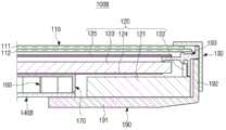
图10是示出了根据第五示例性实施例的液晶显示设备的剖视图;10 is a cross-sectional view showing a liquid crystal display device according to a fifth exemplary embodiment;
图11是图10中示出的液晶显示设备的右端部的放大剖视图。FIG. 11 is an enlarged cross-sectional view of a right end portion of the liquid crystal display device shown in FIG. 10 .
具体实施方式Detailed ways
下面参照附图来更详细地描述特定的示例性实施例。Certain exemplary embodiments are described in more detail below with reference to the accompanying drawings.
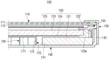
图1是示出了根据第一示例性实施例的液晶显示设备的剖视图,图2是图1中示出的液晶显示设备的右端部的放大剖视图。1 is a sectional view showing a liquid crystal display device according to a first exemplary embodiment, and FIG. 2 is an enlarged sectional view of a right end portion of the liquid crystal display device shown in FIG. 1 .
参照图1和图2,液晶显示(LCD)设备100可应用于各种液晶显示设备,更具体地讲,可应用于大尺寸显示设备,例如,55英寸或更大的电视。如图1所示,液晶显示设备100是一种平板显示设备。Referring to FIGS. 1 and 2 , a liquid crystal display (LCD)
如图2所示,液晶显示设备100包括液晶面板110、背光单元120、顶部支架130、底部支架140和中间模150。As shown in FIG. 2 , the liquid
液晶面板110是显示图像的组件,并且包括上面板111和下面板112。在上面板111和下面板112之间安置有液晶(未示出)。虽然未示出,但是前偏振滤光器和滤色器层设置在上面板111中,并且后偏振滤光器和TFT阵列设置在下面板112中。The
根据TFT阵列的开关操作,对与每个像素对应的液晶分子的排列进行调整,从而由液晶面板110显示图像。液晶面板110的操作原理是已知的,因此省略了对其的进一步解释。According to the switching operation of the TFT array, the arrangement of liquid crystal molecules corresponding to each pixel is adjusted, so that an image is displayed by the
背光单元120用来提供用于在液晶面板110上显示图像的光。因此,背光单元120包括至少一个光源印刷电路板(光源PCB)121、安装于每个光源印刷电路板121的多个光源122、安置在液晶面板110的后侧的导光板123、安置在导光板123的后侧的反射片124以及安置在液晶面板110和导光板123之间的多个光学片125。The
在本示例性实施例中,每个光源PCB121安置在盖构件170的左侧和右侧(见图1),设置在每个光源PCB中的多个光源122安置成面向导光板123的边缘表面123a。例如,光源122可以设置成LED。从光源122发出的光穿过边缘表面123a进入导光板123的内部,进入的光在设置在安置于导光板123的后侧的反射片124和导光板123的前表面或后表面中的光发射图案(未示出)的帮助下被引导到导光板123的前部,并且被引导的光在其通过光学片125变得亮度分布更加均匀之后被提供到液晶面板110。In this exemplary embodiment, each light source PCB 121 is arranged on the left and right sides of the cover member 170 (see FIG. 1 ), and the plurality of
有利的是,光源PCB121由导热率高的诸如以铝、不锈钢等为例的金属材料制成,从而由光源122产生的热被很好地传递到底部支架140,底部支架140使热消散并由此起着散热器的作用。Advantageously, the
在上文解释的背光单元120的结构仅仅是个示例,因此,根据其它示例性实施例的背光单元120的详细结构可以以各种方式进行改变。另外,背光单元120的一般结构是已知的,因此省略了对其进一步的详细解释。The structure of the
顶部支架130和底部支架140将液晶显示设备100的包括上文解释的液晶面板110和背光单元120的组件容纳在一个模块中。中间模150支撑液晶面板110和光学片125等组件,并且有助于液晶显示设备100的包封。The
底部支架140具有相对于液晶面板110和背光单元120基本正交地安置的结合部142。由于结合部142通过诸如螺钉的紧固件被紧固到顶部支架130,所以底部支架140直接结合到顶部支架130。在其它可选择的示例性实施例中,顶部支架130和底部支架140可以通过中间模150彼此结合,因而并不是彼此直接结合。即,因为顶部支架130和底部支架140中的每个独立地连接到中间模150,所以顶部支架130和底部支架140可以彼此相互连接。The
底部支架140也执行将光源122产生的热排放到外部的功能。即,底部支架140也起着用来冷却光源122的散热器的作用。为此,有利的是,底部支架140由诸如以铝、不锈钢等为示例的导热率高的金属材料制成。The
底部支架140使强度增强构件160安装到底部支架140的内表面141上。强度增强构件160被盖构件170覆盖。这里,强度增强构件160增强底部支架140,使底部支架140变得更加牢固,从而防止底部支架140的变形。通过这样的强度增强构件160,底部支架140变得能够保持良好的平坦度。The
参照图3和图4,将更详细地描述强度增强构件160和盖构件170。Referring to FIGS. 3 and 4 , the
图3是示出了设置在图1的液晶显示设备中的底部支架和安装到底部支架的组件的透视图,图4是示出了图3的拆解后的组件的透视图。3 is a perspective view showing a bottom bracket provided in the liquid crystal display device of FIG. 1 and components mounted to the bottom bracket, and FIG. 4 is a perspective view showing disassembled components of FIG. 3 .
参照图3和图4,强度增强构件160安置在底部支架140的中央部分。因此,底部支架140的内表面141分为被强度增强构件160占据的占据区域141a和没有被强度增强构件160占据的未占据区域141b。这里,在图4中,占据区域141a被表示为矩形的虚线,占据区域141a的形状和面积大小会根据强度增强构件160的形状和面积而改变。在未占据区域141b中,安装有两个光源PCB121,强度增强构件160设置在这两个光源PCB121之间。因此,在强度增强构件160的每一侧设置一个光源PCB121。注意的是,可选择地,可以有多个光源PCB121,使得强度增强构件的每一侧具有多个光源PCB。在每个光源PCB121上布置有多个光源122。Referring to FIGS. 3 and 4 , a
强度增强构件160通过例如粘结剂(诸如,热熔性粘结剂)附于底部支架140。如图4所示,强度增强构件160具有多个单元(cell)161,其中,每个单元具有六方柱的形状。因此,强度增强构件160的总体形状为蜂窝。然而,这仅仅是个示例,在其它可选择的示例性实施例中,每个单元161的形状可以变成具有其它各种形状,例如,其它的诸如四方形柱形状或圆柱形形状等的柱状形状。The
强度增强构件160由铝制成,并且有利的是,强度增强构件160可以由具有高强度的铝制成。然而,并不局限于此,因此,强度增强构件160可以由其它金属材料或诸如以塑料为示例的非金属材料制成。The
这样,具有蜂窝形状的强度增强构件160可以被安装到底部支架140,从而显著增强了底部支架140并且改善了底部支架140的强度性能。因此,可以使底部支架140因重量、外力或热等的变形最小化,所以可以保持底部支架140的良好的平坦度。因此,能够防止由液晶面板110显示的图像的品质劣化,否则将因底部支架140的这种变形而导致由液晶面板110显示的图像的品质劣化。As such, the
另外,由于强度增强构件160并没有使底部支架140的厚度增加而实现了底部支架140的强度性能的改善,并且由于通过粘结剂相对简单地使强度增强构件160附于底部支架140,所以能够改善底部支架140的强度性能同时保持低的制造成本和高的生产率。In addition, since the
即使当将液晶显示设备100应用于大尺寸显示设备(例如,55英寸或更大的电视)时,也能够通过上述强度增强构件160的方式保持底部支架140的良好的平坦度。在这种大尺寸显示设备的情况下,底部支架140的区域尺寸明显地变大,因而有利于防止底部支架140的变形并保持其良好的平坦度。Even when the liquid
盖构件170覆盖强度增强构件160,从而强度增强构件160并没有被暴露。因此,盖构件170包括覆盖强度增强构件160的上侧的上部171和覆盖强度增强构件160的边界的侧部172。例如,可以通过弯曲工艺形成侧部172。盖构件170可以由与强度增强构件160的材料相同的材料制成。因此,盖构件170可以由例如铝制成。另外,盖构件170例如通过诸如热熔性粘结剂的粘结剂附于强度增强构件160。The
由于强度增强构件160被盖构件170覆盖,所以可以防止可能存在于强度增强构件160中并且可能导致液晶显示设备100的性能劣化的污染物进入液晶显示设备100。例如,在强度增强构件160的加工或成形的过程中产生的颗粒可以作为这种污染物的示例。此外,参照图2,盖构件170还可以执行支撑放置在其上侧的诸如导光板120的组件的功能。Since the
图5是示出了根据可选择的示例性实施例的设置在图1的液晶显示设备中的强度增强构件的透视图,图6是示出了根据另一可选择的示例性实施例的设置在图1的液晶显示设备中的强度增强构件的透视图。5 is a perspective view showing a strength reinforcing member provided in the liquid crystal display device of FIG. 1 according to an alternative exemplary embodiment, and FIG. 6 is a perspective view showing an arrangement according to another alternative exemplary embodiment. A perspective view of a strength reinforcing member in the liquid crystal display device of FIG. 1 .
参照图5,可选择的强度增强构件160A具有波纹的形状。更具体地讲,强度增强构件160A具有凸出部分163和凹入部分164轮流地重复的结构。这里,凸出部分163和凹入部分164沿着强度增强构件160A的宽度方向或纵向方向延伸。即,在两个凸出部分163之间安置一个凹入部分164,在两个凹入部分163之间安置一个凸出部分163。Referring to FIG. 5, an optional strength enhancement member 160A has a corrugated shape. More specifically, the strength reinforcing member 160A has a structure in which a convex portion 163 and a concave portion 164 are alternately repeated. Here, the convex portion 163 and the concave portion 164 extend along the width direction or the longitudinal direction of the strength reinforcing member 160A. That is, one concave portion 164 is disposed between two convex portions 163 , and one convex portion 163 is disposed between two concave portions 163 .
参照图6,另一种可选择的强度增强构件160B具有蛋托的形状。更具体地讲,强度增强构件160B具有按二维阵列规则地重复的多个凸出部分165和多个凹入部分166,在四个凸出部分165之间安置一个凹入部分166,在四个凹入部分166之间安置一个凸出部分165。Referring to Figure 6, another optional
在本公开中,介绍了具有不同形状的三种强度增强构件160、160A、160B,但是可以使用具有其它形状的其它强度增强构件,只要这些强度增强构件有助于改善底部支架140的强度性能即可。In this disclosure, three
图7是与图2相似的视图,其示出了根据第二示例性实施例的液晶显示设备的剖视图。FIG. 7 is a view similar to FIG. 2 showing a cross-sectional view of a liquid crystal display device according to a second exemplary embodiment.
图7中示出的液晶显示设备100'的构造与在前述图1中示出的液晶显示设备100的构造相似。然而,对于前述液晶显示设备100的情形,强度增强构件160直接附于底部支架140,而对于液晶显示设备100'的情形,不同之处在于强度增强构件160通过附加的下侧盖构件175安装到底部支架140。The configuration of the liquid crystal display device 100' shown in FIG. 7 is similar to that of the liquid
这样,除了包括上侧盖构件170之外,液晶显示设备100'还包括下侧盖构件175,上侧盖构件170和下侧盖构件175围绕强度增强构件160。在这种情况下,下侧盖构件175、强度增强构件160和上侧盖构件170可以顺序地附于底部支架140上,但是下侧盖构件175、强度增强构件160和上侧盖构件170可以首先相互独立地彼此粘合以形成一个强度增强元件101,然后通过使用诸如胶带的粘结剂或其它这样的粘合方法同时粘合到底部支架140。首先形成一个强度增强元件101具有简化液晶显示设备100'的制造工艺的优点。As such, the liquid
图8是与图2相似的视图,其示出了根据第三示例性实施例的液晶显示设备的剖视图。FIG. 8 is a view similar to FIG. 2 showing a cross-sectional view of a liquid crystal display device according to a third exemplary embodiment.
参照图8,可选择的液晶显示设备100A与前述图1中示出的液晶显示设备100的构造相似。尤其是,可选择的液晶显示设备100A与图1的液晶显示设备100的相似之处在于用于强度增强的强度增强构件160安装到底部支架140A。Referring to FIG. 8 , an alternative liquid
液晶显示设备100A与前述液晶显示设备100的不同之处在于:液晶显示设备100A还包括安置在光源PCB121和底部支架140A之间的散热器180。散热器180由例如铝的高导热率材料制成,以将光源122产生的热更有效地传递到底部支架140A。The difference between the liquid
这种散热器180包括支撑光源PCB121的本体部181和与本体部181基本正交的结合部182。结合部182通过紧固件被紧固到顶部支架130,从而直接结合到顶部支架130。在其它可选择的示例性实施例中,可以可选择地将散热器180直接结合到中间模150。Such a
图9是与图2相似的视图,其示出了根据第四示例性实施例的液晶显示设备的剖视图。FIG. 9 is a view similar to FIG. 2 showing a cross-sectional view of a liquid crystal display device according to a fourth exemplary embodiment.
参照图9,另一种可选择的液晶显示设备100B也与图1中示出的上述液晶显示设备100相似。具体地讲,液晶显示设备100B与图1的液晶显示设备100的相似之处在于:用于强度增强的强度增强构件160安装到底部支架140B。Referring to FIG. 9 , another optional liquid
液晶显示设备100B与前述液晶显示设备100的不同之处在于:液晶显示设备100B还包括安置在底部支架140B的后侧的散热器190。散热器190由例如铝的高导热率材料制成,以将光源122产生的更有效地传递到外部。The difference between the liquid
这种散热器190包括本体部191和结合部192。本体部191不仅支撑光源PCB121,而且支撑底部支架140B。由于与其它示例性实施例相比,光源PCB121并不是由底部支架140B直接支撑,所以可以减小底部支架140B的大小(例如,在图1中从右到左方向上的宽度,或者面积等)。例如,可以使底部支架140B的宽度减小到与盖构件170的宽度相同。此外,由于结合部192通过诸如螺钉的紧固件(未示出)被紧固到顶部支架130,所以可以将散热器190直接结合到顶部支架130。在可选择的示例性实施例中,散热器190可以可选择地被紧固到中间模150。This
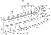
图10是示出了根据第五示例性实施例的液晶显示设备的剖视图,图11是图10中示出的液晶显示设备的右端部的放大剖视图。10 is a sectional view showing a liquid crystal display device according to a fifth exemplary embodiment, and FIG. 11 is an enlarged sectional view of a right end portion of the liquid crystal display device shown in FIG. 10 .
参照图10和图11,与前述的液晶显示设备不一样,根据第五示例性实施例的液晶显示设备200是曲面显示设备。Referring to FIGS. 10 and 11 , unlike the aforementioned liquid crystal display device, a liquid
与根据第一示例性实施例的液晶显示设备100(见图1和图2)相比,液晶显示设备200的液晶面板110、背光单元120、顶部支架130、底部支架140、中间模150和强度增强构件160的详细构造按与前述液晶显示设备100的液晶面板110、背光单元120、顶部支架130、底部支架140、中间模150和强度增强构件160的详细构造的方式基本相同的方式进行设置,但是由于液晶显示设备200是具有曲率的曲面显示器,所以,液晶显示设备200的液晶面板110、背光单元120、顶部支架130、底部支架140、中间模150和强度增强构件160被形成为符合这种曲率。Compared with the liquid crystal display device 100 (see FIGS. 1 and 2 ) according to the first exemplary embodiment, the
如上所讨论的,在第五示例性实施例中,液晶显示设备200的底部支架140也被形成为符合这种曲率。因此,底部支架140的优点在于具有良好的强度特性和性能而保持了该曲率。As discussed above, in the fifth exemplary embodiment, the
可以应用各种方法来制造弯曲形状的液晶显示设备200。例如,可以使用这样的制造方法:在制造弯曲表面形状的底部支架140之后,将非弯曲表面形状的顶部支架130装配到底部支架140,从而使诸如顶部支架130等的组件符合底部支架140的曲率。在这种方法中,如果底部支架140的强度不足,则可能会难以保持液晶显示设备200的弯曲表面形状,因此底部支架140的良好的强度特性是有益的。Various methods may be applied to manufacture the curved-shaped liquid
因此,将蜂窝形状的强度增强构件160安装到底部支架140的内表面141,用来增强底部支架140的强度。如前所述的,可以显著地增强附着有蜂窝形状的强度增强构件160的底部支架140的强度,因此,即使当重量、外力或热等作用于液晶显示设备200时,液晶显示设备200也可以稳定地保持初始曲率。因此,能够防止由液晶显示设备200提供的图像的品质因底部支架140从最初的制造曲率的变形而劣化。Accordingly, the honeycomb-shaped
第五示例性实施例被描述为具有与强度增强构件160的形状一样的呈蜂窝形状的强度增强构件160,但是如前所述的,也可以应用波纹形状或蛋托形状等作为强度增强构件160的可选择的形状。The fifth exemplary embodiment has been described as having the
如前所述的,根据本公开,可以将强度增强构件安装到底部支架,以显著地改善底部支架的强度,从而使底部支架因重量、外力、热等而引起的变形最小化。因此,在将本公开应用于平板显示设备的情况下,能够保持平板显示设备的良好的平坦度;在将本公开应用于曲面显示设备的情况下,能够具有稳定性地保持初始曲率。因此,能够防止由底部支架的过度变形导致的显示设备提供的图像的品质的劣化。As previously described, according to the present disclosure, a strength reinforcing member may be mounted to the bottom bracket to significantly improve the strength of the bottom bracket, thereby minimizing deformation of the bottom bracket due to weight, external force, heat, and the like. Therefore, when the present disclosure is applied to a flat display device, good flatness of the flat display device can be maintained; when the present disclosure is applied to a curved display device, the initial curvature can be stably maintained. Accordingly, it is possible to prevent deterioration in the quality of an image provided by the display device caused by excessive deformation of the bottom bracket.
在例如55英寸或更大的电视的大尺寸液晶显示设备的情况下,也使底部支架的面积增大,因此变得有利于防止底部支架的变形。因此,根据本公开的液晶显示设备可以尤为有利地应用于这种大尺寸显示设备。In the case of a large-sized liquid crystal display device such as a television of 55 inches or more, the area of the bottom bracket is also increased, and thus it becomes advantageous to prevent deformation of the bottom bracket. Therefore, the liquid crystal display device according to the present disclosure can be particularly advantageously applied to such a large-sized display device.
虽然已经示出和描述了本发明的一些实施例,但是本领域技术人员应当理解,在不脱离发明构思的原理和精神的情况下可以对这些示例性实施例做出改变,发明构思的范围限定在权利要求及其等同物中。Although some embodiments of the present invention have been shown and described, it should be understood by those skilled in the art that changes may be made to these exemplary embodiments without departing from the principles and spirit of the inventive concept, and the scope of the inventive concept is limited. in the claims and their equivalents.
Claims (15)
Applications Claiming Priority (4)
| Application Number | Priority Date | Filing Date | Title |
|---|---|---|---|
| KR20120056184 | 2012-05-25 | ||
| KR10-2012-0056184 | 2012-05-25 | ||
| KR10-2012-0127641 | 2012-11-12 | ||
| KR1020120127641AKR102013932B1 (en) | 2012-05-25 | 2012-11-12 | Liquid crystal display apparatus |
Publications (2)
| Publication Number | Publication Date |
|---|---|
| CN103424898Atrue CN103424898A (en) | 2013-12-04 |
| CN103424898B CN103424898B (en) | 2018-06-01 |
Family
ID=
Cited By (5)
| Publication number | Priority date | Publication date | Assignee | Title |
|---|---|---|---|---|
| CN103838036A (en)* | 2014-03-21 | 2014-06-04 | 深圳市华星光电技术有限公司 | Curved-surface LCD device |
| CN104730764A (en)* | 2013-12-18 | 2015-06-24 | 三星电子株式会社 | Display device |
| CN104882070A (en)* | 2014-02-28 | 2015-09-02 | 三星电子株式会社 | Display apparatus |
| CN105549243A (en)* | 2014-10-27 | 2016-05-04 | 三星电子株式会社 | Display apparatus |
| CN111354262A (en)* | 2018-12-20 | 2020-06-30 | Lg电子株式会社 | Display device |
Citations (7)
| Publication number | Priority date | Publication date | Assignee | Title |
|---|---|---|---|---|
| JP2008276035A (en)* | 2007-05-02 | 2008-11-13 | Seiko Epson Corp | Electronic equipment, display device and protective cover |
| JP2008288047A (en)* | 2007-05-17 | 2008-11-27 | Sharp Corp | Backlight device and display device |
| CN101657674A (en)* | 2007-03-09 | 2010-02-24 | 夏普株式会社 | Lighting device for display device and display device |
| US20110007236A1 (en)* | 2009-07-09 | 2011-01-13 | Nam-Su Kim | Liquid crystal display device |
| WO2011024254A1 (en)* | 2009-08-25 | 2011-03-03 | 富士通株式会社 | Casing structure, electronic device and method of manufacturing same |
| CN102042542A (en)* | 2009-10-19 | 2011-05-04 | 三星电子株式会社 | Backlight assembly and liquid crystal display with same |
| CN102171504A (en)* | 2008-10-01 | 2011-08-31 | 夏普株式会社 | Lighting devices, display devices and television receivers |
Patent Citations (7)
| Publication number | Priority date | Publication date | Assignee | Title |
|---|---|---|---|---|
| CN101657674A (en)* | 2007-03-09 | 2010-02-24 | 夏普株式会社 | Lighting device for display device and display device |
| JP2008276035A (en)* | 2007-05-02 | 2008-11-13 | Seiko Epson Corp | Electronic equipment, display device and protective cover |
| JP2008288047A (en)* | 2007-05-17 | 2008-11-27 | Sharp Corp | Backlight device and display device |
| CN102171504A (en)* | 2008-10-01 | 2011-08-31 | 夏普株式会社 | Lighting devices, display devices and television receivers |
| US20110007236A1 (en)* | 2009-07-09 | 2011-01-13 | Nam-Su Kim | Liquid crystal display device |
| WO2011024254A1 (en)* | 2009-08-25 | 2011-03-03 | 富士通株式会社 | Casing structure, electronic device and method of manufacturing same |
| CN102042542A (en)* | 2009-10-19 | 2011-05-04 | 三星电子株式会社 | Backlight assembly and liquid crystal display with same |
Cited By (13)
| Publication number | Priority date | Publication date | Assignee | Title |
|---|---|---|---|---|
| CN104730764A (en)* | 2013-12-18 | 2015-06-24 | 三星电子株式会社 | Display device |
| CN104730764B (en)* | 2013-12-18 | 2019-07-12 | 三星电子株式会社 | Display device |
| CN104882070B (en)* | 2014-02-28 | 2019-07-05 | 三星电子株式会社 | Display device |
| CN104882070A (en)* | 2014-02-28 | 2015-09-02 | 三星电子株式会社 | Display apparatus |
| US10366650B2 (en) | 2014-02-28 | 2019-07-30 | Samsung Electronics Co., Ltd. | Display apparatus, chassis thereof, and a manufacturing method thereof |
| WO2015139342A1 (en)* | 2014-03-21 | 2015-09-24 | 深圳市华星光电技术有限公司 | Curved liquid crystal display device |
| CN103838036A (en)* | 2014-03-21 | 2014-06-04 | 深圳市华星光电技术有限公司 | Curved-surface LCD device |
| CN105549243A (en)* | 2014-10-27 | 2016-05-04 | 三星电子株式会社 | Display apparatus |
| CN111354262A (en)* | 2018-12-20 | 2020-06-30 | Lg电子株式会社 | Display device |
| CN111354262B (en)* | 2018-12-20 | 2022-04-08 | Lg电子株式会社 | Display device |
| US11360514B2 (en) | 2018-12-20 | 2022-06-14 | Lg Electronics Inc. | Display device |
| US11755071B2 (en) | 2018-12-20 | 2023-09-12 | Lg Electronics Inc. | Display device |
| US12019478B2 (en) | 2018-12-20 | 2024-06-25 | Lg Electronics Inc. | Display device |
Also Published As
| Publication number | Publication date |
|---|---|
| US9310647B2 (en) | 2016-04-12 |
| US20130314638A1 (en) | 2013-11-28 |
| EP2667247B1 (en) | 2014-12-03 |
| JP6154195B2 (en) | 2017-06-28 |
| JP2013246442A (en) | 2013-12-09 |
| EP2667247A1 (en) | 2013-11-27 |
| WO2013176399A1 (en) | 2013-11-28 |
Similar Documents
| Publication | Publication Date | Title |
|---|---|---|
| US9310647B2 (en) | Liquid crystal display apparatus having reinforcement | |
| US10798832B2 (en) | Display apparatus | |
| US8634042B2 (en) | Liquid crystal display with a plurality of liquid crystal display modules | |
| US9433112B2 (en) | Display apparatus | |
| CN103810942B (en) | The display device of bending | |
| US9826654B2 (en) | Display | |
| KR102013932B1 (en) | Liquid crystal display apparatus | |
| EP2713200B1 (en) | Liquid crystal display device | |
| US20110090426A1 (en) | Backlight assembly and liquid crystal display having the same | |
| US9563078B2 (en) | Frame for display device and display device having the same | |
| US9810935B2 (en) | Display device | |
| US9798177B2 (en) | Display apparatus including touch panel fixing a display panel to a backlight unit | |
| US9470379B2 (en) | Display apparatus | |
| US20060104067A1 (en) | Heat-dissipating method and structure of backlight module of display device | |
| CN110121674A (en) | Panel module and display device including panel module | |
| CN103969886A (en) | Display apparatus | |
| US8870440B2 (en) | Back light module and liquid crystal display device having the same | |
| CN103424898B (en) | Liquid crystal display | |
| US8804063B2 (en) | Image display device | |
| KR101333267B1 (en) | Liquid crystal display device | |
| US20190187512A1 (en) | Display unit and display apparatus having the same | |
| CN104346998A (en) | Display apparatus | |
| CN101266353A (en) | Liquid crystal display and its backlight module | |
| KR20080067743A (en) | Back light assembly and display device having same | |
| KR20070071299A (en) | LCD Display |
Legal Events
| Date | Code | Title | Description |
|---|---|---|---|
| C06 | Publication | ||
| PB01 | Publication | ||
| C10 | Entry into substantive examination | ||
| SE01 | Entry into force of request for substantive examination | ||
| GR01 | Patent grant | ||
| GR01 | Patent grant |