CN103424126A - System and method for verifying visual autonomous landing simulation of unmanned aerial vehicle - Google Patents
System and method for verifying visual autonomous landing simulation of unmanned aerial vehicleDownload PDFInfo
- Publication number
- CN103424126A CN103424126ACN2013103500480ACN201310350048ACN103424126ACN 103424126 ACN103424126 ACN 103424126ACN 2013103500480 ACN2013103500480 ACN 2013103500480ACN 201310350048 ACN201310350048 ACN 201310350048ACN 103424126 ACN103424126 ACN 103424126A
- Authority
- CN
- China
- Prior art keywords
- landing
- uav
- module
- coordinate system
- camera
- Prior art date
- Legal status (The legal status is an assumption and is not a legal conclusion. Google has not performed a legal analysis and makes no representation as to the accuracy of the status listed.)
- Granted
Links
- 238000004088simulationMethods0.000titleclaimsabstractdescription51
- 230000000007visual effectEffects0.000titleclaimsabstractdescription45
- 238000000034methodMethods0.000titleclaimsabstractdescription42
- 238000012795verificationMethods0.000claimsabstractdescription36
- 238000004422calculation algorithmMethods0.000claimsabstractdescription21
- 239000011159matrix materialSubstances0.000claimsdescription74
- 238000001514detection methodMethods0.000claimsdescription36
- 238000013519translationMethods0.000claimsdescription27
- 239000000284extractSubstances0.000claimsdescription13
- 238000012545processingMethods0.000claimsdescription11
- 230000000717retained effectEffects0.000claimsdescription8
- 238000013461designMethods0.000claimsdescription4
- 238000012546transferMethods0.000claimsdescription4
- 238000000354decomposition reactionMethods0.000claimsdescription3
- 230000011218segmentationEffects0.000claimsdescription3
- 230000009466transformationEffects0.000claimsdescription3
- 238000012800visualizationMethods0.000abstractdescription3
- 238000010586diagramMethods0.000description4
- 238000012360testing methodMethods0.000description3
- 238000004364calculation methodMethods0.000description2
- 238000011161developmentMethods0.000description2
- 230000018109developmental processEffects0.000description2
- 230000000694effectsEffects0.000description2
- 238000000605extractionMethods0.000description1
Images


Landscapes
- Image Analysis (AREA)
Abstract
Translated fromChineseDescription
Translated fromChinese技术领域technical field
本发明涉及一种无人机视觉自主着陆仿真验证系统及方法,能够在真实地形下对无人机自主着陆视觉算法进行仿真验证,利用虚拟现实和可视化技术,构建了机载摄像机和着陆地标,通过多通道显示整个着陆阶段和摄像机拍摄的图像并实时计算和输出视觉着陆导航所需数据。The present invention relates to a UAV visual autonomous landing simulation verification system and method, which can simulate and verify the UAV autonomous landing vision algorithm under real terrain, and use virtual reality and visualization technology to construct an airborne camera and landing landmarks, Display the entire landing phase and the images captured by the camera through multiple channels, and calculate and output the data required for visual landing navigation in real time.
背景技术Background technique
在整个无人机的飞行导航过程中,安全着陆是一个非常重要的阶段。在现有的着陆导航方式中,惯性导航由于需要通过积分运算来得到飞行器大概位置和速度信息,使得误差会随着时间的推移不断增加;GPS卫星导航容易受到电子干扰;地面控制导航则受控于人类因素。这些问题都可能导致着陆的失败。Safe landing is a very important stage in the flight and navigation process of UAV. In the existing landing navigation method, inertial navigation needs to obtain the approximate position and speed information of the aircraft through integral calculation, so that the error will continue to increase over time; GPS satellite navigation is susceptible to electronic interference; ground control navigation is controlled on human factors. These problems may lead to the failure of the landing.
传统的载人机着陆时,飞行员可以依靠视觉所提供的信息来定位直升机空间位置和直升机相对于着陆平台的旋转关系。而无人机一般通过机载传感器提供这些信息,因此可以考虑使用计算机视觉技术模拟飞行员的视野,并通过视觉算法对机载摄像机所获取的实时图像进行处理和分析,估计出无人机相对于着陆地标的位置与姿态信息,进而完成自主着陆。由于视觉着陆导航技术尚不成熟,需要进行大量的飞行试验,因此有必要建立一个仿真验证系统完成在实验室环境下对视觉着陆算法的验证。现有的验证方法中,要么是对已知位姿值的单帧图像处理进行验证,而无人机自主着陆是一个动态过程,单帧图像的意义不大;要么使用MATLAB模拟无人机自主着陆过程进行验证,该方法一定程度上解决了无人机自主着陆动态过程展示的问题,但其对无人机及飞行环境的呈现过于简单,仿真过程往往缺乏沉浸式的真实感;基于此,如何通过先进的虚拟现实技术以及计算机视觉技术构建一个可视化良好的无人机自主着陆仿真验证系统是急需解决的问题,其中视景仿真软件与视觉着陆算法如何结合是问题的关键所在。When a traditional manned aircraft lands, the pilot can rely on the information provided by the vision to locate the spatial position of the helicopter and the rotation relationship of the helicopter relative to the landing platform. UAVs generally provide this information through airborne sensors, so computer vision technology can be considered to simulate the pilot's field of vision, and the real-time images acquired by the airborne camera are processed and analyzed through visual algorithms to estimate the relative distance between the UAV and the aircraft. The position and attitude information of the landing landmark, and then complete the autonomous landing. Since the visual landing navigation technology is still immature and a large number of flight tests are required, it is necessary to establish a simulation verification system to complete the verification of the visual landing algorithm in the laboratory environment. In the existing verification methods, either the single-frame image processing of the known pose value is verified, and the autonomous landing of the UAV is a dynamic process, and the single-frame image is of little significance; or use MATLAB to simulate the autonomous UAV. The landing process is verified. This method solves the problem of displaying the dynamic process of the UAV’s autonomous landing to a certain extent, but its presentation of the UAV and the flight environment is too simple, and the simulation process often lacks an immersive sense of reality. Based on this, How to build a well-visualized UAV autonomous landing simulation verification system through advanced virtual reality technology and computer vision technology is an urgent problem to be solved, and how to combine the visual simulation software with the visual landing algorithm is the key to the problem.
发明内容Contents of the invention
本发明的目的是提供一种无人机视觉自主着陆仿真验证系统及方法,使用VegaPrime软件和视觉算法结合,在真实地形中对无人机自主着陆的视觉算法进行验证,能够展示整个着陆阶段并实时的计算和显示视觉着陆导航所需数据,可以有效的降低开发成本,减少飞行试验数量,缩短视觉导航技术的研发周期。The purpose of the present invention is to provide a UAV visual autonomous landing simulation verification system and method, using VegaPrime software combined with visual algorithms to verify the visual algorithm of UAV autonomous landing in real terrain, which can display the entire landing stage and Real-time calculation and display of data required for visual landing and navigation can effectively reduce development costs, reduce the number of flight tests, and shorten the development cycle of visual navigation technology.
本发明的技术方案是:一种无人机视觉自主着陆仿真验证系统,其特征是:至少包括VegaPrime模块、着陆地标检测模块、无人机位姿估计模块,VegaPrime模块用于展示无人机着陆的视景,着陆地标检测模块用于对当前帧图像中进行图像处理,使用DP多边形拟合算法对着陆地标进行多边形拟合并提取角点,对所得角点重新排序与着陆地标对应后将结果传至无人机位姿估计模块;无人机位姿估计模块用于利用Courtney的方法得到无人机相对于着陆地标的旋转矩阵和平移矩阵,并通过旋转矩阵与欧拉角的关系得到无人机的三个姿态角,实时估计无人机位姿。The technical solution of the present invention is: a UAV visual autonomous landing simulation verification system, which is characterized in that it includes at least a VegaPrime module, a landing landmark detection module, and a UAV pose estimation module, and the VegaPrime module is used to display UAV landing The landing landmark detection module is used to perform image processing on the current frame image, use the DP polygon fitting algorithm to perform polygon fitting on the landing landmark and extract the corner points, reorder the obtained corner points to correspond to the landing landmarks, and then compare the results Passed to the UAV pose estimation module; the UAV pose estimation module is used to obtain the rotation matrix and translation matrix of the UAV relative to the landing landmark by using Courtney's method, and obtain the infinite The three attitude angles of the man-machine can estimate the UAV pose in real time.
所述VegaPrime模块至少包括无人机模块、着陆地标模块、摄像机模块、显示模块,无人机模块中使用了Vegaprime模型库中的阿帕奇直升机,并在直升机中加入了前视摄像机和着陆用摄像机;着陆地标模块中使用Creator建模工具建立了一个长5米,宽3米的H型地标;正视地标时,左上角角点定为地标坐标系原点,坐标为(0,0),其余各点顺时针排序,坐标依次为(1,0)、(1,2)、(2,2)、(2,0)、(3,0)、(3,5)、(2,5)(2,3)、(1,3)、(1,5)、(0,5);摄像机模块为着陆用摄像机,其位置固定于无人机中心,垂直向下拍摄,根据一般机载摄像头视场角范围设置该观察者的水平FOV为30度,垂直FOV为20度,拍摄视频大小为360*240像素;通过无人机姿态估计算法反解求得模拟摄像机的内参矩阵,通过配置,将无人机位置调整到着陆地标原点正上方,且3个姿态角均为零,此时无人机相对于着陆地标的旋转矩阵R为单位阵,平移矩阵t=(0 0 h)T;在不同高度h下截取摄像头所拍摄到的地标图像,并通过图像处理得到图像中的12个角点像素坐标,分别将12个角点的物理坐标和像素坐标以及旋转矩阵、平移矩阵带入公式:The VegaPrime module at least includes a UAV module, a landing landmark module, a camera module, and a display module. The UAV module uses the Apache helicopter in the Vegaprime model library, and adds a forward-looking camera and a landing device to the helicopter. Camera; use the Creator modeling tool in the landing landmark module to create an H-shaped landmark with a length of 5 meters and a width of 3 meters; The points are sorted clockwise, and the coordinates are (1,0), (1,2), (2,2), (2,0), (3,0), (3,5), (2,5) (2,3), (1,3), (1,5), (0,5); the camera module is a camera for landing, its position is fixed in the center of the UAV, and it shoots vertically downwards, according to the general airborne camera The field of view range sets the horizontal FOV of the observer to 30 degrees, the vertical FOV to 20 degrees, and the size of the shooting video to 360*240 pixels; the internal parameter matrix of the analog camera is obtained through the reverse solution of the UAV attitude estimation algorithm, and through configuration, Adjust the position of the drone to just above the origin of the landing mark, and the three attitude angles are all zero. At this time, the rotation matrix R of the drone relative to the landing mark is a unit matrix, and the translation matrix t=(0 0 h)T ; Intercept the landmark images captured by the camera at different heights h, and obtain the pixel coordinates of 12 corner points in the image through image processing, respectively bring the physical coordinates and pixel coordinates of the 12 corner points, as well as the rotation matrix and translation matrix into the formula :
解此方程组便可求得摄像机内参矩阵A,其中
所述着陆地标检测模块,至少包括角点检测、角点排序,角点检测首先对显示模块的摄像机图像进行灰度化处理,利用阈值分割的方法分离出地标区域,然后经过轮廓提取,并保留单连通闭合且长度为图像周长的0.5倍到1.5倍的轮廓得到地标的轮廓,对该轮廓进行DP多边形拟合后提取角点,保留角点像素坐标;角点排序用于对角点检测所得到的角点进行排序,角点检测所保留的角点顺序为像素坐标系下v坐标最小的点为初始点,其余各点顺时针依次排列;当角点检测所得图像角点a、b两点之间距离小于a、l两点之间距离时角点检测所得排序即为正确顺序,当角点检测所得图像角点a、b两点之间距离大于a、l两点之间距离时需要对所有点重新排序,遍历轮廓,取图像像素坐标系下u坐标最小的点为初始点,其余各点按顺时针依次排序;角点排序所得图像角点最终排序结果和物理坐标系下地标各角点一一对应。The landing landmark detection module at least includes corner detection and corner sorting. The corner detection first performs gray-scale processing on the camera image of the display module, and uses the method of threshold segmentation to separate the landmark area, and then extracts the outline, and retains A contour that is simply connected and closed and whose length is 0.5 to 1.5 times the perimeter of the image is used to obtain the contour of the landmark. After the contour is fitted with DP polygons, the corner points are extracted, and the pixel coordinates of the corner points are retained; the corner point sorting is used for corner point detection The obtained corner points are sorted, and the order of the corner points retained by the corner point detection is that the point with the smallest v coordinate in the pixel coordinate system is the initial point, and the other points are arranged in a clockwise order; When the distance between the two points is less than the distance between the two points a and l, the sorting obtained by the corner point detection is the correct order. When the distance between the two points a and b of the image corner points detected by the corner point is greater than the distance between the two points a and l It is necessary to reorder all the points, traverse the contour, take the point with the smallest u coordinate in the image pixel coordinate system as the initial point, and the rest of the points are sorted clockwise; The corners of the landmarks correspond one by one.
所述无人机位姿估计模块,至少包括姿态估计、位置估计,姿态估计利用Courtney的方法,已知提前求得的摄像机内参矩阵A、12个地标角点物理坐标(xi,yi)和图像像素坐标(ui,vi),并带入公式:The pose estimation module of the UAV includes at least attitude estimation and position estimation. The attitude estimation utilizes Courtney's method, and the camera internal reference matrix A obtained in advance and the physical coordinates (xi, yi ) of 12 landmark corners are known. and image pixel coordinates (ui , vi ), and put into the formula:
得到一个超定方程组,通过SVD奇异值分解法解此超定方程组得到摄像机坐标系相对于着陆地标坐标系的旋转矩阵R和平移矩阵t,然后由欧拉角与旋转矩阵的关系可得:Obtain an overdetermined equation group, solve this overdetermined equation group by SVD singular value decomposition method to obtain the rotation matrix R and translation matrix t of the camera coordinate system relative to the landing landmark coordinate system, and then the relationship between the Euler angle and the rotation matrix can be obtained :
式中,无人机的俯仰角θ、滚转角φ、偏航角ψ分别为θ=arcsinr31,φ=arctan(-r32/r33),ψ=arctan(-r21/r11);位置估计(11)用于计算无人机所处位置,已知着陆地标的原点在VegaPrime坐标系中的坐标为(x,y,z)和姿态估计(10)所求得的平移向量(tx,ty,tz),由坐标系转关关系知无人机位置为(x-tx,y+ty,z+tz);OvXvYvZv为VegaPrime坐标系,OuXuYuZu为无人机坐标系,OcXcYcZc为摄像机坐标系,OwXwYwZw为着陆地标坐标系,uv为图像像素坐标系,其中VegaPrime坐标系与着陆地标坐标系X轴平行同向,Y、Z轴平行反向,摄像机坐标系与无人机坐标系原点始终重合且任何时间不存在旋转和平移;在无人机姿态角为0时,摄像机坐标系与着陆地标坐标系三轴平行同向,定义摄像机坐标系X轴绕着陆地标坐标系X轴转过的角度θ为俯仰角且逆时针为正,摄像机坐标系Y轴绕着陆地标坐标系Y轴转过的角度φ为滚转角且逆时针为正,摄像机坐标系Z轴绕着陆地标坐标系Z轴转过的角度ψ为偏航角且逆时针为正。In the formula, the pitch angle θ, roll angle φ, and yaw angle ψ of the UAV are respectively θ=arcsinr31 , φ=arctan(-r32 /r33 ), ψ=arctan(-r21 /r11 ); The position estimation (11) is used to calculate the position of the UAV, and the coordinates of the origin of the known landing landmark in the VegaPrime coordinate system are (x, y, z) and the translation vector (tx , ty , tz ), the position of the UAV is known from the coordinate system transfer relationship as (xtx ,y+ty ,z+tz ); Ov Xv Yv Zv is the VegaPrime coordinate system, Ou Xu Yu Zu is the UAV coordinate system, Oc Xc Yc Zc is the camera coordinate system, Ow Xw Yw Zw is the landing landmark coordinate system, uv is the image pixel coordinate system, where VegaPrime The coordinate system is parallel to the X axis of the landing landmark coordinate system, and the Y and Z axes are parallel and opposite. The origin of the camera coordinate system and the UAV coordinate system always coincide and there is no rotation and translation at any time; the attitude angle of the UAV is 0 , the camera coordinate system is parallel to the three axes of the landing landmark coordinate system in the same direction. Define the angle θ that the X axis of the camera coordinate system rotates around the X axis of the landing landmark coordinate system is the pitch angle and is positive counterclockwise, and the Y axis of the camera coordinate system revolves around the landing The angle φ rotated by the Y axis of the landmark coordinate system is the roll angle and is positive counterclockwise. The angle ψ that the Z axis of the camera coordinate system rotates around the Z axis of the landmark coordinate system is the yaw angle and is positive counterclockwise.
所述的一种无人机视觉自主着陆仿真验证系统,还包括对摄像机模块和无人机模块进行模块配置数据初始化模块,初始化模块将摄像机模块内参矩阵与着陆地标角点物理坐标传送至姿态估计;摄像机模块拍摄地标图像并发送图像数据到角点检测,同时通过多窗口显示将摄像机模块所拍摄到画面呈现在屏幕上;角点检测对摄像机模块传送的图像数据进行图像处理提取着陆地标角点像素坐标将结果交由角点排序;角点排序对所得到着陆地标角点进行排序,与物理坐标系下着陆地标各角点一一对应并将角点序列传送至姿态估计;姿态估计使用摄像机内参矩阵、着陆地标角点物理坐标和着陆地标角点像素坐标计算摄像机坐标系相对于着陆地标坐标系的旋转矩阵R和平移矩阵t,并利用欧拉角与旋转矩阵关系得到无人机姿态估计值;位置估计使用姿态估计所计算得到的平移矩阵和系统坐标系转换关系计算得到无人机位置估计值;最后显示模块对由无人机模块传送的位姿真实值和由姿态估计、位置估计传送的位姿估计值进行对比显示。The described a kind of unmanned aerial vehicle vision autonomous landing simulation verification system also includes module configuration data initialization module for the camera module and the UAV module, and the initialization module transmits the internal parameter matrix of the camera module and the physical coordinates of the corner points of the landing landmarks to the attitude estimation ;The camera module captures landmark images and sends image data to corner detection, and at the same time presents the pictures captured by the camera module on the screen through multi-window display; corner detection performs image processing on the image data transmitted by the camera module to extract the corner points of the landing landmarks The pixel coordinates hand over the results to the corner sorting; the corner sorting sorts the obtained landing landmark corners, which correspond to each corner of the landing landmark in the physical coordinate system and transmit the corner sequence to the attitude estimation; the attitude estimation uses the camera Calculate the rotation matrix R and translation matrix t of the camera coordinate system relative to the landing landmark coordinate system with the internal reference matrix, the physical coordinates of the corner points of the landing marks and the pixel coordinates of the corner points of the landing marks, and use the relationship between the Euler angle and the rotation matrix to obtain the attitude estimation of the UAV value; the position estimate uses the translation matrix calculated by the attitude estimation and the transformation relationship of the system coordinate system to calculate the estimated value of the position of the UAV; finally, the display module compares the real value of the pose transmitted by the UAV module with the attitude estimation, position estimation The transmitted pose estimates are displayed for comparison.
一种无人机视觉自主着陆仿真验证方法,至少包括如下步骤:A method for simulation and verification of unmanned aerial vehicle vision autonomous landing, at least including the following steps:
步骤501:开始无人机自主着陆视觉导航仿真验证过程;Step 501: start the simulation verification process of the drone's autonomous landing visual navigation;
步骤502:载入acf配置文件,包括地形、无人机模型、着陆地标模型;Step 502: Load the acf configuration file, including terrain, UAV model, and landing landmark model;
步骤503:初始化VegaPrime各模块,初始化摄像机模块内参矩阵,载入着陆地标角点物理坐标,地形场景渲染;Step 503: Initialize each module of VegaPrime, initialize the internal reference matrix of the camera module, load the physical coordinates of the corner points of the landing landmarks, and render the terrain scene;
步骤504:基于系统时间控制无人机飞行,并提取无人机位姿值传至步骤513;Step 504: Control the flight of the drone based on the system time, and extract the pose value of the drone and send it to
步骤505:通过系统时间判断无人机是否到达着陆地标上空,若是则执行步骤506,否则执行步骤504,继续控制飞行;Step 505: judge whether the UAV has reached the sky above the landing mark by the system time, if so, execute
步骤506:获取摄像机拍摄的实时图像数据;Step 506: Obtain the real-time image data captured by the camera;
步骤507:通过阈值分割,轮廓提取,并保留单连通闭合且长度为图像周长的0.5倍到1.5倍的轮廓得到地标的轮廓;Step 507: Obtain the outline of the landmark by thresholding, extracting the outline, and retaining a single-connected closed outline whose length is 0.5 to 1.5 times the perimeter of the image;
步骤508:对步骤507获得的地标轮廓使用DP算法进行多边形拟合;Step 508: use the DP algorithm to perform polygon fitting on the landmark outline obtained in
步骤509:对步骤508的拟合结果提取角点,结果为像素坐标系下y坐标最小的点为初始点,其余各点依轮廓顺时针排列,并保留每个角点的像素坐标;Step 509: extract corner points from the fitting result of
步骤510:判断步骤508得到的角点排列方式,当a、b两点之间距离小于a、l两点之间距离时步骤509所得排序即为正确顺序,当a、b两点之间距离大于a、l两点之间距离时需要对所有点重新排序,遍历轮廓,取x坐标最小的点为初始点,其余各点按轮廓顺时针依次排序;Step 510: Judging the arrangement of the corner points obtained in
步骤511:使用步骤510得到的角点像素坐标、初始化得到的角点物理坐标和摄像机内参矩阵求解无人机位姿估计值;Step 511: use the corner point pixel coordinates obtained in
步骤512:将步骤511得到的无人机位姿估计值输出至显示模块;Step 512: output the UAV pose estimation value obtained in step 511 to the display module;
步骤513:将步骤504获取的无人机位姿真实值传输至显示模块;Step 513: Transmit the real value of the UAV pose obtained in
步骤514:结合步骤512与513所得数据,将无人机位姿真实值和估计值以列表的形式对比显示;Step 514: Combining the data obtained in
步骤515:判断着陆阶段是否完成,如果是,则无人机自主着陆视觉导航仿真验证过程结束,否则转至步骤504;Step 515: Determine whether the landing phase is completed, if yes, the UAV autonomous landing visual navigation simulation verification process ends, otherwise go to
步骤516:无人机自主着陆视觉导航仿真验证过程结束。Step 516: The simulation verification process of the drone's autonomous landing visual navigation is over.
其中虚线框内为VegaPrime程序的帧循环,程序正常执行后将始终在虚线框内执行,其余步骤只执行一次。Among them, the frame loop of the VegaPrime program is inside the dotted line box. After the program is executed normally, it will always be executed in the dotted line box, and the rest of the steps will only be executed once.
本发明设计了一种无人机视觉自主着陆仿真验证系统,其优点在于:利用VegaPrime和可视化技术,模拟了真实的无人机飞行环境,具有沉浸式的真实感,解决了无人机自主着陆视景仿真摄像机模拟的问题,将视觉着陆算法与VegaPrime结合,通过多通道展示整个着陆阶段并实时的计算和显示视觉着陆导航所需数据,可以很好的验证视觉导航算法的可行性和减少飞行试验次数。该系统可以有效的对着陆地标进行检测,能够直观、实时的显示位姿的估计值,实现了仿真验证的功能,能为实际工程应用提供了一个良好的仿真平台。The present invention designs a UAV visual autonomous landing simulation verification system, which has the advantages of simulating the real UAV flight environment by using VegaPrime and visualization technology, which has an immersive sense of reality and solves the problem of UAV autonomous landing. The problem of visual simulation camera simulation, combining the visual landing algorithm with VegaPrime, displaying the entire landing phase through multiple channels and calculating and displaying the data required for visual landing navigation in real time, can well verify the feasibility of the visual navigation algorithm and reduce flight Number of trials. The system can effectively detect the landing landmarks, can intuitively and real-time display the estimated value of the pose, realizes the function of simulation verification, and can provide a good simulation platform for practical engineering applications.
附图说明Description of drawings
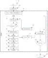
图1无人机视觉自主着陆仿真验证系统结构图;Fig. 1 Structural diagram of the UAV visual autonomous landing simulation verification system;
图2模块间数据交换关系图;Figure 2 is a diagram of the data exchange relationship between modules;
图3角点排序结果图;Fig. 3 Corner point sorting result graph;
图4系统坐标系关系图;Figure 4 System coordinate system relationship diagram;
图5无人机视觉自主着陆的仿真程序流程图;Fig. 5 flow chart of simulation program for UAV visual autonomous landing;
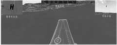
图6视觉仿真效果图;Figure 6 visual simulation effect diagram;
图7位置值对比图,其中蓝色曲线为真实值,红色曲线为估计值;Figure 7. Comparison of position values, where the blue curve is the real value and the red curve is the estimated value;
图8姿态值对比图,其中蓝色曲线为真实值,红色曲线为估计值;Figure 8 is a comparison chart of attitude values, where the blue curve is the real value and the red curve is the estimated value;
图中:1、VegaPrime模块,2、着陆地标检测模块,3、无人机位姿估计模块,4、无人机模块,5、着陆地标模块,6、摄像机模块,7、显示模块,8、角点检测,9、角点排序,10、姿态估计,11、位置估计,12、初始化模块。In the figure: 1. VegaPrime module, 2. Landing landmark detection module, 3. UAV pose estimation module, 4. UAV module, 5. Landing landmark module, 6. Camera module, 7. Display module, 8. Corner detection, 9. Corner sorting, 10. Pose estimation, 11. Position estimation, 12. Initialization module.
具体实施方式Detailed ways
无人机的整个着陆过程分为几个阶段,本发明假设无人机依靠GPS或其他导航设备引导其飞行至着陆地标上空,并且着陆地标总是在摄像机图像范围内。通过VegaPrime观察者模拟了机载摄像机功能,并利用VegaPrime能够设置无人机位姿的特点,通过无人机姿态估计算法的反解成功获取了模拟摄像机的内参矩阵。使用Creator三维建模工具设计了一个已知尺寸的H型着陆地标。在此基础上,使用VegaPrime和视觉算法结合,设计并实现了一种无人机视觉自主着陆仿真验证系统应用。The entire landing process of the UAV is divided into several stages. The present invention assumes that the UAV relies on GPS or other navigation equipment to guide it to fly over the landing mark, and the landing mark is always within the range of the camera image. The function of the airborne camera is simulated by the VegaPrime observer, and the characteristics of the UAV pose can be set by VegaPrime, and the internal parameter matrix of the simulated camera is successfully obtained through the inverse solution of the UAV pose estimation algorithm. An H-shaped landing landmark with known dimensions was designed using the Creator 3D modeling tool. On this basis, using the combination of VegaPrime and vision algorithm, a UAV visual autonomous landing simulation verification system application is designed and implemented.
如图1所示,一种无人机视觉自主着陆仿真验证系统,其特征是:至少包括VegaPrime模块1、着陆地标检测模块2、无人机位姿估计模块3,VegaPrime模块1用于展示无人机着陆的视景,着陆地标检测模块2用于对当前帧图像中进行图像处理,使用DP多边形拟合算法对着陆地标进行多边形拟合并提取角点,对所得角点重新排序与着陆地标对应后将结果传至无人机位姿估计模块3;无人机位姿估计模块3用于利用Courtney的方法得到无人机相对于着陆地标的旋转矩阵和平移矩阵,并通过旋转矩阵与欧拉角的关系得到无人机的三个姿态角,实时估计无人机位姿。As shown in Figure 1, a UAV visual autonomous landing simulation verification system is characterized by: at least including
所述VegaPrime模块1,至少包括无人机模块4、着陆地标模块5、摄像机模块6、显示模块7,无人机模块4中使用了Vegaprime模型库中的阿帕奇直升机,并在直升机中加入了前视摄像机和着陆用摄像机;着陆地标模块5中使用Creator建模工具建立了一个长5米,宽3米的H型地标;正视地标时,左上角角点定为地标坐标系原点,坐标为(0,0),其余各点顺时针排序,坐标依次为(1,0)、(1,2)、(2,2)、(2,0)、(3,0)、(3,5)、(2,5)(2,3)、(1,3)、(1,5)、(0,5);摄像机模块6为着陆用摄像机,其位置固定于无人机中心,垂直向下拍摄,根据一般机载摄像头视场角范围设置该观察者的水平FOV为30度,垂直FOV为20度,拍摄视频大小为360*240像素;通过无人机姿态估计算法反解求得模拟摄像机的内参矩阵,通过配置,将无人机位置调整到着陆地标原点正上方,且3个姿态角均为零,此时无人机相对于着陆地标的旋转矩阵R为单位阵,平移矩阵t=(0 0 h)T;在不同高度h下截取摄像头所拍摄到的地标图像,并通过图像处理得到图像中的12个角点像素坐标,分别将12个角点的物理坐标和像素坐标以及旋转矩阵、平移矩阵带入公式:The
解此方程组便可求得摄像机内参矩阵A,其中
如图3所示,所述着陆地标检测模块2,至少包括角点检测8、角点排序9,角点检测8首先对显示模块的摄像机图像进行灰度化处理,利用阈值分割的方法分离出地标区域,然后经过轮廓提取,并保留单连通闭合且长度为图像周长的0.5倍到1.5倍的轮廓得到地标的轮廓,对该轮廓进行DP多边形拟合后提取角点,保留角点像素坐标;角点排序9用于对角点检测8所得到的角点进行排序,角点检测8所保留的角点顺序为像素坐标系下v坐标最小的点为初始点,其余各点顺时针依次排列;当角点检测8所得图像角点a、b两点之间距离小于a、l两点之间距离时角点检测8所得排序即为正确顺序,当角点检测8所得图像角点a、b两点之间距离大于a、l两点之间距离时需要对所有点重新排序,遍历轮廓,取图像像素坐标系下u坐标最小的点为初始点,其余各点按顺时针依次排序。角点排序9所得图像角点最终排序结果和物理坐标系下地标各角点一一对应。As shown in Figure 3, the landing
如图4所示,所述无人机位姿估计模块3,至少包括姿态估计10、位置估计11,姿态估计10利用Courtney的方法,已知提前求得的摄像机内参矩阵A、地标12个角点物理坐标(xi,yi)和图像像素坐标(ui,vi),并带入公式:As shown in Figure 4, the UAV pose
得到一个超定方程组,通过SVD奇异值分解法解此超定方程组得到摄像机坐标系相对于着陆地标坐标系的旋转矩阵R和平移矩阵t,然后由欧拉角与旋转矩阵的关系可得:Obtain an overdetermined equation group, solve this overdetermined equation group by SVD singular value decomposition method to obtain the rotation matrix R and translation matrix t of the camera coordinate system relative to the landing landmark coordinate system, and then the relationship between the Euler angle and the rotation matrix can be obtained :
式中,无人机的俯仰角θ、滚转角φ、偏航角ψ分别为θ=arcsinr31,φ=arctan(-r32/r33),ψ=arctan(-r21/r11);位置估计11用于计算无人机所处位置,已知着陆地标的原点在VegaPrime坐标系中的坐标为(x,y,z)和姿态估计10所求得的平移向量(tx,ty,tz),由坐标系转关关系知无人机位置为(x-tx,y+ty,z+tz);OvXvYvZv为VegaPrime坐标系,OuXuYuZu为无人机坐标系,OcXcYcZc为摄像机坐标系,OwXwYwZw为着陆地标坐标系,uv为图像像素坐标系,其中VegaPrime坐标系与着陆地标坐标系X轴平行同向,Y、Z轴平行反向,摄像机坐标系与无人机坐标系原点始终重合且任何时间不存在旋转和平移;在无人机姿态角为0时,摄像机坐标系与着陆地标坐标系三轴平行同向,定义摄像机坐标系X轴绕着陆地标坐标系X轴转过的角度θ为俯仰角且逆时针为正,摄像机坐标系Y轴绕着陆地标坐标系Y轴转过的角度φ为滚转角且逆时针为正,摄像机坐标系Z轴绕着陆地标坐标系Z轴转过的角度ψ为偏航角且逆时针为正。In the formula, the pitch angle θ, roll angle φ, and yaw angle ψ of the UAV are respectively θ=arcsinr31 , φ=arctan(-r32 /r33 ), ψ=arctan(-r21 /r11 );
如图2所示,一种无人机视觉自主着陆仿真验证系统还包括初始化模块12,初始化模块12对摄像机模块6和无人机模块4进行模块配置数据初始化,将摄像机模块内参矩阵与着陆地标角点物理坐标传送至姿态估计10;摄像机模块6拍摄地标图像并发送图像数据到角点检测8,同时通过多窗口显示将摄像机模块6所拍摄到画面呈现在屏幕上;角点检测8对摄像机模块4传送的图像数据进行图像处理提取着陆地标角点像素坐标将结果交由角点排序9;角点排序9对所得到着陆地标角点进行排序,与物理坐标系下着陆地标各角点一一对应并将角点序列传送至姿态估计10;姿态估计10使用摄像机内参矩阵、着陆地标角点物理坐标和着陆地标角点像素坐标计算摄像机坐标系相对于着陆地标坐标系的旋转矩阵R和平移矩阵t,并利用欧拉角与旋转矩阵关系得到无人机姿态估计值;位置估计11使用姿态估计10所计算得到的平移矩阵和系统坐标系转换关系计算得到无人机位置估计值;最后显示模块7对由无人机模块4传送的位姿真实值和由姿态估计10、位置估计11传送的位姿估计值进行对比显示。As shown in Figure 2, a kind of unmanned aerial vehicle vision autonomous landing simulation verification system also includes initialization module 12, initialization module 12 carries out module configuration data initialization to camera module 6 and UAV module 4, and camera module intrinsic parameter matrix and landing landmark The physical coordinates of the corners are sent to the attitude estimation 10; the camera module 6 captures landmark images and sends the image data to the corner detection 8, and at the same time presents the pictures captured by the camera module 6 on the screen through a multi-window display; the corner detection 8 pairs of cameras The image data transmitted by module 4 is processed to extract the pixel coordinates of the corner points of the landing landmarks, and the result is passed to the corner point sorting 9; One-to-one correspondence and transfer the corner point sequence to attitude estimation 10; attitude estimation 10 calculates the rotation matrix R and translation of the camera coordinate system relative to the landing landmark coordinate system by using the camera internal reference matrix, the landing landmark corner point physical coordinates and the landing landmark corner point pixel coordinates matrix t, and use the relationship between the Euler angle and the rotation matrix to obtain the estimated value of the UAV's attitude; the position estimation 11 uses the translation matrix calculated by the attitude estimation 10 and the transformation relationship of the system coordinate system to calculate the estimated value of the UAV's position; finally displays Module 7 compares and displays the real pose value transmitted by UAV module 4 and the estimated pose value transmitted by pose estimation 10 and position estimation 11 .
如图5所示,一种无人机视觉自主着陆仿真验证方法,至少包括如下步骤:As shown in Figure 5, a simulation verification method for visual autonomous landing of UAVs at least includes the following steps:
步骤501:开始无人机自主着陆视觉导航仿真验证过程;Step 501: start the simulation verification process of the drone's autonomous landing visual navigation;
步骤502:载入acf配置文件,包括地形、无人机模型、着陆地标模型;Step 502: Load the acf configuration file, including terrain, UAV model, and landing landmark model;
步骤503:初始化VegaPrime各模块,初始化摄像机模块内参矩阵,载入着陆地标角点物理坐标,地形场景渲染;Step 503: Initialize each module of VegaPrime, initialize the internal reference matrix of the camera module, load the physical coordinates of the corner points of the landing landmarks, and render the terrain scene;
步骤504:基于系统时间控制无人机飞行,并提取无人机位姿值传至步骤513;Step 504: Control the flight of the drone based on the system time, and extract the pose value of the drone and send it to step 513;
步骤505:通过系统时间判断无人机是否到达着陆地标上空,若是则执行步骤506,否则执行步骤504,继续控制飞行;Step 505: judge whether the UAV has reached the sky above the landing mark by the system time, if so, execute
步骤506:获取摄像机拍摄的实时图像数据;Step 506: Obtain the real-time image data captured by the camera;
步骤507:通过阈值分割,轮廓提取,并保留单连通闭合且长度为图像周长的0.5倍到1.5倍的轮廓得到地标的轮廓;Step 507: Obtain the outline of the landmark by thresholding, extracting the outline, and retaining a single-connected closed outline whose length is 0.5 to 1.5 times the perimeter of the image;
步骤508:对步骤507获得的地标轮廓使用DP算法进行多边形拟合;Step 508: use the DP algorithm to perform polygon fitting on the landmark outline obtained in
步骤509:对步骤508的拟合结果提取角点,结果为像素坐标系下y坐标最小的点为初始点,其余各点依轮廓顺时针排列,并保留每个角点的像素坐标;Step 509: extract corner points from the fitting result of
步骤510:判断步骤508得到的角点排列方式,当a、b两点之间距离小于a、l两点之间距离时步骤509所得排序即为正确顺序,当a、b两点之间距离大于a、l两点之间距离时需要对所有点重新排序,遍历轮廓,取x坐标最小的点为初始点,其余各点按轮廓顺时针依次排序;Step 510: Judging the arrangement of corner points obtained in
步骤511:使用步骤510得到的角点像素坐标、初始化得到的角点物理坐标和摄像机内参矩阵求解无人机位姿估计值;Step 511: use the corner point pixel coordinates obtained in
步骤512:将步骤511得到的无人机位姿估计值输出至显示模块;Step 512: output the UAV pose estimation value obtained in step 511 to the display module;
步骤513:将步骤504获取的无人机位姿真实值传输至显示模块;Step 513: Transmit the real value of the UAV pose obtained in
步骤514:结合步骤512与513所得数据,将无人机位姿真实值和估计值以列表的形式对比显示;Step 514: Combining the data obtained in
步骤515:判断着陆阶段是否完成,如果是,则无人机自主着陆视觉导航仿真验证过程结束,否则转至步骤504;Step 515: Determine whether the landing phase is completed, if yes, the UAV autonomous landing visual navigation simulation verification process ends, otherwise go to step 504;
步骤516:无人机自主着陆视觉导航仿真验证过程结束。Step 516: The simulation verification process of the drone's autonomous landing visual navigation is over.
其中虚线框内为VegaPrime程序的帧循环,程序正常执行后将始终在虚线框内执行,其余步骤只执行一次。Among them, the frame loop of the VegaPrime program is inside the dotted line box. After the program is executed normally, it will always be executed in the dotted line box, and the rest of the steps will only be executed once.
视觉仿真效果如图6所示,该仿真系统可以实时显示机载摄像机所拍摄的图像,展示无人机整个着陆过程,并且能将无人机真实位姿值和估计值对比实时输出,这样我们就可以直观的测试和分析视觉导航算法的可行性。The visual simulation effect is shown in Figure 6. The simulation system can display the images captured by the airborne camera in real time, show the entire landing process of the UAV, and can compare the real pose value of the UAV with the estimated value and output it in real time. In this way, we You can intuitively test and analyze the feasibility of the visual navigation algorithm.
位姿估计仿真结果如图7、图8所示,对比位姿真实值与估计值曲线可知,估计值基本符合真实情况,在高度为40米时无人机已基本调整好着陆姿态,且位置误差不超过1米,姿态误差在2度以内,仿真结果证明了该系统的有效性和正确性。The simulation results of pose estimation are shown in Figure 7 and Figure 8. Comparing the curves of the real value and the estimated value of the pose, it can be seen that the estimated value is basically in line with the real situation. When the height is 40 meters, the UAV has basically adjusted the landing attitude, and the position The error is not more than 1 meter, and the attitude error is within 2 degrees. The simulation results prove the effectiveness and correctness of the system.
本实施例没有详细叙述的部件和结构属本行业的公知部件和常用结构或常用手段,这里不一一叙述。The components and structures not described in detail in this embodiment are known components and common structures or common means in this industry, and are not described here one by one.
Claims (6)
Translated fromChinesePriority Applications (1)
| Application Number | Priority Date | Filing Date | Title |
|---|---|---|---|
| CN201310350048.0ACN103424126B (en) | 2013-08-12 | 2013-08-12 | A kind of unmanned plane vision independent landing simulation checking system and method |
Applications Claiming Priority (1)
| Application Number | Priority Date | Filing Date | Title |
|---|---|---|---|
| CN201310350048.0ACN103424126B (en) | 2013-08-12 | 2013-08-12 | A kind of unmanned plane vision independent landing simulation checking system and method |
Publications (2)
| Publication Number | Publication Date |
|---|---|
| CN103424126Atrue CN103424126A (en) | 2013-12-04 |
| CN103424126B CN103424126B (en) | 2016-02-24 |
Family
ID=49649227
Family Applications (1)
| Application Number | Title | Priority Date | Filing Date |
|---|---|---|---|
| CN201310350048.0AExpired - Fee RelatedCN103424126B (en) | 2013-08-12 | 2013-08-12 | A kind of unmanned plane vision independent landing simulation checking system and method |
Country Status (1)
| Country | Link |
|---|---|
| CN (1) | CN103424126B (en) |
Cited By (25)
| Publication number | Priority date | Publication date | Assignee | Title |
|---|---|---|---|---|
| CN104503459A (en)* | 2014-11-25 | 2015-04-08 | 深圳市鸣鑫航空科技有限公司 | Multi-rotor unmanned aerial vehicle recycling system |
| CN105929837A (en)* | 2016-04-23 | 2016-09-07 | 上海大学 | Small unmanned rotorcraft autonomous landing attitude estimation method |
| CN105959625A (en)* | 2016-05-04 | 2016-09-21 | 北京博瑞爱飞科技发展有限公司 | Method and device of controlling unmanned plane tracking shooting |
| CN104197928B (en)* | 2014-08-29 | 2017-01-18 | 西北工业大学 | Multi-camera collaboration-based method for detecting, positioning and tracking unmanned aerial vehicle |
| CN106462822A (en)* | 2014-05-02 | 2017-02-22 | 谷歌公司 | Machine-readable delivery platform for automated package delivery |
| CN106500699A (en)* | 2016-05-25 | 2017-03-15 | 上海铸天智能科技有限公司 | A kind of position and orientation estimation method suitable for Autonomous landing in unmanned plane room |
| CN107077113A (en)* | 2014-10-27 | 2017-08-18 | 深圳市大疆创新科技有限公司 | UAV flight display |
| US9824324B2 (en) | 2014-05-13 | 2017-11-21 | Google Llc | Automated package relocation from an unmanned kiosk |
| US9911341B2 (en) | 2014-10-22 | 2018-03-06 | Google Llc | Automated package delivery to a delivery receptacle |
| CN108873917A (en)* | 2018-07-05 | 2018-11-23 | 太原理工大学 | A kind of unmanned plane independent landing control system and method towards mobile platform |
| CN109240327A (en)* | 2018-09-11 | 2019-01-18 | 陕西千山航空电子有限责任公司 | A kind of fixed wing aircraft mission phase recognition methods |
| CN109460046A (en)* | 2018-10-17 | 2019-03-12 | 吉林大学 | A kind of unmanned plane identify naturally not with independent landing method |
| CN109598758A (en)* | 2018-11-21 | 2019-04-09 | 三峡大学 | It is a kind of can vision positioning unmanned plane landing platform and unmanned plane drop point modification method |
| CN109613923A (en)* | 2018-11-06 | 2019-04-12 | 武汉华中天经通视科技有限公司 | A kind of unmanned helicopter warship control method |
| CN109612333A (en)* | 2018-11-08 | 2019-04-12 | 北京航天自动控制研究所 | A vision-aided guidance system for vertical recovery of reusable rockets |
| CN110058604A (en)* | 2019-05-24 | 2019-07-26 | 中国科学院地理科学与资源研究所 | A kind of accurate landing system of unmanned plane based on computer vision |
| CN110083177A (en)* | 2019-05-06 | 2019-08-02 | 湖北汽车工业学院 | A kind of quadrotor and control method of view-based access control model landing |
| CN111367194A (en)* | 2018-12-25 | 2020-07-03 | 北京欣奕华科技有限公司 | Visual algorithm verification method and device |
| US10748106B2 (en) | 2014-10-22 | 2020-08-18 | Google Llc | Mobile delivery receptacle |
| CN111982291A (en)* | 2019-05-23 | 2020-11-24 | 杭州海康机器人技术有限公司 | Fire point positioning method, device and system based on unmanned aerial vehicle |
| CN112219195A (en)* | 2019-08-30 | 2021-01-12 | 深圳市大疆创新科技有限公司 | Application program testing method, device and storage medium |
| CN112764355A (en)* | 2020-12-05 | 2021-05-07 | 西安翔腾微电子科技有限公司 | Vision-based aircraft autonomous landing positioning development system and method |
| US11217112B2 (en) | 2014-09-30 | 2022-01-04 | SZ DJI Technology Co., Ltd. | System and method for supporting simulated movement |
| CN114689030A (en)* | 2022-06-01 | 2022-07-01 | 中国兵器装备集团自动化研究所有限公司 | Unmanned aerial vehicle auxiliary positioning method and system based on airborne vision |
| US11440657B2 (en) | 2018-01-29 | 2022-09-13 | Ge Aviation Systems Limited | Aerial vehicles with machine vision |
Citations (2)
| Publication number | Priority date | Publication date | Assignee | Title |
|---|---|---|---|---|
| KR20070099093A (en)* | 2006-04-03 | 2007-10-09 | 동서대학교산학협력단 | Development method of multi-input device compatible wrapper class for interactive content production |
| CN102800130A (en)* | 2012-07-04 | 2012-11-28 | 哈尔滨工程大学 | Water level-close aircraft maneuvering flight visual scene simulation method |
- 2013
- 2013-08-12CNCN201310350048.0Apatent/CN103424126B/ennot_activeExpired - Fee Related
Patent Citations (2)
| Publication number | Priority date | Publication date | Assignee | Title |
|---|---|---|---|---|
| KR20070099093A (en)* | 2006-04-03 | 2007-10-09 | 동서대학교산학협력단 | Development method of multi-input device compatible wrapper class for interactive content production |
| CN102800130A (en)* | 2012-07-04 | 2012-11-28 | 哈尔滨工程大学 | Water level-close aircraft maneuvering flight visual scene simulation method |
Non-Patent Citations (3)
| Title |
|---|
| ZHIJIA SUI等: "Design and Realization of Vision-Based Landing Simulation Verification System for UH Based on Vega Prime/MFC", 《NATIONAL NATURAL SCIENCE FOUNDATION OF CHINA》* |
| 孙伟光,郝应光: "基于地标几何特征的无人直升机自主降落", 《计算机应用》* |
| 李华伟等: "基于Creator/Vega Prime的无人机着舰仿真验证系统设计", 《中国电子科学研究院学报》* |
Cited By (40)
| Publication number | Priority date | Publication date | Assignee | Title |
|---|---|---|---|---|
| US10242334B2 (en) | 2014-05-02 | 2019-03-26 | Google Llc | Machine-readable delivery platform for automated package delivery |
| CN106462822B (en)* | 2014-05-02 | 2019-07-26 | 谷歌有限责任公司 | Machine-readable delivery platform for automated package delivery |
| US10650342B2 (en) | 2014-05-02 | 2020-05-12 | Google Llc | Machine-readable delivery platform for automated package delivery |
| CN106462822A (en)* | 2014-05-02 | 2017-02-22 | 谷歌公司 | Machine-readable delivery platform for automated package delivery |
| US9864967B2 (en) | 2014-05-02 | 2018-01-09 | Google Llc | Machine-readable delivery platform for automated package delivery |
| US10915852B2 (en) | 2014-05-13 | 2021-02-09 | Google Llc | Automated package relocation from an unmanned kiosk |
| US9824324B2 (en) | 2014-05-13 | 2017-11-21 | Google Llc | Automated package relocation from an unmanned kiosk |
| CN104197928B (en)* | 2014-08-29 | 2017-01-18 | 西北工业大学 | Multi-camera collaboration-based method for detecting, positioning and tracking unmanned aerial vehicle |
| US11217112B2 (en) | 2014-09-30 | 2022-01-04 | SZ DJI Technology Co., Ltd. | System and method for supporting simulated movement |
| US9911341B2 (en) | 2014-10-22 | 2018-03-06 | Google Llc | Automated package delivery to a delivery receptacle |
| US10403156B2 (en) | 2014-10-22 | 2019-09-03 | Google Llc | Automated package delivery to a delivery receptacle |
| US10748106B2 (en) | 2014-10-22 | 2020-08-18 | Google Llc | Mobile delivery receptacle |
| CN107077113A (en)* | 2014-10-27 | 2017-08-18 | 深圳市大疆创新科技有限公司 | UAV flight display |
| CN104503459A (en)* | 2014-11-25 | 2015-04-08 | 深圳市鸣鑫航空科技有限公司 | Multi-rotor unmanned aerial vehicle recycling system |
| CN105929837B (en)* | 2016-04-23 | 2019-04-02 | 上海大学 | Miniature self-service gyroplane independent landing position and orientation estimation method |
| CN105929837A (en)* | 2016-04-23 | 2016-09-07 | 上海大学 | Small unmanned rotorcraft autonomous landing attitude estimation method |
| CN105959625A (en)* | 2016-05-04 | 2016-09-21 | 北京博瑞爱飞科技发展有限公司 | Method and device of controlling unmanned plane tracking shooting |
| CN106500699A (en)* | 2016-05-25 | 2017-03-15 | 上海铸天智能科技有限公司 | A kind of position and orientation estimation method suitable for Autonomous landing in unmanned plane room |
| CN106500699B (en)* | 2016-05-25 | 2019-06-18 | 上海铸天智能科技有限公司 | A kind of position and orientation estimation method suitable for Autonomous landing in unmanned plane room |
| US11440657B2 (en) | 2018-01-29 | 2022-09-13 | Ge Aviation Systems Limited | Aerial vehicles with machine vision |
| US12205476B2 (en) | 2018-01-29 | 2025-01-21 | Ge Aviation Systems Limited | Aerial vehicles with machine vision |
| CN108873917A (en)* | 2018-07-05 | 2018-11-23 | 太原理工大学 | A kind of unmanned plane independent landing control system and method towards mobile platform |
| CN109240327A (en)* | 2018-09-11 | 2019-01-18 | 陕西千山航空电子有限责任公司 | A kind of fixed wing aircraft mission phase recognition methods |
| CN109240327B (en)* | 2018-09-11 | 2021-10-12 | 陕西千山航空电子有限责任公司 | Method for identifying flight phase of fixed-wing aircraft |
| CN109460046B (en)* | 2018-10-17 | 2021-08-06 | 吉林大学 | A method for unmanned aerial vehicle natural landmark recognition and autonomous landing |
| CN109460046A (en)* | 2018-10-17 | 2019-03-12 | 吉林大学 | A kind of unmanned plane identify naturally not with independent landing method |
| CN109613923A (en)* | 2018-11-06 | 2019-04-12 | 武汉华中天经通视科技有限公司 | A kind of unmanned helicopter warship control method |
| CN109612333A (en)* | 2018-11-08 | 2019-04-12 | 北京航天自动控制研究所 | A vision-aided guidance system for vertical recovery of reusable rockets |
| CN109612333B (en)* | 2018-11-08 | 2021-07-09 | 北京航天自动控制研究所 | A vision-aided guidance system for vertical recovery of reusable rockets |
| CN109598758A (en)* | 2018-11-21 | 2019-04-09 | 三峡大学 | It is a kind of can vision positioning unmanned plane landing platform and unmanned plane drop point modification method |
| CN111367194A (en)* | 2018-12-25 | 2020-07-03 | 北京欣奕华科技有限公司 | Visual algorithm verification method and device |
| CN110083177A (en)* | 2019-05-06 | 2019-08-02 | 湖北汽车工业学院 | A kind of quadrotor and control method of view-based access control model landing |
| CN111982291A (en)* | 2019-05-23 | 2020-11-24 | 杭州海康机器人技术有限公司 | Fire point positioning method, device and system based on unmanned aerial vehicle |
| CN111982291B (en)* | 2019-05-23 | 2022-11-04 | 杭州海康机器人技术有限公司 | Fire point positioning method, device and system based on unmanned aerial vehicle |
| CN110058604A (en)* | 2019-05-24 | 2019-07-26 | 中国科学院地理科学与资源研究所 | A kind of accurate landing system of unmanned plane based on computer vision |
| WO2021035702A1 (en)* | 2019-08-30 | 2021-03-04 | 深圳市大疆创新科技有限公司 | Application program testing method, device and storage medium |
| CN112219195A (en)* | 2019-08-30 | 2021-01-12 | 深圳市大疆创新科技有限公司 | Application program testing method, device and storage medium |
| CN112764355A (en)* | 2020-12-05 | 2021-05-07 | 西安翔腾微电子科技有限公司 | Vision-based aircraft autonomous landing positioning development system and method |
| CN112764355B (en)* | 2020-12-05 | 2022-12-13 | 西安翔腾微电子科技有限公司 | Vision-based autonomous landing positioning development system and method for airplane |
| CN114689030A (en)* | 2022-06-01 | 2022-07-01 | 中国兵器装备集团自动化研究所有限公司 | Unmanned aerial vehicle auxiliary positioning method and system based on airborne vision |
Also Published As
| Publication number | Publication date |
|---|---|
| CN103424126B (en) | 2016-02-24 |
Similar Documents
| Publication | Publication Date | Title |
|---|---|---|
| CN103424126B (en) | A kind of unmanned plane vision independent landing simulation checking system and method | |
| Yang et al. | An onboard monocular vision system for autonomous takeoff, hovering and landing of a micro aerial vehicle | |
| CN107202982B (en) | A kind of beacon arrangement and image processing method based on UAV position and orientation calculating | |
| US20210405654A1 (en) | Autonomous taking off, positioning and landing of unmanned aerial vehicles (uav) on a mobile platform | |
| US8942964B2 (en) | Optical state estimation and simulation environment for unmanned aerial vehicles | |
| Gans et al. | A hardware in the loop simulation platform for vision-based control of unmanned air vehicles | |
| CN114488848B (en) | Unmanned aerial vehicle autonomous flight system and simulation experiment platform for indoor building space | |
| CN107194399B (en) | A method, system and unmanned aerial vehicle for visual calibration | |
| US20200012756A1 (en) | Vision simulation system for simulating operations of a movable platform | |
| CN109839945B (en) | UAV landing method, UAV landing device and computer readable storage medium | |
| CN112925223A (en) | Unmanned aerial vehicle three-dimensional tracking virtual test simulation system based on visual sensing network | |
| CN113313824B (en) | A method for constructing three-dimensional semantic maps | |
| US20180233061A1 (en) | Unmanned vehicle simulator | |
| CN115291536B (en) | Verification method of semi-physical simulation platform for UAV tracking ground targets based on vision | |
| CN106780337B (en) | Unmanned aerial vehicle carrier landing visual simulation method based on two-dimensional image | |
| Fan et al. | Vision algorithms for fixed-wing unmanned aerial vehicle landing system | |
| CN117115252B (en) | A vision-based spatial pose estimation method for bionic flapping-wing UAVs | |
| Sobel et al. | Camera calibration for tracked vehicles augmented reality applications | |
| Wang et al. | Monocular vision and IMU based navigation for a small unmanned helicopter | |
| Cheon et al. | Hardware-in-the-loop simulation platform for image-based object tracking method using small UAV | |
| Parsons et al. | Real-time automated aerial refueling using stereo vision | |
| Rüter et al. | Using only synthetic images to train a drogue detector for aerial refueling | |
| Piponidis et al. | Towards a fully autonomous uav controller for moving platform detection and landing | |
| Dubey et al. | Droan-disparity-space representation for obstacle avoidance: Enabling wire mapping & avoidance | |
| Li-Chee-Ming et al. | Determination of UAS trajectory in a known environment from FPV video |
Legal Events
| Date | Code | Title | Description |
|---|---|---|---|
| C06 | Publication | ||
| PB01 | Publication | ||
| C10 | Entry into substantive examination | ||
| SE01 | Entry into force of request for substantive examination | ||
| C14 | Grant of patent or utility model | ||
| GR01 | Patent grant | ||
| CF01 | Termination of patent right due to non-payment of annual fee | Granted publication date:20160224 Termination date:20160812 | |
| CF01 | Termination of patent right due to non-payment of annual fee |