CN103410944A - Integrated transaxle - Google Patents
Integrated transaxleDownload PDFInfo
- Publication number
- CN103410944A CN103410944ACN2013103835643ACN201310383564ACN103410944ACN 103410944 ACN103410944 ACN 103410944ACN 2013103835643 ACN2013103835643 ACN 2013103835643ACN 201310383564 ACN201310383564 ACN 201310383564ACN 103410944 ACN103410944 ACN 103410944A
- Authority
- CN
- China
- Prior art keywords
- gear
- power
- planetary
- speed
- push rod
- Prior art date
- Legal status (The legal status is an assumption and is not a legal conclusion. Google has not performed a legal analysis and makes no representation as to the accuracy of the status listed.)
- Granted
Links
- 230000007246mechanismEffects0.000claimsabstractdescription64
- 230000008859changeEffects0.000claimsabstractdescription15
- 229910000831SteelInorganic materials0.000claimsdescription8
- 239000010959steelSubstances0.000claimsdescription8
- 238000005096rolling processMethods0.000claimsdescription6
- 238000010276constructionMethods0.000claims5
- 230000000295complement effectEffects0.000claims1
- 238000003754machiningMethods0.000claims1
- 230000005540biological transmissionEffects0.000abstractdescription50
- 239000003638chemical reducing agentSubstances0.000abstractdescription2
- 230000035945sensitivityEffects0.000abstract1
- 230000009467reductionEffects0.000description8
- 238000010586diagramMethods0.000description5
- 241000209094OryzaSpecies0.000description4
- 235000007164Oryza sativaNutrition0.000description4
- 238000009434installationMethods0.000description4
- 235000009566riceNutrition0.000description4
- 230000009977dual effectEffects0.000description3
- 230000033001locomotionEffects0.000description3
- 230000001105regulatory effectEffects0.000description3
- 240000002791Brassica napusSpecies0.000description2
- 235000004977Brassica sinapistrumNutrition0.000description2
- 238000000034methodMethods0.000description2
- 238000010899nucleationMethods0.000description2
- 235000013311vegetablesNutrition0.000description2
- 230000009471actionEffects0.000description1
- 230000009286beneficial effectEffects0.000description1
- 230000000694effectsEffects0.000description1
- 238000004519manufacturing processMethods0.000description1
- 230000007935neutral effectEffects0.000description1
- 230000003068static effectEffects0.000description1
Images


Landscapes
- Retarders (AREA)
Abstract
Translated fromChinese
Description
Translated fromChinese技术领域technical field
本发明涉及农用机械设备中的驱动系统领域,尤其涉及一种集成无级变速装置、差速器以及三速动力输出装置的集成式变速驱动桥。The invention relates to the field of drive systems in agricultural machinery, in particular to an integrated variable speed drive axle integrating a continuously variable transmission device, a differential device and a three-speed power output device.
背景技术Background technique
目前,水稻插秧机、水稻直播机、蔬菜移栽机、油菜移栽机等田间作业机具通常都是采用驾驶式或人力手扶自走式。其中,驾驶式机具虽然可以大幅减少劳动强度,但是由于此类机具通常单机质量比较低,如果加载驾驶员,会使得整机总质量大幅增加,且由于增加驾驶员后,机具的驱动力,行走系统等都要做相应的改进,使得整机成本上升,适用性降低。而人力手扶自走式可以解决上述问题,但由于在作业过程中,驾驶员始终要跟着机械走,劳动强度大,效率低。At present, field operation tools such as rice transplanters, rice direct seeding machines, vegetable transplanters, and rapeseed transplanters usually use driving or manual self-propelled. Among them, although driving-type implements can greatly reduce labor intensity, because such implements usually have a relatively low stand-alone mass, if the driver is loaded, the total mass of the entire machine will increase significantly, and due to the addition of drivers, the driving force of the implements, walking The system, etc. must be improved accordingly, which will increase the cost of the whole machine and reduce the applicability. The manpower hand-held self-propelled type can solve the above problems, but since the driver always follows the machine during the operation, the labor intensity is high and the efficiency is low.
基于上述原因,如果能采用遥控驾驶的方式就能解决上述问题。而在设备的实际应用中,无论采用驾驶式或人力手扶自走式机具,通常都包含有发动机、离合器、变速器以及牙嵌式转向离合器。要实现遥控驾驶,在发动机油门电子控制大小、离合器电子控制离合都比较容易实现,但是变速器换挡、机具转向很难实现电子控制,若采用传统的方法,也会使得机具结构十分复杂,同时,还会因为操作难度增大、成本大幅上升,而失去其生产和使用的意义。Based on the above reasons, if the mode of remote control driving can be adopted, the above problems can be solved. In the actual application of the equipment, no matter whether it is a driving type or a manpower hand-held self-propelled implement, it usually includes an engine, a clutch, a transmission, and a jaw type steering clutch. In order to realize remote control driving, it is relatively easy to realize the electronic control of the throttle of the engine and the electronic control of the clutch, but it is difficult to realize electronic control of the transmission shifting and the steering of the machine. If the traditional method is used, the structure of the machine will be very complicated. At the same time, It will also lose the meaning of its production and use because of the increased difficulty of operation and the sharp increase in cost.
发明内容Contents of the invention
本发明所解决的技术问题在于提供一种集成式变速驱动桥,以解决上述背景技术中的缺点。The technical problem solved by the present invention is to provide an integrated transaxle to solve the above-mentioned shortcomings in the background technology.
本发明所解决的技术问题采用以下技术方案来实现:The technical problem solved by the present invention adopts following technical scheme to realize:
一种集成式变速驱动桥,其主体为一封闭箱体,箱体内依次封装有外接设备动力供给机构、动力输入及外接设备动力变速机构、无级变速及差速控制机构以及车轮传动装置这四个部分。An integrated transaxle, the main body of which is a closed box, which is packaged in turn with four components: the power supply mechanism for external equipment, the power input and power transmission mechanism for external equipment, the continuously variable speed and differential control mechanism, and the wheel transmission device. parts.
其中,外接设备动力供给机构安装在封闭箱体内一侧,其两侧通过端盖封闭,端盖内套装有限位轴承,并通过限位轴承固定输出动力轴,此输出动力轴上从左至右分别设计有三处外花键,分别用于箱内变速齿轮、双联齿轮以及箱外动力输出组件的安装和动力传递。Among them, the power supply mechanism of the external equipment is installed on one side of the closed box, and its two sides are closed by the end cover. The limit bearing is set in the end cover, and the output power shaft is fixed by the limit bearing. The output power shaft is from left to right. Three external splines are respectively designed, which are respectively used for the installation and power transmission of the transmission gear in the box, the double gear and the power output assembly outside the box.
动力输入及外接设备动力变速机构固定在设备动力供给机构以及无级变速及差速控制机构之间,包括两根独立的轴结构,所述下部轴杆为动力输入轴,其两端通过限位轴承固定在两侧的端盖上,而轴径上设置有滑动外花键,且在滑动外花键上依次套装有一个滑动齿轮、主动力齿轮以及一个滑动双联齿轮;所述上部轴杆为一端面带有多个限位凹槽的换挡推杆,此换挡推杆可在轴向上移动,且其带限位凹槽的一端卡接在一个推杆限位套内,通过限位凹槽可实现换挡推杆档位的限定;而两根轴杆之间的联动通过一个换挡拨叉实现,此换挡拨叉为一个三联叉结构,其下部连接滑动齿轮以及滑动双联齿轮上,上部则通过一个挡圈固定在换挡推杆上,使得滑动齿轮和滑动双联齿轮在换挡拨叉的拨动下可沿滑动外花键滑动,以变换滑动齿轮、滑动双联齿轮和设备动力供给机构中变速齿轮、双联齿轮的啮合方式。The power input and external equipment power transmission mechanism is fixed between the equipment power supply mechanism and the continuously variable speed and differential control mechanism, including two independent shaft structures. The lower shaft is the power input shaft, and its two ends pass through the limit The bearings are fixed on the end covers on both sides, and the shaft diameter is provided with sliding external splines, and a sliding gear, a main power gear and a sliding double gear are sequentially set on the sliding external splines; the upper shaft It is a shift push rod with multiple limit grooves on one end surface. The shift push rod can move in the axial direction, and its end with limit grooves is clamped in a push rod limit sleeve. The limit groove can realize the limitation of the shift position of the shift push rod; and the linkage between the two shafts is realized by a shift fork, which is a triple fork structure, the lower part of which is connected to the sliding gear and the sliding On the double gear, the upper part is fixed on the shift push rod through a retaining ring, so that the sliding gear and the sliding double gear can slide along the sliding outer spline under the toggle of the shift fork to change the sliding gear, sliding The meshing mode of the speed change gear and the dual gear in the dual gear and the power supply mechanism of the equipment.
无级变速及差速控制机构包括两个行星驱动轮结构,且这两个行星驱动轮结构对称安装在中间轴上;而所述中间轴两端通过轴承支撑,利用端盖封闭,中间轴上两组行星齿轮机构之间安装有一级减速从动齿轮,所述的一级减速从动齿轮一端用台阶定位,另一端用卡环定位,且所述一级减速从动齿轮与动力输入及外接设备动力变速机构中的主动力齿轮啮合,一级减速从动齿轮的通过中间的花键将动力传递给中间轴,中间轴再将动力传递给行星变速器机构。而安装在无级变速及差速控制机构中的每个行星齿轮结构中均包括有太阳轮、四个行星轮、由行星轮支架组成的行星架以及齿圈,所述太阳轮通过花键连接的方式或直接焊接在中间轴上,行星架通过支架两端支撑,所述的行星架中的行星轮通过销钉固接在支撑架上,所述行星架的侧端加工有外齿轮做下一级的动力输入齿轮,所述行星架外齿轮与车轮传动装置中半轴的驱动齿轮啮合,将行星齿轮机构的动力输出给驱动半轴,行星架通过两组滚针轴承支撑在中间轴上。The continuously variable speed and differential control mechanism includes two planetary drive wheel structures, and the two planetary drive wheel structures are symmetrically installed on the intermediate shaft; and the two ends of the intermediate shaft are supported by bearings and closed by end covers. A first-stage reduction driven gear is installed between the two sets of planetary gear mechanisms, one end of the first-stage reduction driven gear is positioned with a step, and the other end is positioned with a snap ring, and the first-stage reduction driven gear is connected to the power input and external connection The active power gear in the power transmission mechanism of the equipment meshes, and the first-stage reduction driven gear transmits the power to the intermediate shaft through the spline in the middle, and the intermediate shaft transmits the power to the planetary transmission mechanism. Each planetary gear structure installed in the continuously variable speed and differential control mechanism includes a sun gear, four planetary gears, a planetary carrier composed of planetary gear brackets, and a ring gear. The sun gears are connected by splines. or directly welded on the intermediate shaft, the planetary carrier is supported by both ends of the bracket, the planetary wheels in the planetary carrier are fixed on the support frame through pins, and the side ends of the planetary carrier are processed with external gears for the next step The power input gear of the first stage, the outer gear of the planet carrier meshes with the driving gear of the half shaft in the wheel transmission, and outputs the power of the planetary gear mechanism to the driving half shaft, and the planet carrier is supported on the intermediate shaft by two sets of needle bearings.
在上述行星齿轮结构中,太阳轮做动力输入轮,行星架做动力输出,齿圈做调速机构,所述的齿圈为内啮合齿圈,在齿圈的外圆加工有蜗轮,蜗轮与电机控制的蜗杆配合,组成一套运动副,所述的蜗轮与齿圈的组合结构,在电机的带动下,能控制齿圈旋转及旋转方向、停止,由于所述的行星齿轮结构组合的电机控制的蜗轮蜗杆结构,形成一种由太阳轮与蜗杆驱动的双动力驱动结构,根据行星齿轮机构的运动特征,在太阳轮固定转速而蜗杆变转速运动时,行星架输出速度可以无极可调。In the above-mentioned planetary gear structure, the sun gear is used as the power input wheel, the planetary carrier is used as the power output, and the ring gear is used as the speed regulating mechanism. The ring gear is an internal meshing ring gear. The worm controlled by the motor cooperates to form a set of motion pairs. The combined structure of the worm gear and the ring gear can control the rotation, rotation direction and stop of the ring gear under the drive of the motor. Because the motor combined with the planetary gear structure The controlled worm gear structure forms a dual power drive structure driven by the sun gear and the worm. According to the motion characteristics of the planetary gear mechanism, when the sun gear rotates at a fixed speed and the worm rotates at a variable speed, the output speed of the planet carrier can be infinitely adjustable.
由于行星齿轮机构对称的布置在中间轴上,如果控制两组行星齿轮机构的齿圈外端的蜗轮的转速相同,两行星架端输出可以无级变速的相同速度,如果控制两组行星齿轮机构的齿圈外端的蜗轮的转速不同,则行星架输出不同的速度,实现驱动轮差速。可见所述的行星齿轮机构及其调速装置能实现无级变速与差速。Since the planetary gear mechanism is symmetrically arranged on the intermediate shaft, if the worm gears at the outer ends of the ring gears of the two sets of planetary gear mechanisms are controlled at the same speed, the two planet carrier ends can output the same speed that can be continuously variable. If the two sets of planetary gear mechanisms are controlled The speed of the worm gear at the outer end of the ring gear is different, and the planet carrier outputs different speeds to realize the differential speed of the driving wheel. It can be seen that the planetary gear mechanism and its speed regulating device can realize stepless speed change and differential speed.
车轮传动装置位于无级变速及差速控制机构一侧,两侧通过端盖固定在主箱体上,其内部包括两根驱动半轴以及两个套装在驱动轴上的驱动齿轮,所述驱动齿轮与行星架结构中的外部输出啮合齿盘啮合。The wheel transmission device is located on one side of the continuously variable transmission and differential speed control mechanism, and the two sides are fixed on the main box body through the end cover. Its interior includes two driving half shafts and two driving gears set on the driving shaft. The gears mesh with the outer output meshing chainrings in the planet carrier structure.
在本发明的设备动力供给机构中,输出动力轴的最右端设置有外螺纹和防松销孔,用于固定外部安装的车轮组件。In the equipment power supply mechanism of the present invention, the rightmost end of the output power shaft is provided with an external thread and a locking pin hole for fixing the externally installed wheel assembly.
在本发明的动力输入及外接设备动力变速机构中,动力输入轴的端盖左侧伸出部分上开有防松销孔、外螺纹及外花键,用于外部动力组件的安装和动力传递。In the power transmission mechanism of the power input and external equipment of the present invention, the protruding part on the left side of the end cover of the power input shaft is provided with anti-loosening pin holes, external threads and external splines, which are used for the installation and power transmission of external power components. .
在本发明的动力输入及外接设备动力变速机构中,所述推杆限位套为一个带限位钢球以及内置弹簧的套筒结构,其限位钢球与限位凹槽的尺寸相匹配,且整个推杆限位套的位置与主箱体保持相对固定。In the power input and external device power transmission mechanism of the present invention, the push rod limit sleeve is a sleeve structure with a limit steel ball and a built-in spring, and the limit steel ball matches the size of the limit groove , and the position of the entire push rod limit sleeve remains relatively fixed with the main box.
在本发明中,所述安装在无级变速及差速控制机构中的每个行星驱动轮结构中的行星驱动轮与蜗轮之间还设置有一个滚动轴承用于限位支撑,并能有效地进行辅助传动。In the present invention, a rolling bearing is provided between the planetary drive wheel and the worm wheel in each planetary drive wheel structure installed in the continuously variable transmission and differential control mechanism for limit support, and can effectively carry out Auxiliary drive.
在本发明中,所述车轮传动装置的驱动半轴在伸出主箱体的端盖部分中通过双轴承套装的方式来增加驱动轴输出的稳定性,两半轴之间采用连接轴承支撑,既增加驱动半轴稳定性,也提高了传动的效率。In the present invention, the driving half-shaft of the wheel transmission is extended out of the end cover of the main box to increase the stability of the output of the driving shaft through double bearings, and the two half-shafts are supported by connecting bearings. It not only increases the stability of the driving half shaft, but also improves the efficiency of the transmission.
有益效果:本发明将变速器、主减速器、差速器和动力输出装置集成在一体,形成一个集成化的变速驱动桥,其中的蜗轮蜗杆结构在调速电机的控制下适时调整行星齿轮传动组件中的齿圈的转速,变速器可输出空挡、无级变速的前进挡和倒档,也可以实现左右驱动轮的限扭差速。可应用于水稻插秧机、水稻直播机、蔬菜移栽机、油菜移栽机等田间作业机具中,可有效提高其自动化水平,使得对这类机具的远端遥控操作成为可能。Beneficial effects: the present invention integrates the transmission, the final reducer, the differential and the power output device to form an integrated transaxle, in which the worm and gear structure adjusts the planetary gear transmission assembly in good time under the control of the speed regulating motor According to the speed of the ring gear in the transmission, the transmission can output neutral, continuously variable forward gear and reverse gear, and can also realize the torque-limited differential speed of the left and right driving wheels. It can be applied to field operation equipment such as rice transplanter, rice direct seeding machine, vegetable transplanter, rapeseed transplanter, etc., which can effectively improve its automation level and make remote remote control operation of such equipment possible.
附图说明Description of drawings
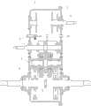
图1为本发明的较佳实施例的内部结构示意图。Fig. 1 is a schematic diagram of the internal structure of a preferred embodiment of the present invention.
图2为本发明的较佳实施例的侧面视图。Figure 2 is a side view of a preferred embodiment of the present invention.
图3为本发明的较佳实施例的外接设备动力供给机构示意图。Fig. 3 is a schematic diagram of a power supply mechanism of an external device according to a preferred embodiment of the present invention.
图4为本发明的较佳实施例的动力输入及外接设备动力变速机构示意图。Fig. 4 is a schematic diagram of the power input and external device power transmission mechanism in a preferred embodiment of the present invention.
图5为本发明的较佳实施例的动力无级变速及差速控制机构示意图。Fig. 5 is a schematic diagram of a power continuously variable transmission and differential speed control mechanism of a preferred embodiment of the present invention.
图6为本发明的较佳实施例的无级变速及差速控制机构中的行星驱动轮结构细节图。Fig. 6 is a detailed view of the structure of the planetary drive wheel in the continuously variable transmission and differential control mechanism of the preferred embodiment of the present invention.
图7为本发明的较佳实施例的车轮传动装置示意图。Fig. 7 is a schematic diagram of a wheel transmission device in a preferred embodiment of the present invention.
具体实施方式Detailed ways
为了使本发明实现的技术手段、创作特征、达成目的与功效易于明白了解,下面结合具体图示,进一步阐述本发明。In order to make the technical means, creative features, goals and effects achieved by the present invention easy to understand, the present invention will be further described below in conjunction with specific illustrations.
参见图1~图7的一种集成式变速驱动桥的较佳实施例,该实施例中包括6大部分:主箱体1、箱盖2、外接设备动力供给机构3、动力输入及外接设备动力变速机构4、无级变速及差速控制机构5、车轮传动装置6以及外接差速控制机构8。设备动力供给机构3、动力输入及外接设备动力变速机构4、无级变速及差速控制机构5、车轮传动装置6和左右差速控制机构8集成安装于主箱体1和箱盖2上,以下详细阐述各部分的结构及相关功用。Refer to Fig. 1 to Fig. 7 for a preferred embodiment of an integrated transaxle, which includes 6 major parts:
外接设备动力供给机构3部分主要包括第一左端盖301、第一右端盖307、输出动力轴305、变速齿轮303、双联齿轮304、第一挡圈302和第二挡圈306;第一左端盖301安装于主箱体1上,内部装有轴承;第一右端盖307安装于箱盖2上,内部装有轴承和第一油封308;输出动力轴305两端分别安装于轴承内,从左至右分别设计有三处外花键,分别用于箱内变速齿轮303、双联齿轮304和箱外动力输出组件的安装和动力传递,最右端设计有外螺纹和防松销孔,用于固定外部安装的组件;变速齿轮303和双联齿轮304安装于输出动力轴305后,分别对应安装调整第一挡圈302和第二挡圈306,保证输出动力轴305的轴向窜动。The external device
动力输入及外接设备动力变速机构4的部分中主要包括动力输入轴406、第二左端盖405、第二右端盖413、滑动齿轮409、滑动双联齿轮411、主动力齿轮410、主动力齿挡圈412、换挡拨叉414、换挡推杆417、拨叉挡圈418、推杆左支撑401、推杆右支撑416、推杆限位套420、限位钢球402、限位弹簧403和弹簧卡圈404等;推杆左支撑401和第二左端盖405分别安装于主箱体1上,推杆右支撑416和第二右端盖413分别安装于箱盖2上;第二左端盖405内装有轴承和第二油封407,第二右端盖413内装有轴承,动力输入轴406两端分别安装于第二左端盖405以及第二右端盖413的轴承内,左端设计有防松销孔、外螺纹及外花键,用于外部动力组件的安装和动力传递The part of the power input and external equipment
另外,在动力输入轴406在内部两轴承之间设计有滑动外花键408,滑动齿轮409、主动力齿轮410和滑动双联齿轮411套装于滑动外花键408上,主动力齿轮410通过主动力齿挡圈412限位,滑动齿轮409和滑动双联齿轮411在换挡拨叉414的拨动下可沿滑动外花键408滑动,变换滑动齿轮409、滑动双联齿轮411和变速齿轮303、双联齿轮304的啮合;换挡推杆417一头贯穿推杆右支撑416安装并由第三油封415密封,另一头插入推杆左支撑401内,中间穿过换挡拨叉414并由拨叉挡圈418限位,换挡推杆417靠近箱盖2的内侧安装有第三挡圈421,防止换挡推杆417在换挡时被拔出;同时,在换挡推杆417左端设计有三道限位凹槽419,推杆限位套420紧固套装于推杆左支撑401上。In addition, a sliding
在换挡推杆417装入推杆左支撑401后,将限位钢球402和限位弹簧403如图依次装入推杆限位套420内,并最终通过弹簧卡圈404预压限位弹簧403定位紧固,当外部操纵换挡推杆417换挡移动时,限位钢球402会被顶起,当换挡推杆417移动到对应档位的限位凹槽419时,限位钢球402在限位弹簧403的作用下复位,而当在外部操作停止作用时,即处于运行限位状态。After the
无级变速及差速控制机构5中主要包括第三左端盖503、第三右端盖504、中间轴501、左控制蜗杆505、右控制蜗杆506、左行星控制部分507、右行星控制部分508、一级减速从动齿轮509和第四挡圈510。第三左端盖503和第三右端盖504分别安装于主箱体1和箱盖2中,并在其内侧通过轴承限位,中间轴501两端安装于轴承内;一级减速从动齿轮509安装于中间轴501中部,并由第四挡圈510限位,一级减速从动齿轮509通过中间轴501上设计的花键传递动力,带动中间轴501旋转;左行星控制部分507和右行星控制部分508对称于一级减速从动齿轮509分布设计,并通过左控制蜗杆505和右控制蜗杆506分别控制行星差速,从而实现变速及差速转向的功能。The continuously variable transmission and
在本实施例中,左行星控制部分507与右行星控制部分508为对称结构,下面就图6的左行星控制部分507部分详细的描述行星控制部分的结构:该部分主要包括蜗轮50707、行星轮50710、行星架50702、销钉50711、支撑架50712、滚动轴承50705、滚针轴承50701、限位内挡圈50706和限位外挡圈50715;行星架50702内两端分别设计安装有滚针轴承50701,并套装于中间轴501上,滚动轴承50705安装于行星架50702外围,蜗轮50707安装于滚动轴承50705外围,并分别通过限位外挡圈50715和限位内挡圈50706限位;行星轮50710通过销钉50711安装于行星架50702右侧,并设计有支撑架50712作为行星轮50710的轴向定位与支撑;至此,作为主件的行星架50702、蜗轮50707、滚动轴承50705和行星轮50710组装成体,套装于中间轴501后各部分齿相互啮合,行星轮50710的外齿与齿圈50709啮合的同时还与太阳轮50713啮合,蜗轮50707外部设计的蜗轮齿50708与左蜗杆505相互啮合;中间轴501通过太阳轮50713带动行星轮50710围绕动力销钉50711旋转,常规状态下控制蜗轮50707在左蜗杆505的静摩擦力作用下保持相对静止,行星轮50710沿控制蜗轮50707的内侧做相对运动,并通过动力销钉50711带动行星架50702围绕中间轴501做相对旋转运动,并通过行星架外齿轮50703将动力传递给驱动齿轮608;当需要加、减速或左、右两边需要差速时,差速控制机构8将分别控制左控制蜗杆505和右控制蜗杆506的旋转,旋转速度有差异时则输出差速动力,旋转转速促使控制蜗轮50707和行星轮运动方向一致时则减速,旋转转速促使控制蜗轮50707和行星轮50710运动方向相反时则增速。In this embodiment, the left planetary control part 507 and the right planetary control part 508 are symmetrical structures, and the structure of the planetary control part is described in detail below with respect to the left planetary control part 507 part of Fig. 6: this part mainly includes worm gear 50707, planetary gear 50710, planet carrier 50702, pin 50711, support frame 50712, rolling bearing 50705, needle roller bearing 50701, limit inner retaining ring 50706 and limit outer retaining ring 50715; the two ends of the planet carrier 50702 are respectively designed and installed with needle roller bearings 50701, And set on the intermediate shaft 501, the rolling bearing 50705 is installed on the outer periphery of the planet carrier 50702, the worm gear 50707 is installed on the outer periphery of the rolling bearing 50705, and is respectively limited by the limit outer retaining ring 50715 and the limit inner retaining ring 50706; the planetary wheel 50710 is passed by the pin 50711 Installed on the right side of the planetary frame 50702, and designed with a support frame 50712 as the axial positioning and support of the planetary gear 50710; so far, the planetary frame 50702, worm gear 50707, rolling bearing 50705 and planetary gear 50710 as the main parts are assembled into a body, and are set in the middle The teeth of each part behind the shaft 501 mesh with each other. The outer teeth of the planetary gear 50710 mesh with the ring gear 50709 and also mesh with the sun gear 50713. The worm gear teeth 50708 designed outside the worm wheel 50707 mesh with the
车轮传动装置6主要包括驱动半轴605、驱动齿轮608、第四端盖601、第五挡圈602、轴封606和调整挡圈607;动力行驶驱动部分采取左右对称设计,中间通过连接轴承7衔接;单边设计为第四端盖601安装于主箱体1上,第四端盖601内部安装有轴承和轴封轴封606,驱动半轴605贯穿轴承和轴封轴封606,并通过调整挡圈607和第五挡圈602限位和调整轴向间隙;驱动齿轮608通过驱动半轴605上的花键将动力传递给驱动半轴605从而带动外部设备,驱动半轴605左端设计有传动键603及紧固螺纹604。The
以上显示和描述了本发明的基本原理和主要特征和本发明的优点。本行业的技术人员应该了解,本发明不受上述实施例的限制,上述实施例和说明书中描述的只是说明本发明的原理,在不脱离本发明精神和范围的前提下,本发明还会有各种变化和改进,这些变化和改进都落入要求保护的本发明范围内。本发明要求保护范围由所附的权利要求书及其等效物界定。The basic principles and main features of the present invention and the advantages of the present invention have been shown and described above. Those skilled in the industry should understand that the present invention is not limited by the above-mentioned embodiments. What are described in the above-mentioned embodiments and the description only illustrate the principle of the present invention. Without departing from the spirit and scope of the present invention, the present invention will also have Variations and improvements are possible, which fall within the scope of the claimed invention. The protection scope of the present invention is defined by the appended claims and their equivalents.
Claims (7)
Priority Applications (1)
| Application Number | Priority Date | Filing Date | Title |
|---|---|---|---|
| CN201310383564.3ACN103410944B (en) | 2013-08-29 | 2013-08-29 | An integrated transaxle |
Applications Claiming Priority (1)
| Application Number | Priority Date | Filing Date | Title |
|---|---|---|---|
| CN201310383564.3ACN103410944B (en) | 2013-08-29 | 2013-08-29 | An integrated transaxle |
Publications (2)
| Publication Number | Publication Date |
|---|---|
| CN103410944Atrue CN103410944A (en) | 2013-11-27 |
| CN103410944B CN103410944B (en) | 2014-05-07 |
Family
ID=49603975
Family Applications (1)
| Application Number | Title | Priority Date | Filing Date |
|---|---|---|---|
| CN201310383564.3AExpired - Fee RelatedCN103410944B (en) | 2013-08-29 | 2013-08-29 | An integrated transaxle |
Country Status (1)
| Country | Link |
|---|---|
| CN (1) | CN103410944B (en) |
Cited By (8)
| Publication number | Priority date | Publication date | Assignee | Title |
|---|---|---|---|---|
| CN104074953A (en)* | 2014-07-01 | 2014-10-01 | 任金瑞 | Gearbox of automatic transmission differential motor |
| CN104500685A (en)* | 2014-11-11 | 2015-04-08 | 山东汇金股份有限公司 | High-strength low-noise differential assembly and material |
| CN105015333A (en)* | 2015-04-11 | 2015-11-04 | 韦国宗 | Multi-functional machinery driving machine with functions of shifting, thrust augmentation and energy conservation |
| CN105065619A (en)* | 2015-09-16 | 2015-11-18 | 湖南省农友机械集团有限公司 | Dual-power input type multi-gear and differential-type steering track vehicle transmission |
| CN106594224A (en)* | 2017-02-15 | 2017-04-26 | 苏州萨伯工业设计有限公司 | Hydraulic-control proportional steering device |
| CN106704562A (en)* | 2017-02-15 | 2017-05-24 | 苏州萨伯工业设计有限公司 | Mechanical-hydraulic four-gear transmission case |
| CN110131366A (en)* | 2019-04-25 | 2019-08-16 | 长沙桑铼特农业机械设备有限公司 | A crawler tractor variable speed transmission device and the tractor |
| CN110701276A (en)* | 2019-10-11 | 2020-01-17 | 杭州耐巡客车变速箱有限公司 | Double-planet shunting type differential electrically-driven bridge reducer and assembling method thereof |
Citations (4)
| Publication number | Priority date | Publication date | Assignee | Title |
|---|---|---|---|---|
| US8118700B2 (en)* | 2008-02-20 | 2012-02-21 | GM Global Technology Operations LLC | Multi-speed transmission for a front wheel drive vehicle |
| CN102758896A (en)* | 2012-04-29 | 2012-10-31 | 崔永兴 | Mechanical stepless speed change drive axle of planetary gear |
| CN103010016A (en)* | 2012-12-07 | 2013-04-03 | 重庆隆旺机电有限责任公司 | Rear axle driving assembly for electrocar |
| CN203413073U (en)* | 2013-08-29 | 2014-01-29 | 湖南农业大学 | Integrated speed-change drive axle |
- 2013
- 2013-08-29CNCN201310383564.3Apatent/CN103410944B/ennot_activeExpired - Fee Related
Patent Citations (4)
| Publication number | Priority date | Publication date | Assignee | Title |
|---|---|---|---|---|
| US8118700B2 (en)* | 2008-02-20 | 2012-02-21 | GM Global Technology Operations LLC | Multi-speed transmission for a front wheel drive vehicle |
| CN102758896A (en)* | 2012-04-29 | 2012-10-31 | 崔永兴 | Mechanical stepless speed change drive axle of planetary gear |
| CN103010016A (en)* | 2012-12-07 | 2013-04-03 | 重庆隆旺机电有限责任公司 | Rear axle driving assembly for electrocar |
| CN203413073U (en)* | 2013-08-29 | 2014-01-29 | 湖南农业大学 | Integrated speed-change drive axle |
Cited By (8)
| Publication number | Priority date | Publication date | Assignee | Title |
|---|---|---|---|---|
| CN104074953A (en)* | 2014-07-01 | 2014-10-01 | 任金瑞 | Gearbox of automatic transmission differential motor |
| CN104500685A (en)* | 2014-11-11 | 2015-04-08 | 山东汇金股份有限公司 | High-strength low-noise differential assembly and material |
| CN105015333A (en)* | 2015-04-11 | 2015-11-04 | 韦国宗 | Multi-functional machinery driving machine with functions of shifting, thrust augmentation and energy conservation |
| CN105065619A (en)* | 2015-09-16 | 2015-11-18 | 湖南省农友机械集团有限公司 | Dual-power input type multi-gear and differential-type steering track vehicle transmission |
| CN106594224A (en)* | 2017-02-15 | 2017-04-26 | 苏州萨伯工业设计有限公司 | Hydraulic-control proportional steering device |
| CN106704562A (en)* | 2017-02-15 | 2017-05-24 | 苏州萨伯工业设计有限公司 | Mechanical-hydraulic four-gear transmission case |
| CN110131366A (en)* | 2019-04-25 | 2019-08-16 | 长沙桑铼特农业机械设备有限公司 | A crawler tractor variable speed transmission device and the tractor |
| CN110701276A (en)* | 2019-10-11 | 2020-01-17 | 杭州耐巡客车变速箱有限公司 | Double-planet shunting type differential electrically-driven bridge reducer and assembling method thereof |
Also Published As
| Publication number | Publication date |
|---|---|
| CN103410944B (en) | 2014-05-07 |
Similar Documents
| Publication | Publication Date | Title |
|---|---|---|
| CN103410944B (en) | An integrated transaxle | |
| CN103109110B (en) | Gear systems for continuously variable transmissions | |
| CN104088989B (en) | Continuously variable transmission for direct control mode crawler | |
| CN107429813A (en) | Drive module with compact differential attachment | |
| JP2010519481A (en) | Continuously variable transmission | |
| CN104141748B (en) | Continuously-variable transmission for mechanical direct-drive hydraulic double-control tracked vehicle | |
| CN103335075B (en) | Automatically controlled speed governing stepless speed variator system and control method | |
| CN106195257B (en) | A kind of automatic shifting device of AMT | |
| CN104141749B (en) | Hydraulic control continuously variable transmission for mechanical direct-drive tracked vehicle | |
| CN204004227U (en) | Machinery directly drives endless-track vehicle hydraulic control buncher | |
| CN203460923U (en) | Steering mechanism | |
| CN203413073U (en) | Integrated speed-change drive axle | |
| CN104141747B (en) | Hydraulically Controlled Continuously Variable Transmission for Double Clutch Tracked Vehicles | |
| CN204004322U (en) | Directly controlled type endless-track vehicle buncher | |
| CN104141750B (en) | Double-clutch directly controlled stepless speed regulator for tracked vehicle | |
| CN105090431A (en) | Integrated transmission for tracked vehicle | |
| CN216424670U (en) | Speed-changing gear-shifting device | |
| CN203257995U (en) | Small-sized rotary cultivator speed changer with double power output shafts | |
| CN204004226U (en) | Machinery directly drives hydraulic pressure double controlled endless-track vehicle buncher | |
| CN207145549U (en) | Power-assisted gearbox after integral type tractor | |
| CN204061764U (en) | Double-clutch type endless-track vehicle hydraulic stepless speed variator | |
| CN106985960B (en) | Double-front-wheel direct-drive pawl moving and gear shifting speed change device | |
| CN201736804U (en) | Driving device of 8 plus 8 shuttle gear-shifting direct-coupled small four-wheel tractor | |
| CN203957875U (en) | Transfer transmission device | |
| CN103244614A (en) | Small rotary cultivator transmission with two power output shafts |
Legal Events
| Date | Code | Title | Description |
|---|---|---|---|
| C06 | Publication | ||
| PB01 | Publication | ||
| C10 | Entry into substantive examination | ||
| SE01 | Entry into force of request for substantive examination | ||
| C14 | Grant of patent or utility model | ||
| GR01 | Patent grant | ||
| CF01 | Termination of patent right due to non-payment of annual fee | ||
| CF01 | Termination of patent right due to non-payment of annual fee | Granted publication date:20140507 Termination date:20170829 |