CN103410247A - Two-side-connection lateral-reinforcing and unequal-height vertical-gap forming steel plate shear wall - Google Patents
Two-side-connection lateral-reinforcing and unequal-height vertical-gap forming steel plate shear wallDownload PDFInfo
- Publication number
- CN103410247A CN103410247ACN2013102324049ACN201310232404ACN103410247ACN 103410247 ACN103410247 ACN 103410247ACN 2013102324049 ACN2013102324049 ACN 2013102324049ACN 201310232404 ACN201310232404 ACN 201310232404ACN 103410247 ACN103410247 ACN 103410247A
- Authority
- CN
- China
- Prior art keywords
- steel plate
- steel
- vertical
- seam
- seams
- Prior art date
- Legal status (The legal status is an assumption and is not a legal conclusion. Google has not performed a legal analysis and makes no representation as to the accuracy of the status listed.)
- Granted
Links
Images


Landscapes
- Buildings Adapted To Withstand Abnormal External Influences (AREA)
- Bridges Or Land Bridges (AREA)
Abstract
Description
Translated fromChinese技术领域technical field
本发明属于结构工程领域,特别涉及一种两边连接开竖缝钢板剪力墙。The invention belongs to the field of structural engineering, in particular to a steel plate shear wall with vertical seams connected at both sides.
背景技术Background technique
本世纪初日本学者Toko Hitaka提出了带缝钢板剪力墙概念,通过在钢板上合理的开设竖缝,使墙板在侧向荷载下向一系列受弯墙肢一样工作,改变传统钢板剪力墙以面内剪切变形或屈曲后张力场作用为主的受力状态,使墙板以弯曲变形为主,从而提高了其变形能力和耗能能力。然而这种在钢板上开设竖缝的方式是以牺牲剪力墙刚度和极限承载力为代价的。根据数据表明,目前均匀开缝的钢板剪力墙,当墙板的高宽比较大时,墙板较高宽比较小的墙板更难实现屈曲前屈服。因此本发明提出了一种两边连接侧向加劲不等高开缝钢板剪力墙,其钢板上分布了等间距的竖缝,竖缝按照一定规律由外侧到中心逐渐减小,这样的不等高竖缝给高宽比较大的墙板带来了更大的抗侧刚度和极限承载力,从而使得高宽比加大的墙板更容易实现屈曲前屈服,使之拥有良好的耗能能力。At the beginning of this century, Japanese scholar Toko Hitaka proposed the concept of steel plate shear wall with slots. By reasonably opening vertical joints on the steel plate, the wall plate can work like a series of bending wall piers under lateral load, changing the traditional steel plate shear force. The stress state of the wall is dominated by in-plane shear deformation or post-buckling tension field, so that the wall panel is mainly subjected to bending deformation, thereby improving its deformation capacity and energy dissipation capacity. However, this method of opening vertical joints on the steel plate is at the cost of sacrificing the stiffness and ultimate bearing capacity of the shear wall. According to the data, it is more difficult for the wall panels with smaller height and width ratios to achieve pre-buckling yielding for the steel plate shear walls with uniform slots. Therefore, the present invention proposes a steel plate shear wall with unequal heights connected to lateral stiffening on both sides, in which vertical joints with equal intervals are distributed on the steel plates, and the vertical joints gradually decrease from the outer side to the center according to a certain rule. High vertical joints bring greater lateral stiffness and ultimate bearing capacity to wall panels with large aspect ratios, making it easier for wall panels with increased aspect ratios to yield before buckling and have good energy dissipation capacity .
发明内容Contents of the invention
发明目的:本发明的目的是针对现有技术的不足而提供一种两边连接侧向加劲不等高开竖缝钢板剪力墙,从而使得带缝钢板剪力墙的墙板在拥有更优的抗侧刚度和极限承载力的同时,耗能性能也得到相应提高。Purpose of the invention: The purpose of the present invention is to provide a steel plate shear wall with vertical seams with lateral stiffeners at different heights connected on both sides to address the deficiencies in the prior art, so that the wall panels of the steel plate shear wall with seams have a better While improving the lateral stiffness and ultimate bearing capacity, the energy dissipation performance is also improved accordingly.
技术方案:为了实现发明目的,本发明公开了一种两边连接侧向加劲不等高开竖缝钢板剪力墙,由带缝钢板、上边缘框架梁、下边缘框架梁、上端角钢以及下端角钢组成;其特征在于带缝钢板上端与上端角钢连接,钢板下端与下端角钢连接;带缝钢板通过上端角钢和下端角钢分别与上边缘框架梁和下边缘框架梁连接;竖缝等间距地分布于带缝钢板上,并且竖缝的长度自外侧向中心递减。角钢上设有角钢加劲肋。带缝钢板和角钢左侧设有左侧加劲肋,右侧设有右侧加劲肋。左侧加劲肋和右侧加劲肋采用与带缝钢板等厚的钢板或型钢,其钢截面为槽形、工字形或矩形。带缝钢板上的竖缝成等间距分布,竖缝的长度自外侧向中心递减,竖缝的中点位于带缝钢板的横向对称轴上且与其垂直,有且只有一个竖缝过中心点;竖缝的上端点和下端点连接起来为以带缝钢板纵向对称轴的对称折线或者对称圆弧。Technical solution: In order to achieve the purpose of the invention, the present invention discloses a steel plate shear wall with unequal heights and lateral reinforcements connected on both sides, which consists of a steel plate with seams, an upper edge frame beam, a lower edge frame beam, an upper end angle steel and a lower end angle steel Composition; it is characterized in that the upper end of the steel plate with seam is connected with the upper angle steel, and the lower end of the steel plate is connected with the lower angle steel; the steel plate with seam is respectively connected with the upper edge frame beam and the lower edge frame beam through the upper end angle steel and the lower end angle steel; the vertical seams are equally spaced in On the steel plate with seams, and the length of the vertical seams decreases from the outside to the center. Angle steel stiffeners are arranged on the angle steel. The left side stiffener is provided on the left side of the seamed steel plate and the angle steel, and the right side stiffener is provided on the right side. The left side stiffener and the right side stiffener are made of steel plate or section steel with the same thickness as the steel plate with seam, and the steel section is channel-shaped, I-shaped or rectangular. The vertical seams on the seamed steel plate are distributed at equal intervals, the length of the vertical seam decreases from the outside to the center, the midpoint of the vertical seam is located on the transverse axis of symmetry of the seamed steel plate and is perpendicular to it, and there is only one vertical seam passing through the center point; The upper end point and the lower end point of the vertical seam are connected to form a symmetrical broken line or a symmetrical circular arc with the longitudinal symmetrical axis of the steel plate with seams.
有益效果:本发明与现有技术相比,其显著优点在于较传统开缝墙板而言,此墙板拥有更优的抗侧刚度和极限承载力,并且更容易实现屈曲前屈服,实现良好的耗能性能。Beneficial effects: Compared with the prior art, the present invention has the remarkable advantage that compared with the traditional slotted wallboard, the wallboard has better lateral stiffness and ultimate bearing capacity, and it is easier to achieve yield before buckling, achieving good energy consumption performance.
附图说明Description of drawings
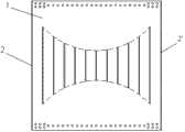
图1为本发明的两边连接不等高开竖缝钢板剪力墙的结构示意图。Fig. 1 is a structural schematic diagram of a steel plate shear wall with unequal heights and vertical seams connected on both sides of the present invention.
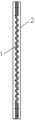
图2为图1的侧视图。FIG. 2 is a side view of FIG. 1 .
图3为竖缝顶点成对称直线的钢板。Fig. 3 is a steel plate with vertical seam vertices forming a symmetrical straight line.
图4为竖缝顶点成对称圆弧的钢板。Fig. 4 is a steel plate with a vertical seam apex forming a symmetrical arc.
图5为左侧加劲肋和带缝钢板的侧视图。Figure 5 is a side view of the left stiffener and the steel plate with seams.
图6为角钢的示意图。Figure 6 is a schematic diagram of angle steel.
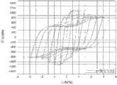
图7为低周往复荷载作用下竖缝递减斜率a=0的剪力墙滞回曲线。Figure 7 is the hysteretic curve of the shear wall with the vertical joint decreasing slope a=0 under the action of low cycle reciprocating load.
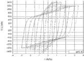
图8为低周往复荷载作用下竖缝递减斜率a=0.4的剪力墙滞回曲线。Figure 8 is the hysteretic curve of the shear wall with the vertical joint decreasing slope a=0.4 under the action of low cycle reciprocating load.
具体实施方式Detailed ways
下面结合附图对本发明作更进一步的说明。The present invention will be further described below in conjunction with the accompanying drawings.
如图1和图2所示,本发明的两边连接侧向加劲不等高开竖缝钢板剪力墙由带缝钢板1、上边缘框架梁3、下边缘框架梁3’、上端角钢4以及下端角钢5组成;带缝钢板1、上边缘框架梁3、下边缘框架梁3’、上端角钢4以及下端角钢5都开设有螺旋栓,如图6所示,在角钢的边角处设有更为密集的螺旋栓,通过高强摩擦型螺栓将上端角钢4和下端角钢5分别与上边缘框架梁3、下边缘框架梁3’连接。同时,上端角钢4和下端角钢5都设置有加劲肋8,使得角钢不容易变形;上端角钢4和下端角钢5还通过螺旋栓分别与带缝钢板1的上端和下端连接。以上框架梁、角钢、带缝钢板重叠的表面采取抛丸处理以形成摩擦面。As shown in Figure 1 and Figure 2, the steel plate shear wall with unequal heights and vertical seams connected on both sides of the present invention is composed of a steel plate with
带缝钢板的左右侧分别左侧加劲肋2和右侧加劲肋2’,其高度与带缝钢板1的高度相同,并且采用两侧交错间隙焊缝连接的方式将左侧加劲肋2和右侧加劲肋2’分别与带缝钢板1的左侧和右侧相连接;劲肋2采用与带缝钢板等厚钢板或型钢,所述型钢截面为槽形、工字形或矩形。The left and right sides of the steel plate with seam are respectively the
如图3和图4所示,带缝钢板1上开设有等距且不等高的竖缝。如图3所示,带缝钢板1上的竖缝等间距布置且开缝高度自带缝钢板外侧向钢板中心成等差数列并保证各缝的中心和钢板的横向中心线重合,竖缝的顶部端点的连线为对称折线;如图4所示,带缝钢板1上的竖缝等间距布置且竖缝的顶部端点的连线为对称圆弧。带缝钢板1上的竖缝由激光切割或等离子切割或水切割而成,缝端部采用圆弧过渡以减小应力集中。As shown in Fig. 3 and Fig. 4, vertical seams of equal distance and unequal height are opened on the steel plate with
为了验证不等高竖缝可以给钢板剪力墙带来更好的性能,进行了有限元分析,主要考察不同的竖缝递减值对性能增益的影响。In order to verify that unequal height vertical joints can bring better performance to steel plate shear walls, a finite element analysis was carried out, mainly investigating the influence of different vertical joint decreasing values on performance gain.
为了考察不同的竖缝递减值,,墙板高度取3m、厚度取15mm,缝宽取15mm,边缘加劲肋取265mm宽,缝间墙肢宽度取156.25mm,最长竖缝长度取1000mm。对比图7中低周往复荷载作用下竖缝递减斜率为a=0(均匀缝)的剪力墙滞回曲线和图8中竖缝递减斜率为a=0.4的不等高竖缝剪力墙的滞回曲线,发现滞回曲线越来越饱满,并且表现出更加优越的耗能性能,同时具有更高的初始刚度和跟大的承载力。In order to investigate different vertical seam decrement values, the height of the wall panel is 3m, the thickness is 15mm, the seam width is 15mm, the edge stiffener is 265mm wide, the wall width between seams is 156.25mm, and the longest vertical seam length is 1000mm. Comparing the hysteretic curve of the shear wall with vertical joint decreasing slope of a=0 (uniform joint) in Figure 7 and the vertical joint shear wall of different heights with vertical joint decreasing slope of a=0.4 in Figure 8 It is found that the hysteretic curve is getting fuller and fuller, and it shows more superior energy dissipation performance, and has higher initial stiffness and higher bearing capacity at the same time.
Claims (5)
Translated fromChinesePriority Applications (1)
| Application Number | Priority Date | Filing Date | Title |
|---|---|---|---|
| CN201310232404.9ACN103410247B (en) | 2013-06-09 | 2013-06-09 | A kind of both sides connection side not contourly opens vertical seam steel plate shear force wall to putting more energy into |
Applications Claiming Priority (1)
| Application Number | Priority Date | Filing Date | Title |
|---|---|---|---|
| CN201310232404.9ACN103410247B (en) | 2013-06-09 | 2013-06-09 | A kind of both sides connection side not contourly opens vertical seam steel plate shear force wall to putting more energy into |
Publications (2)
| Publication Number | Publication Date |
|---|---|
| CN103410247Atrue CN103410247A (en) | 2013-11-27 |
| CN103410247B CN103410247B (en) | 2015-10-21 |
Family
ID=49603284
Family Applications (1)
| Application Number | Title | Priority Date | Filing Date |
|---|---|---|---|
| CN201310232404.9AExpired - Fee RelatedCN103410247B (en) | 2013-06-09 | 2013-06-09 | A kind of both sides connection side not contourly opens vertical seam steel plate shear force wall to putting more energy into |
Country Status (1)
| Country | Link |
|---|---|
| CN (1) | CN103410247B (en) |
Cited By (13)
| Publication number | Priority date | Publication date | Assignee | Title |
|---|---|---|---|---|
| CN103835399A (en)* | 2014-03-10 | 2014-06-04 | 北京工业大学 | Prestress embedded steel plate-concrete combined shear wall |
| CN103835397A (en)* | 2014-03-10 | 2014-06-04 | 北京工业大学 | Prestress slotted steel plate shear wall |
| CN103835394A (en)* | 2014-03-10 | 2014-06-04 | 北京工业大学 | Prestress pored steel plate shear wall |
| CN103835400A (en)* | 2014-03-10 | 2014-06-04 | 北京工业大学 | Prestress steel plate shear wall |
| CN103835398A (en)* | 2014-03-10 | 2014-06-04 | 北京工业大学 | Prestress waveform section steel plate shear wall |
| CN103835395A (en)* | 2014-03-10 | 2014-06-04 | 北京工业大学 | Prestress oblique double-layer folded steel plate shear wall |
| CN103883025A (en)* | 2014-03-11 | 2014-06-25 | 北京工业大学 | Assembling type combination steel plate shear wall |
| CN103883029A (en)* | 2014-03-11 | 2014-06-25 | 北京工业大学 | Assembling type reinforcing steel plate shear wall |
| CN103967166A (en)* | 2014-04-25 | 2014-08-06 | 东南大学 | Low-yield-point steel plate shear wall with two connected edges |
| CN105756227A (en)* | 2014-12-15 | 2016-07-13 | 山东大学 | Multilayer oblique slotted self anti-buckling steel plate shear wall and manufacturing method thereof |
| CN105756229A (en)* | 2014-12-15 | 2016-07-13 | 山东大学 | Multilayer self anti-buckling steel plate shear wall |
| CN106436974A (en)* | 2016-12-07 | 2017-02-22 | 福建工程学院 | Anti-buckling steel plate shear wall with combined vertical seams |
| CN113392446A (en)* | 2021-05-27 | 2021-09-14 | 万翼科技有限公司 | Method, device, equipment and storage medium for generating audit data of shear wall |
- 2013
- 2013-06-09CNCN201310232404.9Apatent/CN103410247B/ennot_activeExpired - Fee Related
Cited By (18)
| Publication number | Priority date | Publication date | Assignee | Title |
|---|---|---|---|---|
| CN103835397A (en)* | 2014-03-10 | 2014-06-04 | 北京工业大学 | Prestress slotted steel plate shear wall |
| CN103835394A (en)* | 2014-03-10 | 2014-06-04 | 北京工业大学 | Prestress pored steel plate shear wall |
| CN103835400A (en)* | 2014-03-10 | 2014-06-04 | 北京工业大学 | Prestress steel plate shear wall |
| CN103835398A (en)* | 2014-03-10 | 2014-06-04 | 北京工业大学 | Prestress waveform section steel plate shear wall |
| CN103835395A (en)* | 2014-03-10 | 2014-06-04 | 北京工业大学 | Prestress oblique double-layer folded steel plate shear wall |
| CN103835399A (en)* | 2014-03-10 | 2014-06-04 | 北京工业大学 | Prestress embedded steel plate-concrete combined shear wall |
| CN103835395B (en)* | 2014-03-10 | 2016-01-13 | 北京工业大学 | A prestressed inclined double-layer folded plate steel plate shear wall |
| CN103835400B (en)* | 2014-03-10 | 2016-05-25 | 北京工业大学 | A kind of pre-stressed steel plate shear wall |
| CN103835399B (en)* | 2014-03-10 | 2016-06-01 | 北京工业大学 | A kind of prestress embedded steel plate concrete composite shear wall |
| CN103883025B (en)* | 2014-03-11 | 2017-05-10 | 北京工业大学 | Assembling type combination steel plate shear wall |
| CN103883025A (en)* | 2014-03-11 | 2014-06-25 | 北京工业大学 | Assembling type combination steel plate shear wall |
| CN103883029A (en)* | 2014-03-11 | 2014-06-25 | 北京工业大学 | Assembling type reinforcing steel plate shear wall |
| CN103967166A (en)* | 2014-04-25 | 2014-08-06 | 东南大学 | Low-yield-point steel plate shear wall with two connected edges |
| CN105756229A (en)* | 2014-12-15 | 2016-07-13 | 山东大学 | Multilayer self anti-buckling steel plate shear wall |
| CN105756227A (en)* | 2014-12-15 | 2016-07-13 | 山东大学 | Multilayer oblique slotted self anti-buckling steel plate shear wall and manufacturing method thereof |
| CN105756227B (en)* | 2014-12-15 | 2017-10-31 | 山东大学 | A kind of oblique fluting of multilayer from anti-buckling steel plate shear force wall and preparation method thereof |
| CN106436974A (en)* | 2016-12-07 | 2017-02-22 | 福建工程学院 | Anti-buckling steel plate shear wall with combined vertical seams |
| CN113392446A (en)* | 2021-05-27 | 2021-09-14 | 万翼科技有限公司 | Method, device, equipment and storage medium for generating audit data of shear wall |
Also Published As
| Publication number | Publication date |
|---|---|
| CN103410247B (en) | 2015-10-21 |
Similar Documents
| Publication | Publication Date | Title |
|---|---|---|
| CN103410247B (en) | A kind of both sides connection side not contourly opens vertical seam steel plate shear force wall to putting more energy into | |
| CN104508220B (en) | The axial surrender delayed support member of type elastoplasticity and vibration-damp steel shelf structure thing | |
| CN207988220U (en) | Combined steel plate shearing force wall | |
| CN202430895U (en) | A butt-connected I-beam with grooved reinforcing plates | |
| CN104805958B (en) | Double-yielding energy-dissipating steel coupling beams applied to combined shear wall structures | |
| CN103696505A (en) | Low-yield-point steel buckling-restrained shearing plate damper | |
| CN103967166A (en) | Low-yield-point steel plate shear wall with two connected edges | |
| CN203129435U (en) | Steel-structured beam/column | |
| CN103174222A (en) | Steel casting modularization panel point for connection of steel pipe column and H-shaped beam | |
| CN103015535A (en) | Rigid connecting structure for H-shaped column in weak shaft direction and H-shaped beam and manufacture method thereof | |
| CN203320734U (en) | Two side-connected and laterally stiffened slit steel plate shear wall with unequal heights | |
| CN110453849A (en) | A longitudinally thickened I-beam | |
| CN204609123U (en) | A kind of Steel concrete compound beam structure | |
| CN103806672B (en) | A kind of existing beam and lacing formula lattice steel column are collided the reinforcement of node | |
| CN103835434B (en) | H profile steel with ribbing and H profile steel xoncrete structure with ribbing | |
| CN108532754B (en) | Twin beams is bent shearing-type accentric support dissipative links, eccentrically braces structure | |
| CN104670522B (en) | Weld joint stress homogenized rock propellant tank cylinder section wall plate | |
| CN203094073U (en) | Cold bend channel-steel-shaped beam for railway wagon | |
| CN203821630U (en) | Two-sided connection type low yield point steel plate shear wall | |
| CN205421713U (en) | Last circular down rectangle edge of a wing steel reinforced concrete complex carrier bar that excels in | |
| CN103437500A (en) | C-shaped steel-concrete combined compression flange and corrugated web combined box girder | |
| CN206000024U (en) | A kind of dust collector box body | |
| CN202658799U (en) | Rectangular steel pipe concrete column with constraint draw bars and stiffening bands | |
| CN206000025U (en) | A kind of dust collector box body | |
| CN205874945U (en) | Novel U rib |
Legal Events
| Date | Code | Title | Description |
|---|---|---|---|
| C06 | Publication | ||
| PB01 | Publication | ||
| C10 | Entry into substantive examination | ||
| SE01 | Entry into force of request for substantive examination | ||
| C14 | Grant of patent or utility model | ||
| GR01 | Patent grant | ||
| CF01 | Termination of patent right due to non-payment of annual fee | ||
| CF01 | Termination of patent right due to non-payment of annual fee | Granted publication date:20151021 |