CN103406162A - Accurate droplet generation method based on electrowetting-on-dielectric digital microfluidic chip - Google Patents
Accurate droplet generation method based on electrowetting-on-dielectric digital microfluidic chipDownload PDFInfo
- Publication number
- CN103406162A CN103406162ACN2013102810437ACN201310281043ACN103406162ACN 103406162 ACN103406162 ACN 103406162ACN 2013102810437 ACN2013102810437 ACN 2013102810437ACN 201310281043 ACN201310281043 ACN 201310281043ACN 103406162 ACN103406162 ACN 103406162A
- Authority
- CN
- China
- Prior art keywords
- electrode
- electrode group
- electrodes
- drop
- micro
- Prior art date
- Legal status (The legal status is an assumption and is not a legal conclusion. Google has not performed a legal analysis and makes no representation as to the accuracy of the status listed.)
- Pending
Links
Images

Landscapes
- Physical Or Chemical Processes And Apparatus (AREA)
Abstract
Translated fromChinese
Description
Translated fromChinese技术领域technical field
本发明属于数字微流技术领域,具体涉及基于介质电润湿数字微流芯片的精准液滴产生方法。The invention belongs to the technical field of digital microfluidics, and in particular relates to a method for generating precise droplets based on a dielectric electrowetting digital microfluidic chip.
背景技术Background technique
基于介质电润湿效应的数字微流技术是指通过在介质结构上施加电压改变液滴在介质表面的润湿性能从而改变液滴与界面接触角以进一步对离散液滴进行操控的微流技术,它具有驱动方式简单、驱动力强、操控方便、自动化程度高等许多优点,是数字微流领域的主流技术,在LOC领域中具有非常好的发展前景。基于介质电润湿的数字微流芯片通常包括四个部分,施加驱动信号的电极层、充当电容作用的介质层、降低表面能量的疏水层以及操控对象液滴。其中,驱动电极是芯片功能中非常灵活的一部分,通过不同的电极排布、形状、尺寸等设计可以满足不同的液滴驱动功能。The digital microfluidic technology based on the dielectric electrowetting effect refers to the microfluidic technology that changes the wettability of the droplet on the surface of the medium by applying a voltage on the dielectric structure, thereby changing the contact angle between the droplet and the interface to further manipulate the discrete droplet. , it has many advantages such as simple driving method, strong driving force, convenient operation, and high degree of automation. It is the mainstream technology in the field of digital microfluidics and has very good development prospects in the field of LOC. A digital microfluidic chip based on dielectric electrowetting usually includes four parts, an electrode layer that applies a driving signal, a dielectric layer that acts as a capacitor, a hydrophobic layer that reduces surface energy, and manipulates object droplets. Among them, the driving electrode is a very flexible part of the chip function, and different droplet driving functions can be satisfied through different electrode arrangements, shapes, sizes and other designs.
在数字微流体技术中,由于操控对象是微尺度液滴,所以对液滴的量的控制有较高要求,特别是在生物化学应用中,液滴大小的精准性直接关系到反应检测的结果,精准的液滴产生、控制技术是微流体芯片商业化应用非常重要的一个环节。而在基于介质电润湿的数字微流体芯片中,普通方法的液滴产生并不能非常精准,液滴的大小往往有10%以内的误差,这主要和其液滴产生原理及其结构有关。在介质电润湿数字微流体芯片中,液滴的产生包括两个过程,一是驱动电极施加信号从蓄液池中拉出液滴,二是液滴拉出后,某个驱动电极去电使液滴部分发生断裂从而产生液滴。在传统芯片中,液滴的产生电极与驱动电极都是一样的,这样在液滴产生过程中,液滴的不规则形变,断裂位置的不确定以及快速断裂造成的震动等因素都会影响最终产生液滴的大小。因此,传统介质电润湿数字微流领域中,产生液滴的不精准是其商业化应用的重要瓶颈,虽然有文章报道可以加上连续微流精准控制泵给数字微流芯片提供精确液滴,但这显然不符合芯片实验室的集成性和便携性。因此,如何提高介质电润湿数字微流芯片液滴产生的精准性是一个亟需解决的问题。In digital microfluidics technology, since the manipulated objects are micro-scale droplets, there are high requirements for the control of the amount of droplets, especially in biochemical applications, where the accuracy of droplet size is directly related to the results of reaction detection , accurate droplet generation and control technology is a very important link in the commercial application of microfluidic chips. In the digital microfluidic chip based on dielectric electrowetting, the droplet generation by the common method is not very accurate, and the size of the droplet often has an error within 10%, which is mainly related to the droplet generation principle and structure. In the dielectric electrowetting digital microfluidic chip, the generation of droplets includes two processes, one is to apply signals to the driving electrodes to pull out the droplets from the liquid reservoir, and the other is to de-energize a certain driving electrode after the droplets are pulled out. Partial breakage of the droplet occurs to produce a droplet. In the traditional chip, the droplet generation electrode and the driving electrode are the same, so that in the droplet generation process, the irregular deformation of the droplet, the uncertainty of the fracture position, and the vibration caused by the rapid fracture will affect the final generation. The size of the droplet. Therefore, in the field of traditional dielectric electrowetting digital microfluidics, the inaccuracy of droplet generation is an important bottleneck for its commercial application, although there are reports that continuous microflow precision control pumps can be added to digital microfluidic chips to provide precise droplets. , but this is obviously not in line with the integration and portability of the lab-on-a-chip. Therefore, how to improve the accuracy of droplet generation in dielectric electrowetting digital microfluidic chips is an urgent problem to be solved.
发明内容Contents of the invention
本发明目的在于提供一种精准高的基于介质电润湿数字微流芯片的液滴产生方法。The purpose of the present invention is to provide a precise and high-precision droplet generation method based on a dielectric electrowetting digital microfluidic chip.
本发明目的在于提供一种基于介质电润湿数字微流芯片的液滴产生方法,主要通过数字微流芯片驱动电极的设计和驱动信号操作来实现,在液滴分裂产生处,以特殊的微细电极组成电极组代替传统的单个电极,电极组整体使用时与常规电极一致,可实现液滴拉出,而电极组内微细电极单独操作时可实现液滴平稳、精准分裂。更准确的,当液滴分裂时,不是整个电极组去电,而是电极组内的微细电极依次缓慢去电,这样避免了液滴不规则形变,而且增加了液滴分裂位置的确定性,这样每次产生的液滴大小就能保持一致,可以大大增加其精准性。具体的,本发明方法包括以下4种技术方案:The purpose of the present invention is to provide a droplet generation method based on a dielectric electrowetting digital microfluidic chip, which is mainly realized by the design of the driving electrode of the digital microfluidic chip and the operation of the driving signal. Electrode composition The electrode group replaces the traditional single electrode. When the electrode group is used as a whole, it is consistent with the conventional electrode, which can realize the droplet pulling, and the micro-electrodes in the electrode group can realize the stable and precise splitting of the droplet when operated alone. More precisely, when the droplet splits, it is not the entire electrode group that is de-energized, but the fine electrodes in the electrode group are de-electrified slowly one by one, which avoids the irregular deformation of the droplet and increases the certainty of the splitting position of the droplet. In this way, the size of the droplets generated each time can be kept consistent, which can greatly increase its accuracy. Concretely, the inventive method comprises following 4 kinds of technical schemes:
第1种,电极组由若干竖条状微细电极组成,呈矩形形状。微细电极数目和横向尺寸并不限定,如图1(a)所示,一般微细电极数目为3-8根,图1(a)中,画出5根。在需要液滴分裂产生时,将电极组内微细电极依次由内向外“去电”,即先去掉电极组中心微细电极的驱动信号,然后依次向外对称地去掉其余微细电极信号,这样在电极组上,由于中心微细电极没有驱动信号,液滴就会先从中心部分开始收缩,然后向两边扩展,哑铃状液滴中心不断变细,最后液滴中心部分达到最细,从而在电极组中心处分裂,实现液滴的产生;In the first type, the electrode group is composed of a number of vertical strip-shaped micro-electrodes in a rectangular shape. The number and lateral size of the micro-electrodes are not limited, as shown in Figure 1(a), the number of micro-electrodes is generally 3-8, and in Figure 1(a), 5 are drawn. When it is necessary to split the droplet, the micro-electrodes in the electrode group are "de-energized" from the inside to the outside in turn, that is, the driving signal of the micro-electrode in the center of the electrode group is removed first, and then the remaining micro-electrode signals are removed symmetrically outward, so that the electrode On the group, since there is no driving signal for the central micro-electrode, the droplet will first shrink from the center and then expand to both sides. Split at the place to realize the generation of droplets;
第2种,电极组由若干横条状微细电极组成,呈矩形形状。微细电极数目和竖向尺寸并不限定,如图1(b)所示,一般微细电极数目为3-8根,图1(b)中,画出5根。在需要液滴分裂产生时,将电极组内微细电极依次由外向内“去电”,即对称地先去掉电极组外围微细电极的驱动信号,然后依次向内去掉其余微细电极信号,这样位于电极组上的液滴由于边缘首先不受驱动信号控制,故其体积会不断收缩,形成哑铃状,最终在电极组中心处达到最细,当电极组驱动信号完全去除时,液滴最细处分裂,实现液滴产生;In the second type, the electrode group is composed of a number of horizontal strip-shaped micro-electrodes in a rectangular shape. The number and vertical size of the micro-electrodes are not limited, as shown in Figure 1(b), generally the number of micro-electrodes is 3-8, and in Figure 1(b), 5 are drawn. When droplet splitting is required, the micro-electrodes in the electrode group are “de-energized” from the outside to the inside in turn, that is, the driving signals of the micro-electrodes on the periphery of the electrode group are symmetrically removed first, and then the remaining micro-electrode signals are removed inwards in turn, so that the electrodes located in the electrode group Because the edge of the droplet on the group is not controlled by the driving signal first, its volume will continue to shrink, forming a dumbbell shape, and finally reaching the thinnest at the center of the electrode group. When the driving signal of the electrode group is completely removed, the droplet splits at the thinnest point , to achieve droplet generation;
第3种,电极组由4个三角形电极组成,4个三角形顶端相对分上、下、左、右排布,使电极组为与常规电极一致的矩形形状,实际上就是把一个矩形产生电极沿对角线部分分成4个微细电极。在需要液滴分裂产生时,先对上、下2个三角形电极同时“去电”,再对左、右三角形电极同时“去电”。当同时去掉“上、下”2个三角形电极的驱动信号时,电极组上液滴由于上下边缘部分不受驱动信号控制,而收缩集中在电极组中心处;其次,当同时去掉“左、右”2个三角形电极的驱动信号即电极组驱动信号完全去除时,哑铃状液滴在中心发生分裂,从而实现液滴的产生;In the third type, the electrode group is composed of 4 triangular electrodes, and the tops of the 4 triangles are relatively arranged up, down, left, and right, so that the electrode group has a rectangular shape consistent with the conventional electrodes. In fact, a rectangular electrode is generated along the The diagonal part is divided into 4 fine electrodes. When droplet splitting is required, the upper and lower triangular electrodes are first "de-energized" at the same time, and then the left and right triangular electrodes are "de-energized" at the same time. When the driving signals of the "upper and lower" triangular electrodes are removed at the same time, the droplets on the electrode group shrink and concentrate at the center of the electrode group because the upper and lower edges are not controlled by the driving signals; secondly, when the "left and right" are removed at the same time "When the driving signal of the two triangular electrodes, that is, the driving signal of the electrode group is completely removed, the dumbbell-shaped droplet splits in the center, thereby realizing the generation of the droplet;
第4种,电极组由两个半圆电极和一个哑铃状圆凹电极组成,三个电极紧密排布以使电极组为与常规电极一致的矩形形状,其中2个半圆电极分别位于“上、下”位置,园弧部分相对,哑铃状电极夹于两半圆电极的园弧中间,这种电极组结构更符合液滴的分裂形状,从而增加分裂时的平稳性。在需要液滴分裂产生时,先对“上、下”2个半圆电极同时“去电”,然后再对中间电极“去电”,即先同时去掉位于“上、下”位置的半圆电极驱动信号,使液滴向内收缩,形成和底部电极一样的哑铃状,当最后去掉中间的哑铃状电极的驱动信号时,液滴会在中心发生分裂,从而实现液滴产生。In the fourth type, the electrode group consists of two semicircular electrodes and a dumbbell-shaped circular concave electrode. The three electrodes are closely arranged so that the electrode group has a rectangular shape consistent with conventional electrodes, and the two semicircular electrodes are respectively located in the "upper and lower ” position, the arc part is opposite, and the dumbbell-shaped electrode is sandwiched between the arcs of the two semicircular electrodes. This electrode group structure is more in line with the splitting shape of the droplet, thereby increasing the stability of splitting. When droplet splitting is required, the "upper and lower" two semicircular electrodes are "de-energized" at the same time, and then the middle electrode is "de-energized", that is, the semi-circular electrodes located at the "upper and lower" positions are removed at the same time. The signal makes the droplet shrink inward, forming the same dumbbell shape as the bottom electrode. When the driving signal of the dumbbell-shaped electrode in the middle is finally removed, the droplet will split in the center, thereby realizing droplet generation.
本发明中,4种情况的微细电极组成的电极组尺寸(包括微细电极间间隙)应当与邻近常规驱动电极一致,更为具体地,可以看做将一个常规驱动电极分解为本发明的四种情况微细电极,这样的好处是本发明的液滴产生技术电极尺寸与传统常规芯片兼容,只需对某一个常规电极进行改进设计即可,实现简便。In the present invention, the electrode group size (including the gap between the micro-electrodes) composed of the four kinds of micro-electrodes should be consistent with the adjacent conventional driving electrodes. More specifically, it can be seen as decomposing a conventional driving electrode into four types of the present invention In the case of fine electrodes, the advantage of this is that the electrode size of the droplet generation technology of the present invention is compatible with traditional conventional chips, and it is only necessary to improve the design of a certain conventional electrode, which is easy to implement.
本发明第1、第2种情况所述“微细”电极指的是该电极尺寸的宽度相比邻近常规驱动电极要小的多,其宽度约为邻近常规驱动电极的十分之一到三分之一;本发明第3种情况的4个三角微细电极尺寸是一样的,其组合整体(包括微细电极间间隙)与邻近常规电极尺寸一致;本发明第4中情况中,两个半圆微细电极和一个哑铃状圆凹电极组成的整体尺寸(包括微细电极间间隙)与邻近常规电极尺寸一致,并满足,圆凹电极最细处宽度不小于常规电极尺寸的十分之一。 The "fine" electrode mentioned in the first and second cases of the present invention refers to that the width of the electrode size is much smaller than that of the adjacent conventional drive electrode, and its width is about one tenth to one third of the adjacent conventional drive electrode. One; the size of the 4 triangular micro-electrodes in the 3rd case of the present invention is the same, and its combined whole (including the gap between the micro-electrodes) is consistent with the size of the adjacent conventional electrodes; in the 4th case of the present invention, the two semicircular micro-electrodes The overall size (including the gap between the fine electrodes) composed of a dumbbell-shaped circular concave electrode is consistent with the size of the adjacent conventional electrode, and it is satisfied that the width of the thinnest part of the circular concave electrode is not less than one tenth of the size of the conventional electrode. the
本发明中,由于使用微细电极,可以对液滴进行多步操作,通过微细电极的依次缓慢去电可以使液滴收缩的形状趋势与电极去电趋势一致,这样保证液滴不受扰动以及分裂位置固定,使每次产生的液滴大小一致,这是本发明的关键之处。In the present invention, due to the use of micro-electrodes, the liquid droplets can be operated in multiple steps, and the shape trend of the shrinkage of the liquid droplets can be consistent with the trend of the electrode de-electricity through the sequential and slow de-electrification of the micro-electrodes, so as to ensure that the liquid droplets are not disturbed and split. The location is fixed so that the size of the droplets produced each time is consistent, which is the key point of the present invention.
本发明中,电极组与邻近电极之间,电极组内微细电极之间是电气隔离的,其隔离间隙与微流体芯片其他电极间隙保持一致。In the present invention, the electrode group is electrically isolated from adjacent electrodes, and the fine electrodes in the electrode group are electrically isolated, and the isolation gap is consistent with other electrode gaps of the microfluidic chip.
本发明中,微细电极组成的电极组尺寸应当与驱动电极匹配,以满足芯片的通用性,并使产生的液滴能够被后续驱动电极操控。In the present invention, the size of the electrode group composed of micro-electrodes should match the driving electrodes, so as to meet the versatility of the chip and enable the generated droplets to be manipulated by subsequent driving electrodes.
本发明中,所述微细电极“去电”是有对称性和时序性的,以电极组中心为轴两边对称的微细电极都是同步“去电”,以保证液滴收缩在电极组中心,而且不同微细电极的“去电”是先后有序的,微细电极间的去电时间间隔并不限定,但应保证一定时间以使液滴分裂平稳。In the present invention, the "de-energization" of the micro-electrodes is symmetrical and sequential, and the micro-electrodes that are symmetrical on both sides with the center of the electrode group as the axis are all synchronously "de-energized" to ensure that the droplet shrinks in the center of the electrode group. Moreover, the "de-electrification" of different micro-electrodes is sequential, and the time interval of de-electrification between micro-electrodes is not limited, but a certain time should be guaranteed to make the droplet split smoothly.
本发明中,所述“液滴”是指能用于电润湿驱动的溶液滴,其成分可以是单一的生物样品、化学溶液等,也可以是多成分组成,如外面包裹着一层油膜的液滴等,其大小并不限定,可以为次微微升到若干毫升之间。In the present invention, the "droplet" refers to a solution drop that can be driven by electrowetting, and its composition can be a single biological sample, chemical solution, etc., or it can be composed of multiple components, such as a layer of oil film wrapped outside The size of the liquid droplets is not limited, and can be between subpicoliters and several milliliters.
本发明中,所述“驱动电极”是指芯片实施时,对应电极的电压被置成不为0以使电润湿驱动能够发生,所述“接地电极”是指芯片实施时,对应电极的电压被置成0或与0足够接近。In the present invention, the "driving electrode" refers to that the voltage of the corresponding electrode is set to be non-zero when the chip is implemented, so that the electrowetting drive can occur, and the "ground electrode" refers to the voltage of the corresponding electrode when the chip is implemented. The voltage is set to 0 or close enough to 0.
本发明中,所述的“上下”指的是与液滴运动垂直的方向,“左右”是指与液滴运动平行的方向,“去电”是指驱动电极驱动电压信号的去除。In the present invention, the "up and down" refers to the direction perpendicular to the movement of the droplet, "left and right" refers to the direction parallel to the movement of the droplet, and "de-energization" refers to the removal of the driving voltage signal of the driving electrode.
本发明中,所述“在……上”或“位于……上”可以指某一部分直接位于另一部分上,两部分是接触的,也可以是指有某一部分在物理空间上位于另一部分上,两部分之间还有其它部分。In the present invention, the "on" or "located on" may mean that a certain part is directly on the other part, and the two parts are in contact, or it may mean that a certain part is located on the other part in physical space , there are other parts between the two parts.
本发明提供的技术方案是基于电极的设计及驱动信号操作,因此能够应用于各种结构的介质电润湿数字微流控芯片中。The technical solution provided by the invention is based on electrode design and driving signal operation, so it can be applied to dielectric electrowetting digital microfluidic chips with various structures.
本发明的创新在于利用微细电极组成电极组作为液滴产生的分裂电极,并通过微细电极依次缓慢去电,以使液滴能够平稳收缩最终在固定位置分裂,从而确保了液滴产生的精准性。。The innovation of the present invention lies in the use of micro-electrodes to form an electrode group as the splitting electrode for droplet generation, and the micro-electrodes are slowly de-energized in turn, so that the droplet can shrink smoothly and finally split at a fixed position, thereby ensuring the accuracy of droplet generation . .
本发明提供的精准液滴产生方法具有如下显著优势:The precise droplet generation method provided by the present invention has the following significant advantages:
(a)直接利用驱动电极形状设计和信号操控,无需额外部件,实现简单,可以配置于传统的各种芯片结构,适用范围广;(a) Directly use the driving electrode shape design and signal control, without additional components, easy to implement, can be configured in various traditional chip structures, and have a wide range of applications;
(b)能够增加液滴产生的平稳性,不仅可以大大提高每次液滴产生的精度,而且可以减少失效的发生,增加了芯片的稳定性;(b) It can increase the stability of droplet generation, which can not only greatly improve the accuracy of each droplet generation, but also reduce the occurrence of failure and increase the stability of the chip;
(c)解决了传统领域的瓶颈,精确液滴的产生有利于大大扩展芯片的商业化应用。(c) The bottleneck in the traditional field is solved, and the generation of precise droplets is conducive to greatly expanding the commercial application of the chip.
附图说明Description of drawings
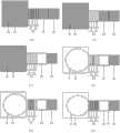
图1是根据本发明的精确液滴产生方法对应的4种电极配置示意图。其中,(a)为第一种,(b)为第二种,(c)为第三种,(d)为第四种。 FIG. 1 is a schematic diagram of four electrode configurations corresponding to the precise droplet generation method according to the present invention. Among them, (a) is the first type, (b) is the second type, (c) is the third type, and (d) is the fourth type. the
图2是根据本发明的精确液滴产生方法的一种芯片实现结构示意图。Fig. 2 is a schematic diagram of a chip implementation structure of the precise droplet generation method according to the present invention.
图3是使用本发明的精确液滴产生方法的一种电极配置来实现具体的液滴产生过程示意图。Fig. 3 is a schematic diagram of a specific droplet generation process achieved by using an electrode configuration of the precise droplet generation method of the present invention.
具体实施方式Detailed ways
本发明提供的基于介质电润湿数字微流体芯片的精准液滴产生技术是通过电极设计和驱动信号控制来实现的,因此可以有多种配置方式,可以配置于各种数字微流芯片中。应当指出,本实施方式是为了说明目的而提供,而不在意以任何方式限制本发明的范围。The precise droplet generation technology based on the dielectric electrowetting digital microfluidic chip provided by the present invention is realized through electrode design and driving signal control, so it can have multiple configuration methods and can be configured in various digital microfluidic chips. It should be noted that this embodiment is provided for illustrative purposes and is not intended to limit the scope of the present invention in any way.
本发明的精确液滴产生方法,对应的4种电极配置如图1所示。即在蓄液池电极E1与常规驱动电极E3、E4之间设置了特殊电极组E2,这4种电极共同组成液滴产生电极结构。当电极组内微细电极施加相应操控时,液滴D形成哑铃状结构,并在电极组中心达到最细。图(a)中,竖条状微细电极E21-E25组成电极组E2,5根竖条状微细电极E21-E25的长度与常规驱动电极E3的宽度一致。使液滴分裂时,只需将电极组由内向外去电,如先将微细电极E23去电,其次E22、E24去电,最后E21、E25去电即可完成液滴平稳产生;图(b)中,横条状微细电极E21-E25组成电极组E2,该电极组E2的宽度与常规驱动电极E3的宽度一致。使液滴分裂时,只需将电极组由外而内去电,如先将微细电极E21、E25同时去电,其次E22、E24同时去电,最后E23去电即可完成液滴平稳产生;图(c)中,4个三角形电极E21-E24的4个角两两相对组成矩形电极组E2,该矩形电极组E2的宽度与常规驱动电极E3的宽度一致。使液滴分裂时,只需将电极组先上下去电,再左右去电,如先将微细电极E22、E23同时去电,其次E21、E24同时去电即可完成液滴产生;图(d)中,两个半圆微细电极E21、E23和一个哑铃状圆凹电极E22紧密排布组成矩形电极组E2,即两个半圆微细电极E21、E23的圆弧部分相对排布,哑铃状圆凹电极E22位于两个半圆微细电极E21、E23圆弧的中间。矩形电极组E2的宽度与常规驱动电极E3的宽度一致。使液滴分裂时,只需将电极组由内而外去电,如先将微细电极E21、E23同时去电,再将电极E22去电即可完成液滴产生。The four electrode configurations corresponding to the precise droplet generation method of the present invention are shown in FIG. 1 . That is, a special electrode group E2 is set between the liquid storage battery electrode E1 and the conventional driving electrodes E3 and E4, and these four electrodes together form a droplet generating electrode structure. When the micro-electrodes in the electrode group are controlled accordingly, the droplet D forms a dumbbell-shaped structure, and reaches the thinnest in the center of the electrode group. In figure (a), the vertical strip-shaped micro-electrodes E21-E25 form the electrode group E2, and the length of the five vertical strip-shaped micro-electrodes E21-E25 is consistent with the width of the conventional driving electrode E3. When splitting the droplets, it is only necessary to electrify the electrode group from the inside to the outside. For example, the fine electrode E23 is firstly electrified, followed by E22, E24, and finally E21, E25 to complete the stable generation of droplets; Fig. (b ), the horizontal strip-shaped fine electrodes E21-E25 form an electrode group E2, and the width of the electrode group E2 is consistent with the width of the conventional driving electrode E3. When splitting the droplets, it is only necessary to electrify the electrode group from the outside to the inside. For example, first electrify the micro-electrodes E21 and E25 at the same time, then electrify E22 and E24 at the same time, and finally electrify E23 to complete the stable generation of droplets; In the figure (c), the four corners of the four triangular electrodes E21-E24 face each other to form a rectangular electrode group E2, and the width of the rectangular electrode group E2 is consistent with the width of the conventional driving electrode E3. When splitting the droplet, you only need to power up and down the electrode group first, and then power down the left and right sides. For example, firstly de-energize the micro-electrodes E22 and E23 at the same time, and then de-energize the E21 and E24 at the same time to complete the droplet generation; Figure (d ), two semicircular fine electrodes E21, E23 and a dumbbell-shaped circular concave electrode E22 are closely arranged to form a rectangular electrode group E2, that is, the arc parts of the two semicircular fine electrodes E21 and E23 are arranged oppositely, and the dumbbell-shaped circular concave electrode E22 is located in the middle of the arcs of the two semicircular micro-electrodes E21 and E23. The width of the rectangular electrode group E2 is consistent with the width of the conventional driving electrodes E3. When splitting the droplets, it is only necessary to electrify the electrode group from the inside to the outside. For example, first electrify the micro-electrodes E21 and E23 at the same time, and then electrify the electrode E22 to complete the generation of droplets.
本发明第1、第2种情况所述“微细”电极指的是该电极尺寸的宽度相比邻近常规驱动电极要小的多,其宽度约为邻近常规驱动电极的十分之一到三分之一;本发明第3种情况的4个三角微细电极尺寸是一种的,其组合整体(包括微细电极间间隙)与邻近常规电极尺寸一致;本发明第4中情况中,两个半圆微细电极和一个哑铃状圆凹电极组成的整体尺寸(包括微细电极间间隙)与邻近常规电极尺寸一致,应当满足,圆凹电极最细处宽度不小于常规电极尺寸的十分之一。The "fine" electrode mentioned in the first and second cases of the present invention refers to that the width of the electrode size is much smaller than that of the adjacent conventional drive electrode, and its width is about one tenth to one third of the adjacent conventional drive electrode. One; the size of the four triangular micro-electrodes in the third case of the present invention is one, and its combined whole (including the gap between the micro-electrodes) is consistent with the size of the adjacent conventional electrodes; in the fourth case of the present invention, the two semicircle micro-electrodes The overall size of the electrode and a dumbbell-shaped concave electrode (including the gap between the fine electrodes) is consistent with the size of the adjacent conventional electrode, and it should be satisfied that the width of the thinnest part of the concave electrode is not less than one tenth of the size of the conventional electrode.
基于本发明的精确液滴产生方法的一种芯片实现结构示意图如图2所示,在基板101上为本发明的蓄液池电极E1、常规驱动电极E3、E4和特殊电极组E2。应当说明,本说明书只简单选取数字微流芯片中液滴产生主要部分为例,实际芯片中可以有更多更复杂的驱动电极。在电极上有介质层102,其上置有疏水层103。基板101、电极层E1-E4、介质层102及疏水层103共同构成了器件下极板201。在下极板上为驱动的液滴D0、D1,液滴之上为疏水层104,疏水层上置有接地电极105,其上为绝缘基板106。疏水层104、地电极105、上基板106共同构成了器件的上极板202。本发明仅以此普通双极板芯片为例说明本发明技术的实现。A schematic diagram of a chip implementation structure based on the precise droplet generation method of the present invention is shown in FIG. 2 . On the
基于本发明的精确液滴产生方法的一种电极配置来实现具体的液滴产生过程如图3所示。电极由蓄液池电极E1、常规驱动电极E3、E4和特殊产生电极组E2组成,其中电极组E2以图2中第一种为例,即由竖条状微细电极E21-E25组成。芯片的实施方式如图2所示。开始时,液滴D0位于蓄液池E1之上,如图3(a);当电极组E2施加驱动信号时,液滴从蓄液池E1拉出,覆盖在电极E2之上,如图3(b);其后对电极E3施加驱动信号又使液滴覆盖在电极E2、E3之上,完成液滴的拉出过程,如图3(c);紧接着是液滴的分裂产生过程:首先微细电极E23去电使液滴在其上向内微小收缩,如图3(d);然后微细电极E22、E24也去电,使液滴在其实进一步收缩形成哑铃状,如图3(e);最后,微细电极E21、E25去电使电极组E2全部去电使其上液滴收缩到最小并在中心分裂。以上过程即实现了本发明的精确液滴产生。An electrode configuration based on the precise droplet generation method of the present invention to realize a specific droplet generation process is shown in FIG. 3 . The electrodes are composed of liquid storage battery electrode E1, conventional drive electrodes E3, E4, and special generation electrode group E2. The electrode group E2 is composed of vertical strip micro-electrodes E21-E25, taking the first one in Figure 2 as an example. The implementation of the chip is shown in Figure 2. At the beginning, the droplet D0 is located on the liquid reservoir E1, as shown in Figure 3(a); when the electrode group E2 applies a driving signal, the droplet is pulled out from the liquid reservoir E1 and covers the electrode E2, as shown in Figure 3 (b); then apply a driving signal to the electrode E3 and make the droplet cover the electrodes E2 and E3 to complete the pull-out process of the droplet, as shown in Figure 3(c); followed by the splitting process of the droplet: First, the fine electrode E23 is de-energized to make the liquid drop shrink slightly inward, as shown in Figure 3(d); then the micro-electrodes E22 and E24 are also de-energized, so that the liquid drop further shrinks to form a dumbbell shape, as shown in Figure 3(e ); Finally, the micro-electrodes E21 and E25 are de-energized so that the entire electrode group E2 is de-energized so that the upper droplet shrinks to a minimum and splits in the center. The above process realizes the accurate droplet generation of the present invention.
Claims (3)
Priority Applications (1)
| Application Number | Priority Date | Filing Date | Title |
|---|---|---|---|
| CN2013102810437ACN103406162A (en) | 2013-07-05 | 2013-07-05 | Accurate droplet generation method based on electrowetting-on-dielectric digital microfluidic chip |
Applications Claiming Priority (1)
| Application Number | Priority Date | Filing Date | Title |
|---|---|---|---|
| CN2013102810437ACN103406162A (en) | 2013-07-05 | 2013-07-05 | Accurate droplet generation method based on electrowetting-on-dielectric digital microfluidic chip |
Publications (1)
| Publication Number | Publication Date |
|---|---|
| CN103406162Atrue CN103406162A (en) | 2013-11-27 |
Family
ID=49599231
Family Applications (1)
| Application Number | Title | Priority Date | Filing Date |
|---|---|---|---|
| CN2013102810437APendingCN103406162A (en) | 2013-07-05 | 2013-07-05 | Accurate droplet generation method based on electrowetting-on-dielectric digital microfluidic chip |
Country Status (1)
| Country | Link |
|---|---|
| CN (1) | CN103406162A (en) |
Cited By (9)
| Publication number | Priority date | Publication date | Assignee | Title |
|---|---|---|---|---|
| CN104007548A (en)* | 2014-05-26 | 2014-08-27 | 华南师范大学 | Manufacturing method of electro-wetting displayer |
| CN104841499A (en)* | 2015-04-24 | 2015-08-19 | 复旦大学 | Paper-based digital micro-fluidic device |
| CN105797792A (en)* | 2016-03-28 | 2016-07-27 | 南京理工大学 | Driving method for low-voltage medium liquid drops on digital microfluidic chip |
| CN105854117A (en)* | 2016-03-28 | 2016-08-17 | 南京理工大学 | Precise administration infusion device based on electrowetting on dielectric |
| CN109603931A (en)* | 2018-09-28 | 2019-04-12 | 苏州奥素液芯电子科技有限公司 | A kind of electrowetting dielectric drop actuation means and its manufacturing method |
| WO2020000352A1 (en)* | 2018-06-29 | 2020-01-02 | Boe Technology Group Co., Ltd. | Digital microfluidic device, microfluidic device, lab-on-a-chip device, digital microfluidic method, and method of fabricating digital microfluidic device |
| CN113203607A (en)* | 2020-01-15 | 2021-08-03 | 佛山奥素博新科技有限公司 | Preparation of samples on electrowetting-on-dielectric devices |
| WO2022134035A1 (en)* | 2020-12-25 | 2022-06-30 | 京东方科技集团股份有限公司 | Microfluidic substrate, and microfluidic apparatus and driving method therefor |
| WO2023103136A1 (en)* | 2021-12-07 | 2023-06-15 | 澳门大学 | Droplet generation method based on electrowetting phenomenon, and application thereof |
Citations (1)
| Publication number | Priority date | Publication date | Assignee | Title |
|---|---|---|---|---|
| CN101945767A (en)* | 2007-12-23 | 2011-01-12 | 先进液体逻辑公司 | Droplet actuator configuration and method of directing droplet operations |
- 2013
- 2013-07-05CNCN2013102810437Apatent/CN103406162A/enactivePending
Patent Citations (1)
| Publication number | Priority date | Publication date | Assignee | Title |
|---|---|---|---|---|
| CN101945767A (en)* | 2007-12-23 | 2011-01-12 | 先进液体逻辑公司 | Droplet actuator configuration and method of directing droplet operations |
Cited By (14)
| Publication number | Priority date | Publication date | Assignee | Title |
|---|---|---|---|---|
| CN104007548A (en)* | 2014-05-26 | 2014-08-27 | 华南师范大学 | Manufacturing method of electro-wetting displayer |
| CN104841499A (en)* | 2015-04-24 | 2015-08-19 | 复旦大学 | Paper-based digital micro-fluidic device |
| CN105854117B (en)* | 2016-03-28 | 2022-03-15 | 南京理工大学 | Accurate infusion set that doses based on electrowetting on medium |
| CN105854117A (en)* | 2016-03-28 | 2016-08-17 | 南京理工大学 | Precise administration infusion device based on electrowetting on dielectric |
| CN105797792B (en)* | 2016-03-28 | 2017-12-12 | 南京理工大学 | A kind of low-voltage medium drop driving method on digital microcurrent-controlled chip |
| CN105797792A (en)* | 2016-03-28 | 2016-07-27 | 南京理工大学 | Driving method for low-voltage medium liquid drops on digital microfluidic chip |
| WO2020000352A1 (en)* | 2018-06-29 | 2020-01-02 | Boe Technology Group Co., Ltd. | Digital microfluidic device, microfluidic device, lab-on-a-chip device, digital microfluidic method, and method of fabricating digital microfluidic device |
| US11325128B2 (en) | 2018-06-29 | 2022-05-10 | Boe Technology Group Co., Ltd. | Digital microfluidic device, microfluidic device, lab-on-a-chip device, digital microfluidic method, and method of fabricating digital microfluidic device |
| CN109603931A (en)* | 2018-09-28 | 2019-04-12 | 苏州奥素液芯电子科技有限公司 | A kind of electrowetting dielectric drop actuation means and its manufacturing method |
| CN109603931B (en)* | 2018-09-28 | 2021-07-27 | 广东奥素液芯微纳科技有限公司 | Electrowetting dielectric liquid drop actuating device and manufacturing method thereof |
| CN113203607A (en)* | 2020-01-15 | 2021-08-03 | 佛山奥素博新科技有限公司 | Preparation of samples on electrowetting-on-dielectric devices |
| WO2022134035A1 (en)* | 2020-12-25 | 2022-06-30 | 京东方科技集团股份有限公司 | Microfluidic substrate, and microfluidic apparatus and driving method therefor |
| EP4151312A4 (en)* | 2020-12-25 | 2023-07-12 | BOE Technology Group Co., Ltd. | Microfluidic substrate, and microfluidic apparatus and driving method therefor |
| WO2023103136A1 (en)* | 2021-12-07 | 2023-06-15 | 澳门大学 | Droplet generation method based on electrowetting phenomenon, and application thereof |
Similar Documents
| Publication | Publication Date | Title |
|---|---|---|
| CN103406162A (en) | Accurate droplet generation method based on electrowetting-on-dielectric digital microfluidic chip | |
| CN103170384B (en) | Large and small droplet control based digital micro-fluidic chip | |
| CN103170383B (en) | Nano-material electrode modification based electrochemical integrated digital micro-fluidic chip | |
| Zheng et al. | Self‐powered electrostatic actuation systems for manipulating the movement of both microfluid and solid objects by using triboelectric nanogenerator | |
| CN109456879B (en) | Dielectrophoretic microfluidic chip for cell sorting and focusing and its alignment-free microfabrication method | |
| CN107442188B (en) | A fully transparent microfluidic chip with built-in transparent electrodes and preparation method thereof | |
| CN102836653B (en) | Liquid drop mixing unit based on electro-wetting digital micro-fluid chip | |
| CN110653011A (en) | Reusable double-layer digital microfluidic chip based on hydrophobic film and rapid preparation method | |
| CN102671723A (en) | Method of manipulating droplet on ewod microelectrode array architecture | |
| CN103386332A (en) | Method of transporting liquid drops by micro-fluidic chip | |
| CN109876875A (en) | Microfluidic chip, its driving method, and analysis device | |
| CN104248997B (en) | A kind of digital microfluidic chip and control method thereof | |
| CN103752357B (en) | A kind of self-driven digital fluid channel based on friction generator | |
| CN103143406B (en) | Two-dimensional digital micro-fluidic chip based on one-way liquid drop transport | |
| CN104846400B (en) | A kind of electrolysis device based on electrowetting principle on dielectric layer and preparation method thereof | |
| CN105797792B (en) | A kind of low-voltage medium drop driving method on digital microcurrent-controlled chip | |
| CN202893370U (en) | Bipolar plate structural digital micro-fluidic chip | |
| CN102698822A (en) | Universal electrode structure based on digital microfluidic chip | |
| Rao et al. | One-step fabrication of 3D silver paste electrodes into microfluidic devices for enhanced droplet-based cell sorting | |
| EP3498373B1 (en) | Microfluidic device and manufacturing method therefor | |
| CN103406161A (en) | Digital micro-fluidic chip capable of generating accurate liquid drops | |
| CN110882729A (en) | Rapid preparation of single-layer DMF chip based on polymer composite film and preparation method | |
| CN110270386B (en) | Microfluidic chip and driving method thereof | |
| CN208494260U (en) | Surface microlayer model based on dielectrophoresis allots structure | |
| CN108339581A (en) | Surface microlayer model based on dielectrophoresis allots structure, preparation method and allots method |
Legal Events
| Date | Code | Title | Description |
|---|---|---|---|
| C06 | Publication | ||
| PB01 | Publication | ||
| C10 | Entry into substantive examination | ||
| SE01 | Entry into force of request for substantive examination | ||
| C05 | Deemed withdrawal (patent law before 1993) | ||
| WD01 | Invention patent application deemed withdrawn after publication | Application publication date:20131127 |