CN103383368A - Method for dot-matrix thermal conduction temperature measurement detection of workpiece defect - Google Patents
Method for dot-matrix thermal conduction temperature measurement detection of workpiece defectDownload PDFInfo
- Publication number
- CN103383368A CN103383368ACN201310293549XACN201310293549ACN103383368ACN 103383368 ACN103383368 ACN 103383368ACN 201310293549X ACN201310293549X ACN 201310293549XACN 201310293549 ACN201310293549 ACN 201310293549ACN 103383368 ACN103383368 ACN 103383368A
- Authority
- CN
- China
- Prior art keywords
- workpiece
- thermal infrared
- infrared imager
- laser
- dot matrix
- Prior art date
- Legal status (The legal status is an assumption and is not a legal conclusion. Google has not performed a legal analysis and makes no representation as to the accuracy of the status listed.)
- Pending
Links
- 230000007547defectEffects0.000titleclaimsabstractdescription44
- 238000001514detection methodMethods0.000titleclaimsabstractdescription35
- 238000000034methodMethods0.000titleclaimsabstractdescription35
- 239000011159matrix materialSubstances0.000titleclaimsabstract9
- 238000009529body temperature measurementMethods0.000titleabstractdescription9
- 238000012360testing methodMethods0.000claimsabstractdescription15
- 230000002950deficientEffects0.000claimsdescription3
- 238000005259measurementMethods0.000claimsdescription2
- 238000001931thermographyMethods0.000abstractdescription18
- 230000001066destructive effectEffects0.000abstractdescription3
- 231100000989no adverse effectToxicity0.000abstract1
- 229910052782aluminiumInorganic materials0.000description7
- XAGFODPZIPBFFR-UHFFFAOYSA-NaluminiumChemical compound[Al]XAGFODPZIPBFFR-UHFFFAOYSA-N0.000description7
- 238000010521absorption reactionMethods0.000description6
- 238000010586diagramMethods0.000description6
- 238000004519manufacturing processMethods0.000description3
- 229910052751metalInorganic materials0.000description3
- 239000002184metalSubstances0.000description3
- 150000002739metalsChemical class0.000description3
- 238000005516engineering processMethods0.000description2
- 239000000463materialSubstances0.000description2
- 229910052755nonmetalInorganic materials0.000description2
- 150000002843nonmetalsChemical class0.000description2
- 239000011148porous materialSubstances0.000description2
- 230000005855radiationEffects0.000description2
- 206010067482No adverse eventDiseases0.000description1
- 230000002159abnormal effectEffects0.000description1
- 230000002238attenuated effectEffects0.000description1
- 239000000919ceramicSubstances0.000description1
- 239000002131composite materialSubstances0.000description1
- 230000005294ferromagnetic effectEffects0.000description1
- 238000012986modificationMethods0.000description1
- 230000004048modificationEffects0.000description1
- 238000012544monitoring processMethods0.000description1
- 238000009659non-destructive testingMethods0.000description1
- 238000012545processingMethods0.000description1
- 239000002994raw materialSubstances0.000description1
- 239000000523sampleSubstances0.000description1
- 239000002893slagSubstances0.000description1
- 229910001220stainless steelInorganic materials0.000description1
- 239000010935stainless steelSubstances0.000description1
- 239000000126substanceSubstances0.000description1
- 230000003746surface roughnessEffects0.000description1
Images


Landscapes
- Investigating Or Analyzing Materials Using Thermal Means (AREA)
Abstract
Translated fromChineseDescription
Translated fromChinese技术领域technical field
本发明涉及一种工件内部缺陷检测方法,尤其涉及一种无损缺陷检测方法。The invention relates to a method for detecting internal defects of workpieces, in particular to a method for detecting non-destructive defects.
背景技术Background technique
机器零部件中最常见的缺陷是裂纹、气孔、夹渣等。缺陷产生的原因是多种多样的,主要有以下几种:The most common defects in machine parts are cracks, pores, slag inclusions, etc. There are various reasons for defects, mainly as follows:
第一,在制造阶段由原材料产生的缺陷;First, defects arising from raw materials during the manufacturing phase;
第二,加工制造阶段产生的缺陷;Second, the defects generated in the processing and manufacturing stage;
第三,设备在使用中发生的缺陷。Third, the defects that occur in the use of equipment.
检查这些缺陷通常使用无损检测法,可是,要想判断这些缺陷是有害还是无害都相当困难。一旦产生漏判,就会对生产安全运行造成很大威胁和严重后果。These defects are usually detected using non-destructive testing methods, however, it is quite difficult to determine whether these defects are harmful or harmless. Once a missed judgment occurs, it will pose a great threat and serious consequences to the safe operation of production.
现有缺陷技术主要有如下几种方法:The existing defect technology mainly contains the following methods:
1、涡流检测法1. Eddy current testing method
此法是利用涡流裂纹探测器进行的。其原理是探测器接触裂纹时,使探测器线圈的阻抗减弱而取得电压上的变化,即在仪器刻度盘上显示出相应数值或发出报警声。同样还能利用涡流法来测量裂纹的深度值。此方法对非金属及非铁磁性金属无法检测。This method is performed using an eddy current crack detector. The principle is that when the detector touches the crack, the impedance of the detector coil is weakened to obtain a change in voltage, that is, the corresponding value is displayed on the instrument dial or an alarm sounds. The eddy current method can also be used to measure the depth of cracks. This method cannot detect non-metallic and non-ferromagnetic metals.
2、射线探测法2. Ray detection method
在设备监测中,常用易于穿透物质的χ、γ射线。当射线在穿透物体过程中,由于受到吸收和散射,使强度减弱,其衰减的程度与物体厚度、材料的性质及射线的种类有关,因此当物体有气孔等体积缺陷时,射线就容易通过。反之,若混有吸收射线的异物夹杂时,射线就难以通过。用强度均匀的射线照射所检测的物体,使透过的射线在照像底片上感光,通过对底片的观察来确定缺陷种类、大小和分布状况,按照相应的标准来评价缺陷的危害程度。但此法费用较高,对操作者有危害。In equipment monitoring, χ and γ rays, which are easy to penetrate substances, are commonly used. When a ray penetrates an object, its intensity is weakened due to absorption and scattering. The degree of attenuation is related to the thickness of the object, the nature of the material and the type of ray. Therefore, when the object has volume defects such as pores, the ray can easily pass through. . Conversely, if there are foreign objects that absorb radiation, it will be difficult for radiation to pass through. The detected object is irradiated with rays of uniform intensity, so that the transmitted rays are photosensitive on the photographic film, and the type, size and distribution of defects are determined by observing the film, and the degree of damage of defects is evaluated according to the corresponding standards. However, this method is expensive and harmful to the operator.
3、超声波探伤法3. Ultrasonic flaw detection method
此法是利用发射的高频超声波(1~10MHz)射入到被检测物的内部,如遇到内部缺陷则一部分入射的超声波在缺陷处被反射或衰减,然后经探头接收后再放大,由显示的波形来确定缺陷的部位及其大小,再根据相应的标准来评定缺陷的危害程度。此方法需中间介质,检测技术要求高,对缺陷形貌描绘精度差。This method is to inject high-frequency ultrasonic waves (1~10MHz) into the interior of the object to be tested. If an internal defect is encountered, a part of the incident ultrasonic wave will be reflected or attenuated at the defect, and then amplified after being received by the probe. The displayed waveform can be used to determine the location and size of the defect, and then evaluate the degree of damage of the defect according to the corresponding standards. This method requires an intermediate medium, requires high detection technology, and has poor accuracy in describing defect morphology.
发明内容Contents of the invention
针对现有方法存在的上述缺点,本发明提供一种点阵式热传导测温检测工件缺陷法。In view of the above-mentioned shortcomings existing in the existing methods, the present invention provides a method for detecting workpiece defects by lattice heat conduction temperature measurement.
本发明的点阵式热传导测温检测工件缺陷法步骤如下:The steps of the lattice-type heat conduction temperature measurement method for detecting workpiece defects of the present invention are as follows:
在待测试件正面上方分别设置有一激光器和红外热像仪A,在待测试件背面下方设有一红外热像仪B,将一束激光定功率照射在待测试件正面上0.1-2秒,令工件照射点温度快速升高,红外热像仪A和红外热像仪B同时检测激光光斑处上下方的温升曲线,检测最高值,根据最高值判断激光光斑处工件内部是否有缺陷。A laser and an infrared thermal imager A are respectively arranged above the front of the test piece, and an infrared thermal imager B is arranged under the back of the test piece, and a beam of laser light is irradiated on the front of the test piece with a fixed power for 0.1-2 seconds, so that The temperature at the irradiation point of the workpiece rises rapidly. The infrared thermal imaging camera A and the infrared thermal imaging camera B simultaneously detect the temperature rise curve above and below the laser spot, detect the highest value, and judge whether there is a defect inside the workpiece at the laser spot according to the highest value.
本方法具有以下优点:This method has the following advantages:
1、本方法应用面广阔,金属、非金属、复合材料等皆适用,只需调整相应的激光和测量参数。1. This method has a wide range of applications, and is applicable to metals, non-metals, composite materials, etc., only need to adjust the corresponding laser and measurement parameters.
2、本检测方法不仅对工件内部缺陷有较高的检出率,更可描绘出其位置、形状、深浅等三维信息。2. This detection method not only has a high detection rate for the internal defects of the workpiece, but also can depict three-dimensional information such as its position, shape, and depth.
3、本检测方法简便直观,无损,检测过程无需中间介质,对工件无不良影响,检测结果直观准确。3. This detection method is simple and intuitive, non-destructive, no intermediate medium is required in the detection process, no adverse effects on the workpiece, and the detection result is intuitive and accurate.
附图说明Description of drawings
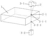
图1为内部缺陷检测方法示意图,1:待测试件,2:激光器,2-1:激光光斑,3-1:红外热像仪A,3-1-1:红外热像仪A测温点,3-2:红外热像仪B,3-2-1:红外热像仪B测温点;Figure 1 is a schematic diagram of the internal defect detection method, 1: the piece to be tested, 2: laser, 2-1: laser spot, 3-1: infrared thermal imaging camera A, 3-1-1: infrared thermal imaging camera A temperature measurement point , 3-2: thermal imaging camera B, 3-2-1: temperature measurement point of thermal imaging camera B;
图2为内部缺陷检测原理示意图,1:待测试件,4:第一次检测位置,5:第二次检测位置,6:第三次检测位置,7:内部缺陷;Figure 2 is a schematic diagram of the internal defect detection principle, 1: the piece to be tested, 4: the first detection position, 5: the second detection position, 6: the third detection position, 7: internal defects;
图3为无缺陷温度升高曲线示意图,T0为室温,Ta为红外热像仪A的温升曲线,Tb为红外热像仪B的温升曲线;Figure 3 is a schematic diagram of a defect-free temperature rise curve, T0 is room temperature, Ta is the temperature rise curve of the infrared thermal imager A, and Tb is the temperature rise curve of the infrared thermal imager B;
图4为有缺陷温度升高曲线示意图,T0为室温,Ta为红外热像仪A的温升曲线,Tb为红外热像仪B的温升曲线;Fig. 4 is a schematic diagram of a defective temperature rise curve, T0 is room temperature, Ta is the temperature rise curve of the infrared thermal imager A, and Tb is the temperature rise curve of the infrared thermal imager B;
图5为工件缺陷检测原理图,1:待测试件,7:内部缺陷,3-1-2:红外热像仪A检测异常高温点,3-2-2:红外热像仪B检测异常低温点。Figure 5 is the principle diagram of workpiece defect detection, 1: the workpiece to be tested, 7: internal defects, 3-1-2: infrared thermal imager A detects abnormally high temperature points, 3-2-2: infrared thermal imager B detects abnormally low temperature point.
具体实施方式Detailed ways
下面结合附图对本发明的技术方案进一步解释说明,但并不限定本发明的保护范围,凡是对本发明技术方案进行修改或者等同替换,而不脱离本发明技术方案的精神和范围,均应涵盖在本发明的保护范围中。The technical solution of the present invention will be further explained below in conjunction with the accompanying drawings, but the protection scope of the present invention is not limited. Any modification or equivalent replacement of the technical solution of the present invention without departing from the spirit and scope of the technical solution of the present invention shall be covered in In the protection scope of the present invention.
如图1所示,在待测试件1正面上方分别设置有一激光器2和红外热像仪A 3-1,在待测试件背面下方设有一红外热像仪B 3-2,将一束激光定功率照射在待测试件1正面上t1秒;红外热像仪A 3-1和红外热像仪B 3-2同时检测激光光斑2-1处上下方的温升曲线,检测最高值,根据最高值判断激光光斑处工件内部是否有缺陷。其中红外热像仪A 3-1的检测区(红外热像仪A测温点3-1-1)位于激光光斑2-1的正上方,红外热像仪B的检测区(红外热像仪B测温点3-2-1)位于激光光斑2-1的正下方,检测过程中红外热像仪A 3-1和红外热像仪B 3-2的检测区大小一致且保持不变。As shown in Figure 1, a
工件材质和表面粗糙度影响着对激光的吸收率,本检测方法关键需要令工件照射点温度快速升高几十度到一两百度,即一般照射时间(脉宽)最大不能超过2秒,脉宽在0.1-2秒之间。激光功率过小,照射时间过长,都会导致热量绕过缺陷传导至检测区,导致漏检。因此激光功率一般在几十瓦到几百瓦之间,主要根据工件的吸收率,如果工件吸收率较低,就需激光器大功率。在实际应用中,温度升高绝对值和升温速率都很重要,高的温度绝对值和升温速率,可获得较高的辩识度,相反过低的温度绝对值和升温速率,可能会出现漏检,误判。The material and surface roughness of the workpiece affect the absorption rate of the laser. The key to this detection method is to rapidly increase the temperature of the irradiation point of the workpiece by tens of degrees to one or two hundred degrees, that is, the general irradiation time (pulse width) cannot exceed 2 seconds at most, and the pulse The width is between 0.1-2 seconds. If the laser power is too small and the irradiation time is too long, the heat will bypass the defect and conduct to the detection area, resulting in missed detection. Therefore, the laser power is generally between tens of watts and hundreds of watts, mainly according to the absorption rate of the workpiece. If the absorption rate of the workpiece is low, a high power laser is required. In practical applications, both the absolute value of temperature rise and the rate of temperature rise are important. A high absolute value of temperature and rate of temperature increase can obtain a higher degree of discrimination. Check, misjudgment.
非金属的吸收率较高,一般都在0.6以上,例如光滑陶瓷为0.92,印刷电路板为0.94;而金属较低,铝抛光表面为0.04-0.06;不锈钢抛光表面为0.16。粗糙度也影响吸收率,同样表面粗化的铝为0.28,阳极化处理、浅灰、暗哑光的铝表面为0.97。The absorption rate of non-metals is relatively high, generally above 0.6, such as 0.92 for smooth ceramics, and 0.94 for printed circuit boards; while metals are relatively low, 0.04-0.06 for polished aluminum surfaces; 0.16 for polished stainless steel surfaces. Roughness also affects the absorption rate, which is 0.28 for aluminum with the same rough surface, and 0.97 for anodized, light gray, dark matte aluminum surface.
例如:同样欲使铝材表面在0.5秒内升温50度,抛光铝需500瓦,而粗化铝则需70瓦左右,阳极化处理、浅灰、暗哑光的铝表面只需20瓦左右。For example: if you want to heat up the aluminum surface by 50 degrees in 0.5 seconds, polished aluminum needs 500 watts, while rough aluminum needs about 70 watts, anodized, light gray, dark matte aluminum surface only needs about 20 watts .
在实际应用中,需将整块工件表面依据X-Y坐标划分为n个待测点阵,在待测点阵上按照上述方法进行逐点检测,依据扫描后得到的点阵温度分布图,即可绘制出工件正反面的检测图。两相比较就能知道工件内部缺陷的大小、形状及位置,其检测原理如图2所示。In practical applications, it is necessary to divide the entire workpiece surface into n lattices to be measured according to the X-Y coordinates, and perform point-by-point detection on the lattices to be measured according to the above method, and according to the lattice temperature distribution diagram obtained after scanning, you can Draw a detection map of the front and back of the workpiece. The size, shape and position of the internal defects of the workpiece can be known by comparing the two phases. The detection principle is shown in Figure 2.
当激光光斑处工件内部无缺陷时,其热传导良好,其温升正常,由于热量分别向四周及下方传导,因此红外热像仪B所测温度略小于红外热像仪A所测温度,如图3所示。当激光光斑下工件中存在缺陷时,由于热传导受阻,因此红外热像仪A所测温升最高值高于正常值,而红外热像仪B所测温度大大低于正常值,如图4所示。将检测过程中发现的异常高低温点记载下来,依据其位置信息和温差信息即可绘制出该工件的内部缺陷检测结果图,如图5所示。When there is no defect inside the workpiece at the laser spot, its heat conduction is good, and its temperature rise is normal. Since the heat is conducted to the surrounding and downward respectively, the temperature measured by infrared thermal imager B is slightly lower than that measured by infrared thermal imager A, as shown in the figure 3. When there is a defect in the workpiece under the laser spot, the highest temperature rise measured by thermal imaging camera A is higher than the normal value, while the temperature measured by thermal imaging camera B is much lower than the normal value, as shown in Figure 4. Show. The abnormal high and low temperature points found in the detection process are recorded, and the internal defect detection result map of the workpiece can be drawn according to its position information and temperature difference information, as shown in Figure 5.
Claims (5)
Priority Applications (1)
| Application Number | Priority Date | Filing Date | Title |
|---|---|---|---|
| CN201310293549XACN103383368A (en) | 2013-07-12 | 2013-07-12 | Method for dot-matrix thermal conduction temperature measurement detection of workpiece defect |
Applications Claiming Priority (1)
| Application Number | Priority Date | Filing Date | Title |
|---|---|---|---|
| CN201310293549XACN103383368A (en) | 2013-07-12 | 2013-07-12 | Method for dot-matrix thermal conduction temperature measurement detection of workpiece defect |
Publications (1)
| Publication Number | Publication Date |
|---|---|
| CN103383368Atrue CN103383368A (en) | 2013-11-06 |
Family
ID=49491215
Family Applications (1)
| Application Number | Title | Priority Date | Filing Date |
|---|---|---|---|
| CN201310293549XAPendingCN103383368A (en) | 2013-07-12 | 2013-07-12 | Method for dot-matrix thermal conduction temperature measurement detection of workpiece defect |
Country Status (1)
| Country | Link |
|---|---|
| CN (1) | CN103383368A (en) |
Cited By (3)
| Publication number | Priority date | Publication date | Assignee | Title |
|---|---|---|---|---|
| CN108918586A (en)* | 2016-10-26 | 2018-11-30 | 王琪 | Cable aging lateral position infrared detection method based on heating conduction detection |
| CN111537564A (en)* | 2020-06-16 | 2020-08-14 | 中北大学 | Metal microcrack depth detection system and method based on transmission type laser thermal imaging |
| PL443765A1 (en)* | 2020-04-10 | 2024-05-20 | University Of Limerick | A method and system for detecting/identifying and locating a hidden defect in a test object using three-dimensional infrared thermography |
Citations (7)
| Publication number | Priority date | Publication date | Assignee | Title |
|---|---|---|---|---|
| US5705821A (en)* | 1996-11-07 | 1998-01-06 | Sandia Corporation | Scanning fluorescent microthermal imaging apparatus and method |
| JPH11304740A (en)* | 1998-04-20 | 1999-11-05 | Matsushita Electric Ind Co Ltd | Conductive paste filling state inspection method |
| CN1292871A (en)* | 1998-02-10 | 2001-04-25 | 菲利普莫里斯生产公司 | Process control by transient thermography |
| JP2006250798A (en)* | 2005-03-11 | 2006-09-21 | Yokohama Rubber Co Ltd:The | Method and device for visual inspection of rubber hose |
| CN102183545A (en)* | 2011-01-31 | 2011-09-14 | 哈尔滨工业大学 | Infrared temperature measurement detection method for detecting solder joint reliability of circuit board |
| US20130120561A1 (en)* | 2011-11-14 | 2013-05-16 | Societe De Technologie Michelin | Infrared inspection of metallic web structures |
| CN103199030A (en)* | 2013-04-22 | 2013-07-10 | 哈尔滨工业大学 | Flip-chip welding spot defect detection method through temperature observation and measurement |
- 2013
- 2013-07-12CNCN201310293549XApatent/CN103383368A/enactivePending
Patent Citations (7)
| Publication number | Priority date | Publication date | Assignee | Title |
|---|---|---|---|---|
| US5705821A (en)* | 1996-11-07 | 1998-01-06 | Sandia Corporation | Scanning fluorescent microthermal imaging apparatus and method |
| CN1292871A (en)* | 1998-02-10 | 2001-04-25 | 菲利普莫里斯生产公司 | Process control by transient thermography |
| JPH11304740A (en)* | 1998-04-20 | 1999-11-05 | Matsushita Electric Ind Co Ltd | Conductive paste filling state inspection method |
| JP2006250798A (en)* | 2005-03-11 | 2006-09-21 | Yokohama Rubber Co Ltd:The | Method and device for visual inspection of rubber hose |
| CN102183545A (en)* | 2011-01-31 | 2011-09-14 | 哈尔滨工业大学 | Infrared temperature measurement detection method for detecting solder joint reliability of circuit board |
| US20130120561A1 (en)* | 2011-11-14 | 2013-05-16 | Societe De Technologie Michelin | Infrared inspection of metallic web structures |
| CN103199030A (en)* | 2013-04-22 | 2013-07-10 | 哈尔滨工业大学 | Flip-chip welding spot defect detection method through temperature observation and measurement |
Cited By (3)
| Publication number | Priority date | Publication date | Assignee | Title |
|---|---|---|---|---|
| CN108918586A (en)* | 2016-10-26 | 2018-11-30 | 王琪 | Cable aging lateral position infrared detection method based on heating conduction detection |
| PL443765A1 (en)* | 2020-04-10 | 2024-05-20 | University Of Limerick | A method and system for detecting/identifying and locating a hidden defect in a test object using three-dimensional infrared thermography |
| CN111537564A (en)* | 2020-06-16 | 2020-08-14 | 中北大学 | Metal microcrack depth detection system and method based on transmission type laser thermal imaging |
Similar Documents
| Publication | Publication Date | Title |
|---|---|---|
| CN103383358A (en) | Dot-matrix type heat conduction temperature measurement nondestructive crack detection method | |
| CN103926274B (en) | Infrared thermal wave radar imaging nondestructive testing method for defects of carbon fiber reinforced plastic (CFRP) plywood | |
| JP6301951B2 (en) | Sample inspection method and system using thermography | |
| Burrows et al. | Thermographic detection of surface breaking defects using a scanning laser source | |
| Tashan et al. | Detection of cracks in concrete strengthened with CFRP systems using infra-red thermography | |
| CN107340328A (en) | A kind of weldment defect detecting system and detection method | |
| CN107081503A (en) | The infrared nondestructive detection device and its Infrared Non-destructive Testing method of a kind of arc-welding quality | |
| CN103698393A (en) | Magneto-optical imaging nondestructive detection method of weld defects | |
| Rodríguez-Martin et al. | Cooling analysis of welded materials for crack detection using infrared thermography | |
| CN203216857U (en) | Infrared detection device for metal defects | |
| CN102735687B (en) | An Infrared Sequential Heatmap Analysis Method for Impact Defects in Carbon Fiber Composite Materials | |
| US20160144452A1 (en) | System and method for detecting a defect in a workpiece undergoing material processing by an energy point source | |
| CN106404835A (en) | Infrared coherent thermal wave imaging system and detection method based on system | |
| CN105241923A (en) | Flip-chip bonding welded spot defect detection method | |
| CN109613063A (en) | A device and method for detecting thermal barrier coating surface based on area array pulsed laser excitation | |
| CN115015323B (en) | Eddy current infrared surface conformal non-obstructed sensor with complex structure and defect evaluation method | |
| CN107132271A (en) | Structure light and magneto-optic imaging double-sensing appearance of weld and defect lossless detection method | |
| JP5831940B2 (en) | Nondestructive inspection method and nondestructive inspection device for delamination in coating layer | |
| CN204495772U (en) | Face of weld and sub-surperficial tiny flaw magneto-optic imaging non-destructive pick-up unit | |
| CN103383367A (en) | Method for scanning type thermal conduction line temperature detection of workpiece shallow cracks | |
| CN105067663A (en) | Device and method for detecting thermal sealing of aerostat envelope material | |
| CN108037091A (en) | Composites gas cylinder fatigue damage infrared detection system | |
| CN206764093U (en) | A kind of infrared nondestructive detection device of arc-welding quality | |
| CN103383368A (en) | Method for dot-matrix thermal conduction temperature measurement detection of workpiece defect | |
| Broberg et al. | Comparison of NDT–methods for automatic inspection of weld defects |
Legal Events
| Date | Code | Title | Description |
|---|---|---|---|
| C06 | Publication | ||
| PB01 | Publication | ||
| C10 | Entry into substantive examination | ||
| SE01 | Entry into force of request for substantive examination | ||
| C02 | Deemed withdrawal of patent application after publication (patent law 2001) | ||
| WD01 | Invention patent application deemed withdrawn after publication | Application publication date:20131106 |