CN103376076A - Three-dimensional probe compensation and space error measuring system and method - Google Patents
Three-dimensional probe compensation and space error measuring system and methodDownload PDFInfo
- Publication number
- CN103376076A CN103376076ACN2012101197198ACN201210119719ACN103376076ACN 103376076 ACN103376076 ACN 103376076ACN 2012101197198 ACN2012101197198 ACN 2012101197198ACN 201210119719 ACN201210119719 ACN 201210119719ACN 103376076 ACN103376076 ACN 103376076A
- Authority
- CN
- China
- Prior art keywords
- stylus
- compensation
- sphere
- point
- standard
- Prior art date
- Legal status (The legal status is an assumption and is not a legal conclusion. Google has not performed a legal analysis and makes no representation as to the accuracy of the status listed.)
- Pending
Links
Images


Classifications
- G—PHYSICS
- G01—MEASURING; TESTING
- G01B—MEASURING LENGTH, THICKNESS OR SIMILAR LINEAR DIMENSIONS; MEASURING ANGLES; MEASURING AREAS; MEASURING IRREGULARITIES OF SURFACES OR CONTOURS
- G01B21/00—Measuring arrangements or details thereof, where the measuring technique is not covered by the other groups of this subclass, unspecified or not relevant
- G01B21/02—Measuring arrangements or details thereof, where the measuring technique is not covered by the other groups of this subclass, unspecified or not relevant for measuring length, width, or thickness
- G01B21/04—Measuring arrangements or details thereof, where the measuring technique is not covered by the other groups of this subclass, unspecified or not relevant for measuring length, width, or thickness by measuring coordinates of points
- G01B21/045—Correction of measurements
Landscapes
- Physics & Mathematics (AREA)
- General Physics & Mathematics (AREA)
- A Measuring Device Byusing Mechanical Method (AREA)
- Length Measuring Devices With Unspecified Measuring Means (AREA)
Abstract
Translated fromChinese
Description
Translated fromChinese技术领域technical field
本发明涉及一种三次元量测系统及方法,尤其涉及一种三次元测针补偿及空间误差测定系统及方法。The invention relates to a three-dimensional measurement system and method, in particular to a three-dimensional probe compensation and space error measurement system and method.
背景技术Background technique
三次元机台的硬件精度主要包含:测针系统的精度、光学尺的精度、机器本体架构(Frame)的精度。其中,测针系统(包含旋转部件、感应部件、测杆、测头等)的精度最为重要,其直接关系到量测点的精度。然而,在制造与日益使用过程中,测针系统会因为磨损造成精度的丢失,因此,需要对测针系统的精度进行补偿。The hardware accuracy of the three-dimensional machine mainly includes: the accuracy of the stylus system, the accuracy of the optical ruler, and the accuracy of the machine body frame (Frame). Among them, the accuracy of the stylus system (including rotating parts, sensing parts, measuring rods, probes, etc.) is the most important, which is directly related to the accuracy of the measuring point. However, in the process of manufacture and increasing use, the accuracy of the stylus system will be lost due to wear, so the accuracy of the stylus system needs to be compensated.
发明内容Contents of the invention
鉴于以上内容,有必要提供一种三次元测针补偿及空间误差测定系统,其通过对一个标准球的分层取点与计算,来避开量测时容易撞针的部位,并通过两次量测来提高测针的补偿精度和效率。In view of the above, it is necessary to provide a three-dimensional stylus compensation and spatial error measurement system, which avoids the parts that are easy to hit the needle during measurement by taking points and calculating layers of a standard sphere, and through two measurements measurement to improve the compensation accuracy and efficiency of the stylus.
还有必要提供一种三次元测针补偿及空间误差测定方法,其通过对一个标准球的分层取点与计算,来避开量测时容易撞针的部位,并通过两次量测来提高测针的补偿精度和效率。It is also necessary to provide a three-dimensional stylus compensation and space error measurement method, which avoids the parts that are easy to hit the needle during measurement by layering points and calculations on a standard sphere, and improves the accuracy by two measurements. Stylus compensation accuracy and efficiency.
一种三次元测针补偿及空间误差测定系统,运行于电子装置中,所述测针包括测头及与三次元机台连接的测杆。该系统包括:导入模块用于提供一个带有支撑杆的标准球,导入该标准球的半径R1、该支撑杆的半径R2、该标准球顶部任意点的坐标PT及测杆的法向N1;表面点计算模块用于按照比例将该标准球分成多层,并根据该标准球的半径R1、所述顶部任意点的坐标PT及在所述标准球上点取的表面点的个数Num,计算出所述点取的各表面点的坐标及向量,得到坐标集PTS;旋转模块用于将所述测杆的法向N1、标准球的法向N2进行差乘得到旋转法向N3,将所述标准球绕该旋转法向N3旋转一个预设角度得到旋转矩阵mat;表面点更新模块用于将该旋转矩阵mat与所述各表面点的坐标相乘,计算得到所述各表面点的新坐标,并利用各表面点的新坐标更新所述坐标集PTS;实际量测模块用于根据上述坐标集PTS生成量测程序,将该量测程序传送给三次元机台以控制所述测针实际量测工件两次,分别得到实际量测的点集Refs和Meas;及补偿与误差测定模块用于根据实际量测的点集Refs和Meas、标准球的半径R1及测头的半径R3计算该测针的补偿值,利用该补偿值补偿该测针,并根据实际量测的点集Refs和Meas计算该测针的空间误差。A three-dimensional stylus compensation and space error measurement system runs in an electronic device, and the stylus includes a measuring head and a measuring rod connected with a three-dimensional machine. The system includes: an import module for providing a standard sphere with a support rod, importing the radius R1 of the standard sphere, the radius R2 of the support rod, the coordinate PT of any point on the top of the standard sphere and the normal direction N1 of the measuring rod; The surface point calculation module is used to divide the standard sphere into multiple layers in proportion, and according to the radius R1 of the standard sphere, the coordinate PT of any point on the top and the number Num of surface points taken on the standard sphere, Calculate the coordinates and vectors of each surface point taken by the point to obtain the coordinate set PTS; the rotation module is used to perform differential multiplication of the normal direction N1 of the measuring rod and the normal direction N2 of the standard sphere to obtain the rotation normal direction N3, and The standard sphere is rotated by a preset angle around the rotation method to N3 to obtain a rotation matrix mat; the surface point update module is used to multiply the rotation matrix mat by the coordinates of each surface point, and calculate the coordinates of each surface point new coordinates, and use the new coordinates of each surface point to update the coordinate set PTS; the actual measurement module is used to generate a measurement program according to the above coordinate set PTS, and transmit the measurement program to the three-dimensional machine to control the measurement The workpiece is actually measured twice to obtain the actual measured point sets Refs and Meas respectively; and the compensation and error measurement module is used to base the actual measured point set Refs and Meas, the radius R1 of the standard sphere and the radius R3 of the probe Calculate the compensation value of the stylus, use the compensation value to compensate the stylus, and calculate the spatial error of the stylus according to the actually measured point set Refs and Meas.
一种三次元测针补偿及空间误差测定方法,应用于电子装置中,其中,所述测针包括测头及与三次元量测机台连接的测杆,该方法包括:提供一个带有支撑杆的标准球,导入该标准球的半径R1、该支撑杆的半径R2、该标准球顶部任意点的坐标PT及测杆的法向N1;按照比例将该标准球分成多层,并根据该标准球的半径R1、所述顶部任意点的坐标PT及在所述标准球上点取的表面点的个数Num,计算出所述点取的各表面点的坐标及向量,得到坐标集PTS;将所述测杆的法向N1、标准球的法向N2进行差乘得到旋转法向N3,将所述标准球绕该旋转法向N3旋转一个预设角度得到旋转矩阵mat;将该旋转矩阵mat与所述各表面点的坐标相乘,计算得到所述各表面点的新坐标,并利用各表面点的新坐标更新所述坐标集PTS;根据上述坐标集PTS生成量测程序,将该量测程序传送给三次元机台以控制所述测针实际量测工件两次,分别得到实际量测的点集Refs和Meas;及根据实际量测的点集Refs和Meas、标准球的半径R1及测头的半径R3计算该测针的补偿值,利用该补偿值补偿该测针,并根据实际量测的点集Refs和Meas计算该测针的空间误差。A three-dimensional stylus compensation and space error measurement method applied to electronic devices, wherein the stylus includes a stylus head and a measuring rod connected to a three-dimensional measuring machine, the method includes: providing a support The standard sphere of the rod, import the radius R1 of the standard sphere, the radius R2 of the support rod, the coordinate PT of any point on the top of the standard sphere and the normal direction N1 of the measuring rod; the standard sphere is divided into multiple layers according to the proportion, and according to the The radius R1 of the standard sphere, the coordinate PT of any point on the top and the number Num of the surface points taken on the standard sphere, calculate the coordinates and vectors of each surface point taken by the point, and obtain the coordinate set PTS ; The normal direction N1 of the measuring rod and the normal direction N2 of the standard ball are differentially multiplied to obtain the rotation normal direction N3, and the standard ball is rotated around the rotation normal direction N3 by a preset angle to obtain the rotation matrix mat; the rotation The matrix mat is multiplied by the coordinates of each surface point to calculate the new coordinates of each surface point, and use the new coordinates of each surface point to update the coordinate set PTS; generate a measurement program according to the above coordinate set PTS, and The measurement program is sent to the three-dimensional machine to control the stylus to actually measure the workpiece twice to obtain the actual measured point set Refs and Meas respectively; and according to the actual measured point set Refs and Meas, the standard ball The radius R1 and the radius R3 of the stylus calculate the compensation value of the stylus, use the compensation value to compensate the stylus, and calculate the spatial error of the stylus according to the actual measured point set Refs and Meas.
相较于现有技术,所述的三次元测针补偿及空间误差测定系统及方法,通过对高精度陶瓷标准球的分层取点及按照算法的自定比例取点,使测头各部位区域基本能接触到,能反应测头真实使用情况。Compared with the prior art, the three-dimensional stylus compensation and spatial error measurement system and method, through layered points of high-precision ceramic standard balls and self-proportioned points according to the algorithm, make each part of the probe The area is basically accessible and can reflect the actual use of the probe.
附图说明Description of drawings
图1是本发明较佳实施例中的三次元测针补偿及空间误差测定系统的运行环境示意图。Fig. 1 is a schematic diagram of the operating environment of the three-dimensional stylus compensation and spatial error measurement system in a preferred embodiment of the present invention.
图2是图1中电子装置的结构示意图。FIG. 2 is a schematic structural diagram of the electronic device in FIG. 1 .
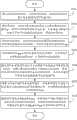
图3是本发明较佳实施例中的三次元测针补偿及空间误差测定方法的作业流程图。Fig. 3 is a flow chart of the three-dimensional stylus compensation and spatial error measurement method in the preferred embodiment of the present invention.
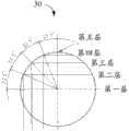
图4是图3步骤S202中按照比例将标准球划分为五层的示意图。FIG. 4 is a schematic diagram of dividing the standard sphere into five layers in proportion in step S202 in FIG. 3 .
图5是图3步骤S202中计算每个表面点的坐标的示意图。FIG. 5 is a schematic diagram of calculating the coordinates of each surface point in step S202 in FIG. 3 .
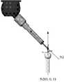
图6是图3步骤S204中计算旋转法向N3的示意图。FIG. 6 is a schematic diagram of calculating the rotation normal direction N3 in step S204 of FIG. 3 .
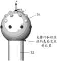
图7和图8是图3步骤S208中重新计算标准球的表面点的坐标的示意图。7 and 8 are schematic diagrams of recalculating the coordinates of the surface points of the standard sphere in step S208 of FIG. 3 .
主要元件符号说明Description of main component symbols
如下具体实施方式将结合上述附图进一步说明本发明。The following specific embodiments will further illustrate the present invention in conjunction with the above-mentioned drawings.
具体实施方式Detailed ways
如图1所示,是本发明较佳实施例中的三次元测针补偿及空间误差测定系统的运行环境示意图。该三次元测针补偿及空间误差测定系统10(以下简称为“系统10”)运行于一台电子装置1中,该电子装置1用于控制一个三次元机台(图中未示出)的测针2量测工件。其中,测针2包括测头20、测杆22、转部件(图中未示出)和感应部件(图中未示出)。As shown in FIG. 1 , it is a schematic diagram of the operating environment of the three-dimensional stylus compensation and spatial error measurement system in a preferred embodiment of the present invention. The three-dimensional stylus compensation and spatial error measurement system 10 (hereinafter referred to as "
为了减少测针2量测工件时的撞针,本实施例通过对一个带有支撑杆32的标准球30进行分层取点与计算,来生成量测程序。系统10利用该量测程序控制测针2两次实际量测工件,并根据量测的数据对所述测针2进行补偿及测定该测针2所在的空间误差。如图8所示,所述标准球30与支撑杆32相连。另外,通过对所述标准球30的分层取点与计算,还可以避开量测时容易撞针的部位,及通过所述两次量测可以提高测针2的补偿精度和效率。In order to reduce the striker when the
在本实施例中,所述标准球30是一个由高精度陶瓷支撑的球体,该标准球30的半径比测头20的半径大,且比支撑杆32的半径大。In this embodiment, the
如图2所示,是图1中电子装置1的结构示意图。在该示意图中,电子装置1除了包括所述系统10外,还包括存储设备12和至少一个处理器14。在本实施例中,所述系统10以软件程序或指令的形式安装在该存储设备12中,并由处理器14执行。该系统10包括导入模块100、表面点计算模块102、旋转模块104、表面点更新模块106、实际量测模块108及补偿与误差测定模块110。本发明所称的模块是完成一特定功能的计算机程序段,比程序更适合于描述软件在计算机中的执行过程,因此在本发明以下对软件描述都以模块描述。As shown in FIG. 2 , it is a schematic structural diagram of the electronic device 1 in FIG. 1 . In this schematic diagram, the electronic device 1 includes a storage device 12 and at least one processor 14 in addition to the
所述导入模块100用于从存储设备12中导入所述标准球的半径R1、支撑杆的半径R2、该标准球30顶部任意点的坐标PT及所述测杆22的法向N1。The import module 100 is used to import the radius R1 of the standard sphere, the radius R2 of the support rod, the coordinate PT of any point on the top of the
所述表面点计算模块102用于按照比例将该标准球30分成多层,并根据该标准球30的半径R1、所述顶部任意点的坐标PT及在所述标准球30上点取的表面点(即在标准球30上取点)的个数Num,计算出所述点取的各表面点的坐标及向量,得到坐标集PTS。本实施例中,在所述标准球30上取点的个数Num可预先设定,标准取点个数为二十五个或二十五个以上。The surface point calculation module 102 is used to divide the
例如,表面点计算模块102根据标准球30的半径R1、所述顶部任意点的坐标PT及在所述标准球30上取点的个数为Num,按照比例把该标准球30分成多层。由于量测时,标准球30的下半部分不会与工件接触,因此,本实施例将该标准球30的上半部分进行等比例划分,如图4所示,以22.5度的夹角将该标准球30的上半部分进行等比例划分后共得到五层,每层上的表面点的个数可以由公式大致计算得出。如第一层的表面点个数=(Num-1)*33.3%,第二层的表面点个数=(Num-1)*16.7%,第三层的表面点个数=(Num-1)*33.3%,第四层的表面点个数=(Num-1)*16.7%,第五层的表面点个数=1。其中,第一层即所述标准球30的球心所在的层,第五层即所述标准球30顶点所在的层。For example, the surface point calculation module 102 divides the
其中,该标准球30的球心坐标ptCenter=PT-R1。具体地,该球心坐标中的x值ptCenter.x等于所述顶部任意点的坐标PT在x轴上的值,该球心坐标中的y值ptCenter.y等于所述坐标PT在y轴上的值,及该球心坐标中的z值ptCenter.z等于所述坐标PT在z轴上的值与标准球30的半径R1间的差值。Wherein, the coordinates of the center of the
而每层的圆心坐标pt=ptStepCenter+sin(22.5)*R1。具体地,圆心坐标中的x值ptStepCenter.x=ptCenter.x,圆心坐标中的y值ptStepCenter.y=ptCenter.y,圆心坐标中的z值ptStepCenter.z=ptCenter.z+sin(22.5°)*R1。The center coordinates of each layer are pt=ptStepCenter+sin(22.5)*R1. Specifically, the x value in the center coordinates ptStepCenter.x=ptCenter.x, the y value in the center coordinates ptStepCenter.y=ptCenter.y, the z value in the center coordinates ptStepCenter.z=ptCenter.z+sin(22.5°) *R1.
如图5所示,假设每层上每两个表面点间的夹角为a,则a=360/每层表面点的个数,其中,第一个表面点(简称“第一点”)的坐标=ptStepCenter.x+R1,第n点的坐标=第一点绕轴(0,0,1)旋转角度(a*n)后的坐标,所述表面点计算模块102由每个表面点的坐标指向标准球30的球心得到每个表面点的向量。所述表面点计算模块102由上述计算出的各表面点的坐标及向量得到所述坐标集PTS。As shown in Figure 5, assuming that the angle between every two surface points on each layer is a, then a=360/the number of surface points on each layer, where the first surface point (referred to as "the first point") Coordinates=ptStepCenter.x+R1, coordinates of the nth point=the coordinates of the first point after the rotation angle (a*n) around the axis (0,0,1), the surface point calculation module 102 consists of each surface point The coordinates point to the center of the
所述旋转模块104用于将如图6所示的测杆22的法向N1、标准球30的法向N2进行差乘得到旋转法向N3,将所述标准球30绕该旋转法向N3旋转一个预设角度得到旋转矩阵mat。其中,该预设角度等于所述测杆22的法向N1与标准球30的法向N2间的夹角。The rotation module 104 is used to perform differential multiplication between the normal N1 of the
所述表面点更新模块106用于将该旋转矩阵mat与所述各表面点的坐标相乘,计算得到所述各表面点的新坐标,并利用各表面点的新坐标更新所述坐标集PTS。The surface point update module 106 is used for multiplying the rotation matrix mat by the coordinates of each surface point to calculate the new coordinates of each surface point, and update the coordinate set PTS with the new coordinates of each surface point .
为了提高补偿精度,本实施例需要避开量测时容易撞针的部位,因此,需要对所述各表面点的新坐标进行再次更新。具体而言,所述表面点更新模块106将所述支撑杆32和标准球30的交点的坐标与上述每层中各表面点的新坐标进行比较。当某个新坐标的Z值小于所述交点的Z值时,重新计算该新坐标所在层上各表面点的坐标值,并利用该重新计算出的坐标值更新所述坐标集PTS。经过旋转后的表面点的坐标可能会比支撑杆32和标准球30的球面的交点的位置还小,因此要避开如图7所示的该支撑杆32和标准球30的所有交点,通过下述公式重新计算所述各表面点的坐标:第n点坐标=第一点绕轴(0,0,1)旋转角度((360-a1)*n)后的坐标。所述表面点更新模块106利用该重新计算出的坐标更新所述坐标集PTS。In order to improve the compensation accuracy, this embodiment needs to avoid the parts that are easy to strike the needle during measurement, so the new coordinates of the above-mentioned surface points need to be updated again. Specifically, the surface point update module 106 compares the coordinates of the intersection of the
所述实际量测模块108用于根据上述更新后的坐标集PTS生成量测程序,并将该量测程序传送给三次元机台,以控制所述测针2实际量测工件。本实施例中,为了提高补偿精度,会控制测针2实际量测工件两次,并由此得到实际量测点集Refs和Meas。The actual measurement module 108 is used to generate a measurement program according to the above-mentioned updated coordinate set PTS, and transmit the measurement program to the three-dimensional machine, so as to control the
本实施例中,所述量测程序为I++量测程序。I++是三次元业界中的通用格式,适合大部分量测机台。例如,所述量测程序中各表面点的坐标与向量格式为:In this embodiment, the measurement program is an I++ measurement program. I++ is a common format in the 3D industry and is suitable for most measuring machines. For example, the coordinates and vector format of each surface point in the measurement program are:
C0001 PtMeas(IJK(-0.00000, -0.00000, 1.00000), X(0.00000), Y(0.00000), Z(0.00000))C0001 PtMeas(IJK(-0.00000, -0.00000, 1.00000), X(0.00000), Y(0.00000), Z(0.00000))
C0002C0002
PtMeas(X(9.23879533),Y(-3.82683432),Z(-12.00000000),IJK(0.92387953, -0.38268343, 0.00000000))PtMeas(X(9.23879533),Y(-3.82683432),Z(-12.00000000),IJK(0.92387953, -0.38268343, 0.00000000))
C0003C0003
PtMeas(X(3.82683432),Y(-9.23879533),Z(-12.00000000),IJK(0.38268343, -0.92387953, 0.00000000))。PtMeas(X(3.82683432),Y(-9.23879533),Z(-12.00000000),IJK(0.38268343,-0.92387953,0.00000000)).
所述补偿与误差测定模块110用于根据实际量测的点集Refs和Meas、标准球的半径R1及测头20的半径R3计算出该测针2的补偿值,利用该补偿值补偿该测针2,并根据实际量测点集Refs和Meas计算测针2的空间误差。本实施例中,所述补偿值包括测头20的半径补偿值和球心补偿值。The compensation and error measurement module 110 is used to calculate the compensation value of the
具体地,所述补偿与误差测定模块110根据上述实际量测的点集Refs拟合第一参考球,得到球心ptRef及该第一参考球的半径rRef;根据所述实际量测点集Meas拟合第二参考球,得到球心ptMeas及该第二参考球的半径rMeas;根据所述测杆22的出厂标准长度得到所述标准球的球心坐标ptMorminal,该标准球的球心坐标ptMorminal等于(0,0,–标准长度);利用公式计算出所述测头20的半径补偿值,该半径补偿值rOffset=rMeas–R1+stdProbeR,其中,stdProbeR为所述测头20的出厂标准半径;及利用公式计算出所述测头20的球心补偿值,该球心补偿值ptOffset=ptMeas+ptNorminal–ptRef。Specifically, the compensation and error measurement module 110 fits the first reference sphere according to the above-mentioned actual measured point set Refs to obtain the center ptRef and the radius rRef of the first reference sphere; according to the actual measured point set Meas Fit the second reference sphere to obtain the center of the sphere ptMeas and the radius rMeas of the second reference sphere; obtain the center coordinate ptMorminal of the standard sphere according to the factory standard length of the measuring
另外,所述补偿与误差测定模块110利用公式计算出所述测针2的空间误差,该测针2的空间误差等于maxR–minR,其中,maxR为所述实际量测点集Meas中的表面点与所述第二参考球的球心间的最大距离,minR为所述实际量测点集Meas中的表面点与所述第二参考球的球心间的最小距离。In addition, the compensation and error measurement module 110 uses a formula to calculate the spatial error of the
如图3所示,是本发明较佳实施例中的三次元测针补偿及空间误差测定方法的作业流程图。As shown in FIG. 3 , it is a flow chart of the three-dimensional stylus compensation and spatial error measurement method in the preferred embodiment of the present invention.
步骤S300,提供一个带有支撑杆32的标准球30,导入模块100从存储设备12中导入所述标准球的半径R1、支撑杆的半径R2、该标准球30顶部任意点的坐标PT及所述测杆22的法向N1。Step S300, providing a
步骤S302,表面点计算模块102按照比例将该标准球30分成多层,并根据该标准球30的半径R1、所述顶部任意点的坐标PT及在所述标准球30上点取的表面点(即在标准球30上取点)的个数Num,计算出所述点取的各表面点的坐标及向量,得到坐标集PTS。Step S302, the surface point calculation module 102 divides the
本实施例中,在所述标准球30上点取的表面点的个数Num一般为二十五个以上,所述标准球30可以被划分成五层。第一层为所述标准球30的球心所在的层,第五层为所述标准球30顶点所在的层。每层上的表面点的个数可以由公式大致计算得出。如第一层的表面点个数=(Num-1)*33.3%,第二层的表面点个数=(Num-1)*16.7%,第三层的表面点个数=(Num-1)*33.3%,第四层的表面点个数=(Num-1)*16.7%,第五层的表面点个数=1。所述各表面点的坐标与向量计算方法可如图2、图4至图5中的描述。In this embodiment, the number Num of surface points taken on the
步骤S304,旋转模块104将测杆22的法向N1、标准球30的法向N2进行差乘得到旋转法向N3(如图6所示),将所述标准球30绕该旋转法向N3旋转一个预设角度得到旋转矩阵mat。其中,该预设角度等于所述测杆22的法向N1与标准球30的法向N2间的夹角。Step S304, the rotation module 104 performs differential multiplication between the normal direction N1 of the measuring
步骤S306,所述表面点更新模块106将该旋转矩阵mat与所述各表面点的坐标相乘,计算得到所述各表面点的新坐标,并利用各表面点的新坐标更新所述坐标集PTS。Step S306, the surface point updating module 106 multiplies the rotation matrix mat by the coordinates of each surface point, calculates the new coordinates of each surface point, and updates the coordinate set using the new coordinates of each surface point PTS.
步骤S308,所述表面点更新模块106将所述支撑杆32和标准球30的交点的坐标与上述每层中各表面点的新坐标进行比较,当某个新坐标的Z值小于所述交点的Z值时,利用公式重新计算该新坐标所在层上各表面点的坐标值,并利用该重新计算出的坐标值更新所述坐标集PTS。在本实施例中,所述公式为:第n点坐标=第一点绕轴(0,0,1)旋转角度((360-a1)*n)后的坐标。Step S308, the surface point update module 106 compares the coordinates of the intersection of the
步骤S310,实际量测模块108根据上述更新后的坐标集PTS生成量测程序,并将该量测程序传送给三次元机台,以控制所述测针2实际量测工件。本实施例中,为了提高补偿精度,会控制测针2实际量测工件两次,并由此得到实际量测点集Refs和Meas。Step S310 , the actual measurement module 108 generates a measurement program according to the above-mentioned updated coordinate set PTS, and transmits the measurement program to the three-dimensional machine to control the
步骤S312,补偿与误差测定模块110根据实际量测的点集Refs和Meas、标准球的半径R1及测头20的半径R3计算出该测针2的补偿值,利用该补偿值补偿该测针2,并根据实际量测点集Refs和Meas计算测针2的空间误差。本实施例中,所述补偿值包括测头20的半径补偿值和球心补偿值。Step S312, the compensation and error measurement module 110 calculates the compensation value of the
具体地,所述补偿与误差测定模块110根据上述实际量测的点集Refs拟合第一参考球,得到球心ptRef及该第一参考球的半径rRef;根据所述实际量测点集Meas拟合第二参考球,得到球心ptMeas及该第二参考球的半径rMeas;根据所述测杆22的出厂标准长度得到所述标准球的球心坐标ptMorminal,该标准球的球心坐标ptMorminal等于(0,0,–标准长度);利用公式计算出所述测头20的半径补偿值,该半径补偿值rOffset=rMeas–R1+stdProbeR,其中,stdProbeR为所述测头20的出厂标准半径;及利用公式计算出所述测头20的球心补偿值,该球心补偿值ptOffset=ptMeas+ptNorminal–ptRef。所述补偿与误差测定模块110利用公式计算出所述测针2的空间误差,该测针2的空间误差等于maxR–minR,其中,maxR为所述实际量测点集Meas中的表面点与所述第二参考球的球心间的最大距离,minR为所述实际量测点集Meas中的表面点与所述第二参考球的球心间的最小距离。Specifically, the compensation and error measurement module 110 fits the first reference sphere according to the above-mentioned actual measured point set Refs to obtain the center ptRef and the radius rRef of the first reference sphere; according to the actual measured point set Meas Fit the second reference sphere to obtain the center of the sphere ptMeas and the radius rMeas of the second reference sphere; obtain the center coordinate ptMorminal of the standard sphere according to the factory standard length of the measuring
最后应说明的是,以上实施例仅用以说明本发明的技术方案而非限制,尽管参照较佳实施例对本发明进行了详细说明,本领域的普通技术人员应当理解,可以对本发明的技术方案进行修改或等同替换,而不脱离本发明技术方案的精神和范围。例如,将此方法应用于在清晰的边界线上寻找边界点。Finally, it should be noted that the above embodiments are only used to illustrate the technical solutions of the present invention without limitation. Although the present invention has been described in detail with reference to the preferred embodiments, those of ordinary skill in the art should understand that the technical solutions of the present invention can be Modifications or equivalent replacements can be made without departing from the spirit and scope of the technical solutions of the present invention. For example, apply this method to finding boundary points on sharp boundary lines.
Claims (10)
Translated fromChinesePriority Applications (3)
| Application Number | Priority Date | Filing Date | Title |
|---|---|---|---|
| CN2012101197198ACN103376076A (en) | 2012-04-23 | 2012-04-23 | Three-dimensional probe compensation and space error measuring system and method |
| TW101114833ATWI510760B (en) | 2012-04-23 | 2012-04-26 | System and method for compensating probe of 3d coordinate measurement machine and measuring space error of the probe |
| US13/862,615US20130282329A1 (en) | 2012-04-23 | 2013-04-15 | Computing device and method of compensating precision of measurements using probes of three-dimensional measurement machines |
Applications Claiming Priority (1)
| Application Number | Priority Date | Filing Date | Title |
|---|---|---|---|
| CN2012101197198ACN103376076A (en) | 2012-04-23 | 2012-04-23 | Three-dimensional probe compensation and space error measuring system and method |
Publications (1)
| Publication Number | Publication Date |
|---|---|
| CN103376076Atrue CN103376076A (en) | 2013-10-30 |
Family
ID=49380909
Family Applications (1)
| Application Number | Title | Priority Date | Filing Date |
|---|---|---|---|
| CN2012101197198APendingCN103376076A (en) | 2012-04-23 | 2012-04-23 | Three-dimensional probe compensation and space error measuring system and method |
Country Status (3)
| Country | Link |
|---|---|
| US (1) | US20130282329A1 (en) |
| CN (1) | CN103376076A (en) |
| TW (1) | TWI510760B (en) |
Cited By (3)
| Publication number | Priority date | Publication date | Assignee | Title |
|---|---|---|---|---|
| CN105806184A (en)* | 2016-05-06 | 2016-07-27 | 深圳市铭利达精密机械有限公司 | Method for measuring internal diameter of hole |
| CN107957256A (en)* | 2018-01-09 | 2018-04-24 | 上海兰宝传感科技股份有限公司 | The automatic compensation detecting device of sensor and method |
| CN114397698A (en)* | 2021-12-09 | 2022-04-26 | 中煤科工集团西安研究院有限公司 | Double-coordinate system precision unifying method and system suitable for seismic physical simulation |
Families Citing this family (3)
| Publication number | Priority date | Publication date | Assignee | Title |
|---|---|---|---|---|
| CN103659467B (en)* | 2013-11-15 | 2016-02-24 | 西安理工大学 | The scaling method of the axial pretravel of touch trigger probe |
| CN105423950A (en)* | 2015-12-18 | 2016-03-23 | 昆山艾尔发计量科技有限公司 | Precision detection ball bar for 3D scanner and articulated arm type coordinate measuring machine |
| CN105606026B (en)* | 2016-02-16 | 2018-12-07 | 广东工业大学 | A kind of sphere centre coordinate measuring device and its measurement method |
Citations (10)
| Publication number | Priority date | Publication date | Assignee | Title |
|---|---|---|---|---|
| CN1055812A (en)* | 1991-02-01 | 1991-10-30 | 天津大学 | The one dimension spherical column mensuration of 21 mechanism errors of three coordinate measuring machine and the self checking method of measurement mechanism and device |
| JPH07260471A (en)* | 1994-03-16 | 1995-10-13 | Nikon Corp | Surface shape measuring device |
| JP2000046543A (en)* | 1998-07-29 | 2000-02-18 | Canon Inc | 3D shape measuring device |
| US20010025427A1 (en)* | 2000-02-15 | 2001-10-04 | Werner Lotze | Articulated device for the probe head of a coordinate measuring apparatus |
| CN1731232A (en)* | 2005-09-05 | 2006-02-08 | 长春理工大学 | A quasi-universal compensating mirror for optical aspheric surface detection |
| CN1995943A (en)* | 2007-01-04 | 2007-07-11 | 四川大学 | Omnibearing detection method for large-diameter aspherical mirror |
| CN101278867A (en)* | 2007-12-28 | 2008-10-08 | 中国科学院光电技术研究所 | A reflective artificial lens aberration Hartmann measuring instrument |
| CN101382409A (en)* | 2008-10-24 | 2009-03-11 | 红塔烟草(集团)有限责任公司 | Method for precisely measuring points on space curved surface and space curved surface by using barycentric coordinate |
| CN101403611A (en)* | 2008-11-14 | 2009-04-08 | 红塔烟草(集团)有限责任公司 | Method for measuring space rotating curved surface with microdelta barycentric coordinates as objective point |
| CN101424506A (en)* | 2008-10-17 | 2009-05-06 | 红塔烟草(集团)有限责任公司 | Method for precisely measuring points on space curved surface and space curved surface by using coordinate of sphere center of measuring needle |
Family Cites Families (4)
| Publication number | Priority date | Publication date | Assignee | Title |
|---|---|---|---|---|
| EP2008120B1 (en)* | 2006-04-20 | 2010-12-08 | Faro Technologies Inc. | Camera based six degree-of-freedom target measuring and target tracking device |
| US8605983B2 (en)* | 2007-08-17 | 2013-12-10 | Renishaw Plc | Non-contact probe |
| JP5297818B2 (en)* | 2009-01-06 | 2013-09-25 | 株式会社ミツトヨ | CMM |
| CN102001021B (en)* | 2010-10-22 | 2012-03-14 | 西南交通大学 | Method for measuring geometric error parameter value of rotary oscillation axis of five-axis linkage numerical control machine tool |
- 2012
- 2012-04-23CNCN2012101197198Apatent/CN103376076A/enactivePending
- 2012-04-26TWTW101114833Apatent/TWI510760B/ennot_activeIP Right Cessation
- 2013
- 2013-04-15USUS13/862,615patent/US20130282329A1/ennot_activeAbandoned
Patent Citations (10)
| Publication number | Priority date | Publication date | Assignee | Title |
|---|---|---|---|---|
| CN1055812A (en)* | 1991-02-01 | 1991-10-30 | 天津大学 | The one dimension spherical column mensuration of 21 mechanism errors of three coordinate measuring machine and the self checking method of measurement mechanism and device |
| JPH07260471A (en)* | 1994-03-16 | 1995-10-13 | Nikon Corp | Surface shape measuring device |
| JP2000046543A (en)* | 1998-07-29 | 2000-02-18 | Canon Inc | 3D shape measuring device |
| US20010025427A1 (en)* | 2000-02-15 | 2001-10-04 | Werner Lotze | Articulated device for the probe head of a coordinate measuring apparatus |
| CN1731232A (en)* | 2005-09-05 | 2006-02-08 | 长春理工大学 | A quasi-universal compensating mirror for optical aspheric surface detection |
| CN1995943A (en)* | 2007-01-04 | 2007-07-11 | 四川大学 | Omnibearing detection method for large-diameter aspherical mirror |
| CN101278867A (en)* | 2007-12-28 | 2008-10-08 | 中国科学院光电技术研究所 | A reflective artificial lens aberration Hartmann measuring instrument |
| CN101424506A (en)* | 2008-10-17 | 2009-05-06 | 红塔烟草(集团)有限责任公司 | Method for precisely measuring points on space curved surface and space curved surface by using coordinate of sphere center of measuring needle |
| CN101382409A (en)* | 2008-10-24 | 2009-03-11 | 红塔烟草(集团)有限责任公司 | Method for precisely measuring points on space curved surface and space curved surface by using barycentric coordinate |
| CN101403611A (en)* | 2008-11-14 | 2009-04-08 | 红塔烟草(集团)有限责任公司 | Method for measuring space rotating curved surface with microdelta barycentric coordinates as objective point |
Cited By (4)
| Publication number | Priority date | Publication date | Assignee | Title |
|---|---|---|---|---|
| CN105806184A (en)* | 2016-05-06 | 2016-07-27 | 深圳市铭利达精密机械有限公司 | Method for measuring internal diameter of hole |
| CN107957256A (en)* | 2018-01-09 | 2018-04-24 | 上海兰宝传感科技股份有限公司 | The automatic compensation detecting device of sensor and method |
| CN107957256B (en)* | 2018-01-09 | 2024-02-13 | 上海兰宝传感科技股份有限公司 | Automatic compensation detection device and method for sensor |
| CN114397698A (en)* | 2021-12-09 | 2022-04-26 | 中煤科工集团西安研究院有限公司 | Double-coordinate system precision unifying method and system suitable for seismic physical simulation |
Also Published As
| Publication number | Publication date |
|---|---|
| US20130282329A1 (en) | 2013-10-24 |
| TWI510760B (en) | 2015-12-01 |
| TW201344153A (en) | 2013-11-01 |
Similar Documents
| Publication | Publication Date | Title |
|---|---|---|
| CN107042528B (en) | Kinematics calibration system and method for industrial robot | |
| CN103376076A (en) | Three-dimensional probe compensation and space error measuring system and method | |
| JP4959028B1 (en) | Error measuring apparatus and error measuring method | |
| JP4660779B2 (en) | Method for evaluating position error of moving device and method for improving moving accuracy based on the evaluation result | |
| CN102636137B (en) | REVO (Resident Encrypted Variable Output) measuring head position posture calibrating method in joint arm type coordinate measuring machine | |
| WO2020238346A1 (en) | Method for optimizing orientation of drill bit in robot drilling | |
| CN106052555A (en) | Industrial robot base coordinate measuring method | |
| TWI506243B (en) | System and method for simulating a calibration path of a probe of a measuring machine | |
| CN107063060A (en) | A kind of method and device for determining surface planarity | |
| CN112069612B (en) | Gear measurement center measurement uncertainty assessment method | |
| CN112325773B (en) | A method for calibrating beam direction vector and origin position of laser displacement sensor | |
| CN101847262A (en) | Fast three-dimensional point cloud searching and matching method | |
| CN105334802A (en) | Method for adjusting coaxiality between main axis and C axis | |
| CN104422399A (en) | Measuring instrument line laser measuring head calibration system and method | |
| CN111006626A (en) | Method and device for calibrating rotating shaft of dispensing equipment | |
| TW201321716A (en) | System and method for compensating perpendicular error of axes of three dimensional measuring machine | |
| Miura et al. | Comparative evaluation of estimation of hole plate measurement uncertainty via Monte Carlo simulation | |
| CN114076581A (en) | Rotary table compensation | |
| CN114012505B (en) | Method and system for correcting machine tool spindle | |
| TW202314193A (en) | Non-contact curved surface measurement path planning method, non-contact curved surface measurement method and non-contact curved surface measurement system | |
| CN102622293A (en) | Measuring program optimization system and measuring program optimization method | |
| CN104596438A (en) | System and method for fitting measured data of line laser measuring heads of measuring instrument | |
| CN108444433B (en) | Turntable rotation angle error detection method based on surface type reference | |
| TW201028643A (en) | Curved surface testing system and method | |
| CN118288107B (en) | A contact-type in-situ detection error compensation method for free-form surface machine tools |
Legal Events
| Date | Code | Title | Description |
|---|---|---|---|
| C06 | Publication | ||
| PB01 | Publication | ||
| C10 | Entry into substantive examination | ||
| SE01 | Entry into force of request for substantive examination | ||
| WD01 | Invention patent application deemed withdrawn after publication | Application publication date:20131030 | |
| WD01 | Invention patent application deemed withdrawn after publication |