CN103364886A - Optical-fiber connector and assembling fixture used by optical-fiber connector - Google Patents
Optical-fiber connector and assembling fixture used by optical-fiber connectorDownload PDFInfo
- Publication number
- CN103364886A CN103364886ACN2012101009748ACN201210100974ACN103364886ACN 103364886 ACN103364886 ACN 103364886ACN 2012101009748 ACN2012101009748 ACN 2012101009748ACN 201210100974 ACN201210100974 ACN 201210100974ACN 103364886 ACN103364886 ACN 103364886A
- Authority
- CN
- China
- Prior art keywords
- optical fiber
- clamping
- piece
- fiber connector
- locking
- Prior art date
- Legal status (The legal status is an assumption and is not a legal conclusion. Google has not performed a legal analysis and makes no representation as to the accuracy of the status listed.)
- Granted
Links
Images


Classifications
- G—PHYSICS
- G02—OPTICS
- G02B—OPTICAL ELEMENTS, SYSTEMS OR APPARATUS
- G02B6/00—Light guides; Structural details of arrangements comprising light guides and other optical elements, e.g. couplings
- G02B6/24—Coupling light guides
- G02B6/36—Mechanical coupling means
- G02B6/38—Mechanical coupling means having fibre to fibre mating means
- G02B6/3807—Dismountable connectors, i.e. comprising plugs
- G02B6/3898—Tools, e.g. handheld; Tuning wrenches; Jigs used with connectors, e.g. for extracting, removing or inserting in a panel, for engaging or coupling connectors, for assembling or disassembling components within the connector, for applying clips to hold two connectors together or for crimping
- G—PHYSICS
- G02—OPTICS
- G02B—OPTICAL ELEMENTS, SYSTEMS OR APPARATUS
- G02B6/00—Light guides; Structural details of arrangements comprising light guides and other optical elements, e.g. couplings
- G02B6/24—Coupling light guides
- G02B6/36—Mechanical coupling means
- G02B6/38—Mechanical coupling means having fibre to fibre mating means
- G02B6/3807—Dismountable connectors, i.e. comprising plugs
- G02B6/3833—Details of mounting fibres in ferrules; Assembly methods; Manufacture
- G02B6/3855—Details of mounting fibres in ferrules; Assembly methods; Manufacture characterised by the method of anchoring or fixing the fibre within the ferrule
- G02B6/3858—Clamping, i.e. with only elastic deformation
- G—PHYSICS
- G02—OPTICS
- G02B—OPTICAL ELEMENTS, SYSTEMS OR APPARATUS
- G02B6/00—Light guides; Structural details of arrangements comprising light guides and other optical elements, e.g. couplings
- G02B6/24—Coupling light guides
- G02B6/36—Mechanical coupling means
- G02B6/38—Mechanical coupling means having fibre to fibre mating means
- G02B6/3807—Dismountable connectors, i.e. comprising plugs
- G02B6/3869—Mounting ferrules to connector body, i.e. plugs
- G—PHYSICS
- G02—OPTICS
- G02B—OPTICAL ELEMENTS, SYSTEMS OR APPARATUS
- G02B6/00—Light guides; Structural details of arrangements comprising light guides and other optical elements, e.g. couplings
- G02B6/24—Coupling light guides
- G02B6/36—Mechanical coupling means
- G02B6/38—Mechanical coupling means having fibre to fibre mating means
- G02B6/3807—Dismountable connectors, i.e. comprising plugs
- G02B6/3887—Anchoring optical cables to connector housings, e.g. strain relief features
- G02B6/3888—Protection from over-extension or over-compression
- G—PHYSICS
- G02—OPTICS
- G02B—OPTICAL ELEMENTS, SYSTEMS OR APPARATUS
- G02B6/00—Light guides; Structural details of arrangements comprising light guides and other optical elements, e.g. couplings
- G02B6/24—Coupling light guides
- G02B6/42—Coupling light guides with opto-electronic elements
- G—PHYSICS
- G02—OPTICS
- G02B—OPTICAL ELEMENTS, SYSTEMS OR APPARATUS
- G02B6/00—Light guides; Structural details of arrangements comprising light guides and other optical elements, e.g. couplings
- G02B6/24—Coupling light guides
- G02B6/255—Splicing of light guides, e.g. by fusion or bonding
- G02B6/2552—Splicing of light guides, e.g. by fusion or bonding reshaping or reforming of light guides for coupling using thermal heating, e.g. tapering, forming of a lens on light guide ends
- G—PHYSICS
- G02—OPTICS
- G02B—OPTICAL ELEMENTS, SYSTEMS OR APPARATUS
- G02B6/00—Light guides; Structural details of arrangements comprising light guides and other optical elements, e.g. couplings
- G02B6/24—Coupling light guides
- G02B6/36—Mechanical coupling means
- G02B6/38—Mechanical coupling means having fibre to fibre mating means
- G02B6/3801—Permanent connections, i.e. wherein fibres are kept aligned by mechanical means
- G02B6/3806—Semi-permanent connections, i.e. wherein the mechanical means keeping the fibres aligned allow for removal of the fibres
- G—PHYSICS
- G02—OPTICS
- G02B—OPTICAL ELEMENTS, SYSTEMS OR APPARATUS
- G02B6/00—Light guides; Structural details of arrangements comprising light guides and other optical elements, e.g. couplings
- G02B6/24—Coupling light guides
- G02B6/36—Mechanical coupling means
- G02B6/38—Mechanical coupling means having fibre to fibre mating means
- G02B6/3807—Dismountable connectors, i.e. comprising plugs
- G02B6/3869—Mounting ferrules to connector body, i.e. plugs
- G02B6/387—Connector plugs comprising two complementary members, e.g. shells, caps, covers, locked together
Landscapes
- Physics & Mathematics (AREA)
- General Physics & Mathematics (AREA)
- Optics & Photonics (AREA)
- Mechanical Coupling Of Light Guides (AREA)
Abstract
Translated fromChinese
Description
Translated fromChinese技术领域technical field
本发明涉及一种光纤连接器,尤其涉及一种适合现地组装的光纤连接器及其使用的现地组装治具。The invention relates to an optical fiber connector, in particular to an optical fiber connector suitable for on-site assembly and an on-site assembly jig used therefor.
背景技术Background technique
随着FTTH(Fiber To The Home,光纤到户)的大规模应用,需要采用大量的适于现地组装的光纤连接器。常用的现地组装光纤连接器通常包括光纤插芯及光纤固定机构,光纤插芯内预置有光纤,然后将现场需要对接的光纤插入光纤固定机构并与光纤插芯内的光纤对接。通常光纤在插入光纤连接器前,需要对光纤端面进行加工,例如对光纤端面进行打磨处理。在端面加工后,将光纤装入光纤连接器中,会导致光纤穿插的过程中,端面受到损伤或是粘上灰尘等杂物,影响光纤的光学性能。且通常光纤连接器结构较为复杂,现地组装时,需拆卸较多部件后将光纤装入光纤连接器中,组装效率低。With the large-scale application of FTTH (Fiber To The Home, fiber to the home), it is necessary to use a large number of fiber optic connectors suitable for on-site assembly. Commonly used field-assembled optical fiber connectors usually include an optical fiber ferrule and an optical fiber fixing mechanism. Optical fibers are preset in the optical fiber ferrule, and then the optical fibers that need to be connected on site are inserted into the optical fiber fixing mechanism and connected to the optical fibers in the optical fiber ferrule. Generally, before the optical fiber is inserted into the optical fiber connector, the end face of the optical fiber needs to be processed, for example, the end face of the optical fiber needs to be polished. After the end face is processed, loading the optical fiber into the optical fiber connector will cause damage to the end face or sticking dust and other debris during the insertion process of the optical fiber, which will affect the optical performance of the optical fiber. In addition, the structure of the optical fiber connector is generally relatively complicated. When assembling on site, it is necessary to disassemble many parts and then install the optical fiber into the optical fiber connector, which leads to low assembly efficiency.
发明内容Contents of the invention
鉴于以上内容,有必要提供一种能够预置光纤并快速现地组装的光纤连接器及其使用的组装治具。In view of the above, it is necessary to provide an optical fiber connector capable of pre-installing optical fibers and quickly assembling on-site and an assembly jig used therefor.
一种光纤连接器,用于夹持光纤,其包括光纤夹持机构及套设于所述光纤夹持机构上的壳体,该光纤夹持机构包括支撑件、夹持件及锁固件,该支撑件及该夹持件配合夹持光纤,该锁固件活动套设于该支撑件及该夹持件上,该锁固件相对该支撑件滑动能够使得该支撑件及该夹持件锁紧或松开光纤;该锁固件的侧壁上形成有抵持部,该壳体开设有与该抵持部相对的滑槽,以便于对抵持部施加外力,从而使得锁固件相对该支撑件滑动。An optical fiber connector for clamping optical fibers, which includes an optical fiber clamping mechanism and a housing sleeved on the optical fiber clamping mechanism, the optical fiber clamping mechanism includes a support member, a clamping member and a locking member, the The supporting part and the clamping part cooperate to clamp the optical fiber, the locking part is movably sleeved on the supporting part and the clamping part, and the locking part slides relative to the supporting part so that the supporting part and the clamping part can be locked or Loosen the optical fiber; a supporting part is formed on the side wall of the locking part, and a chute opposite to the supporting part is opened in the housing, so as to apply an external force to the supporting part, so that the locking part slides relative to the supporting part .
一种组装治具,用于对上述光纤连接器中的光纤进行组装,该组装治具包括本体、拨动件及装设于本体的夹持件,该夹持件夹持该光纤连接器,该拨动件包括主体及形成于该主体一端的卡合部,该卡合部从该壳体的滑槽伸入至与该抵持部相卡合,拨动该拨动件时,该卡合部抵持该抵持部以带动该锁固件在该支撑件上滑动。An assembly jig is used to assemble the optical fiber in the above-mentioned optical fiber connector, the assembly jig includes a body, a toggle piece and a clamping piece installed on the body, the clamping piece clamps the optical fiber connector, The toggle piece includes a main body and an engaging portion formed at one end of the main body. The engaging portion extends from the chute of the housing to engage with the abutting portion. When the toggle piece is moved, the locking portion The joint part is pressed against the resisting part to drive the locking part to slide on the supporting part.
上述光纤连接器由于锁固件在支撑件上滑动能够锁紧或松开夹持的光纤,使得光纤能够预先放置在光纤连接器中,然后通过锁固件上的推抵部与组装治具的拨动件配合,简单、方便、快速地组装光纤。The above-mentioned optical fiber connector can lock or loosen the clamped optical fiber due to the sliding of the locking member on the support member, so that the optical fiber can be placed in the optical fiber connector in advance, and then through the pushing part on the locking member and the toggle of the assembly jig With the matching of parts, it is simple, convenient and fast to assemble the optical fiber.
附图说明Description of drawings
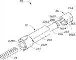
图1是本发明实施方式的光纤连接器的立体示意图。Fig. 1 is a schematic perspective view of an optical fiber connector according to an embodiment of the present invention.
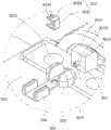
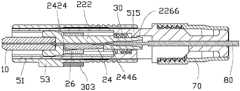
图2是图1所示光纤连接器的立体分解示意图。FIG. 2 is an exploded perspective view of the optical fiber connector shown in FIG. 1 .
图3是图2所示光纤连接器的夹持机构的立体分解示意图。FIG. 3 is an exploded perspective view of the clamping mechanism of the optical fiber connector shown in FIG. 2 .
图4是图2所示光纤连接器的夹持机构的另一视角的立体分解示意图。FIG. 4 is an exploded perspective view from another perspective of the clamping mechanism of the optical fiber connector shown in FIG. 2 .
图5是图4所示夹持机构的夹持件的放大示意图。FIG. 5 is an enlarged schematic view of a clamping part of the clamping mechanism shown in FIG. 4 .
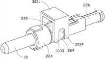
图6是图1所示光纤连接器的组装治具的立体示意图。FIG. 6 is a three-dimensional schematic diagram of an assembly jig for the optical fiber connector shown in FIG. 1 .
图7是图5所示组装治具的区域VI的局部放大图。FIG. 7 is a partially enlarged view of a region VI of the assembly jig shown in FIG. 5 .
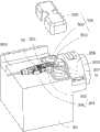
图8是图5所示组装治具组装光纤连接器时第一状态的立体示意图。FIG. 8 is a schematic perspective view of a first state when the assembly jig shown in FIG. 5 is assembling the optical fiber connector.
图9是图8所示的组装治具的拨动件插入光纤连接器时的立体示意图。FIG. 9 is a schematic perspective view of the assembly jig shown in FIG. 8 when the toggle member is inserted into the optical fiber connector.
图10是图8所示的组装治具的拨动件插入光线连接器时的部分立体示意图。FIG. 10 is a partial perspective view of the assembly jig shown in FIG. 8 when the toggle member is inserted into the optical connector.
图11是图8所示光纤连接器中装入光纤时剖视图。Fig. 11 is a cross-sectional view when an optical fiber is inserted into the optical fiber connector shown in Fig. 8 .
图12是图5所示组装治具组装光纤连接器时第二状态的立体示意图。FIG. 12 is a schematic perspective view of a second state when the assembly jig shown in FIG. 5 is assembling the optical fiber connector.
图13是图10所示光纤连接器组装光纤完毕后的状态的剖视图。Fig. 13 is a cross-sectional view of the optical fiber connector shown in Fig. 10 after the optical fiber has been assembled.
主要元件符号说明Description of main component symbols
如下具体实施方式将结合上述附图进一步说明本发明。The following specific embodiments will further illustrate the present invention in conjunction with the above-mentioned drawings.
具体实施方式Detailed ways
请参阅图1及图2,本发明实施方式的光纤连接器100为SC型光纤连接器。光纤连接器100包括光纤插芯10、光纤夹持机构20、弹性件30、壳体50及尾套70。光纤夹持机构20套设于光纤插芯10的一端,弹性件30套设于光纤夹持机构20远离光纤插芯10的一端,壳体50套设于光纤夹持机构20上,尾套70固定套设于于壳体50远离光纤插芯10的一端。壳体50开设有滑槽501。壳体50包括套壳51及外壳53,套壳51套设于光纤夹持机构20上,外壳53套设于套壳51上,尾套70固定于套壳51的一端。光纤连接器100用于夹持光纤80,光纤80包括纤芯82、形成于纤芯82表面的内覆层84,及形成于该内内覆层84表面上的外覆层86。本发明实施方式中,光纤80的部分外覆层86及部分内覆层84被剥除,且纤芯82容纳于光纤夹持机构20及光纤插芯10中,光纤夹持机构20夹持纤芯82。光纤插芯10大致呈圆柱状,其由陶瓷材料制备而成。光纤80的纤芯82穿过光纤插芯10,且伸出光纤插芯10的端部。Please refer to FIG. 1 and FIG. 2 , the
请一并参阅图3及图4,光纤夹持机构20大致呈套筒状,其用于夹持纤芯82。光纤夹持机构20包括支撑件22、与支撑件22相配合的夹持件24及套设在支撑件22及夹持件24上的锁固件26。夹持件24装设在支撑件22的一侧,且夹持件24与支撑件22配合夹持光纤80的纤芯82,锁固件26锁固支撑件22及夹持件24,以使得夹持件24及支撑件22夹紧纤芯82,且锁固件26在支撑件22和夹持件24上滑动时,能够使夹持件24及支撑件22松开夹持的纤芯82。Please refer to FIG. 3 and FIG. 4 together. The
请一并参阅图5,支撑件22包括固定部222、由固定部222靠近光纤插芯10的一端向外延伸而成的第一安装部224及由固定部222的另一端向外延伸而成的第二安装部226。固定部222的横截面大致呈矩形,固定部222一侧面上凹设有矩形的收容槽2220,其用于收容夹持件24。收容槽2220的底部沿光纤80的插入方向凹设有第一定位槽2222。固定部222靠近第一安装部224的两相对的外表面上对称凸设有两个凸起2224。本发明实施方式中,第一定位槽2222用于固定光纤80的纤芯82,第一定位槽2222为V型槽以防止纤芯82晃动,可以理解,第一定位槽2222也可以为弧形槽等。第一安装部224沿轴向方向开设有与第一定位槽2222相互连通的用于固定光纤插芯10的安装孔2240,安装孔2240的孔径较第一定位槽2222的宽度大。第二安装部226沿轴向方向开设有与第一定位槽2222相互连通的收容孔2260,第二安装部226远离固定部222的一端的外面表上凸设有卡持部2266。Please also refer to FIG. 5 , the
夹持件24大致呈矩形板状,其设置于支撑件22的收容槽2220内,并与支撑件22相配合用于夹持光纤80的纤芯82。夹持件24包括第一抵持部242及与第一抵持部242倾斜相交的第二抵持部244,第一抵持部242朝向第一定位槽2222形成有第一抵持面2422,第二抵持部244朝向第一定位槽2222形成有第二抵持面2442。第一抵持面2422上沿轴向方向凹设有与第一定位槽2222相对应的第二定位槽2424,第二抵持面2442上沿轴向方向凹设有与第二定位槽2424相互连通的导引槽2446。导引槽2446的底部为沿第二定位槽2424一端向下倾斜的斜面,因此导引槽2446的深度较第二定位槽2424的深度大,且导引槽2446的深度由远离第二定位槽2424的一端向靠近第二定位槽2424的一端逐渐加深,并延伸至第一抵持部242。本发明实施方式中,第一抵持面2422及第二抵持面2442均为平面,且相交于接合线2444。可以理解,第一抵持面2422和第二抵持面2442之间可以为过渡的圆弧面。The
可以理解,第一定位槽2222及第二定位槽2424可以省略,通过第一抵持面2422压紧纤芯82从而将纤芯82固定在光纤夹持机构20内。It can be understood that the
可以理解,导引槽2446也可设置于所述收容槽2220靠近所述第二抵持面2442的一端。It can be understood that the guiding
锁固件26大致呈圆柱状,其开设有与固定部222外轮廓相配的矩形通孔260,锁固件26相对的两个侧壁上分别凹设有一对夹持部262,且位于同一侧壁上的每对夹持部262之间形成有凸起的抵持部264。抵持部264为圆弧状凸起。靠近第一安装部224的夹持部262上对应固定部222上的两个凸起2224开设有一对锁定孔2622,固定部222上的凸起2224卡合于锁定孔2622中,从而使得锁固件26定位在固定部222上。锁固件26靠近第一安装部224一端的内壁形成一斜面2624,以便于锁固件26能够沿固定部222滑动。The locking
可以理解,锁固件26上的锁定孔2622及固定部222上的凸起2224主要用于防止锁固件26与固定部222的相对移动,锁定孔2622及凸起2224均可省略。It can be understood that the
本发明实施方式中,弹性件30为弹簧,其套设于支撑件22的第二安装部226上。套壳51呈套筒状,其套设在光纤夹持机构20上。滑槽501包括第一贯穿槽511及第二贯穿槽531。第一贯穿槽511开设于套壳51的侧壁上,第一贯穿槽511呈狭长形。套壳51的内壁上对应支撑件22的卡持部2266凸设有卡合部515。外壳53大致呈长方体套筒状,其套设在套壳51上,第二贯穿槽531开设于外壳53对应第一贯穿槽511的侧壁上,第二贯穿槽531的形状与第一贯穿槽511类似且相互连通,且每个第一贯穿槽511及对应的第二贯穿槽531分别与位于锁固件26同一侧壁上的一对夹持部262相对。尾套70呈圆筒状,尾套70螺接于套壳51远离外壳53的一端。可以理解,壳体50可只包括外壳53,套壳51可省略,壳体50对应抵持部264开设有贯穿槽。In the embodiment of the present invention, the
组装光纤连接器100时,先组装光纤夹持机构20,夹持件24对应收容于支撑件22的收容槽2220内,并使得第一定位槽2222与第二定位槽2424相对应;然后将锁固件26套设于支撑件22的固定部222上,并使得锁固件26位于固定部222靠近第二安装部226的一端,将光纤插芯10固定于安装孔2240内,将弹性件30套设于支撑件22的第二安装部226上;将上述安装有光纤插芯10的夹持件24装入套壳51,并使得支撑件22上的卡持部2266与套壳51的卡合部46相卡合,此时,弹性件30的一端抵持套壳51的卡合部46,其另一端抵持支撑件22的固定部222的末端,从而将光纤夹持机构20固定于套壳51内;将外壳53套设于套壳51上,并使得外壳53的第二贯穿槽531与套壳51的第一贯穿槽511相对应,最后将尾套70固定至套壳51的末端,即完成光纤连接器100的组装。When assembling the optical fiber connector 100, first assemble the optical fiber clamping mechanism 20, the clamping member 24 is correspondingly accommodated in the receiving groove 2220 of the support member 22, and makes the first positioning groove 2222 correspond to the second positioning groove 2424; The fastener 26 is sleeved on the fixing part 222 of the support member 22, and the locking member 26 is located at the end of the fixing part 222 close to the second installation part 226, the optical fiber ferrule 10 is fixed in the installation hole 2240, and the elastic member 30 is sleeved On the second mounting portion 226 of the support member 22; the above-mentioned clamping member 24 installed with the optical fiber ferrule 10 is installed into the casing 51, and the clamping portion 2266 on the support member 22 is engaged with the engaging portion of the casing 51 46, at this time, one end of the elastic member 30 is against the engaging portion 46 of the casing 51, and the other end is against the end of the fixing portion 222 of the support member 22, thereby fixing the optical fiber clamping mechanism 20 to the casing 51; set the shell 53 on the casing 51, and make the second through groove 531 of the shell 53 correspond to the first through groove 511 of the casing 51, and finally fix the tail sleeve 70 to the end of the casing 51, That is, the assembly of the optical fiber connector 100 is completed.
请同时参阅图6及图7,光纤连接器100的现地组装治具300包括本体301、拨动件303、装设于本体301上的夹持件304、推抵件307、弹性件(图未示)及驱动件308。夹持件304、推抵件307及驱动件308大致位于同一条直线上。拨动件303用于拨动光纤连接器100中的锁固件26。夹持件304用于夹持光纤连接器100,驱动件308与推抵件307通过弹性件连接。驱动件308用于驱动推抵件307伸缩。推抵件307用于弹性推抵装设于光纤连接器100中的纤芯82。本体301大致为块状,其形成有一个安装面3011。安装面3011一端凸伸形成有安装部3012,安装部3012开设有一个贯穿孔3013,用于装设推抵件307。Please refer to FIG. 6 and FIG. 7 at the same time. The on-
拨动件303包括主体3031及于主体3031相对的两侧垂直延伸形成的一对卡合部3033。主体3031及卡合部3033均大致为矩形片状。一对卡合部3033相对设置,且一对卡合部3033之间的宽度大致等于锁固件26相对两侧的夹持部262之间的宽度。每个卡合部3033远离主体3031的一端开设有一个卡合槽3034,用于卡合部3033与锁固件26配合时,使得锁固件26的抵持部264卡合于卡合槽3034中。The
夹持件304包括一对第一夹持部305及一对第二夹持部306。一对第一夹持部305及一对第二夹持部306分别凸伸于本体301的安装面3011上,且一对第一夹持部305相对设置,一对第二夹持部306相对设置。第一夹持部305及第二夹持部306均为凸起,且第一夹持部与第二夹持部306设置在一条直线上,用于将光纤连接器100夹设在一对第一夹持部305与一对第二夹持部306之间。一对第一夹持部305之间的距离等于光纤连接器100的外壳53远离尾套70一端的宽度,一对第二夹持部之间的距离等于光纤连接器100的外壳53靠近尾套70一端的宽度。The clamping
推抵件307可活动地穿设于安装部3012的贯穿孔3013中,且推抵件307朝向第一夹持部305的一端伸出安装部3012。推抵件307朝向第一夹持部305的一端形成有一个推抵端面3071,推抵件307在推抵端面3071上凹设有一个容纳槽3073。容纳槽3073为微米级深度的凹槽,在本实施方式中,容纳槽3073的深度为3微米。推抵件307远离第一夹持部305的一端与驱动件308通过弹性件连接。驱动件308固定装设在本体301远离第二夹持部306的一端,且能够驱动推抵件307沿着贯穿孔3013自由伸缩。在本实施方式中,驱动件308为一个凸轮。弹性件为弹簧。可以理解,驱动件308可为其他能够驱动推抵件307伸缩的驱动结构,例如丝杆等。驱动件308与推抵件307之间可以通过设置其他弹性件实现弹性连接,如橡胶块等。The pushing
请同时参阅图8,在本实施方式中,现地组装治具300用于对光纤连接器100在现地电弧加热处理后进行快速组装。所以本体301上还开设有位于推抵件307两侧的一对安装孔3015(如图7),用于安装端面处理设备500。端面处理设备500包括一对装设于一对安装孔3015的安装部502、装设于一对安装部502的一对放电电极503、遮盖放电电极503的防护罩505以及控制放电电极503放电的控制装置(图未示)。一对放电电极503相对设置,且放电电极503靠近推抵件307的推抵端面3071。Please refer to FIG. 8 at the same time. In this embodiment, the
请同时参阅图9至图11,现地对光纤进行端面处理并快速组装时,先将光纤连接器100放置在一对第一夹持部305及一对第二夹持部306之间,第一夹持部305卡持外壳53远离尾套70的一端,第二夹持部306卡持外壳53靠近尾套70的一端。然后将拨动件303的一对卡合部3033从一对第二贯穿槽531伸入光纤连接器100,卡合部3033穿过第一贯穿槽511后与锁固件26的两对夹持部262抵持,同时,锁固件26的抵持部264卡合于拨动件303的卡合槽3034中。操作者滑动拨动件303沿第一贯穿槽511朝向固定部222靠近第二安装部226的一端移动,拨动件303带动锁固件26滑动,锁固件26压抵夹持件24,并使得夹持件24的第二抵持面2442朝向固定部222的收容槽2220的底部移动,锁固件26上的锁定孔2622与固定部222上的凸起2224解除卡合,夹持件24的第二抵持面2442压抵固定部222的收容槽2220的底部,从而锁固件26解除锁固固定部222和夹持件24。取下尾套70,然后将光纤80从尾套70的末端插入光纤夹持机构20。此时夹持件24的第一抵持面2422翘起,从而使得第二定位槽2424与第一定位槽2222之间出现一定的间隙,纤芯82经由导引槽2446及所述间隙通过光纤夹持机构20。继续插入光纤80至纤芯82从光纤插芯10伸出。本实施方式中光纤80的纤芯82从光纤插芯10中伸出至大致位于一对放电电极503之间。Please refer to FIGS. 9 to 11 at the same time. When performing end-face treatment on the optical fiber and quickly assembling it, first place the
请同时参阅图12,驱动件308驱动推抵件307,由于驱动件308与推抵件307之间设置有弹性件,推抵件307的推抵端面3071弹性抵持推抵光纤纤芯82,光纤纤芯82的端面容纳于容纳槽3073中。驱动件308驱动至将纤芯82的端部准确定位于一对放电电极503之间(请参阅图7),此时,组装治具300位于第一状态。启动端面处理设备500,放电电极503放电对光纤纤芯82的端面进行放电处理。放电后,驱动件308继续驱动推抵件307弹性抵持光纤纤芯82至推抵端面3071与光纤插芯10的端面相抵持(请参阅图10),此时组装治具300位于第二状态。继而驱动件308驱动推抵件307回位至初始位置。此时,光纤纤芯82伸出光纤插芯10端面的长度等于容纳槽3073的深度。Please refer to FIG. 12 at the same time. The driving
请同时参阅图13,操作者滑动拨动件303沿第一贯穿槽511朝向固定部222靠近第一安装部224的一端移动,拨动件303带动锁固件26滑动,锁固件26压抵夹持件24,并使得夹持件24的第一抵持面2422朝向固定部222的收容槽2220的底部移动,继续推动拨动件303直至锁固件26上的锁定孔2622与固定部222上的凸起2224相卡合,夹持件24的第一抵持面2422压抵固定部222的收容槽2220的底部,从而固定收容于第一定位槽2222内的光纤80的纤芯82。然后安装尾套70,尾套70的末端夹持光纤80的外覆层86,以进一步固定光纤80。Please also refer to FIG. 13 , the operator slides the
可以理解,锁固件26可只于一个侧壁上凹设有一对夹持部262,则夹持部262之间的抵持部264也只为一个,相对应地,套壳51与外壳53也可只开设一个与夹持部262相对的第一贯穿槽511及第二贯穿槽531,同时,拨动件303的卡合部3033也只需一对,或卡合槽3034直接开设在主体3031上,且省略卡合部3033。It can be understood that the locking
本发明的光纤连接器100,由于锁固件26在固定部222上滑动能够锁紧或松开夹持的纤芯82,使得锁固件26上的夹持部262及抵持部264与现地组装治具300的拨动件303配合,能够较容易地松开纤芯82,从而在现地对光纤80的端面进行加工后,在驱动件308及推抵件307的配合下,能够将现地将纤芯82推至所需位置,继而拨动件303驱动锁固件26夹紧纤芯82,从而能够快速、方便地实现光纤的现地组装。In the
本领域技术人员还可在本发明精神内做其它变化,当然,这些依据本发明精神所做的变化,都应包含在本发明所要求保护的范围内。Those skilled in the art can also make other changes within the spirit of the present invention, and of course, these changes made according to the spirit of the present invention should all be included in the scope of protection claimed by the present invention.
Claims (10)
Translated fromChinesePriority Applications (5)
| Application Number | Priority Date | Filing Date | Title |
|---|---|---|---|
| CN201210100974.8ACN103364886B (en) | 2012-04-09 | 2012-04-09 | Optical-fiber connector and assembling fixture used by optical-fiber connector |
| TW101112985ATWI479216B (en) | 2012-04-09 | 2012-04-12 | Optical fiber connector and assembly tool thereof |
| US13/792,215US8876406B2 (en) | 2012-04-09 | 2013-03-11 | Optical fiber connector and assembling device for the same |
| JP2013078615AJP2013218328A (en) | 2012-04-09 | 2013-04-04 | Optical fiber connector and assembling tool for construction site to be used for the same |
| US14/493,372US9581771B2 (en) | 2012-04-09 | 2014-09-23 | Assembling device for the optical fiber connector |
Applications Claiming Priority (1)
| Application Number | Priority Date | Filing Date | Title |
|---|---|---|---|
| CN201210100974.8ACN103364886B (en) | 2012-04-09 | 2012-04-09 | Optical-fiber connector and assembling fixture used by optical-fiber connector |
Publications (2)
| Publication Number | Publication Date |
|---|---|
| CN103364886Atrue CN103364886A (en) | 2013-10-23 |
| CN103364886B CN103364886B (en) | 2015-03-11 |
Family
ID=49292371
Family Applications (1)
| Application Number | Title | Priority Date | Filing Date |
|---|---|---|---|
| CN201210100974.8AActiveCN103364886B (en) | 2012-04-09 | 2012-04-09 | Optical-fiber connector and assembling fixture used by optical-fiber connector |
Country Status (4)
| Country | Link |
|---|---|
| US (2) | US8876406B2 (en) |
| JP (1) | JP2013218328A (en) |
| CN (1) | CN103364886B (en) |
| TW (1) | TWI479216B (en) |
Cited By (6)
| Publication number | Priority date | Publication date | Assignee | Title |
|---|---|---|---|---|
| CN105022122A (en)* | 2015-04-29 | 2015-11-04 | 中航光电科技股份有限公司 | Manufacturing device and manufacturing method for contact element component of polarization-maintaining optical fiber connector |
| CN105278048A (en)* | 2014-07-25 | 2016-01-27 | 鸿富锦精密工业(深圳)有限公司 | Optical fiber connector assembling jig |
| CN111323062A (en)* | 2020-04-28 | 2020-06-23 | 深圳市特发信息股份有限公司 | Installation mechanism of multichannel optical fiber early warning equipment |
| CN113296193A (en)* | 2020-02-21 | 2021-08-24 | 立佳兴业股份有限公司 | Optical connector and optical connector module thereof |
| WO2024160065A1 (en)* | 2023-02-03 | 2024-08-08 | 华为技术有限公司 | Optical fiber connector, connector assembly and optical communication device |
| CN119511473A (en)* | 2024-12-11 | 2025-02-25 | 无锡鑫巨宏智能科技股份有限公司 | A fiber optic module that uses optical plastic lenses to achieve fast and precise assembly |
Families Citing this family (11)
| Publication number | Priority date | Publication date | Assignee | Title |
|---|---|---|---|---|
| CN103364883B (en)* | 2012-04-09 | 2015-04-15 | 鸿富锦精密工业(深圳)有限公司 | Optical fiber connector |
| CN103364885B (en)* | 2012-04-09 | 2015-05-20 | 鸿富锦精密工业(深圳)有限公司 | Optical-fiber clamping mechanism and optical-fiber connector using optical-fiber clamping mechanism |
| TWI514020B (en)* | 2014-04-11 | 2015-12-21 | Cn J Technology Co Ltd | Wiring tool for optical fiber connector |
| CN104020531B (en)* | 2014-06-24 | 2015-09-09 | 上海鸿辉光通科技股份有限公司 | A kind of rapid-assembling device for SC type fiber active linker |
| TWM520643U (en)* | 2015-11-27 | 2016-04-21 | Amphenol Fiber Optic China | The optical fiber connector |
| EP3460548A1 (en) | 2017-09-25 | 2019-03-27 | Fujikura Ltd. | Clamp member, optical connector, and manufacturing method of optical connector |
| JP2019086572A (en)* | 2017-11-02 | 2019-06-06 | 株式会社フジクラ | Optical connector, gripping member, and method of manufacturing optical connector |
| CN107728276A (en)* | 2017-11-23 | 2018-02-23 | 苏州专创光电科技有限公司 | A kind of optical connector with dust reduction capability |
| CN109596039B (en)* | 2018-12-29 | 2024-05-17 | 苏州松翔电通科技有限公司 | Measuring device for detecting flatness of optical module |
| CN113211281A (en)* | 2021-04-19 | 2021-08-06 | 东莞市新美洋技术有限公司 | Polishing device |
| WO2023205045A1 (en)* | 2022-04-18 | 2023-10-26 | Ortronics, Inc. | System for fiber connector assembly |
Citations (4)
| Publication number | Priority date | Publication date | Assignee | Title |
|---|---|---|---|---|
| EP1612589A1 (en)* | 2004-06-30 | 2006-01-04 | Tyco Electronics Corporation | Small form factor field-installable optical connector |
| CN1742219A (en)* | 2003-02-17 | 2006-03-01 | 住友电气工业株式会社 | Fiber Connection Fixture |
| CN202171660U (en)* | 2011-07-01 | 2012-03-21 | 泰科电子(上海)有限公司 | Optical fiber connection component and optical fiber connector including the same |
| CN102955206A (en)* | 2011-08-29 | 2013-03-06 | 鸿富锦精密工业(深圳)有限公司 | Optical fiber connector |
Family Cites Families (15)
| Publication number | Priority date | Publication date | Assignee | Title |
|---|---|---|---|---|
| US4486072A (en)* | 1982-01-12 | 1984-12-04 | Augat Inc. | Optical connector and splicing device using double diameter resilient rods |
| JPH0516563Y2 (en)* | 1988-12-28 | 1993-04-30 | ||
| JPH082643Y2 (en)* | 1992-06-22 | 1996-01-29 | アンプ インコーポレイテッド | Optical fiber connector |
| US6464408B1 (en)* | 1998-12-28 | 2002-10-15 | Computer Crafts, Inc. | Fiber optic connectors |
| JP4059606B2 (en)* | 2000-03-03 | 2008-03-12 | パイロットプレシジョン株式会社 | Optical connector |
| JP2002072011A (en)* | 2000-06-15 | 2002-03-12 | Pilot Precision Co Ltd | Optical fiber holding apparatus |
| US7158712B2 (en)* | 2005-05-06 | 2007-01-02 | Coretech Optical Co., Ltd. | Optical fiber coupler and manufacturing apparatus and method thereof |
| WO2007050470A1 (en)* | 2005-10-24 | 2007-05-03 | 3M Innovative Properties Company | Optical connector, fiber distribution unit, and fiber termination platform for optical connectors |
| US7194179B1 (en)* | 2005-12-27 | 2007-03-20 | 3M Innovative Properties Company | Assembly tool and optical connector assembly method |
| JP4822949B2 (en)* | 2006-06-20 | 2011-11-24 | モレックス インコーポレイテド | Optical ferrule assembly |
| US7775726B2 (en)* | 2007-02-16 | 2010-08-17 | 3M Innovative Properties Company | Remote grip optical fiber connector |
| CN101728686A (en)* | 2008-10-21 | 2010-06-09 | 鸿富锦精密工业(深圳)有限公司 | Connector |
| JP4908480B2 (en)* | 2008-11-10 | 2012-04-04 | 住友電気工業株式会社 | Optical connection cable gripping member |
| US8442375B2 (en)* | 2009-06-16 | 2013-05-14 | 3M Innovative Properties Company | Assembly tool and optical connector assembly method |
| US8459880B2 (en)* | 2009-07-31 | 2013-06-11 | Corning Cable Systems Llc | Fiber optic connectors, cable assemblies and methods for making the same |
- 2012
- 2012-04-09CNCN201210100974.8Apatent/CN103364886B/enactiveActive
- 2012-04-12TWTW101112985Apatent/TWI479216B/enactive
- 2013
- 2013-03-11USUS13/792,215patent/US8876406B2/enactiveActive
- 2013-04-04JPJP2013078615Apatent/JP2013218328A/enactivePending
- 2014
- 2014-09-23USUS14/493,372patent/US9581771B2/ennot_activeExpired - Fee Related
Patent Citations (4)
| Publication number | Priority date | Publication date | Assignee | Title |
|---|---|---|---|---|
| CN1742219A (en)* | 2003-02-17 | 2006-03-01 | 住友电气工业株式会社 | Fiber Connection Fixture |
| EP1612589A1 (en)* | 2004-06-30 | 2006-01-04 | Tyco Electronics Corporation | Small form factor field-installable optical connector |
| CN202171660U (en)* | 2011-07-01 | 2012-03-21 | 泰科电子(上海)有限公司 | Optical fiber connection component and optical fiber connector including the same |
| CN102955206A (en)* | 2011-08-29 | 2013-03-06 | 鸿富锦精密工业(深圳)有限公司 | Optical fiber connector |
Cited By (9)
| Publication number | Priority date | Publication date | Assignee | Title |
|---|---|---|---|---|
| CN105278048A (en)* | 2014-07-25 | 2016-01-27 | 鸿富锦精密工业(深圳)有限公司 | Optical fiber connector assembling jig |
| CN105278048B (en)* | 2014-07-25 | 2017-05-24 | 鸿富锦精密工业(深圳)有限公司 | Optical fiber connector assembling jig |
| CN105022122A (en)* | 2015-04-29 | 2015-11-04 | 中航光电科技股份有限公司 | Manufacturing device and manufacturing method for contact element component of polarization-maintaining optical fiber connector |
| CN113296193A (en)* | 2020-02-21 | 2021-08-24 | 立佳兴业股份有限公司 | Optical connector and optical connector module thereof |
| CN113296193B (en)* | 2020-02-21 | 2023-03-21 | 立佳兴业股份有限公司 | Optical connector and optical connector module thereof |
| CN111323062A (en)* | 2020-04-28 | 2020-06-23 | 深圳市特发信息股份有限公司 | Installation mechanism of multichannel optical fiber early warning equipment |
| CN111323062B (en)* | 2020-04-28 | 2021-08-06 | 深圳市特发信息股份有限公司 | Installation mechanism of multichannel optical fiber early warning equipment |
| WO2024160065A1 (en)* | 2023-02-03 | 2024-08-08 | 华为技术有限公司 | Optical fiber connector, connector assembly and optical communication device |
| CN119511473A (en)* | 2024-12-11 | 2025-02-25 | 无锡鑫巨宏智能科技股份有限公司 | A fiber optic module that uses optical plastic lenses to achieve fast and precise assembly |
Also Published As
| Publication number | Publication date |
|---|---|
| JP2013218328A (en) | 2013-10-24 |
| TWI479216B (en) | 2015-04-01 |
| US20130266276A1 (en) | 2013-10-10 |
| CN103364886B (en) | 2015-03-11 |
| US8876406B2 (en) | 2014-11-04 |
| US9581771B2 (en) | 2017-02-28 |
| US20150043873A1 (en) | 2015-02-12 |
| TW201341876A (en) | 2013-10-16 |
Similar Documents
| Publication | Publication Date | Title |
|---|---|---|
| CN103364886B (en) | Optical-fiber connector and assembling fixture used by optical-fiber connector | |
| CN103364884B (en) | The joints of optical fibre | |
| US11397297B2 (en) | Optical assembly with cable retainer | |
| CN103364885B (en) | Optical-fiber clamping mechanism and optical-fiber connector using optical-fiber clamping mechanism | |
| CN101617255B (en) | Remote Grip Fiber Optic Connectors | |
| CN103257408B (en) | Optical fiber connector and auxiliary pulling-out device for optical fiber connector | |
| JP4099228B2 (en) | Fiber optic connector for fibers having cleaved / chamfered ends | |
| CN103364887B (en) | Optical-fiber connector | |
| CN103576250B (en) | Fiber optic connector assembly | |
| CN102928931B (en) | Optical fiber connector and mounting tool for same | |
| JP4800136B2 (en) | Optical receptacle housing, optical connector receptacle and optical device | |
| CN103364883B (en) | Optical fiber connector | |
| CN102955206B (en) | Optical fiber connector | |
| CN103969753B (en) | The joints of optical fibre | |
| CN100580492C (en) | Inner housing for optical waveguide plug-in connectors | |
| CN103364874B (en) | Fibre-optical process equipment and optical fiber now assemble method | |
| CN102859409A (en) | Optocoupler structure, and optocoupler structure assembly method | |
| CN105278047A (en) | Optical fiber connector | |
| CN103364881B (en) | Optical-fiber end face processing device and optical-fiber positioning structure thereof | |
| JP4446782B2 (en) | Optical connection structure and manufacturing method thereof | |
| JP3622487B2 (en) | Optical connector assembly method | |
| JP2007256777A (en) | Optical connector | |
| JP2009020236A (en) | Connection holder and connection structure between optical fiber connector and optoelectronic component using the connection holder | |
| JPH03118507A (en) | How to fix the ferrule | |
| JPH10239560A (en) | Optical connector connection tool |
Legal Events
| Date | Code | Title | Description |
|---|---|---|---|
| C06 | Publication | ||
| PB01 | Publication | ||
| C10 | Entry into substantive examination | ||
| SE01 | Entry into force of request for substantive examination | ||
| C14 | Grant of patent or utility model | ||
| GR01 | Patent grant | ||
| TR01 | Transfer of patent right | ||
| TR01 | Transfer of patent right | Effective date of registration:20170605 Address after:Jincheng economic and Technological Development Zone, Shanxi Patentee after:Fu Jin Precision Industry (Jincheng) Co., Ltd. Address before:518109 Guangdong city of Shenzhen province Baoan District Longhua Town Industrial Zone tabulaeformis tenth East Ring Road No. 2 two Co-patentee before:Hon Hai Precision Industry Co., Ltd. Patentee before:Hongfujin Precise Industry (Shenzhen) Co., Ltd. |