CN103359283A - High-reliability unmanned aerial vehicle with tilt rotors - Google Patents
High-reliability unmanned aerial vehicle with tilt rotorsDownload PDFInfo
- Publication number
- CN103359283A CN103359283ACN2013102731488ACN201310273148ACN103359283ACN 103359283 ACN103359283 ACN 103359283ACN 2013102731488 ACN2013102731488 ACN 2013102731488ACN 201310273148 ACN201310273148 ACN 201310273148ACN 103359283 ACN103359283 ACN 103359283A
- Authority
- CN
- China
- Prior art keywords
- motor
- flight control
- rotor
- unmanned aerial
- aerial vehicle
- Prior art date
- Legal status (The legal status is an assumption and is not a legal conclusion. Google has not performed a legal analysis and makes no representation as to the accuracy of the status listed.)
- Pending
Links
- RZVHIXYEVGDQDX-UHFFFAOYSA-N9,10-anthraquinoneChemical compoundC1=CC=C2C(=O)C3=CC=CC=C3C(=O)C2=C1RZVHIXYEVGDQDX-UHFFFAOYSA-N0.000claimsabstractdescription36
- 238000005259measurementMethods0.000claimsdescription6
- 238000004146energy storageMethods0.000claimsdescription4
- 230000009977dual effectEffects0.000description3
- 230000003139buffering effectEffects0.000description2
- 238000010586diagramMethods0.000description2
- 230000009286beneficial effectEffects0.000description1
- 238000007689inspectionMethods0.000description1
- 238000011835investigationMethods0.000description1
- 231100000225lethalityToxicity0.000description1
- 238000012423maintenanceMethods0.000description1
- 238000000034methodMethods0.000description1
Images


Landscapes
- Toys (AREA)
Abstract
Translated fromChinese
Description
Translated fromChinese技术领域technical field
本发明涉及一种多旋翼无人飞行器。特别是涉及一种高可靠性倾转旋翼无人飞行器。The invention relates to a multi-rotor unmanned aerial vehicle. In particular, it relates to a high-reliability tilt-rotor unmanned aerial vehicle.
背景技术Background technique
多旋翼飞行器,国外又称Multi-rotor,是一种具有多个螺旋桨的飞行器,与传统的直升机不同,多旋翼飞行器通过改变螺旋桨的速度来实现各种动作。Multi-rotor aircraft, also known as Multi-rotor abroad, is an aircraft with multiple propellers. Unlike traditional helicopters, multi-rotor aircraft achieves various actions by changing the speed of the propellers.
具有垂直起降和悬停能力的旋翼飞行器,较之传统单旋翼直升机,具有结构简单、维护容易,桨叶杀伤力小,操作安全的特点。不但在军事领域发挥着日益重要的作用,也在灾害救援、评估,危险环境调查,交通巡视及空中摄影等多个民用领域得到广泛的应用。Compared with traditional single-rotor helicopters, the rotorcraft with vertical take-off and landing and hovering capabilities has the characteristics of simple structure, easy maintenance, small blade lethality, and safe operation. Not only is it playing an increasingly important role in the military field, but it is also widely used in many civilian fields such as disaster rescue, assessment, dangerous environment investigation, traffic inspection and aerial photography.
现有的多旋翼无人飞行器,在任一套动力装置出现故障的情况下,均将无法维持姿态稳定而坠毁,通过简单的概率计算可以得出,多旋翼飞行器系统的整体可靠性远低于固定翼飞行器及普通单旋翼飞行器,这极大的限制了多旋翼飞行器的应用领域。例如,在需要搭载昂贵设备的飞行任务中,尽管多旋翼飞行器有诸多优点,仍然被排除在选择范围外。Existing multi-rotor unmanned aerial vehicles, in the case of failure of any set of power devices, will not be able to maintain a stable attitude and crash. Through simple probability calculations, it can be concluded that the overall reliability of multi-rotor aircraft systems is much lower than that of fixed-rotor aircraft systems. Wing aircraft and ordinary single-rotor aircraft, which greatly limits the application field of multi-rotor aircraft. For example, in missions that require carrying expensive equipment on board, multirotors, despite their many advantages, are still ruled out as an option.
另一方面,目前多旋翼无人飞行器均为固定构型,飞行器面积大,不利于在狭小空间飞行。On the other hand, the current multi-rotor unmanned aerial vehicles are all in a fixed configuration, and the area of the aircraft is large, which is not conducive to flying in a small space.
发明内容Contents of the invention
本发明所要解决的技术问题是,提供一种能够大大提高多旋翼飞行器可靠性的高可靠性倾转旋翼无人飞行器。The technical problem to be solved by the present invention is to provide a high-reliability tilt-rotor unmanned aircraft that can greatly improve the reliability of the multi-rotor aircraft.
本发明所采用的技术方案是:一种高可靠性倾转旋翼无人飞行器,包括有机架,所述的机架的中心设置有飞行控制系统,所述的机架是由三个相同的机臂对接组成的Y字型机架,每一个机臂的端部都设置一组与飞行控制系统电连接并能够旋转设定角度的电动动力单元。The technical solution adopted in the present invention is: a high-reliability tilt-rotor unmanned aerial vehicle, including a frame, the center of the frame is provided with a flight control system, and the frame is composed of three identical A Y-shaped frame composed of docked arms, each end of the arm is provided with a group of electric power units that are electrically connected to the flight control system and can rotate to set an angle.
所述的每一个机臂上还设置有在飞行器着地时具有缓冲作用的起落装置。Each arm is also provided with a landing gear with a buffering effect when the aircraft touches the ground.
所述的电动动力单元包括有能够旋转的连接在机臂端部的电机座,固定在电机座上的永磁无刷直流电机和连接在永磁无刷直流电机输出轴上的旋翼,以及连接在电机座一侧用于驱动电机座以机臂为轴进行旋转的电机转向伺服器,所述的永磁无刷直流电机和电机转向伺服器的输入端电连接飞行控制系统的输出端。The electric power unit includes a rotatable motor base connected to the end of the machine arm, a permanent magnet brushless DC motor fixed on the motor base and a rotor connected to the output shaft of the permanent magnet brushless DC motor, and a connecting On the side of the motor base, the motor steering servo is used to drive the motor base to rotate with the machine arm as the axis. The permanent magnet brushless DC motor and the input end of the motor steering servo are electrically connected to the output end of the flight control system.
所述旋翼的叶片为对称翼型或非对称翼型。The blades of the rotor are symmetrical airfoils or asymmetrical airfoils.
所述的机臂为中空结构,所述中空结构内置有飞行控制系统分别与电机转向私服器和电动动力单元中的永磁无刷直流电机之间的连接导线。The arm is a hollow structure, and the hollow structure is built with connecting wires between the flight control system and the motor steering server and the permanent magnet brushless DC motor in the electric power unit.
所述Y字型的机架的中心固定设置有中心板,所述的飞行控制系统固定设置在所述的中心板上。A center plate is fixedly arranged in the center of the Y-shaped frame, and the flight control system is fixedly arranged on the center plate.
所述的飞行控制系统包括有飞行控制单元,与飞行控制单元的信号输出端相连接的用于驱动电动动力单元中的永磁无刷直流电机的驱动单元,以及与所述的驱动单元相连用于提供电源的储能动力电池,所述的飞行控制单元的信号输出端还连接电动动力单元中的电机转向私服器。The flight control system includes a flight control unit, a drive unit connected to the signal output end of the flight control unit for driving the permanent magnet brushless DC motor in the electric power unit, and a drive unit connected with the drive unit For the energy storage power battery that provides power, the signal output end of the flight control unit is also connected to the motor steering server in the electric power unit.
所述的飞行控制单元包括有处理器,分别连接处理器的惯性测量模块和数据收发模块,所述处理器的输出信号分别连接驱动单元和电动动力单元中的电机转向私服器。The flight control unit includes a processor, which is respectively connected to the inertial measurement module and the data transceiver module of the processor, and the output signal of the processor is respectively connected to the motor steering server in the drive unit and the electric power unit.
本发明的一种高可靠性倾转旋翼无人飞行器,通过对每个旋翼倾转角度的控制,在某一旋翼失效后具有保持姿态稳定的能力,飞行器构型可变,如从三旋翼水平构型可转换为双旋翼竖直构型,可以减小飞行器投影面积,更适合在有限空间里飞行。本发明具有如下有益效果:A high-reliability tilt-rotor unmanned aerial vehicle of the present invention has the ability to maintain a stable attitude after a certain rotor fails by controlling the tilt angle of each rotor. The configuration can be converted to a dual-rotor vertical configuration, which can reduce the projected area of the aircraft and is more suitable for flying in a limited space. The present invention has following beneficial effect:
1、大大提高了多旋翼飞行器可靠性,在有一组动力单元失效的情况下,通过伺服器转动剩余动力单元,切换飞行模式后仍可以稳定飞行器的姿态,保证飞行器能安全降落,从而保护了地面人员及机载设备;1. The reliability of the multi-rotor aircraft has been greatly improved. In the case of failure of one group of power units, the attitude of the aircraft can still be stabilized after switching the flight mode by turning the remaining power units through the servo to ensure that the aircraft can land safely, thereby protecting the ground personnel and airborne equipment;
2、当飞行器遇到狭小的空间需要穿过时,也可以切换为双动力单元飞行方式,从而拓展了多旋翼飞行器的使用范围。2. When the aircraft encounters a narrow space and needs to pass through, it can also switch to the dual power unit flight mode, thereby expanding the use range of the multi-rotor aircraft.
附图说明Description of drawings
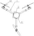
图1是本发明的整体结构示意图;Fig. 1 is the overall structural representation of the present invention;
图2是本发明处于双电动动力单元构型时的示意图;Fig. 2 is the schematic diagram when the present invention is in double electric power unit configuration;
图3是本发明的飞行控制系统构成框图。Fig. 3 is a block diagram of the flight control system of the present invention.
1:机架 11:机臂1: Frame 11: Arm
12:电动动力单元 121:电机座12: Electric power unit 121: Motor base
122:永磁无刷直流电机 123:旋翼122: Permanent magnet brushless DC motor 123: Rotor
124:电机转向伺服器 2:飞行控制系统124: Motor steering servo 2: Flight control system
21:飞行控制单元 22:驱动单元21: Flight control unit 22: Drive unit
23:储能动力电池 24:电机转向私服器23: Energy storage power battery 24: Motor steering private server
211:处理器 212:惯性测量模块211: Processor 212: Inertial Measurement Module
213:数据收发模块213: Data transceiver module
具体实施方式Detailed ways
下面结合实施例和附图对本发明的一种高可靠性倾转旋翼无人飞行器做出详细说明。A high-reliability tilt-rotor unmanned aerial vehicle of the present invention will be described in detail below in conjunction with the embodiments and accompanying drawings.
本发明的一种高可靠性倾转旋翼无人飞行器,包括有机架1,所述的机架1的中心设置有飞行控制系统2,所述的机架1是由三个相同的机臂11对接组成的Y字型机架,每一个机臂11的端部都设置一组与飞行控制系统2电连接并能够旋转设定角度的电动动力单元12。三个电动动力单元12形成一个等边三角形。为了保证无人飞行器着路时的稳定性,所述的每一个机臂11上还设置有在飞行器着地时具有缓冲作用的起落装置3。A kind of high-reliability tilt-rotor unmanned aerial vehicle of the present invention comprises
所述的电动动力单元12包括有能够以机臂11为轴旋转的连接在机臂11端部的电机座121,固定在电机座121上的永磁无刷直流电机122和连接在永磁无刷直流电机122输出轴上的旋翼123,以及连接在电机座121一侧用于驱动电机座121以机臂11为轴进行旋转的电机转向伺服器124,所述的永磁无刷直流电机122和电机转向伺服器124的输入端电连接飞行控制系统2的输出端。所述旋翼123的叶片为对称翼型或非对称翼型。The
所述的机臂11为中空结构,所述中空结构内置有飞行控制系统2分别与电机转向伺服器124和电动动力单元12中的永磁无刷直流电机122之间的连接导线。从而使整机外部没有导线,整体简洁,安全。The
所述Y字型的机架1的中心固定设置有中心板4,所述的飞行控制系统2固定设置在所述的中心板4上。所述的飞行控制系统2包括有飞行控制单元21,与飞行控制单元21的信号输出端相连接的用于驱动电动动力单元12中的永磁无刷直流电机122的驱动单元22,以及与所述的驱动单元22相连用于提供电源的储能动力电池23,所述的飞行控制单元21的信号输出端还连接电动动力单元12中的电机转向私服器124。A
其中,所述的驱动单元22可以采用型号为Hobbywing Skywalker40A或ZTW AL30A或Align REC-BL35P的驱动模块。Wherein, the
具体的是所述的飞行控制单元21包括有处理器211,分别连接处理器211的惯性测量模块212和数据收发模块213,所述处理器211的输出信号分别连接驱动单元22和电动动力单元12中的电机转向私服器13。Specifically, the
其中,所述的惯性测量模块212可以采用型号为Xsens MTI或Crossbow NAV440或VMsens VM-i的惯性测量模块。所述的处理器211以采用型号为STMicroelectronicsSTM32F103或STMicroelectronics STM32F405或Atmel ATmega2560-16AU的处理器。所述的数据收发模块213以采用型号为YL-100IL或FY-602或RSD-500T的模块。Wherein, the
本发明的一种高可靠性倾转旋翼无人飞行器,的工作原理是:正常飞行时,无人飞行器的三个电动动力单元中的两个处于在同一平面,另一个动力单元在电机转向伺服器的驱动下旋转一定角度,实现扭矩的平衡及姿态控制;当三个电动动力单元之一发生故障时,无人飞行器切换为双电动动力单元飞行方式,通过剩余两套电动动力单元的摆动稳定飞行姿态,使无人飞行器安全着陆。当无人飞行器遇到狭小的空间需要穿过时,也可以切换为双电动动力单元的飞行方式。A kind of high-reliability tilt-rotor unmanned aerial vehicle of the present invention, the working principle is: during normal flight, two of the three electric power units of the unmanned aerial vehicle are in the same plane, and the other power unit is in the motor steering servo Driven by the UAV, it rotates at a certain angle to achieve torque balance and attitude control; when one of the three electric power units fails, the unmanned aerial vehicle switches to the dual electric power unit flight mode, and stabilizes the aircraft through the swing of the remaining two electric power units. The flight attitude enables the unmanned aerial vehicle to land safely. When the unmanned aerial vehicle encounters a narrow space and needs to pass through, it can also switch to the flying mode of dual electric power units.
上述实例仅仅是为清楚的说明所作的举例,而并非对实施方式的限定,对于所属领域的普通技术人员来说,在上述说明的基础上还可以做出其他不同形式的变化或变动。这里无需也无法对所有实施方式予以穷举。而由此引申出的显而易见的变化或变动仍处于本发明创造的保护范围之中。The above examples are only examples for clear description, rather than limiting the implementation. For those of ordinary skill in the art, other changes or changes in different forms can be made on the basis of the above description. It is not necessary and impossible to exhaustively list all implementation manners here. However, the obvious changes or variations derived therefrom are still within the scope of protection of the present invention.
Claims (8)
Translated fromChinesePriority Applications (1)
| Application Number | Priority Date | Filing Date | Title |
|---|---|---|---|
| CN2013102731488ACN103359283A (en) | 2013-06-29 | 2013-06-29 | High-reliability unmanned aerial vehicle with tilt rotors |
Applications Claiming Priority (1)
| Application Number | Priority Date | Filing Date | Title |
|---|---|---|---|
| CN2013102731488ACN103359283A (en) | 2013-06-29 | 2013-06-29 | High-reliability unmanned aerial vehicle with tilt rotors |
Publications (1)
| Publication Number | Publication Date |
|---|---|
| CN103359283Atrue CN103359283A (en) | 2013-10-23 |
Family
ID=49361734
Family Applications (1)
| Application Number | Title | Priority Date | Filing Date |
|---|---|---|---|
| CN2013102731488APendingCN103359283A (en) | 2013-06-29 | 2013-06-29 | High-reliability unmanned aerial vehicle with tilt rotors |
Country Status (1)
| Country | Link |
|---|---|
| CN (1) | CN103359283A (en) |
Cited By (27)
| Publication number | Priority date | Publication date | Assignee | Title |
|---|---|---|---|---|
| CN104626904A (en)* | 2015-02-24 | 2015-05-20 | 丁乃祥 | Multifunctional flying saucer |
| CN104802985A (en)* | 2015-04-30 | 2015-07-29 | 江苏数字鹰科技发展有限公司 | Variable axial multi-rotor aircraft and flight attitude adjustment method thereof |
| CN104843177A (en)* | 2015-04-30 | 2015-08-19 | 何春旺 | Aircraft |
| CN105292466A (en)* | 2015-11-06 | 2016-02-03 | 东莞华南设计创新院 | A differential vector propulsion servo system |
| CN105526923A (en)* | 2016-01-19 | 2016-04-27 | 昆明理工大学 | Mounting equipment for multi-rotor type aircraft |
| CN105797392A (en)* | 2014-12-27 | 2016-07-27 | 张向东 | A foldable tilted aeromodel support component |
| CN105882952A (en)* | 2016-04-20 | 2016-08-24 | 羊丁 | Unmanned aerial vehicle for automatically clearing garbage on overhead lines |
| CN105981258A (en)* | 2014-08-08 | 2016-09-28 | 深圳市大疆创新科技有限公司 | System and method for unmanned aerial vehicle battery energy backup |
| CN106005372A (en)* | 2016-07-01 | 2016-10-12 | 周小勇 | Four-rotor aircraft and control system thereof |
| CN106081088A (en)* | 2016-08-15 | 2016-11-09 | 成都创年科技有限公司 | A kind of professional big flood rescue unmanned plane rescuing disaster affected people in flood damage |
| CN106143870A (en)* | 2015-07-28 | 2016-11-23 | 英华达(上海)科技有限公司 | Unmanned vehicle |
| US9823664B2 (en) | 2016-02-25 | 2017-11-21 | A.M.T.S., Llc | Unmanned aircraft for positioning an instrument for inspection purposes and methods of inspecting a target surface |
| CN107405527A (en)* | 2015-03-16 | 2017-11-28 | 艾克斯克拉夫特企业公司 | Unmanned vehicle with detachable computing device |
| CN107878752A (en)* | 2017-12-28 | 2018-04-06 | 四川建筑职业技术学院 | From steady wind resistance unmanned plane |
| EP3269640A4 (en)* | 2015-04-13 | 2018-08-22 | Korea Aerospace Research Institute | Unmanned aerial vehicle |
| CN108945395A (en)* | 2018-07-25 | 2018-12-07 | 浙江大学 | Multivariant rotor system, the rotor system and unmanned plane for preventing kinking |
| CN109116860A (en)* | 2018-08-29 | 2019-01-01 | 天津大学 | The nonlinear robust control method of three rotor wing unmanned aerial vehicles |
| US10195952B2 (en) | 2014-11-21 | 2019-02-05 | SZ DJI Technology Co., Ltd. | System and method for managing unmanned aerial vehicles |
| CN110065627A (en)* | 2019-04-30 | 2019-07-30 | 中北大学 | A kind of bionical unmanned vehicle of multifunctional rescue |
| US10363826B2 (en) | 2014-08-08 | 2019-07-30 | SZ DJI Technology Co., Ltd. | Systems and methods for UAV battery exchange |
| CN110422326A (en)* | 2019-04-30 | 2019-11-08 | 李泽波 | A kind of course of new aircraft and its control method |
| WO2020034137A1 (en)* | 2018-08-15 | 2020-02-20 | 东北大学 | Unmanned aerial vehicle-based four-axis tilt rotor mechanism and tilting method |
| US11091043B2 (en) | 2014-08-08 | 2021-08-17 | SZ DJI Technology Co., Ltd. | Multi-zone battery exchange system |
| CN113353252A (en)* | 2021-07-27 | 2021-09-07 | 零重力南京飞机工业有限公司 | Tilting three-rotor aircraft and working method thereof |
| WO2021223173A1 (en)* | 2020-05-07 | 2021-11-11 | 深圳市大疆创新科技有限公司 | Multi-rotor unmanned aerial vehicle and control method therefor, control device, and computer-readable storage medium |
| CN115285365A (en)* | 2022-09-01 | 2022-11-04 | 福建天蒙建设有限公司 | A three-dimensional modeling and mapping device for fixed-wing unmanned aerial vehicles without image control points |
| CN116280297A (en)* | 2022-08-30 | 2023-06-23 | 南京壮大智能科技研究院有限公司 | Working method of tandem double-rotor unmanned helicopter safety guarantee device |
Citations (5)
| Publication number | Priority date | Publication date | Assignee | Title |
|---|---|---|---|---|
| CN101391651A (en)* | 2008-11-17 | 2009-03-25 | 西安智澜科技发展有限公司 | Foldable Y shaped three axis two-layer six rotorcraft |
| US20100243794A1 (en)* | 2009-03-24 | 2010-09-30 | Alien Technologies Ltd | Flying apparatus |
| US20120056041A1 (en)* | 2010-09-02 | 2012-03-08 | Dream Space World Corporation | Unmanned Flying Vehicle Made With PCB |
| CN202244078U (en)* | 2011-07-29 | 2012-05-30 | 深圳市大疆创新科技有限公司 | Multi-rotor unmanned aerial vehicle |
| CN103072688A (en)* | 2013-01-22 | 2013-05-01 | 西安交通大学 | Tiltable four-rotor wing aircraft |
- 2013
- 2013-06-29CNCN2013102731488Apatent/CN103359283A/enactivePending
Patent Citations (6)
| Publication number | Priority date | Publication date | Assignee | Title |
|---|---|---|---|---|
| CN101391651A (en)* | 2008-11-17 | 2009-03-25 | 西安智澜科技发展有限公司 | Foldable Y shaped three axis two-layer six rotorcraft |
| US20100243794A1 (en)* | 2009-03-24 | 2010-09-30 | Alien Technologies Ltd | Flying apparatus |
| US20120056041A1 (en)* | 2010-09-02 | 2012-03-08 | Dream Space World Corporation | Unmanned Flying Vehicle Made With PCB |
| CN102381471A (en)* | 2010-09-02 | 2012-03-21 | 梦想空间世界有限公司 | Unmanned flying vehicle made with PCB |
| CN202244078U (en)* | 2011-07-29 | 2012-05-30 | 深圳市大疆创新科技有限公司 | Multi-rotor unmanned aerial vehicle |
| CN103072688A (en)* | 2013-01-22 | 2013-05-01 | 西安交通大学 | Tiltable four-rotor wing aircraft |
Cited By (37)
| Publication number | Priority date | Publication date | Assignee | Title |
|---|---|---|---|---|
| US10363826B2 (en) | 2014-08-08 | 2019-07-30 | SZ DJI Technology Co., Ltd. | Systems and methods for UAV battery exchange |
| US10611252B2 (en) | 2014-08-08 | 2020-04-07 | SZ DJI Technology Co., Ltd. | Systems and methods for UAV battery power backup |
| CN105981258A (en)* | 2014-08-08 | 2016-09-28 | 深圳市大疆创新科技有限公司 | System and method for unmanned aerial vehicle battery energy backup |
| US11332033B2 (en) | 2014-08-08 | 2022-05-17 | SZ DJI Technology Co., Ltd. | Systems and methods for UAV battery exchange |
| US11091043B2 (en) | 2014-08-08 | 2021-08-17 | SZ DJI Technology Co., Ltd. | Multi-zone battery exchange system |
| US10195952B2 (en) | 2014-11-21 | 2019-02-05 | SZ DJI Technology Co., Ltd. | System and method for managing unmanned aerial vehicles |
| CN105797392A (en)* | 2014-12-27 | 2016-07-27 | 张向东 | A foldable tilted aeromodel support component |
| CN104626904A (en)* | 2015-02-24 | 2015-05-20 | 丁乃祥 | Multifunctional flying saucer |
| CN107405527A (en)* | 2015-03-16 | 2017-11-28 | 艾克斯克拉夫特企业公司 | Unmanned vehicle with detachable computing device |
| EP3269640A4 (en)* | 2015-04-13 | 2018-08-22 | Korea Aerospace Research Institute | Unmanned aerial vehicle |
| CN104802985B (en)* | 2015-04-30 | 2017-01-18 | 数字鹰(泰州)农业科技有限公司 | Variable axial multi-rotor aircraft and flight attitude adjustment method thereof |
| CN104802985A (en)* | 2015-04-30 | 2015-07-29 | 江苏数字鹰科技发展有限公司 | Variable axial multi-rotor aircraft and flight attitude adjustment method thereof |
| CN104843177A (en)* | 2015-04-30 | 2015-08-19 | 何春旺 | Aircraft |
| CN104843177B (en)* | 2015-04-30 | 2017-01-18 | 珠海磐磊智能科技有限公司 | Aircraft |
| CN106155080B (en)* | 2015-07-28 | 2020-04-10 | 英华达(上海)科技有限公司 | Unmanned plane |
| CN106143870A (en)* | 2015-07-28 | 2016-11-23 | 英华达(上海)科技有限公司 | Unmanned vehicle |
| CN106143870B (en)* | 2015-07-28 | 2020-07-17 | 英华达(上海)科技有限公司 | Unmanned aerial vehicle |
| CN106155080A (en)* | 2015-07-28 | 2016-11-23 | 英华达(上海)科技有限公司 | Unmanned plane |
| CN105292466A (en)* | 2015-11-06 | 2016-02-03 | 东莞华南设计创新院 | A differential vector propulsion servo system |
| CN105526923B (en)* | 2016-01-19 | 2017-11-10 | 昆明理工大学 | A kind of multi-rotor aerocraft installs equipment |
| CN105526923A (en)* | 2016-01-19 | 2016-04-27 | 昆明理工大学 | Mounting equipment for multi-rotor type aircraft |
| US9823664B2 (en) | 2016-02-25 | 2017-11-21 | A.M.T.S., Llc | Unmanned aircraft for positioning an instrument for inspection purposes and methods of inspecting a target surface |
| CN105882952A (en)* | 2016-04-20 | 2016-08-24 | 羊丁 | Unmanned aerial vehicle for automatically clearing garbage on overhead lines |
| CN106005372A (en)* | 2016-07-01 | 2016-10-12 | 周小勇 | Four-rotor aircraft and control system thereof |
| CN106081088A (en)* | 2016-08-15 | 2016-11-09 | 成都创年科技有限公司 | A kind of professional big flood rescue unmanned plane rescuing disaster affected people in flood damage |
| CN107878752A (en)* | 2017-12-28 | 2018-04-06 | 四川建筑职业技术学院 | From steady wind resistance unmanned plane |
| CN108945395A (en)* | 2018-07-25 | 2018-12-07 | 浙江大学 | Multivariant rotor system, the rotor system and unmanned plane for preventing kinking |
| WO2020034137A1 (en)* | 2018-08-15 | 2020-02-20 | 东北大学 | Unmanned aerial vehicle-based four-axis tilt rotor mechanism and tilting method |
| CN109116860A (en)* | 2018-08-29 | 2019-01-01 | 天津大学 | The nonlinear robust control method of three rotor wing unmanned aerial vehicles |
| CN109116860B (en)* | 2018-08-29 | 2022-05-03 | 天津大学 | Nonlinear Robust Control Method for Trirotor UAV |
| CN110422326A (en)* | 2019-04-30 | 2019-11-08 | 李泽波 | A kind of course of new aircraft and its control method |
| CN110065627A (en)* | 2019-04-30 | 2019-07-30 | 中北大学 | A kind of bionical unmanned vehicle of multifunctional rescue |
| WO2021223173A1 (en)* | 2020-05-07 | 2021-11-11 | 深圳市大疆创新科技有限公司 | Multi-rotor unmanned aerial vehicle and control method therefor, control device, and computer-readable storage medium |
| US12287645B2 (en) | 2020-05-07 | 2025-04-29 | SZ DJI Technology Co., Ltd. | Multi-rotor unmanned aerial vehicle and control method thereof, control apparatus and computer-readable storage medium |
| CN113353252A (en)* | 2021-07-27 | 2021-09-07 | 零重力南京飞机工业有限公司 | Tilting three-rotor aircraft and working method thereof |
| CN116280297A (en)* | 2022-08-30 | 2023-06-23 | 南京壮大智能科技研究院有限公司 | Working method of tandem double-rotor unmanned helicopter safety guarantee device |
| CN115285365A (en)* | 2022-09-01 | 2022-11-04 | 福建天蒙建设有限公司 | A three-dimensional modeling and mapping device for fixed-wing unmanned aerial vehicles without image control points |
Similar Documents
| Publication | Publication Date | Title |
|---|---|---|
| CN103359283A (en) | High-reliability unmanned aerial vehicle with tilt rotors | |
| ES2925005T3 (en) | Multirotor aerial vehicle with redundancy for single arm failure | |
| CN111094126B (en) | Unmanned aerial vehicle with coaxial, reversible rotors | |
| CN202071985U (en) | Novel plane symmetrical layout type multi-rotor unmanned air vehicle | |
| CN104743112B (en) | Novel tilt wing aircraft | |
| CN101823556B (en) | Coaxial contrarotation birotor twelve-rotary wing air vehicle | |
| CN101575004A (en) | Flight-mode-variable unmanned aircraft with multiple sets of coaxial rotors | |
| CN103895860A (en) | Novel coaxial double-rotary double-degree-of-freedom eight-rotor-wing amphibious aircraft | |
| CN102126554A (en) | Unmanned air vehicle with multiple rotary wings in plane-symmetry layout | |
| CN103332293A (en) | Tilting double-duct subminiature unmanned plane | |
| CN105564642A (en) | Tilt-rotor UAV (Unmanned Aerial Vehicle) | |
| CN105438458A (en) | Double-layer and eight-rotor-wing aircraft | |
| CN107856850A (en) | Multi-rotor unmanned aerial vehicle and its control method | |
| CN206719540U (en) | Tilt-rotor vertical take-off and landing UAV based on flying wing layout | |
| CN101811572A (en) | Coaxial-inversion birotor eight-rotary wing aircraft | |
| CN107089322A (en) | One kind becomes the dynamic multi-rotor unmanned aerial vehicle of lift structure oil | |
| CN105173076B (en) | A kind of vertical take-off and landing drone | |
| CN106741903B (en) | A hybrid drone | |
| CN105346718A (en) | Vertical take-off and landing unmanned plane | |
| CN207902745U (en) | Unmanned aerial vehicle | |
| CN104176249B (en) | A kind of non co axial anti-oar many rotors unmanned gyroplane | |
| CN113682471A (en) | Rotor solar energy unmanned aerial vehicle verts | |
| CN206871352U (en) | Hybrid power unmanned plane with small rotor | |
| CN104590552A (en) | Miniature multi-rotor aircraft based on visual navigation | |
| CN105059525A (en) | Aerodynamic layout of small-sized vertical takeoff and landing aircraft |
Legal Events
| Date | Code | Title | Description |
|---|---|---|---|
| C06 | Publication | ||
| PB01 | Publication | ||
| C10 | Entry into substantive examination | ||
| SE01 | Entry into force of request for substantive examination | ||
| C02 | Deemed withdrawal of patent application after publication (patent law 2001) | ||
| WD01 | Invention patent application deemed withdrawn after publication | Application publication date:20131023 |