CN103358928A - Charging device for electrically driven vehicle - Google Patents
Charging device for electrically driven vehicleDownload PDFInfo
- Publication number
- CN103358928A CN103358928ACN2013101185195ACN201310118519ACN103358928ACN 103358928 ACN103358928 ACN 103358928ACN 2013101185195 ACN2013101185195 ACN 2013101185195ACN 201310118519 ACN201310118519 ACN 201310118519ACN 103358928 ACN103358928 ACN 103358928A
- Authority
- CN
- China
- Prior art keywords
- charging
- start switch
- connector
- lever
- hook
- Prior art date
- Legal status (The legal status is an assumption and is not a legal conclusion. Google has not performed a legal analysis and makes no representation as to the accuracy of the status listed.)
- Granted
Links
Images


Classifications
- B—PERFORMING OPERATIONS; TRANSPORTING
- B62—LAND VEHICLES FOR TRAVELLING OTHERWISE THAN ON RAILS
- B62J—CYCLE SADDLES OR SEATS; AUXILIARY DEVICES OR ACCESSORIES SPECIALLY ADAPTED TO CYCLES AND NOT OTHERWISE PROVIDED FOR, e.g. ARTICLE CARRIERS OR CYCLE PROTECTORS
- B62J43/00—Arrangements of batteries
- B62J43/10—Arrangements of batteries for propulsion
- B62J43/16—Arrangements of batteries for propulsion on motorcycles or the like
- B—PERFORMING OPERATIONS; TRANSPORTING
- B60—VEHICLES IN GENERAL
- B60L—PROPULSION OF ELECTRICALLY-PROPELLED VEHICLES; SUPPLYING ELECTRIC POWER FOR AUXILIARY EQUIPMENT OF ELECTRICALLY-PROPELLED VEHICLES; ELECTRODYNAMIC BRAKE SYSTEMS FOR VEHICLES IN GENERAL; MAGNETIC SUSPENSION OR LEVITATION FOR VEHICLES; MONITORING OPERATING VARIABLES OF ELECTRICALLY-PROPELLED VEHICLES; ELECTRIC SAFETY DEVICES FOR ELECTRICALLY-PROPELLED VEHICLES
- B60L53/00—Methods of charging batteries, specially adapted for electric vehicles; Charging stations or on-board charging equipment therefor; Exchange of energy storage elements in electric vehicles
- B60L53/10—Methods of charging batteries, specially adapted for electric vehicles; Charging stations or on-board charging equipment therefor; Exchange of energy storage elements in electric vehicles characterised by the energy transfer between the charging station and the vehicle
- B60L53/14—Conductive energy transfer
- B60L53/16—Connectors, e.g. plugs or sockets, specially adapted for charging electric vehicles
- H—ELECTRICITY
- H01—ELECTRIC ELEMENTS
- H01R—ELECTRICALLY-CONDUCTIVE CONNECTIONS; STRUCTURAL ASSOCIATIONS OF A PLURALITY OF MUTUALLY-INSULATED ELECTRICAL CONNECTING ELEMENTS; COUPLING DEVICES; CURRENT COLLECTORS
- H01R13/00—Details of coupling devices of the kinds covered by groups H01R12/70 or H01R24/00 - H01R33/00
- H01R13/62—Means for facilitating engagement or disengagement of coupling parts or for holding them in engagement
- H01R13/627—Snap or like fastening
- H01R13/6271—Latching means integral with the housing
- H01R13/6272—Latching means integral with the housing comprising a single latching arm
- Y—GENERAL TAGGING OF NEW TECHNOLOGICAL DEVELOPMENTS; GENERAL TAGGING OF CROSS-SECTIONAL TECHNOLOGIES SPANNING OVER SEVERAL SECTIONS OF THE IPC; TECHNICAL SUBJECTS COVERED BY FORMER USPC CROSS-REFERENCE ART COLLECTIONS [XRACs] AND DIGESTS
- Y02—TECHNOLOGIES OR APPLICATIONS FOR MITIGATION OR ADAPTATION AGAINST CLIMATE CHANGE
- Y02T—CLIMATE CHANGE MITIGATION TECHNOLOGIES RELATED TO TRANSPORTATION
- Y02T10/00—Road transport of goods or passengers
- Y02T10/60—Other road transportation technologies with climate change mitigation effect
- Y02T10/70—Energy storage systems for electromobility, e.g. batteries
- Y—GENERAL TAGGING OF NEW TECHNOLOGICAL DEVELOPMENTS; GENERAL TAGGING OF CROSS-SECTIONAL TECHNOLOGIES SPANNING OVER SEVERAL SECTIONS OF THE IPC; TECHNICAL SUBJECTS COVERED BY FORMER USPC CROSS-REFERENCE ART COLLECTIONS [XRACs] AND DIGESTS
- Y02—TECHNOLOGIES OR APPLICATIONS FOR MITIGATION OR ADAPTATION AGAINST CLIMATE CHANGE
- Y02T—CLIMATE CHANGE MITIGATION TECHNOLOGIES RELATED TO TRANSPORTATION
- Y02T10/00—Road transport of goods or passengers
- Y02T10/60—Other road transportation technologies with climate change mitigation effect
- Y02T10/7072—Electromobility specific charging systems or methods for batteries, ultracapacitors, supercapacitors or double-layer capacitors
- Y—GENERAL TAGGING OF NEW TECHNOLOGICAL DEVELOPMENTS; GENERAL TAGGING OF CROSS-SECTIONAL TECHNOLOGIES SPANNING OVER SEVERAL SECTIONS OF THE IPC; TECHNICAL SUBJECTS COVERED BY FORMER USPC CROSS-REFERENCE ART COLLECTIONS [XRACs] AND DIGESTS
- Y02—TECHNOLOGIES OR APPLICATIONS FOR MITIGATION OR ADAPTATION AGAINST CLIMATE CHANGE
- Y02T—CLIMATE CHANGE MITIGATION TECHNOLOGIES RELATED TO TRANSPORTATION
- Y02T90/00—Enabling technologies or technologies with a potential or indirect contribution to GHG emissions mitigation
- Y02T90/10—Technologies relating to charging of electric vehicles
- Y02T90/14—Plug-in electric vehicles
Landscapes
- Engineering & Computer Science (AREA)
- Mechanical Engineering (AREA)
- Power Engineering (AREA)
- Transportation (AREA)
- Electric Propulsion And Braking For Vehicles (AREA)
- Charge And Discharge Circuits For Batteries Or The Like (AREA)
- Secondary Cells (AREA)
Abstract
Translated fromChinese
Description
Translated fromChinese技术领域technical field
本发明涉及电动车辆用充电装置,尤其涉及一种适于将充电连接器与设在电动车辆上的充电口连接而使对车辆内的蓄电池(电池)进行充电的作业变得简单的电动车辆的充电装置。The present invention relates to a charging device for an electric vehicle, and in particular to an electric vehicle suitable for connecting a charging connector to a charging port provided on the electric vehicle to simplify the operation of charging a storage battery (battery) in the vehicle charging device.
背景技术Background technique
在用于从电动车辆外对搭载在电动车辆上的蓄电池进行充电的充电装置中,知道有一种如下的充电装置,其将充电连接器与车辆侧的充电口连接,之后对充电器的开关进行开启操作而开始充电。例如,专利文献1中公开了一种充电装置,其由与受电侧连接器A连接的供电侧连接器B、和与供电侧连接器B连接的充电器C构成,并以通过对设置在充电器C上的开关进行开启操作而开始通电的方式构成。Among charging devices for charging a storage battery mounted on an electric vehicle from outside the electric vehicle, there is known a charging device that connects a charging connector to a charging port on the vehicle side, and then switches the charger on and off. Turn on the operation to start charging. For example, Patent Document 1 discloses a charging device, which is composed of a power supply connector B connected to a power receiving side connector A, and a charger C connected to the power supply side connector B, and is arranged in a The switch on the charger C is configured to be turned on to start energization.
专利文献1:日本专利第3135040号公报Patent Document 1: Japanese Patent No. 3135040
专利文献1中记载的充电装置设置有开关,该开关使得对作为充电器主体的充电器C的通电开始,因此,作业步骤为:将供电侧连接器B连接到受电侧连接器A上,然后对处于从供电侧连接器B离开的位置上的充电器C上的开关进行操作。也就是说,由于连接器的连接操作和开关操作是单独进行的,所以具有想要以更简单的操作步骤来开始充电的课题。The charging device described in Patent Document 1 is provided with a switch for starting the energization of the charger C which is the main body of the charger. Therefore, the operation steps are as follows: connect the connector B on the power supply side to the connector A on the power receiving side, Then, the switch on the charger C at a position separated from the power supply side connector B is operated. That is, since the connection operation of the connector and the switching operation are performed independently, there is a problem of starting charging with a simpler operation procedure.
发明内容Contents of the invention
本发明的目的在于,对于上述现有技术的课题,提供一种能够通过更简单的操作步骤来开始充电的电动车辆用充电装置。It is an object of the present invention to provide a charging device for an electric vehicle capable of starting charging with a simpler operation procedure in order to solve the above-mentioned problems of the prior art.
为了达成上述目的,本发明提供一种电动车辆用充电装置,具有设置在车身侧的充电口44、和与该充电口44连接的充电连接器43,其第一特征在于,In order to achieve the above object, the present invention provides a charging device for an electric vehicle, which has a
所述充电连接器43具有:锁定杆16,在与设置在所述充电口44上的钩部件30卡合的锁定位置、和解除与所述钩部件30的卡合的解锁位置之间自由位移;手动操作杆12,用于使所述锁定杆16从所述锁定位置位移到所述解锁位置;连结部件23,将所述操作杆12及所述锁定杆16相互连结;弹性部件13,将所述锁定杆16向所述锁定位置弹压;和输出充电开始指示的充电开始开关14,当所述锁定杆16处于所述解锁位置时,该锁定杆16及所述连结部件23中的至少一方以对所述充电开始开关14的工作范围进行干涉而禁止所述充电开始开关14的动作的方式配置。The
另外,本发明的第二特征在于,所述连结部件23为连杆,当所述锁定杆16处于所述解锁位置时,所述连杆23以对所述充电开始开关14的工作范围进行干涉的方式配置。In addition, the second feature of the present invention is that the connecting
另外,本发明的第三特征在于,所述充电开始开关14由操作按钮141、和以与该操作按钮141的按下及复位对应的方式将接点开闭的开关主体142而构成,所述充电开始开关14的工作范围是所述操作按钮141的工作范围。In addition, the third feature of the present invention is that the
另外,本发明的第四特征在于,所述锁定杆16的前端部16a形成为与设置在所述充电口44上的钩部件30卡合的钩型,在所述钩部件30及所述钩型前端部16a的前表面上设置有倾斜面,使得在使所述充电连接器43与所述充电口44结合之后,所述锁定杆16的钩型前端部16a将所述钩部件30越过而行进至能够与该钩部件30卡合的锁定位置上。In addition, the fourth characteristic of the present invention is that the
另外,本发明的第五特征在于,在所述钩型前端部16a越过所述钩部件30的锁定位置上,所述充电连接器43与所述充电口44相互电连接。In addition, the fifth feature of the present invention is that the
另外,本发明的第六特征在于,所述电动车辆用充电装置具有:为了检测所述充电连接器43与所述充电口44电连接的情况,而向与所述充电连接器43连接的充电器60的输出端子施加连接检测用的识别电压的机构;和控制机构,该控制机构包括检测所述识别电压的降低而判断充电连接器43与所述充电口44电连接的情况的连接检测部、和对所述电连接的情况进行显示的显示机构49的驱动部。In addition, the sixth characteristic of the present invention is that the charging device for electric vehicles includes: in order to detect that the
另外,本发明的第七特征在于,所述控制机构具有,对充电开始开关14的开启操作进行响应而使充电开始的功能。In addition, a seventh feature of the present invention is that the control means has a function of starting charging in response to the ON operation of the
另外,本发明的第八特征在于,所述显示机构49设置在充电连接器43上,所述控制机构包括对所述充电开始开关14被开启操作的情况进行检测的机构,所述显示机构49构成为,通过不同的显示方式来分别显示对所述电连接的情况进行显示的功能、和对通过所述充电开始开关14被开启操作而开始充电的情况进行显示的功能。In addition, the eighth feature of the present invention is that the
发明效果Invention effect
根据具有第一、第二及第三特征的本发明,配置成当锁定杆处于解锁位置时,锁定杆及连结部件(连杆)中的至少一方对充电开始开关的工作范围进行干涉而禁止充电开始开关的动作,因此,能够防止当锁定杆处于解锁位置时误使充电开始开关被操作。According to the present invention having the first, second, and third features, when the lock lever is in the unlocked position, at least one of the lock lever and the connecting member (link) interferes with the operating range of the charging start switch to prohibit charging. Therefore, it is possible to prevent the charging start switch from being accidentally operated when the lock lever is in the unlocked position.
根据具有第四特征的本发明,通过仅将充电连接器插入至充电口中的操作,就能够使锁定杆位移而与充电口的钩部件卡合。According to the present invention having the fourth feature, only by inserting the charging connector into the charging port, the lock lever can be displaced and engaged with the hook member of the charging port.
根据具有第五特征的本发明,若操作充电连接器的人使锁定杆位移,而将充电连接器插入到与充电口的钩部件卡合的位置的话,则能够进行电连接,因此,操作充电连接器的人通过使锁定杆的前端部越过钩部件的反应(咔嗒感)而能够确实感觉到电连接的可靠性。According to the present invention having the fifth feature, if the person who operates the charging connector displaces the lock lever and inserts the charging connector to the position where the hook member of the charging port engages, electrical connection can be made. The user of the connector can definitely feel the reliability of the electrical connection by the reaction (click feeling) when the front end portion of the lock lever passes over the hook member.
根据具有第六特征的本发明,能够检测出识别电压的降低而识别到电连接的情况。According to the present invention having the sixth feature, it is possible to detect a decrease in the identification voltage to identify the electrical connection.
根据具有第七特征的本发明,能够在充电连接器与充电口连接而插入到锁定位置时,使充电开始开关进行开启操作,并通过使充电开始开关被开启操作而开始充电。According to the present invention having the seventh feature, when the charging connector is connected to the charging port and inserted into the locked position, the charging start switch is turned on, and charging can be started by turning the charging start switch on.
根据具有第八特征的本发明,驾驶员能够通过充电连接器上的显示机构的显示,来识别到充电连接器与充电口连接的情况,以及充电连接器与充电口连接且充电开始开关被开启操作的情况。According to the present invention having the eighth feature, the driver can recognize that the charging connector is connected to the charging port and that the charging connector is connected to the charging port and the charging start switch is turned on through the display of the display mechanism on the charging connector. operating conditions.
附图说明Description of drawings
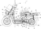
图1是具有本发明的第一实施方式的电动车辆用充电装置的电动车辆的左视图。FIG. 1 is a left side view of an electric vehicle having a charging device for an electric vehicle according to a first embodiment of the present invention.
图2是本发明的第一实施方式的充电连接器的俯视图。Fig. 2 is a plan view of the charging connector according to the first embodiment of the present invention.
图3是充电连接器的左视图。Fig. 3 is a left side view of the charging connector.
图4是表示充电连接器的锁定杆的动作的示意图。FIG. 4 is a schematic diagram showing the operation of a lock lever of the charging connector.
图5是表示充电连接器的锁定杆的动作的示意图。Fig. 5 is a schematic diagram showing the operation of a lock lever of the charging connector.
图6是表示相对于车辆侧的钩部件进行的锁定杆的动作的主要部分放大图。6 is an enlarged view of a main part showing the operation of the lock lever with respect to the hook member on the vehicle side.
图7是表示充电控制装置的结构的框图。FIG. 7 is a block diagram showing the configuration of a charging control device.
图8是表示控制部的主要部分功能的框图。FIG. 8 is a block diagram showing the main functions of the control unit.
图9是表示充电装置的状态与显示机构的显示之间的关系的图。9 is a diagram showing the relationship between the state of the charging device and the display of the display means.
附图标记说明Explanation of reference signs
1 电动车辆,1 electric vehicle,
4 主电池,4 main batteries,
8 充电耦合器主体,8 Charge coupler body,
10 手柄,10 handles,
12 操作杆,12 joystick,
14 充电开始开关,14 Charging start switch,
16 锁定杆,16 locking lever,
18 电机,18 motors,
23 连杆,23 connecting rods,
30 钩部件,30 hook parts,
43 充电连接器,43 charging connector,
44 充电口,44 charging port,
49 LED,49 LEDs,
52 电子蜂鸣器,52 electronic buzzer,
60 充电器,60 charger,
62 充电耦合器,62 charging coupler,
64 PFC电路,64 PFC circuits,
65 控制部。65 Department of Control.
具体实施方式Detailed ways
以下,参照附图对本发明的第一实施方式进行说明。图1是具有本发明的第一实施方式的电动车辆用充电装置的电动车辆的左视图。电动车辆1是具有低床式底板的踏板型两轮电动车。车身架3由头管31、前端与头管31接合且后端向下方延伸的前车架部分32、从前车架部分32向车身宽度方向的左右分别分支并向车身靠后方延伸的一对主车架部分33、和从主车架部分33向车身后上方延伸的后车架部分36而构成。Hereinafter, a first embodiment of the present invention will be described with reference to the drawings. FIG. 1 is a left side view of an electric vehicle having a charging device for an electric vehicle according to a first embodiment of the present invention. The electric vehicle 1 is a scooter-type two-wheeled electric vehicle having a low-bed floor. The
在头管31上以自由转向的方式支承有对前轮WF进行支承的前叉2。在从前叉2向上部延伸且由头管31支承的转向轴41的上部,连结有具有加速手柄的转向把手46。The
在头管31的前部结合有托架37,在该托架37的前端部上安装有头灯25,并在头灯25的上方设置有由托架37支承的前承载架26。A
在主车架部分33与后车架部分36的中间区域内接合有朝向车身后方延伸的托架34,在托架34上设置有在车身宽度方向上延伸的枢轴35。枢轴35以上下自由摆动的方式将摆臂17支承,该摆臂17具有作为车辆驱动源的电机18和后轮车轴19。电机18的输出传递给后轮车轴19,从而驱动由后轮车轴19支承的后轮WR。将后轮车轴19支承的外壳的后端与后车架部分36通过后减震器20而连结。A bracket 34 extending toward the rear of the vehicle body is joined to an intermediate region between the
在托架34上设置有停车时支承车身的侧支架24,侧支架24具有当侧支架24收容在规定位置上时输出检测信号的侧支架开关28。The side stand 24 that supports the vehicle body during parking is provided on the bracket 34, and the side stand 24 has a
在主车架部分33上搭载有由多个蓄电池组构成的高电压(例如额定72伏)的主电池4,主电池4的上部由盖40覆盖。在主电池4的前部连结有空气导入管38,在主电池4的后部设置有进气风扇39。通过进气风扇39从空气导入管38向主电池4导入空气,所导入的空气将主电池4冷却,之后向车身后方排出。空气从未图示的空气滤清器通过而导入到空气导入管38中。A high-voltage (for example, 72-volt rated)
在后车架部分36之上设置有充电口44,该充电口44能够将对主电池4进行充电的从车外的充电器延伸出的充电线缆42的充电连接器43结合。在后车架部分36上设置有后承载架29和尾灯27。On the
在左右一对的后车架部分36之间设置有行李箱50,在从行李箱50向下部突出的行李箱底部51中收容有通过主电池4充电的低电压(例如额定12伏)的副电池5。在摆臂17上设置有对电机18进行控制的动力驱动单元(PDU、Power Drive Unit)45。A
在行李箱50之上设置有兼用作行李箱50的盖的驾驶员座椅21,在驾驶员座椅21上设置有当驾驶员落座时工作而输出落座信号的座椅开关22。A driver's
图2是表示本实施方式的充电装置的主要部分即充电连接器的外观的俯视图,图3是其侧视图。充电连接器43具有连接器主体8、从连接器主体8延伸的把手10、和由枢轴11枢轴支承在连接器主体8上并与把手10大致平行延伸的操作杆12。操作杆12通过设置在枢轴11周围的弹簧13而向从把手10远离的方向(后述的“锁定位置”的方向)弹压。FIG. 2 is a plan view showing the appearance of a charging connector which is a main part of the charging device according to the present embodiment, and FIG. 3 is a side view thereof. The charging
在连接器主体10的上部,设置有充电开始开关14及显示机构15。充电开始开关14也可以作为充电开始/停止开关而构成。也就是说,能够以若在充电中操作该开关14,则使充电被停止的方式构成。图2中,充电开始开关14表示其外观即操作按钮141,与操作按钮141的按下及复位对应地将接点开闭的开关主体142配置在操作按钮141的下方。On the upper portion of the connector
在连接器主体8内设置有由枢轴55枢轴支承并能够在上下方向上摆动的锁定杆16,锁定杆16及操作杆12使用连结轴47、48而由连杆23连结。锁定杆16的前端部16a以能够与设于充电口44上的钩型部件(钩部件)30卡定的方式形成为钩型。Inside the connector
另外,在连接器主体8的上部,以与充电开始开关14邻接的方式设有作为指示灯的LED49。指示灯用于显示充电状态、和充电连接器43与充电口44的电连接状态,除了基于LED49发出的光而进行显示之外,为了基于声音而进行显示,也能够设置电子蜂鸣器52。充电开始开关14、LED49、以及电子蜂鸣器52安装在基板53上。从充电开始开关14引出的信号线和用于向LED49及电子蜂鸣器52供电的电线与充电用电线54一起被包覆,而作为线束56延伸至未图示的充电器。在操作按钮141与基板53之间设置有复位弹簧57,该复位弹簧57作用于将操作按钮141推起的方向上。In addition, an
接着,参照图4及图5说明充电连接器43与充电口44的连接动作,并且说明操作杆12和锁定杆16的动作。图4表示解锁位置上的各部件的位置,图5是解锁位置与锁定位置的中间位置上的主要部分放大图,图6是表示锁定位置上的各部件的位置的示意图。操作杆12通过弹簧13在枢轴11的周围,如图4中箭头A所示地沿顺时针方向弹压。操作杆12从枢轴11朝向前端、即朝向连接器主体8的前端部(图中左侧)延伸,在该延伸部上,连杆23的一端(下端)通过连结轴48与操作杆12连结。另一方面,锁定杆16从枢轴55朝向前端、即朝向图中右侧延伸,在该延伸部16b上通过连结轴49连结有连杆23的另一端(上端)。锁定杆16的延伸部16b延伸到操作按钮141的下缘的下方。Next, the connection operation of the charging
根据该结构,在图4的状态下,由于操作杆12被弹簧13弹压,所以与操作杆12连结的连杆23如箭头B所示地向上方位移。于是,锁定杆16的延伸部16b追随连杆23的位移而向上方被推起,使锁定杆16在枢轴55的周围沿逆时针方向旋转。由此,锁定杆16的前端部16a向下方位移,而与充电连接器43的位于锁定杆16的前端部16a的下方的、引导筒431的外周面抵接。另一方面,锁定杆16的延伸部16b以枢轴55为中心沿逆时针方向旋转,并位移至操作按钮141的边缘的正下方。因此,锁定杆16处于该图4的位置而对操作按钮141的工作范围进行干涉,使得将按下操作按钮141向箭头C的方向按下的动作被阻止。在图4的解锁状态下,由于操作杆12处于沿顺时针方向旋转后的位置上,所以操作杆12与把手10的间隔SP变宽,具有难以同时握住操作杆12和把手10的位置关系,难以进行误操作。因此,能够防止在将充电连接器43从充电口44卸下时对操作杆12进行操作,而使充电开始开关14变得能够工作。According to this configuration, in the state of FIG. 4 , since the operating
为了将充电连接器43连接在充电口44上而将其按入至充电口44中时,如图6所示,成为倾斜面的钩部件30的前端上部30a与锁定杆16的前端部16a的上部倾斜面16c抵接,并将锁定杆16推起。When the charging
而且,若将充电连接器43进一步向充电口44侧按入,则如图6所示,锁定杆16的前端部16a从图中右侧向左侧越过钩部件30的前端上部30a,使前端形成为钩形的锁定杆16以及钩部件30彼此之间相互卡合,从而以使充电连接器43维持锁定状态的方式相对于充电口44连接。Moreover, if the charging
在钩部件30与锁定杆16的前端部16a卡合的锁定位置上,与解锁位置相比,锁定杆16以枢轴55为中心沿顺时针方向旋转,如图5所示,锁定杆16的延伸部16b从操作按钮141的正下方离开,并下降到不对操作按钮141的工作范围进行干涉的位置。其结果是,按下操作按钮141而能够进行充电开始操作。在图5所示的位置上,锁定杆16旋转而使连杆23沿着箭头D的方向下降,因此,操作杆12以枢轴11为中心沿逆时针方向(箭头E的方向)旋转而向把手10侧靠近,由此,间隔SP变小。At the locked position where the
在充电连接器43和充电口44上分别设置有供电线用端子和信号线用端子,在锁定杆16的前端部16a越过钩部件30的前端上部30a而卡合的位置上,供电线用端子和信号线用端子均被连接,能够在充电器以及车身侧的充电控制装置之间进行供电以及信号的发送接收。The charging
当将充电连接器43从充电口44上卸下的情况下,使操作杆12拉至把手10侧。在锁定位置上,由于操作杆12已经靠近至把手10侧,所以能够轻松地进行以将操作杆12和把手10同时握持的方式使操作杆12向把手10接近的操作。When detaching the charging
通过使操作杆12向把手10拉近的操作,连杆23向下方位移,锁定杆16以枢轴55为中心沿顺时针方向旋转,且前端部16a与钩部件30的前端上部30a相比向上方抬起,因此,锁定被解除,并能够将充电连接器43从充电口44上拔出而卸下。在将充电连接器43从充电口44上卸下之后,若手从操作杆12上松开,则基于弹簧13的作用而使连杆23抬起,锁定杆16的延伸部16b也再次返回到对操作按钮141的工作范围进行干涉的位置上。When the
接着,对包括充电连接器的充电控制装置进行说明。图7是表示充电控制装置的结构的框图。构成充电控制装置的充电器60与电动车辆1侧的电力供给装置61通过由充电连接器43及充电口44构成的充电耦合器62而连接。电力供给装置61通过PDU45来控制向电机18供给的电力,并且具有用于对蓄电池4进行充电的电路。充电器60与电力供给装置61从充电耦合器62通过而由电线PL1、PL2和信号线SL1连接。Next, a charging control device including a charging connector will be described. FIG. 7 is a block diagram showing the configuration of a charging control device. A
充电器60具有整流器63、PFC电路64、和控制部65。整流器63具有滤波电路及整流电路,将从AC插头66通过而输入的来自商用交流电力系统的电压整流成直流电。PFC电路64是对从整流器63输入的直流电进行升压,并将其供给至车辆侧的电力供给装置61的输出电路。The
具有微型计算机的控制部65始终监视PFC电路64的输出电压,并进行恒压控制以使其不超过设定电压(例如400伏)。在控制部65上连接有充电开始开关14。另外,控制部65具有充电开始/停止功能,该充电开始/停止功能为,基于表示充电耦合器62已连接的连接检测信号而开始充电,或者根据从车辆侧通过信号线SL1而发送的充电停止信号而停止充电。在本实施方式中,以使充电连接器43插入至充电口44中而使充电耦合器62被连接的方式锁定,且在识别到连接检测信号,而且充电开始开关14被开启操作的状态下开始无电。The
电力供给装置61包括具有电池管理单元(BMU)4a的主电池4、PDU45、第一DC/DC转换器68、和第二DC/DC转换器69。第一DC/DC转换器68将输入电压(在此为400伏)降压成蓄电池4的充电电压(72伏)并输出。第一DC/DC转换器68的输出侧与蓄电池4及第二DC/DC转换器69连接。第二DC/DC转换器69将从第一DC/DC转换器68输出的72伏的直流电降压成能够作为PDU45等控制电源用而使用的低电压(例如,直流12伏)。The
PDU45具有微型计算机,在其与BMU4a之间进行通信(例如CAN通信),发送和接收蓄电池4的充电状态(过充电信息等)和与此对应的蓄电池4的控制信息。此外,PDU45与充电器60的控制部65通过信号线SL1连接。蓄电池4的直流输出电压通过设置在PDU45上的未图示的变换器电路而转换成三相交流电压,并向车辆驱动源即电机18(参照图1)输入。在设置在蓄电池4上的BMU4a与第一DC/DC转换器68之间设置有接触器70。The
图8是表示包括对充电器60与电力供给装置61已连接的情况进行检测的连接检测部在内的充电控制装置的主要部分功能的框图。在图8中,在PFC电路64的输出端子(充电器60的输出端子)上经由限流电阻R1施加有识别电压,并通过连接检测部71监视施加在该输出端子上的识别电压。当连接了充电耦合器62时,电流会流入至电力供给装置61内的第一DC/DC转换器68中,因此,识别电压会降低。连接检测部71检测该电压降低而识别到充电耦合器62已被连接。FIG. 8 is a block diagram showing the main functions of the charging control device including a connection detection unit that detects that the
在车辆侧的电力供给装置61中,信号线SL1经由晶体管Tr与电线PL1连接,当结束充电时,PDU45打开该晶体管Tr。控制部65的充电停止检测部72监视信号线SL1的电位,当根据从PDU45输入的充电停止信号而打开晶体管Tr时,信号线SL1的电压变化为规定值。充电停止检测部72检测信号线SL1的该电压变化而识别到充电停止信号的输入,从而使来自PFC电路64的输出停止。In the
这样,根据本实施方式的充电控制装置,充电器60能够根据施加在充电耦合器62上的识别信号的降低,来检测充电耦合器62的充电连接器43与充电口44有无连接,从而开始充电。另外,由于充电器60的PFC电路64输出恒压直至其输出界限,所以PDU45能够使充电电流增加直至来自充电器60的输出电压降低。因此,充电器60能够以最大输出向蓄电池4供给充电电流。In this way, according to the charging control device of this embodiment, the
根据图7及图8中所说明的充电控制装置的动作,通过作为显示机构的LED49及电子蜂鸣器52使状态被显示。图9是表示充电装置的状态与显示机构的显示之间的关系的图。显示机构的驱动功能能够作为控制部65的功能来实现。如图9所示,当由连接检测部71检测出充电耦合器62的连接时,由电子蜂鸣器52进行一次时间t1(例如0.2秒)的发声,并且使LED49以规定的周期T(例如1赫兹)闪烁。另外,当PFC电路64动作并开始充电时,由电子蜂鸣器52进行两次时间t1的发声,并且使LED49连续闪烁。进一步地,当充电在完全充满之前停止时,使电子蜂鸣器52进行三次比时间t1长的时间t2(例如1.0秒)的发声,并使LED49熄灭。而且,在充电完成后,实施一次时间t2的发声。在断开充电耦合器62后,电子蜂鸣器52不发声,且LED49不亮灯也不闪烁。Based on the operation of the charging control device described in FIGS. 7 and 8 , the status is displayed by the
通过显示机构也能显示异常动作(故障)。例如,当检测出故障时,进行三次时间t2的发声,并使LED49以周期T闪烁。例如,当通过连接检测部71检测出与规定电压不同的电压,或者完全检测不出电压的情况下,判断为故障。此外,显示机构的显示方式并不限定于此,也可以仅通过LED49及电子蜂鸣器52中的任意一方来进行显示。Abnormal operation (failure) can also be displayed through the display mechanism. For example, when a failure is detected, sounding is performed three times for time t2, and
另外,在本实施方式中,虽然锁定杆16的延伸部16b和连杆23的上部对操作按钮141的工作范围进行干涉而将操作按钮141的操作限制,但本发明并不限定于此。主要在于,只要以如下的方式配置充电开始开关14和可动部即可,该方式为,当操作杆12处于图4所示的位置上时,包括锁定杆16、连杆23以及操作杆12在内的可动部的一部分处于对操作按钮141的工作范围进行干涉的位置上,在拉动操作杆12而操作成图5的状态(锁定位置)后,处于所述干扰位置上的可动部的一部分从操作按钮141的工作范围向工作范围外移动。In addition, in this embodiment, although the
另外,将操作杆12和锁定杆16连结的连结机构并不限于连杆23,也可以使用凸轮机构和齿轮机构来连结操作杆12和锁定杆16。In addition, the connecting mechanism connecting the
Claims (8)
Translated fromChineseApplications Claiming Priority (2)
| Application Number | Priority Date | Filing Date | Title |
|---|---|---|---|
| JP2012071276AJP5912740B2 (en) | 2012-03-27 | 2012-03-27 | Charging device for electric vehicle |
| JP2012-071276 | 2012-03-27 |
Publications (2)
| Publication Number | Publication Date |
|---|---|
| CN103358928Atrue CN103358928A (en) | 2013-10-23 |
| CN103358928B CN103358928B (en) | 2016-04-13 |
Family
ID=47997090
Family Applications (1)
| Application Number | Title | Priority Date | Filing Date |
|---|---|---|---|
| CN201310118519.5AActiveCN103358928B (en) | 2012-03-27 | 2013-03-22 | Electric vehicles charging unit |
Country Status (5)
| Country | Link |
|---|---|
| US (1) | US8932072B2 (en) |
| EP (1) | EP2644442B1 (en) |
| JP (1) | JP5912740B2 (en) |
| CN (1) | CN103358928B (en) |
| ES (1) | ES2727081T3 (en) |
Cited By (7)
| Publication number | Priority date | Publication date | Assignee | Title |
|---|---|---|---|---|
| CN105679573A (en)* | 2016-04-07 | 2016-06-15 | 深圳易瓦科技有限公司 | Charging device locking mechanism, installation method and locking/unlocking method |
| CN107444146A (en)* | 2016-05-31 | 2017-12-08 | 泰连德国有限公司 | Actuator module for the entrance that charges |
| CN108099676A (en)* | 2018-01-08 | 2018-06-01 | 严华松 | A kind of new energy mobile charging rifle and its charge control method |
| CN108394309A (en)* | 2018-06-06 | 2018-08-14 | 深圳草莓创新技术有限公司 | A kind of unmanned machine battery positioning and locking device and its method |
| CN109311406A (en)* | 2016-06-17 | 2019-02-05 | 山特维克矿山工程机械有限公司 | Electric device charging connector arrangement in ground vehicle |
| CN111446810A (en)* | 2020-04-03 | 2020-07-24 | 广东博智林机器人有限公司 | Battery taking and placing device and battery replacing equipment |
| CN114844183A (en)* | 2021-02-01 | 2022-08-02 | 丰田自动车株式会社 | Portable charger |
Families Citing this family (32)
| Publication number | Priority date | Publication date | Assignee | Title |
|---|---|---|---|---|
| JP5798935B2 (en)* | 2012-01-17 | 2015-10-21 | 矢崎総業株式会社 | Electrical connector |
| JP5912740B2 (en)* | 2012-03-27 | 2016-04-27 | 本田技研工業株式会社 | Charging device for electric vehicle |
| JP5912758B2 (en)* | 2012-03-29 | 2016-04-27 | 本田技研工業株式会社 | Electric vehicle charging control device |
| JP5939927B2 (en)* | 2012-08-06 | 2016-06-22 | 矢崎総業株式会社 | Charging connector |
| JP5902602B2 (en)* | 2012-12-13 | 2016-04-13 | 株式会社東海理化電機製作所 | Locking device |
| JP5945067B2 (en)* | 2013-03-28 | 2016-07-05 | 矢崎総業株式会社 | Charging connector |
| IN2014DE03073A (en)* | 2013-11-05 | 2015-07-10 | Suzuki Motor Corp | |
| JP6303188B2 (en)* | 2014-03-24 | 2018-04-04 | 三菱自動車工業株式会社 | Electric vehicle charging device |
| JP2016002896A (en) | 2014-06-17 | 2016-01-12 | ヤマハ発動機株式会社 | Saddle-riding type electric vehicle |
| US10179518B2 (en) | 2014-11-14 | 2019-01-15 | Ricky Jay Henderson | Power docking port system with tetrahedral charging probe |
| JP6009528B2 (en)* | 2014-12-18 | 2016-10-19 | 住友電装株式会社 | Charging inlet |
| DE102015113875A1 (en)* | 2015-08-21 | 2017-02-23 | Phoenix Contact E-Mobility Gmbh | Connector part with a locking element |
| JP2018110472A (en)* | 2016-12-28 | 2018-07-12 | 三菱電機株式会社 | Charging / discharging system, power conditioner and cable |
| JP2018153033A (en)* | 2017-03-14 | 2018-09-27 | 株式会社椿本チエイン | Charge and discharge device |
| DE102017109988B4 (en)* | 2017-05-09 | 2019-08-01 | Conductix-Wampfler Gmbh | Power supply system and method for connecting a cable to a connection device |
| JP6496356B2 (en)* | 2017-05-30 | 2019-04-03 | 本田技研工業株式会社 | vehicle |
| US10348038B2 (en) | 2017-07-21 | 2019-07-09 | Ford Global Technologies, Llc | Soft lock to secure an EVSE-to-EV charging connector |
| DE102017119056B4 (en)* | 2017-08-21 | 2022-05-19 | HARTING Automotive GmbH | Charging connector with actuation means |
| US10453282B2 (en) | 2017-08-22 | 2019-10-22 | Ford Global Technologies, Llc | EV charging connector unlock via biometric input |
| AT520422A2 (en)* | 2017-08-28 | 2019-03-15 | Mechanical lock for charging plug | |
| JP6840104B2 (en)* | 2018-04-18 | 2021-03-10 | 本田技研工業株式会社 | Battery charger |
| US10790628B2 (en) | 2018-05-18 | 2020-09-29 | Nvidia Corporation | Electronically actuated retaining latch for AC-DC adapter removable plug assembly |
| DE102018131610A1 (en)* | 2018-12-10 | 2020-06-10 | Phoenix Contact E-Mobility Gmbh | Charging plug with a detent connection detection |
| US11067616B2 (en)* | 2019-05-17 | 2021-07-20 | Shimano Inc. | Connecting-state detection system |
| US11964584B2 (en)* | 2020-09-16 | 2024-04-23 | Apple Inc. | Accessory power pack |
| CN112849315B (en)* | 2020-11-10 | 2022-08-16 | 浙江春风动力股份有限公司 | Electric motorcycle with stable structure |
| CN114552277A (en)* | 2020-11-24 | 2022-05-27 | 台达电子工业股份有限公司 | charging gun |
| CN114142305B (en)* | 2021-08-24 | 2023-05-12 | 深圳市德兰明海科技有限公司 | Connector and electronic equipment |
| CN114572028B (en)* | 2022-03-16 | 2023-11-10 | 深圳市广和通科技有限公司 | Charging control device and charging control method |
| CN115441267B (en)* | 2022-08-09 | 2025-07-08 | 始途科技(杭州)有限公司 | Flexible adjustable charging gun, charging butt joint structure and charging control method |
| US20240083269A1 (en)* | 2022-09-14 | 2024-03-14 | Rivian Ip Holdings, Llc | Charge coupler |
| KR102698311B1 (en)* | 2022-11-30 | 2024-08-26 | 현대모비스 주식회사 | Charging gun disconnecting apparatus |
Citations (5)
| Publication number | Priority date | Publication date | Assignee | Title |
|---|---|---|---|---|
| US5350312A (en)* | 1992-12-18 | 1994-09-27 | Yazaka Corporation | Feeder connector |
| US5573417A (en)* | 1992-12-18 | 1996-11-12 | Yazaki Corporation | Feeding connector |
| US5803760A (en)* | 1994-08-08 | 1998-09-08 | Sumitomo Wiring Systems, Ltd. | Releasable connector |
| CN101188319A (en)* | 2006-11-16 | 2008-05-28 | 比亚迪股份有限公司 | A charging device for an electric vehicle |
| CN102017320A (en)* | 2008-11-21 | 2011-04-13 | 矢崎总业株式会社 | Charging connector |
Family Cites Families (16)
| Publication number | Priority date | Publication date | Assignee | Title |
|---|---|---|---|---|
| US5491418A (en)* | 1994-10-27 | 1996-02-13 | General Motors Corporation | Automotive diagnostic communications interface |
| JP3135040B2 (en)* | 1995-11-30 | 2001-02-13 | 矢崎総業株式会社 | Electric vehicle charging connector |
| US6371768B1 (en)* | 1998-03-31 | 2002-04-16 | Daimlerchrysler Corporation | Universal charge port connector for electric vehicles |
| US6225153B1 (en)* | 1999-03-24 | 2001-05-01 | Daimlerchrysler Corporation | Universal charge port connector for electric vehicles |
| US7963793B2 (en)* | 2009-09-24 | 2011-06-21 | Lear Corporation | Hybrid/electric vehicle charge handle latch mechanism |
| US8016607B2 (en)* | 2010-01-08 | 2011-09-13 | Lear Corporation | Connector assembly for electric vehicle charging |
| JP5392151B2 (en)* | 2010-03-09 | 2014-01-22 | 住友電装株式会社 | Charging connector |
| JP5482295B2 (en)* | 2010-03-01 | 2014-05-07 | 住友電装株式会社 | Charging connector |
| JP2011223669A (en)* | 2010-04-06 | 2011-11-04 | On Semiconductor Trading Ltd | Charger for portable electronic apparatus |
| JP5520699B2 (en)* | 2010-06-08 | 2014-06-11 | 株式会社東海理化電機製作所 | Locking device |
| US7878866B1 (en)* | 2010-07-02 | 2011-02-01 | Lear Corporation | Connector assembly for vehicle charging |
| JP5491328B2 (en)* | 2010-09-01 | 2014-05-14 | 株式会社東海理化電機製作所 | Plug lock structure |
| JP5890091B2 (en)* | 2010-10-29 | 2016-03-22 | 日本航空電子工業株式会社 | Electric connector, electric connector unit, and charger for electric vehicle |
| US20120126747A1 (en)* | 2010-11-19 | 2012-05-24 | Delphi Technologies, Inc. | Battery charger having non-contact electrical switch |
| JP2012206577A (en)* | 2011-03-29 | 2012-10-25 | Tokai Rika Co Ltd | Power plug locking device |
| JP5912740B2 (en)* | 2012-03-27 | 2016-04-27 | 本田技研工業株式会社 | Charging device for electric vehicle |
- 2012
- 2012-03-27JPJP2012071276Apatent/JP5912740B2/enactiveActive
- 2013
- 2013-03-14USUS13/804,293patent/US8932072B2/enactiveActive
- 2013-03-21EPEP13160345.8Apatent/EP2644442B1/enactiveActive
- 2013-03-21ESES13160345Tpatent/ES2727081T3/enactiveActive
- 2013-03-22CNCN201310118519.5Apatent/CN103358928B/enactiveActive
Patent Citations (5)
| Publication number | Priority date | Publication date | Assignee | Title |
|---|---|---|---|---|
| US5350312A (en)* | 1992-12-18 | 1994-09-27 | Yazaka Corporation | Feeder connector |
| US5573417A (en)* | 1992-12-18 | 1996-11-12 | Yazaki Corporation | Feeding connector |
| US5803760A (en)* | 1994-08-08 | 1998-09-08 | Sumitomo Wiring Systems, Ltd. | Releasable connector |
| CN101188319A (en)* | 2006-11-16 | 2008-05-28 | 比亚迪股份有限公司 | A charging device for an electric vehicle |
| CN102017320A (en)* | 2008-11-21 | 2011-04-13 | 矢崎总业株式会社 | Charging connector |
Cited By (10)
| Publication number | Priority date | Publication date | Assignee | Title |
|---|---|---|---|---|
| CN105679573A (en)* | 2016-04-07 | 2016-06-15 | 深圳易瓦科技有限公司 | Charging device locking mechanism, installation method and locking/unlocking method |
| CN107444146A (en)* | 2016-05-31 | 2017-12-08 | 泰连德国有限公司 | Actuator module for the entrance that charges |
| CN107444146B (en)* | 2016-05-31 | 2022-07-01 | 泰连德国有限公司 | Actuator module for charging inlet |
| CN109311406A (en)* | 2016-06-17 | 2019-02-05 | 山特维克矿山工程机械有限公司 | Electric device charging connector arrangement in ground vehicle |
| CN109311406B (en)* | 2016-06-17 | 2022-02-15 | 山特维克矿山工程机械有限公司 | Charging connector arrangement in underground vehicle |
| CN108099676A (en)* | 2018-01-08 | 2018-06-01 | 严华松 | A kind of new energy mobile charging rifle and its charge control method |
| CN108394309A (en)* | 2018-06-06 | 2018-08-14 | 深圳草莓创新技术有限公司 | A kind of unmanned machine battery positioning and locking device and its method |
| CN111446810A (en)* | 2020-04-03 | 2020-07-24 | 广东博智林机器人有限公司 | Battery taking and placing device and battery replacing equipment |
| CN111446810B (en)* | 2020-04-03 | 2022-05-17 | 广东博智林机器人有限公司 | Battery taking and placing device and battery replacing equipment |
| CN114844183A (en)* | 2021-02-01 | 2022-08-02 | 丰田自动车株式会社 | Portable charger |
Also Published As
| Publication number | Publication date |
|---|---|
| ES2727081T3 (en) | 2019-10-14 |
| EP2644442A3 (en) | 2014-05-07 |
| US20130260595A1 (en) | 2013-10-03 |
| JP5912740B2 (en) | 2016-04-27 |
| EP2644442A2 (en) | 2013-10-02 |
| JP2013207829A (en) | 2013-10-07 |
| US8932072B2 (en) | 2015-01-13 |
| CN103358928B (en) | 2016-04-13 |
| EP2644442B1 (en) | 2019-04-24 |
Similar Documents
| Publication | Publication Date | Title |
|---|---|---|
| CN103358928B (en) | Electric vehicles charging unit | |
| CN103250320B (en) | The battery charge controller of motor vehicle | |
| US8653788B2 (en) | Charging cable and charging system for electrically powered vehicle | |
| JP5438223B2 (en) | Open / close detection device for charging lid | |
| CN102414936B (en) | Charging connector and charging cable unit | |
| CN102790317B (en) | Connector keeps equipment and uses the charging device of this equipment | |
| CN105144540B (en) | Vehicle-mounted charging device | |
| US11420698B2 (en) | Saddle type electric vehicle | |
| JP5197563B2 (en) | Straddle-type electric vehicle | |
| US20160137149A1 (en) | Power supply device for auxiliary device battery | |
| CN102315666A (en) | Discharge Control Devices in Electric Vehicles | |
| CN104169122A (en) | Charging-port control device for electric vehicle | |
| JP2011010420A (en) | Charging system of electric vehicle and charge control device of electric vehicle | |
| TWI419423B (en) | Charging device | |
| WO2013111311A1 (en) | On-board charging and communication device and vehicle charging and communication system | |
| EP2644441A2 (en) | Charging control device for electrically driven vehicle | |
| WO2013034966A1 (en) | Charging apparatus for electric motor vehicles | |
| CN103718423B (en) | Electric vehicles charging device | |
| JP5900744B2 (en) | Vehicle power supply system | |
| US20200282850A1 (en) | Saddle type electric vehicle | |
| JP2013090422A (en) | Charging system, power supply side connecting member, and vehicle side connecting member | |
| CN104010933B (en) | straddle-type electric vehicle | |
| CN104024097A (en) | Saddle-type electric vehicle | |
| JP5829922B2 (en) | On-vehicle charging device and vehicle charging system | |
| JP2013074719A (en) | Portable power supply device |
Legal Events
| Date | Code | Title | Description |
|---|---|---|---|
| C06 | Publication | ||
| PB01 | Publication | ||
| C10 | Entry into substantive examination | ||
| SE01 | Entry into force of request for substantive examination | ||
| C14 | Grant of patent or utility model | ||
| GR01 | Patent grant |