CN103354901A - Biological sample measuring device - Google Patents
Biological sample measuring deviceDownload PDFInfo
- Publication number
- CN103354901A CN103354901ACN2012800067797ACN201280006779ACN103354901ACN 103354901 ACN103354901 ACN 103354901ACN 2012800067797 ACN2012800067797 ACN 2012800067797ACN 201280006779 ACN201280006779 ACN 201280006779ACN 103354901 ACN103354901 ACN 103354901A
- Authority
- CN
- China
- Prior art keywords
- sensor
- biological sample
- measurement
- unit
- acceleration
- Prior art date
- Legal status (The legal status is an assumption and is not a legal conclusion. Google has not performed a legal analysis and makes no representation as to the accuracy of the status listed.)
- Granted
Links
Images


Classifications
- G—PHYSICS
- G01—MEASURING; TESTING
- G01N—INVESTIGATING OR ANALYSING MATERIALS BY DETERMINING THEIR CHEMICAL OR PHYSICAL PROPERTIES
- G01N27/00—Investigating or analysing materials by the use of electric, electrochemical, or magnetic means
- G01N27/26—Investigating or analysing materials by the use of electric, electrochemical, or magnetic means by investigating electrochemical variables; by using electrolysis or electrophoresis
- G01N27/28—Electrolytic cell components
- G01N27/30—Electrodes, e.g. test electrodes; Half-cells
- G01N27/327—Biochemical electrodes, e.g. electrical or mechanical details for in vitro measurements
- A—HUMAN NECESSITIES
- A61—MEDICAL OR VETERINARY SCIENCE; HYGIENE
- A61B—DIAGNOSIS; SURGERY; IDENTIFICATION
- A61B5/00—Measuring for diagnostic purposes; Identification of persons
- A61B5/145—Measuring characteristics of blood in vivo, e.g. gas concentration or pH-value ; Measuring characteristics of body fluids or tissues, e.g. interstitial fluid or cerebral tissue
- A61B5/14532—Measuring characteristics of blood in vivo, e.g. gas concentration or pH-value ; Measuring characteristics of body fluids or tissues, e.g. interstitial fluid or cerebral tissue for measuring glucose, e.g. by tissue impedance measurement
- A—HUMAN NECESSITIES
- A61—MEDICAL OR VETERINARY SCIENCE; HYGIENE
- A61B—DIAGNOSIS; SURGERY; IDENTIFICATION
- A61B5/00—Measuring for diagnostic purposes; Identification of persons
- A61B5/15—Devices for taking samples of blood
- A61B5/150007—Details
- A61B5/150015—Source of blood
- A61B5/150022—Source of blood for capillary blood or interstitial fluid
- A—HUMAN NECESSITIES
- A61—MEDICAL OR VETERINARY SCIENCE; HYGIENE
- A61B—DIAGNOSIS; SURGERY; IDENTIFICATION
- A61B5/00—Measuring for diagnostic purposes; Identification of persons
- A61B5/15—Devices for taking samples of blood
- A61B5/150007—Details
- A61B5/150358—Strips for collecting blood, e.g. absorbent
- A—HUMAN NECESSITIES
- A61—MEDICAL OR VETERINARY SCIENCE; HYGIENE
- A61B—DIAGNOSIS; SURGERY; IDENTIFICATION
- A61B5/00—Measuring for diagnostic purposes; Identification of persons
- A61B5/15—Devices for taking samples of blood
- A61B5/151—Devices specially adapted for taking samples of capillary blood, e.g. by lancets, needles or blades
- A61B5/15101—Details
- A61B5/15126—Means for controlling the lancing movement, e.g. 2D- or 3D-shaped elements, tooth-shaped elements or sliding guides
- A—HUMAN NECESSITIES
- A61—MEDICAL OR VETERINARY SCIENCE; HYGIENE
- A61B—DIAGNOSIS; SURGERY; IDENTIFICATION
- A61B5/00—Measuring for diagnostic purposes; Identification of persons
- A61B5/15—Devices for taking samples of blood
- A61B5/157—Devices characterised by integrated means for measuring characteristics of blood
- G—PHYSICS
- G01—MEASURING; TESTING
- G01N—INVESTIGATING OR ANALYSING MATERIALS BY DETERMINING THEIR CHEMICAL OR PHYSICAL PROPERTIES
- G01N33/00—Investigating or analysing materials by specific methods not covered by groups G01N1/00 - G01N31/00
- G01N33/48—Biological material, e.g. blood, urine; Haemocytometers
- G01N33/483—Physical analysis of biological material
- G01N33/487—Physical analysis of biological material of liquid biological material
- G01N33/4875—Details of handling test elements, e.g. dispensing or storage, not specific to a particular test method
- C—CHEMISTRY; METALLURGY
- C12—BIOCHEMISTRY; BEER; SPIRITS; WINE; VINEGAR; MICROBIOLOGY; ENZYMOLOGY; MUTATION OR GENETIC ENGINEERING
- C12Q—MEASURING OR TESTING PROCESSES INVOLVING ENZYMES, NUCLEIC ACIDS OR MICROORGANISMS; COMPOSITIONS OR TEST PAPERS THEREFOR; PROCESSES OF PREPARING SUCH COMPOSITIONS; CONDITION-RESPONSIVE CONTROL IN MICROBIOLOGICAL OR ENZYMOLOGICAL PROCESSES
- C12Q1/00—Measuring or testing processes involving enzymes, nucleic acids or microorganisms; Compositions therefor; Processes of preparing such compositions
- C12Q1/001—Enzyme electrodes
- C12Q1/005—Enzyme electrodes involving specific analytes or enzymes
- C12Q1/006—Enzyme electrodes involving specific analytes or enzymes for glucose
- C—CHEMISTRY; METALLURGY
- C12—BIOCHEMISTRY; BEER; SPIRITS; WINE; VINEGAR; MICROBIOLOGY; ENZYMOLOGY; MUTATION OR GENETIC ENGINEERING
- C12Q—MEASURING OR TESTING PROCESSES INVOLVING ENZYMES, NUCLEIC ACIDS OR MICROORGANISMS; COMPOSITIONS OR TEST PAPERS THEREFOR; PROCESSES OF PREPARING SUCH COMPOSITIONS; CONDITION-RESPONSIVE CONTROL IN MICROBIOLOGICAL OR ENZYMOLOGICAL PROCESSES
- C12Q1/00—Measuring or testing processes involving enzymes, nucleic acids or microorganisms; Compositions therefor; Processes of preparing such compositions
- C12Q1/54—Measuring or testing processes involving enzymes, nucleic acids or microorganisms; Compositions therefor; Processes of preparing such compositions involving glucose or galactose
- G—PHYSICS
- G01—MEASURING; TESTING
- G01N—INVESTIGATING OR ANALYSING MATERIALS BY DETERMINING THEIR CHEMICAL OR PHYSICAL PROPERTIES
- G01N2333/00—Assays involving biological materials from specific organisms or of a specific nature
- G01N2333/90—Enzymes; Proenzymes
- G01N2333/902—Oxidoreductases (1.)
- G01N2333/904—Oxidoreductases (1.) acting on CHOH groups as donors, e.g. glucose oxidase, lactate dehydrogenase (1.1)
- G—PHYSICS
- G01—MEASURING; TESTING
- G01N—INVESTIGATING OR ANALYSING MATERIALS BY DETERMINING THEIR CHEMICAL OR PHYSICAL PROPERTIES
- G01N33/00—Investigating or analysing materials by specific methods not covered by groups G01N1/00 - G01N31/00
- G01N33/48—Biological material, e.g. blood, urine; Haemocytometers
- G01N33/50—Chemical analysis of biological material, e.g. blood, urine; Testing involving biospecific ligand binding methods; Immunological testing
- G01N33/64—Chemical analysis of biological material, e.g. blood, urine; Testing involving biospecific ligand binding methods; Immunological testing involving ketones
- G—PHYSICS
- G01—MEASURING; TESTING
- G01N—INVESTIGATING OR ANALYSING MATERIALS BY DETERMINING THEIR CHEMICAL OR PHYSICAL PROPERTIES
- G01N33/00—Investigating or analysing materials by specific methods not covered by groups G01N1/00 - G01N31/00
- G01N33/48—Biological material, e.g. blood, urine; Haemocytometers
- G01N33/50—Chemical analysis of biological material, e.g. blood, urine; Testing involving biospecific ligand binding methods; Immunological testing
- G01N33/66—Chemical analysis of biological material, e.g. blood, urine; Testing involving biospecific ligand binding methods; Immunological testing involving blood sugars, e.g. galactose
Landscapes
- Health & Medical Sciences (AREA)
- Life Sciences & Earth Sciences (AREA)
- Engineering & Computer Science (AREA)
- Physics & Mathematics (AREA)
- Biomedical Technology (AREA)
- Molecular Biology (AREA)
- Pathology (AREA)
- General Health & Medical Sciences (AREA)
- Biophysics (AREA)
- Public Health (AREA)
- Medical Informatics (AREA)
- Surgery (AREA)
- Animal Behavior & Ethology (AREA)
- Heart & Thoracic Surgery (AREA)
- Hematology (AREA)
- Veterinary Medicine (AREA)
- Chemical & Material Sciences (AREA)
- Optics & Photonics (AREA)
- Immunology (AREA)
- Analytical Chemistry (AREA)
- Biochemistry (AREA)
- General Physics & Mathematics (AREA)
- Urology & Nephrology (AREA)
- Food Science & Technology (AREA)
- Medicinal Chemistry (AREA)
- Emergency Medicine (AREA)
- Electrochemistry (AREA)
- Chemical Kinetics & Catalysis (AREA)
- Investigating Or Analysing Biological Materials (AREA)
Abstract
Description
Translated fromChinese技术领域technical field
本发明涉及生物试样测定装置,例如测定血糖值的生物试样测定装置。The present invention relates to a biological sample measuring device, for example, a biological sample measuring device for measuring a blood sugar level.
背景技术Background technique
以往的生物试样测定装置采用以下的结构,该结构包括:具有传感器插入单元的主体外壳、连接到所述传感器插入单元的测定单元、连接到所述测定单元的控制单元、以及连接到所述控制部的显示单元(例如参照专利文献1)。A conventional biological sample measuring device has a structure including: a main body case having a sensor insertion unit, a measurement unit connected to the sensor insertion unit, a control unit connected to the measurement unit, and a control unit connected to the sensor insertion unit. A display unit of the control unit (for example, refer to Patent Document 1).
即,采用如下的结构:若将血液点滴到已插入于传感器插入单元的状态下的血糖值传感器,则由测定单元测定血糖值,将测定出的血糖值显示在显示单元上。That is, a configuration is adopted in which blood is dripped onto the blood sugar sensor inserted into the sensor insertion unit, the blood sugar level is measured by the measuring unit, and the measured blood sugar level is displayed on the display unit.
现有技术文献prior art literature
专利文献patent documents
【专利文献1】国际公开第02/044705号[Patent Document 1] International Publication No. 02/044705
发明内容Contents of the invention
发明要解决的问题The problem to be solved by the invention
上述以往的生物试样测定装置中的问题在于有时测定精度低。即,在以往的生物试样测定装置中,若将血液点滴到已插入于传感器插入单元的状态下的血糖值传感器,则血液到达反应试剂,引起电化学反应。然后,利用测定单元测定该电化学反应的状态,从而检测血糖值。但是,在将血液点滴到血糖值传感器后到测定完成为止的期间,若对血糖值传感器施加冲击,则所述血液无法顺畅地到达试剂部分,其结果是有时测定精度降低。The problem with the above-mentioned conventional biological sample measuring device is that the measurement accuracy may be low. That is, in the conventional biological sample measuring device, when blood is spotted on the blood glucose level sensor inserted into the sensor insertion unit, the blood reaches the reaction reagent and an electrochemical reaction occurs. Then, the state of the electrochemical reaction is measured by the measurement unit to detect the blood sugar level. However, if an impact is applied to the blood glucose sensor between the time the blood is spotted on the blood glucose sensor and the measurement is completed, the blood cannot reach the reagent portion smoothly, and as a result, the measurement accuracy may decrease.
在将从穿刺后的手指渗出的血液点滴到血糖值传感器的情况下,在使手指从血糖值传感器离开时,容易产生这样的冲击。也就是说,成为用手指弹开血糖值传感器的状态,因此,由于该冲击而导致点滴出的血液无法顺畅地到达反应试剂,其结果是测定精度变低。Such an impact is likely to occur when the finger is separated from the blood sugar level sensor when the blood oozed from the punctured finger is dripped onto the blood sugar level sensor. That is, the blood glucose level sensor is in a state of being flicked off by a finger, and thus the blood dripped due to the impact cannot reach the reaction reagent smoothly, and as a result, the measurement accuracy is lowered.
因此,本发明的目的在于提高生物试样测定装置的测定精度。Therefore, an object of the present invention is to improve the measurement accuracy of a biological sample measurement device.
为了实现上述目的,本发明提供生物试样测定装置,其包括:具有传感器插入单元的主体外壳、连接到所述传感器插入单元的测定单元、连接到所述测定单元的控制单元、以及连接到所述控制单元的显示单元,设有检测对所述传感器插入单元施加的冲击的加速度传感器。优选加速度传感器配置在所述传感器插入单元中。由此,能够实现所希望的目的。In order to achieve the above object, the present invention provides a biological sample measurement device comprising: a main body case having a sensor insertion unit, a measurement unit connected to the sensor insertion unit, a control unit connected to the measurement unit, and a control unit connected to the measurement unit. The display unit of the control unit is provided with an acceleration sensor that detects an impact applied to the sensor insertion unit. Preferably, an acceleration sensor is arranged in the sensor insertion unit. Thereby, the desired object can be achieved.
发明的效果The effect of the invention
根据本发明的生物试样测定装置,能够提高测定精度。即,在本发明中,例如,在经由测量血糖值等的生物试样测定传感器对传感器插入单元施加了冲击的情况下,加速度传感器检测该冲击。然后,若该冲击超过预定值,则能够将由测定单元测定出的测定结果作为不准确的结果而显示在显示单元上。因此,不会显示不准确的测定值而能够提高测定精度。According to the biological sample measurement device of the present invention, measurement accuracy can be improved. That is, in the present invention, for example, when an impact is applied to the sensor insertion unit via a biological sample measurement sensor that measures a blood sugar level or the like, the acceleration sensor detects the impact. Then, if the impact exceeds a predetermined value, the measurement result measured by the measurement unit can be displayed on the display unit as an inaccurate result. Therefore, measurement accuracy can be improved without displaying an inaccurate measurement value.
附图说明Description of drawings
图1是实施方式1中的生物试样测定装置的立体图。FIG. 1 is a perspective view of a biological sample measurement device in
图2是图1所示的生物试样测定装置的剖视图。Fig. 2 is a cross-sectional view of the biological sample measuring device shown in Fig. 1 .
图3是图1所示的生物试样测定装置的俯视图。Fig. 3 is a plan view of the biological sample measuring device shown in Fig. 1 .
图4是图1所示的生物试样测定装置的控制方框图。Fig. 4 is a control block diagram of the biological sample measuring device shown in Fig. 1 .
图5是图1所示的生物试样测定装置的测定流程图。Fig. 5 is a measurement flowchart of the biological sample measurement device shown in Fig. 1 .
图6是表示图1所示的生物试样测定装置的错误显示的例子的图。FIG. 6 is a diagram showing an example of an error display of the biological sample measurement device shown in FIG. 1 .
图7是实施方式2中的生物试样测定装置的俯视图。FIG. 7 is a plan view of a biological sample measurement device in
图8是实施方式3中的生物试样测定装置的俯视图。FIG. 8 is a plan view of a biological sample measurement device in
图9是实施方式4中的生物试样测定装置的俯视图。FIG. 9 is a plan view of a biological sample measurement device in
图10是图9所示的生物试样测定装置的控制方框图。Fig. 10 is a control block diagram of the biological sample measuring device shown in Fig. 9 .
图11是实施方式5中的生物试样测定装置的内部剖视图。Fig. 11 is an internal cross-sectional view of a biological sample measuring device in
图12a是表示三维加速度传感器的各轴与生物试样测定传感器之间的关系的图。Fig. 12a is a diagram showing the relationship between the axes of the three-dimensional acceleration sensor and the biological sample measurement sensor.
图12b是表示测定加速度的矢量分量的图。Fig. 12b is a diagram showing vector components of measured acceleration.
图12c是表示加速度传感器的一例输出信号的波形的图。Fig. 12c is a diagram showing an example of a waveform of an output signal of an acceleration sensor.
图12d是表示加速度传感器的另一例输出波形的图。Fig. 12d is a diagram showing another example of an output waveform of an acceleration sensor.
图13是表示在实施方式6的生物试样测定装置中,用于进行血糖值测定的施加电压的波形图案(pattern)的曲线图。13 is a graph showing a waveform pattern of an applied voltage for measuring a blood sugar level in the biological sample measuring device according to
图14是表示施加了图13所示的波形图案的施加电压时的、来自生物试样测定传感器的检测电极的输出信号的曲线图。14 is a graph showing an output signal from a detection electrode of a biological sample measurement sensor when an applied voltage of the waveform pattern shown in FIG. 13 is applied.
图15是实施方式7中的生物试样测定装置的俯视图。FIG. 15 is a plan view of a biological sample measurement device in
图16是在实施方式8的生物试样测定装置中包含追加点滴的测定动作流程图。Fig. 16 is a flow chart of measurement operations including an additional drip in the biological sample measurement device according to the eighth embodiment.
标号说明Label description
1 传感器插入单元1 Sensor plug-in unit
2 主体外壳2 main shell
3 显示单元3 display unit
4 基板4 Substrate
5,5a,5b 加速度传感器5, 5a, 5b Acceleration sensor
6 控制元件6 control elements
7 测定单元7 Measuring unit
8 控制单元8 control unit
9 判定单元9 Judgment unit
10 存储器单元10 memory cells
11 生物试样测定传感器11 biological sample measurement sensor
11a 点滴单元11a drip unit
12 插入检测单元12 Insert detection unit
13 蜂鸣器13 buzzer
14、15 操作按钮14, 15 Operation buttons
16 安装单元16 installation units
16a 连接器单元16a Connector unit
20 接触片20 contact pieces
21 接触单元21 contact unit
22 突起22 protrusions
29 导线29 wires
40 测定装置主体40 Measuring device main body
41 罩41 cover
42 导线42 wires
43 连接单元43 Connection unit
44 连接单元44 Connection unit
45 接触片45 contact piece
46 传感器接触单元46 Sensor contact unit
47 显示单元47 display unit
具体实施方式Detailed ways
以下,使用附图说明将本发明的一个实施方式适用于测定血糖值的生物试样测定装置的例子。Hereinafter, an example in which an embodiment of the present invention is applied to a biological sample measuring device for measuring a blood sugar level will be described with reference to the drawings.
[实施方式1][Embodiment 1]
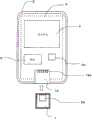
图1是本实施方式的生物试样测定装置的立体图;图2是其剖视图;图3是其顶面图;图4是其控制方框图。如图1所示,本实施方式的生物试样测定装置包括在其一端具有传感器插入单元1的主体外壳2。在传感器插入单元1中可插入具有点滴单元11a的传感器11。1 is a perspective view of a biological sample measuring device according to this embodiment; FIG. 2 is a cross-sectional view thereof; FIG. 3 is a top view thereof; and FIG. 4 is a control block diagram thereof. As shown in FIG. 1 , the biological sample measurement device of the present embodiment includes a
在主体外壳2的上表面设有显示单元3、操作按钮14和15。如图2所示,传感器插入单元1配置在位于主体外壳2内部的基板(电路板)4的一端。另外,如图2和图3所示那样,在传感器插入单元1中配置有加速度传感器5。On the upper surface of the
在传感器插入单元1的内部设有与被插入的生物试样测定传感器11电连接的连接器单元(未图示)。通过将生物试样测定传感器11插入到传感器插入单元1中,从而经由该连接器单元,构成在基板4上的测定单元和生物试样测定传感器11的连接单元被电连接。A connector unit (not shown) electrically connected to the inserted biological
加速度传感器5优选配置成与该连接器单元相邻。这样,加速度传感器5配置在控制元件6附近且在基板4上,即,配置在具有测定单元或控制单元功能的控制元件6附近且在基板4上。另外,加速度传感器5配置在传感器插入单元1的附近。The
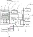
在基板4的上表面配置有被称为微机的控制元件6。如图4所示,控制元件6包括连接有传感器插入单元1的测定单元7、连接了该测定单元7的控制单元8、连接了所述加速度传感器5的判定单元9、连接了判定单元9的存储器单元10。判定单元9和存储器单元10连接到控制单元8。A
另外,在传感器插入单元1设有检测生物试样测定传感器11的插入的插入检测单元12,插入检测单元12连接到控制单元8。进而,显示单元3、作为报警单元的一例的蜂鸣器13、操作按钮14及15连接着控制单元8。In addition, the
参照图5说明在具有以上结构的生物试样测定装置中测定血糖值的流程。首先,说明基本的测定流程。为了进行测定,首先如图1所示那样,将生物试样测定传感器11(血糖值传感器)插入到传感器插入单元1中。通过插入检测单元12检测传感器的插入,从而电源变为接通状态(图5的步骤S1)。之后,对图1的状态下的生物试样测定传感器11的点滴单元11a,点滴从穿刺后的手指渗出的血液(图5的步骤S5)。点滴到的血液从点滴单元11a到达位于生物试样测定传感器11内的试剂(未图示),利用该试剂与血液产生电化学反应。由测定单元7测定该化学反应的信号(图5的S10),将其测定结果显示在显示单元3上(图5的S12)。The flow of blood glucose level measurement in the biological sample measuring device having the above configuration will be described with reference to FIG. 5 . First, the basic measurement flow will be described. To perform the measurement, first, the biological sample measurement sensor 11 (blood sugar level sensor) is inserted into the
进而,在本实施方式中,在上述的步骤S1和步骤S5之间,以及步骤S5~步骤S10之间,检测是否有过大的冲击施加到传感器插入单元1上。具体而言,在图5的S2(测定前)和/或S7(测定中)中,将来自加速度传感器5的输出输入到判定单元9。然后,在判定单元9中,判定该输出值是否为预先设定的预定值以上(步骤S3和/或S8)。在判定单元9中判定出的冲击小于预定值时,判断为没有异常而分别转移到步骤S5和步骤S10。另一方面,在判定单元9中判定出的冲击为预定值以上时,在步骤S4或步骤S9中,将“有了过大冲击”这样的标记记录到存储器单元10中。Furthermore, in this embodiment, it is detected whether or not an excessive impact is applied to the
在步骤S10中测定完成后,则在步骤S11中,控制单元8判定所述标记是否输入到存储器单元10。在存储有该标记的情况下,将错误显示显示在显示单元3上。也可以是,与显示一起,由蜂鸣器13发出错误警告。After the measurement is completed in step S10 , then in step S11 , the
图6(a)~图6(d)表示显示在显示单元3上的错误显示的例子。图6(a)是以点阵示出受到了冲击的错误显示;图6(b)是以错误码(段式显示的情况)示出受到了冲击的错误显示。在实施方式3中说明图6(c)和图6(d)。6( a ) to 6( d ) show examples of error displays displayed on the
在将从穿刺后的手指渗出的血液点滴到生物试样测定传感器11的点滴单元11a的情况下,在将该手指从生物试样测定传感器11离开时,容易对传感器插入单元1施加过大的冲击。即,此时,有时手指弹开生物试样测定传感器11的点滴单元11a。由于用手指弹开的冲击,点滴出的血液无法顺畅地到达生物试样测定传感器11内的试剂部分。作为其结果,测定精度将会变低。When the blood oozing from the finger after puncturing is instilled on the
因此,在本实施方式中,利用加速度传感器5检测对传感器插入单元施加1的过大的冲击。在检测到过大的冲击时,在显示单元3上进行错误显示。由此,抑制不适当的测定值被显示出来。由此在本实施方式中,提高测定精度。Therefore, in the present embodiment, the
在本实施方式中,为了通过加速度传感器5检测对传感器插入单元1施加的过大的冲击,如图3所示,在传感器插入单元1配置有加速度传感器5。具体而言,采用如下的结构:在传感器插入单元1之处的基板4上安装有加速度传感器5。In the present embodiment, in order to detect an excessive impact applied to the
加速度传感器5优选是三维式加速度传感器。三维式加速度传感器能够分别测量X、Y、Z各轴方向的加速度分量。因此,根据三维式加速度传感器,能够记录冲击的方向和冲击力,能够更详细地掌握传感器插入单元1受到的冲击。The
三维加速度传感器(也称为三轴加速度传感器)有压电电阻式、静电电容式、热检测式等。三维加速度传感器也应用于以移动电话、游戏控制器、硬盘的振动检测、机器人的姿态控制等。Three-dimensional acceleration sensors (also referred to as three-axis acceleration sensors) include piezoresistive, electrostatic capacitance, thermal detection, and the like. Three-dimensional acceleration sensors are also used in mobile phones, game controllers, vibration detection of hard disks, attitude control of robots, etc.
压电电阻式三维加速度传感器是指,利用硅半导体的制造技术,将表面呈圆环状较薄地制造而形成隔膜;以该较薄的金属支承位于中央的锭子,从而容易检测加速度导致的位移;由压电电阻元件检测隔膜的位置变化;利用电子电路进行放大和测量的传感器。静电电容式三维加速度传感器是指将以梁构造支承的微小的可动部中的微小位置变化作为静电电容的变化进行检测;利用电子电路进行放大、计量的传感器。热检测式三维加速度传感器是指,利用加热器使热气流产生在加速度传感器机壳内,利用热电阻等检测加速度引起的对流的变化的传感器。The piezoresistive three-dimensional acceleration sensor refers to the use of silicon semiconductor manufacturing technology to make the surface thinner in a ring shape to form a diaphragm; the thinner metal supports the spindle in the center, making it easy to detect displacement caused by acceleration; The change in position of the diaphragm is detected by piezoresistive elements; a sensor that uses electronic circuits for amplification and measurement. A capacitive three-dimensional acceleration sensor is a sensor that detects a small change in the position of a tiny movable part supported by a beam structure as a change in capacitance, and uses an electronic circuit to amplify and measure. The thermal detection type three-dimensional acceleration sensor refers to a sensor that uses a heater to generate hot air flow in the acceleration sensor housing, and uses a thermal resistor to detect changes in convection caused by acceleration.
这里使用的加速度传感器为静电电容式三维加速度传感器,其测定范围为例如-2g~+2g(g:重力加速度)。标准重力加速度是1.0G=约9.8m/s2。The acceleration sensor used here is a capacitive three-dimensional acceleration sensor, and its measurement range is, for example, -2g to +2g (g: gravitational acceleration). The standard gravitational acceleration is 1.0G = about 9.8m/s2 .
进而,还能够构成为,比较加速度传感器检测到的冲击与主体外壳2等的耐久性,根据需要对用户通知促使生物试样测定装置的早期交换。在此,“主体外壳2的耐久性”是指,在测定装置的品质评价、出货检查中的主体外壳的机械强度试验(例如测定装置的落下试验等)等中所评价的、表示作为测定装置的機械强度的品质保证范围的耐久性能。在机械强度试验中,具体而言,试验是否有可能在进行了成品的测定装置的落下试验(例如,从1m的高度落到床上的试验等)的情况下,安装在测定装置内的基板上的零部件脱落、在基板等中产生裂缝、或者零部件本身被破坏,由此对作为测定装置的性能带来影响。Furthermore, it may be configured to compare the shock detected by the acceleration sensor with the durability of the
[实施方式2][Embodiment 2]
如图7所示,本实施方式的生物试样测定装置中,将加速度传感器5配置在主体外壳2内部的基板4之上。这样配置的加速度传感器5能够主要检测主体外壳2的整体受到的冲击。作为“主体外壳2的整体受到冲击”的情况,可以假定例如在测定中使主体外壳2落下的情况、以及因不注意使主体外壳2碰到周围的物体的情况等。As shown in FIG. 7 , in the biological sample measurement device according to the present embodiment, the
[实施方式3][Embodiment 3]
如图8所示,本实施方式的生物试样测定装置装载了两个加速度传感器5a、5b。一个加速度传感器5a与实施方式1所示的情况同样地设置在基板4的传感器插入单元1所对应的位置上;另一个加速度传感器5b与实施方式2所示的情况同样地设置在主体外壳2内部的基板4上。As shown in FIG. 8 , the biological sample measurement device according to this embodiment is equipped with two
在本实施方式中,将两个加速度传感器5a、5b分别设置在不同的位置,因此能够相互灵活运用各自的加速度传感器的检测结果,详细地检测冲击的种类。由此,能够进一步提高测定的可靠性。In the present embodiment, since the two
具体而言,加速度传感器5a能够检测在将血液点滴到安装于传感器插入部1上的生物试样测定传感器11的点滴单元11a的情况下,以手指等弹出所述生物试样测定传感器11时的冲击等。另外,加速度传感器5a在主体外壳2整体受到了冲击时也能够进行检测。另一方面,加速度传感器5b配置在主体外壳2内部的中央附近,因此能够检测对主体外壳2的整体施加的冲击,但不足够用于检测弹开生物试样测定传感器11引起的冲击等较小冲击。Specifically, the
因此,在仅加速度传感器5a检测到大于预定值的冲击时,判断为在点滴时用户的手指弹开了生物试样测定传感器11。然后,显示单元3显示图6(c)所示的错误消息。另一方面,加速度传感器5a、5b双方检测到大于预定值的冲击时,判断为主体外壳2整体受到了冲击,在显示单元3显示图6(d)所示的错误消息,能够提醒用户注意。Therefore, when only the
[实施方式4][Embodiment 4]
本实施方式的生物试样测定装置与实施方式3同样地装载两个加速度传感器,但如图9和图10所示那样,传感器插入单元1构成为可在主体外壳2上拆卸。即,本实施方式的生物试样测定装置构成为包括设有加速度传感器5b和安装单元16的主体外壳2、设有加速度传感器5a和插入检测部12的传感器插入单元1,传感器插入单元1能够可拆卸地安装在安装单元16上。The biological sample measuring device of this embodiment is equipped with two acceleration sensors as in the third embodiment, but as shown in FIGS. 9 and 10 , the
如图9所示,在安装单元16设有具有多个接点端子的连接器单元16a。如图10所示,当传感器插入单元1安装在安装单元16上时,构成传感器插入单元1的加速度传感器5a和插入检测单元12的信号经由连接器单元16a被发送到主体外壳2内的基板4上的控制元件6所包含的判定单元9和控制单元8。As shown in FIG. 9 , the mounting
在测定生物试样时,插入到传感器插入单元1的生物试样测定传感器11的信号经由连接器单元16a而发送到配置在控制元件6内的测定单元7。然后,进行生物试样(例如血液等)的测定(例如,血糖值测定)。When measuring a biological sample, a signal from the biological
主体外壳2的安装单元16也可以与基板4为一体。即,在安装了控制元件6的基板4上设置构成连接器单元16a的多个接点端子,从而构成安装单元16。The
也可以是,在可交换的传感器插入单元1上,设置加速度传感器5a及其以外的传感器(例如温度传感器、湿度传感器等)。It is also possible to install the
图10示出本实施方式的生物试样测定装置的控制方框图。图10所示的控制方框与实施方式1和实施方式2的控制方框(图4)不同,具有两个加速度传感器5a、5b,两个加速度传感器5a、5b连接到控制元件6的判定单元9。加速度传感器5a的信号经由连接器部16a而发送到判定单元9。即,加速度传感器5a和5b的加速度信息(输出信息)被输入到判定单元9。FIG. 10 shows a control block diagram of the biological sample measurement device of this embodiment. The control block shown in FIG. 10 is different from the control block ( FIG. 4 ) of
在本实施方式的生物试样测定装置中,能够更换传感器插入单元1,因此能够在传感器插入单元1及其周边有污垢的情况(例如附着了血液的情况)等中进行更换。因此,具有容易进行清扫等、保养、维护性优异的优点,能够在卫生方面维持生物试样测定装置,最终有助于生物试样测定装置的稳定运行等的可靠性提高。In the biological sample measurement device according to the present embodiment, the
[实施方式5][Embodiment 5]
如图11所示,本实施方式的生物试样测定装置中,加速度传感器5a设置在传感器插入单元1上,加速度传感器5b设置在基板4上。图11示出本实施方式的生物试样测定装置的传感器插入单元1附近的内部剖视图,表示生物试样测定传感器11被插入到传感器插入单元1中的状态。生物试样测定传感器11的连接端子(未图示)与接触片(contact pin)20的接触部21接触并电连接。此外,在图11中,控制单元等主要的电子电路部分为了方便而省略。As shown in FIG. 11 , in the biological sample measurement device according to this embodiment, the
加速度传感器5a与接触片20接触地配置。另外,加速度传感器5a通过导线29与基板4电连接。插入到传感器插入单元1中的生物试样测定传感器11的前端(连接端子)与突起22卡止。即,突起22具有作为生物试样测定传感器11的固定器功能。图11示出生物试样测定传感器11与突起22卡止的状态,即,生物试样测定传感器11正确地设置在传感器插入单元1中的状态。The
图8的生物试样测定装置具有作为传感器插入单元1的一部分的、设置在基板4上的加速度传感器5a,而图11的生物试样测定装置具有作为传感器插入单元1的一部分的、安装成与接触片20接触的加速度传感器5a。The biological sample measurement device of FIG. 8 has an
生物试样测定传感器11被插入到传感器插入单元1时,接触片20沿箭头X方向弯曲。与接触片20接触而安装的加速度传感器5a检测接触片20的振动。这样,能够由加速度传感器5a检测生物试样测定传感器11的插入。同样地,加速度传感器5a也能够检测生物试样测定传感器11从传感器插入单元1的排出。When the biological
通过做成这样的结构,能够由加速度传感器5a可靠地检测出在将从手指渗出的血液点滴到生物试样测定传感器11的点滴单元11a时,被手指变为“弯曲”状态的生物试样测定传感器11猛烈地消除了该弯曲时的冲击、以及在测定中手指等接触到生物试样测定传感器产生的冲击等。在检测到该冲击的情况下,测定值无法可靠的可能性高,因此能够不显示测定值,作为测定不合格而进行警告显示。With such a configuration, the
通过在测定中接受冲击,从而生物试样测定传感器11内的试剂等从预定位置移动,测定值(血糖值)发生错误而过小或过大。若测定值过小或过大,则有可能被投药错误量的胰岛素,从而产生事故。特别是测定值过小的情况下,基于该过小的测定值将投药大于需要的胰岛素,导致产生陷入低血糖这种非常危险的状态的事故。本发明的血液检查装置能够可靠地防止这样的问题。The reagent etc. in the biological
在生物试样测定传感器11安装到传感器插入单元1后,将血液等点滴到生物试样测定传感器11的点滴单元11a,从而开始测定。当测定结束后,在显示单元显示测定结果。在进行该测定的期间,安装在接触片20上的加速度传感器5a、设置在基板4上的加速度传感器5b监视是否受到了来自外部的冲击。在测定中检测到超过预定值的冲击时,判断为测定出的血糖值的可靠性出现问题。然后,不显示测定值,而进行表示“在测定中存在冲击,为测定不合格”含义的警告显示,促使重新进行测定。After the biological
更具体而言,在加速度传感器5a和加速度传感器5b双方检测到超过预定值的冲击时,判断为测定装置自身碰到某物体而受到了冲击,显示测定错误。然后,显示促使确认能否进行测定装置的设备本身的操作的警告。More specifically, when both the
在仅加速度传感器5a检测到大于预定值的冲击时,判断为有可能在测定中手指触到生物试样测定传感器11,显示测定错误。然后,显示重新测定和请求谨慎操作的注意。When only the
在血糖值等的测定完成后,用手摘除出已使用完毕的生物试样测定传感器11并将其废弃。加速度传感器5a也能够检测这些排出动作引起的冲击。这样,加速度传感器5a还能够检测生物试样测定传感器11的插入和排出两者。After the measurement of the blood sugar level and the like is completed, the used biological
也可以是,将图11中的设置在传感器插入单元1上的加速度传感器5a的灵敏度与基板4上的加速度传感器5b的灵敏度设定为不同的测定范围。例如,将加速度传感器5a的灵敏度设为是加速度传感器5b的2倍~10倍左右的高灵敏度。作为更具体的例子,考虑作为加速度传感器5a使用测定范围为-2g~+2g的加速度传感器,作为加速度传感器5b使用测定范围为-6g~+6g的加速度传感器的情况等。由此,能够以更高的灵敏度测定因测定中接触到生物试样测定传感器产生的冲击,并使冲击的检测精度提高。Alternatively, the sensitivity of the
为了提高测定操作的可靠性,也可以设定以下的阈值L1~L3。阈值L1是用于检测生物试样测定传感器11的插入或排出的阈值,例如在0.01g~0.3g左右的范围内设定即可。另外,阈值L2是用于检测测定中手指等是否接触到生物试样测定传感器(用于检测测定值有可能无可靠性)的阈值,例如,为0.005g~0.3g左右的范围即可。进而,阈值L3是用于判断为无法进行测定本身的阈值,例如优选为0.5g以上。In order to improve the reliability of the measurement operation, the following thresholds L1 to L3 may be set. The threshold L1 is a threshold for detecting insertion or discharge of the biological
阈值L1~L3的关系,例如设为以下那样的关系。The relationship between the thresholds L1 to L3 is, for example, the following relationship.
(1)L1<L3(1) L1<L3
(2)L2<L3(2) L2<L3
(3)L1≤L2或L1>L2(3) L1≤L2 or L1>L2
这里,在将阈值L1与阈值L2的关系设为L1>L2时,则即使是小于生物试样测定传感器11的插入或排出时的冲击(加速度)的冲击(加速度),也判断为错误,因此能够确保更高的安全性。Here, when the relationship between the threshold L1 and the threshold L2 is L1>L2, even if the impact (acceleration) is smaller than the impact (acceleration) when the biological
另外,阈值L1~L3也可以与加速度传感器5a和加速度传感器5b两者测定出的加速度数据进行比较,根据其目的,阈值L1和阈值L2与主要由设置在传感器插入单元1的加速度传感器5a测定出的加速度数据相比较是有效的,阈值L3与由设置在基板4上的加速度传感器5b测定出的加速度数据相比较是有效的。据此也可以是,如上述那样作为加速度传感器5a和加速度传感器5b选择不同灵敏度的加速度传感器。In addition, the threshold values L1-L3 can also be compared with the acceleration data measured by both the
安装在传感器插入单元1(图11中的接触片20之上)上的加速度传感器5a和配置在装置内部的基板4上的加速度传感器5b,优选均为三维加速度传感器。The
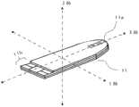
图12a示出三维加速度传感器的各轴(X轴、Y轴、Z轴)与生物试样测定传感器之间的关系。在图12a中,X轴与板状的生物试样测定传感器11的长度方向平行,Y轴与上述X轴正交,Z轴与X轴和Y轴分别垂直、即相对于X-Y平面垂直。该关系为一例,基准轴只要在多个加速度传感器全部被设定为相同,则没有问题。即,在图12a中,将与生物试样测定传感器的长度方向平行的方向定义为X轴,将该X轴作为基准;但也可以将与生物试样测定传感器的长度方向平行的方向定义为Y轴,将Y轴设为基准轴,还可以将与生物试样测定传感器的长度方向平行的方向定义为Z轴,将Z轴作为基准轴。即,只要将多个三维加速度传感器的X轴之间、Y轴之间,Z轴之间分别设为相同(同一方向)则没有问题。Fig. 12a shows the relationship between the axes (X-axis, Y-axis, Z-axis) of the three-dimensional acceleration sensor and the biological sample measurement sensor. In FIG. 12a, the X-axis is parallel to the longitudinal direction of the plate-shaped biological
说明利用图12a所示的三维加速度传感器5a测定出的测定加速度GA与利用三维加速度传感器5b测定出的测定加速度GB。加速度GA和GB如下述那样表示。在此,如图12b所示,示出表示方向和力的矢量值。在此,GAx表示GA的x分量、GAy表示GA的y分量、Gaz表示GA的z分量。同样地,GBx表示GB的x分量、Gby表示GB的y分量、GBz表示GB的z分量(以下同样)。The measured acceleration GA measured by the three-
GA=GAx+GAy+GAz(表示X、Y、Z轴分量的矢量总和)GA=GAx+GAy+GAz (represents the vector sum of X, Y, Z axis components)
GB=GBx+GBy+GBz(表示X、Y、Z轴分量的矢量总和)GB=GBx+GBy+GBz (represents the vector sum of X, Y, Z axis components)
将测定加速度GA和GB根据其测定时而如下述那样定义。The measured accelerations GA and GB are defined as follows according to the time of measurement.
将生物试样测定传感器11插入到传感器插入单元1时测定出的测定加速度:GA1、GB1Measurement acceleration measured when biological
在血糖值测定中测定出的测定加速度:GA2、GB2(测定加速度GA2和GB2不限于各自为1个,通常测定多次)Measurement acceleration measured in blood glucose level measurement: GA2, GB2 (measurement acceleration GA2 and GB2 are not limited to one each, and are usually measured multiple times)
将生物试样测定传感器11从传感器插入单元1排出时测定出的测定加速度:GA3、GB3Measurement acceleration measured when the biological
能够基于测定加速度GA2和GB2如以下那样判断。在测定加速度GA2、GB2无法测定时,判断为生物试样测定装置自身错误(故障)。在“测定加速度GA2、GB2>阈值L3”时,判断为无法测定生物试样,请求确定是否为测定装置的故障以及重新测定。在“阈值L3>测定加速度GA2、GB2>阈值L2”时,判断为有可能没有进行适当的测定,请求更换生物试样测定传感器重新进行测定。在“测定加速度GA2、GB2≤阈值L2”时,判断为进行了适当的测定。Based on the measured accelerations GA2 and GB2, it can be determined as follows. When the measurement accelerations GA2 and GB2 cannot be measured, it is determined that the biological sample measurement device itself is faulty (failure). In the case of "measurement acceleration GA2, GB2>threshold value L3", it is determined that the biological sample cannot be measured, and it is requested to determine whether or not the measurement device is faulty and to re-measure. In the case of "threshold value L3>measurement acceleration GA2, GB2>threshold value L2", it is determined that there is a possibility that an appropriate measurement has not been performed, and it is requested to replace the biological sample measurement sensor and perform measurement again. When "measurement acceleration GA2, GB2≦threshold value L2", it is determined that appropriate measurement has been performed.
当然,也能够仅比较测定加速度GA2和阈值L2,判断是否进行了适当的测定。另外,在加速度传感器5a、5b的灵敏度不同时,分别比较对从加速度传感器5a和5b输入的数据进行灵敏度换算得到的测定加速度GA2、GB2与阈值L2、L3。通过判定单元9或控制单元8(参照图10等)进行灵敏度换算。Of course, it is also possible to judge whether or not an appropriate measurement has been performed by simply comparing the measured acceleration GA2 with the threshold value L2. Also, when the sensitivities of the
另外,也能够基于测定加速度GA2、GB2的X、Y、Z轴分量(测定加速度分量)如以下那样进行判断。在“测定加速度分量GA2x、GA2y、GA2z、GB2x、GB2y或GB2z>阈值L3”时,判断为在血糖值测定中受到冲击,无法进行血糖值测定。在为“测定加速度分量GB2z(或GB2x、GB2y)>阈值L2”时,判断为有可能在测定中受到冲击,没有进行适当的血糖值测定。在“测定加速度分量GA2x、GA2y、GA2z、GB2x、GB2y和GB2z≤阈值L2”时,判断为进行了适当的测定。In addition, determination can also be made as follows based on the X, Y, and Z axis components (measured acceleration components) of the measured accelerations GA2 and GB2. In the case of "measurement acceleration component GA2x, GA2y, GA2z, GB2x, GB2y, or GB2z>threshold value L3", it is determined that a shock has been received during the blood sugar level measurement, and the blood sugar level measurement cannot be performed. When "measurement acceleration component GB2z (or GB2x, GB2y)>threshold value L2", it is determined that there is a possibility of shock during the measurement, and appropriate blood sugar level measurement has not been performed. When "measurement acceleration components GA2x, GA2y, GA2z, GB2x, GB2y, and GB2z≦threshold value L2", it is determined that appropriate measurement has been performed.
以下详细说明由手指等弹开了生物试样测定传感器的情况。图12c示出在血糖值等的测定中手指等触碰到生物试样测定传感器11时,从三维加速度传感器5a输出的一个信号、即Z轴方向的输出信号波形Wg的一例。在此,研究根据传感器插入单元、接触片之间的配置关系,在垂直于生物试样测定传感器11的平面的方向、即Z轴方向显著变动的情况。The case where the biological sample measurement sensor is flicked off by a finger or the like will be described in detail below. 12c shows an example of an output signal waveform Wg in the Z-axis direction, which is one signal output from the three-
在手指等触碰到生物试样测定传感器11,或者从弯曲了生物试样测定传感器11的状态释放的情况下,从加速度传感器5a输出图12c那样的振动波形即输出信号Wg。即,GAz的测定加速度的值为相对于中心:0在上下(即正/负)方向较大地振动,同时随着时间t的推移衰减。When the biological
从三维加速度传感器5a将Z轴方向测定加速度的值的变化即输出信号Wg的数据输入到判定单元9,并存储到存储器单元10中。比较这些加速度传感器5a的测定加速度数据与阈值L2,在判定单元9中判定是否超过阈值L2。具体而言,Z轴输出信号Wg的初始峰值(正侧峰值即P1、P3、P5等、以及负侧峰值即P2、P4、P6等),将这些值与加速度传感器5a的测定中的判定用阈值L2进行比较。然后,在峰值P1超过正侧阈值L2(+L2)时、或者峰值P2低于负侧阈值L2(-L2)时判断为错误。From the three-
另外,在图12c的例子中可知,输出信号Wg具有超过阈值+L2的正侧峰值:P1和P3,为振动波形。同样地,可知输出信号Wg具有低于阈值-L2的负侧峰值:P2和P4,为振动波形。这样,检测多个峰值可判别出为振动波形,判别为不是测定装置的掉落或测定装置与外部的某物体的冲撞,而是“手指等触碰到生物试样测定传感器”导致的错误。In addition, in the example of FIG. 12c, it can be seen that the output signal Wg has positive side peaks exceeding the threshold value +L2: P1 and P3, which are oscillation waveforms. Likewise, it can be seen that the output signal Wg has a negative side peak value lower than the threshold value -L2: P2 and P4, which are vibration waveforms. In this way, by detecting multiple peaks, it can be determined that it is a vibration waveform, and it is determined that it is not a fall of the measurement device or a collision between the measurement device and an external object, but an error caused by "a finger or the like touching the biological sample measurement sensor".
另一方面,在产生了“测定装置的掉落或测定装置与外部的某物体的冲撞”的情况下,往往不会成为图12c所示那样的振动波形,而表示仅1次的峰值。即,并不是如图12c所示那样的、峰值相对于时间逐渐衰减的波形,而往往是如图12d所示那样的、在冲击时出现了较大的峰值后,波形的波峰一下子衰减这样的波形。On the other hand, when "the measurement device is dropped or the measurement device collides with an external object", the vibration waveform shown in FIG. 12c may not be obtained, but only one peak value may be shown. That is, it is not a waveform whose peak value gradually decays with respect to time as shown in Figure 12c, but rather a waveform whose peak value is suddenly attenuated after a large peak value appears at the time of impact, as shown in Figure 12d waveform.
图12d是示出出现“测定装置的掉落或测定装置与外部的某物体的冲撞”时的三维加速度传感器5a的Z轴分量的输出信号Wg的一例。在该例子中,冲击时的波峰P1表示不仅超过阈值+L2,而且还超过正侧阈值L3(+L3:L3是前述的“用于判断为无法进行测定本身的阈值”)的高峰值。即,通过将静电电容型的三维加速度传感器5a的测定加速度GA(测定中相当于GA2)的Z轴分量的测定加速度数据的峰值P1与阈值L3(+L3)进行比较,从而判别错误。即,能够进行基于冲击的大小的判别。同样地,负侧的最大值即波峰P2的峰值低于负侧阈值L3(-L3)时,判断为认为“测定装置的掉落或测定装置与外部的某物体的冲撞”的错误。Fig. 12d shows an example of the output signal Wg of the Z-axis component of the three-
图12d是P1和P2双方的峰值大于阈值L3的例子,但不限于这样的情况,还存在仅波峰P1大于阈值L3的情况,或者仅波峰P2大于阈值L3的情况。这是因为,产生冲击的强度、冲击的方向各不相同,并不一定固定。因此,需要将正侧和负侧双方的峰值与阈值(+L3,-L3等)进行比较。12d is an example where the peaks of both P1 and P2 are greater than the threshold L3, but it is not limited to this case, and there are cases where only the peak P1 is greater than the threshold L3, or only the peak P2 is greater than the threshold L3. This is because the intensity and the direction of the impact vary and are not necessarily fixed. Therefore, it is necessary to compare both the positive and negative peaks with threshold values (+L3, -L3, etc.).
另外,在图12d时,由于不是如图12c那样为振动波形,因此也能够判别是与“手指触碰到生物试样测定传感器”导致的错误不同的错误。In addition, in FIG. 12d , since it is not a vibration waveform as in FIG. 12c , it can also be determined that the error is different from the error caused by "the finger touches the biological sample measurement sensor".
如上所述,在本发明中,通过监视来自加速度传感器的输出信号Wg,除了判别冲击的大小以外,还确认输出信号Wg的波形(是否为振动波形等),从而能够判别该冲击的原因。由此,能够对用户进行生物试样测定中的正确的注意、警告的指示、显示、通知,能够保证测定装置的稳定使用、提高可靠性。As described above, in the present invention, the cause of the shock can be determined by monitoring the output signal Wg from the acceleration sensor and checking not only the size of the shock but also the waveform (whether it is a vibration waveform, etc.) of the output signal Wg. Thereby, the user can be instructed, displayed, and notified of the correct precautions and warnings during the measurement of the biological sample, and the stable use of the measurement device can be ensured and the reliability can be improved.
图12c示出逐渐衰减的振动波形的一例,但波形的形状不限于此。对于图12c所示那样的振动波形,也存在峰值、振动的频率或周期、衰减时间等要素不同的情况,因此有可能出现各种波形形状。进而,不仅观测到振动波形,有时也在测定装置掉落时等观测到短暂波形。这样,在对测定装置的来自外部的冲击中有各种形态,考虑到各种波形图案。FIG. 12c shows an example of a gradually attenuating vibration waveform, but the shape of the waveform is not limited thereto. The vibration waveform as shown in FIG. 12c may also have different elements such as peak value, frequency or period of vibration, and decay time, so various waveform shapes may appear. Furthermore, not only vibration waveforms but also transient waveforms may be observed when the measurement device is dropped. In this way, there are various forms of external impact on the measurement device, and various waveform patterns are considered.
受到冲击的方向与X轴、Y轴或Z轴方向大致平行时,也可以将测定加速度分量与阈值L2或L3相比较。另一方面,受到冲击的方向不与X、Y或Z轴方向平行时,沿着各轴的分量(GB2x、GB2y、GB2z等)与所合成的矢量值(GA2、GB2等;参照图12b)存在差量。因此,不仅比较测定加速度的各成分(GB2x,GB2y、GB2Z等)与阈值L1~L3,还比较所合成的测定加速度GA2、GB2与各阈值L1~L3,若并用上述两者的比较进行判断,则更为正确。When the impacted direction is substantially parallel to the X-axis, Y-axis or Z-axis direction, the measured acceleration component may be compared with the threshold value L2 or L3. On the other hand, when the impacted direction is not parallel to the X, Y, or Z axis directions, the components along each axis (GB2x, GB2y, GB2z, etc.) There is a variance. Therefore, not only comparing each component of the measured acceleration (GB2x, GB2y, GB2Z, etc.) is more correct.
[实施方式6][Embodiment 6]
图13示出用于进行血糖值测定的施加电压的波形图案的例子。这里,说明加速度传感器的测定定时(timing)。图13示出为了测定血糖值(葡萄糖值)而从测定装置对生物试样测定传感器的检测电极(作用极、对极等用于测定的电极)供给的施加电压的波形。图13示出施加三个多脉冲波形(矩形波)的情况。FIG. 13 shows an example of a waveform pattern of an applied voltage for measuring a blood sugar level. Here, measurement timing (timing) of the acceleration sensor will be described. FIG. 13 shows waveforms of applied voltages supplied from the measurement device to detection electrodes (electrodes for measurement such as working electrodes and counter electrodes) of a biological sample measurement sensor for measuring a blood sugar level (glucose level). FIG. 13 shows the case where three multi-pulse waveforms (rectangular waves) are applied.
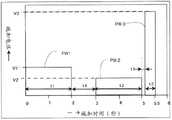
具体而言,在脉冲PW1中,从测定开始时经过t1时间(0.5~5秒左右,此例中为2秒钟)、施加电压V1(可在100~800mV的范围内,此例中为350mV)。之后的t4时间(0.1~3秒左右,此例中为1秒钟)不施加电压。接着,在脉冲PW2,再次在t2时间(0.5~5秒,此例中为2秒钟)施加电压V2(可在100~800mV的范围内,此例中为250mV)。之后的t5时间(0~1.0秒,此例中为0.1秒)不施加电压。进而,在脉冲PW3中,在t3时间(0.1~2秒,此例中为0.5秒)施加电压V3(1.5~3.5V,此例中为2.5V)。Specifically, in the pulse PW1, after the time t1 (about 0.5 to 5 seconds, 2 seconds in this example) has elapsed from the start of the measurement, the applied voltage V1 (which can be in the range of 100 to 800 mV, 350 mV in this example) ). No voltage is applied for the subsequent time t4 (about 0.1 to 3 seconds, 1 second in this example). Next, in the pulse PW2, the voltage V2 (which can be in the range of 100-800 mV, 250 mV in this example) is applied again for the time t2 (0.5-5 seconds, 2 seconds in this example). No voltage is applied for the subsequent time t5 (0 to 1.0 second, 0.1 second in this example). Furthermore, in pulse PW3, voltage V3 (1.5-3.5V, 2.5V in this example) is applied for time t3 (0.1-2 second, 0.5 second in this example).
这里,脉冲PW1和脉冲PW2表示用于测定葡萄糖的电压施加,或表示用于测定干扰物质(对葡萄糖值测定带来影响的物质)的电压施加。另外,脉冲PW3示出用于测定Hct(血球比率)值的电压施加。Here, pulse PW1 and pulse PW2 represent voltage application for measuring glucose, or voltage application for measuring interfering substances (substances that affect glucose level measurement). In addition, the pulse PW3 shows voltage application for measuring the Hct (hematocrit) value.
另外,图14示出在施加了图13所示的脉冲施加电压时,例如在血糖值测定中,来自生物试样测定传感器的检测电极(作用极、对极等)的输出信号。W1示出施加了脉冲电压PW1(施加电压V1、施加时间t1)时的来自检测电极(作用极、对极等)的输出信号。W2示出了施加了脉冲电压PW2(施加电压V2、施加时间t2)时的输出信号。它是生物试样测定传感器中的氧化还原反应引起的反应电流、即与葡萄糖值对应的输出信号。另外,W3示出施加了脉冲电压PW3(施加电压V3、施加时间t3)时的来自Hct电极的输出信号。即,是与Hct值对应的输出信号。基于葡萄糖值、Hct(血球比率)值以及其他的数据(温度数据、干扰物质的数据等),求基准温度中的葡萄糖值(血糖值)。In addition, FIG. 14 shows output signals from detection electrodes (working electrode, counter electrode, etc.) of the biological sample measurement sensor when the pulsed voltage shown in FIG. 13 is applied, for example, in blood glucose level measurement. W1 shows an output signal from the detection electrode (working electrode, counter electrode, etc.) when the pulse voltage PW1 is applied (applied voltage V1, applied time t1). W2 shows the output signal when the pulse voltage PW2 is applied (applied voltage V2, applied time t2). This is a reaction current caused by an oxidation-reduction reaction in the biological sample measurement sensor, that is, an output signal corresponding to a glucose value. In addition, W3 shows the output signal from the Hct electrode when the pulse voltage PW3 is applied (applied voltage V3, applied time t3). That is, it is an output signal corresponding to the Hct value. Based on the glucose level, the Hct (hematocrit) value, and other data (temperature data, interfering substance data, etc.), the glucose level (blood sugar level) at the reference temperature is obtained.
在这样测定葡萄糖值的期间,若从外部对测定装置施加了冲击时,与血液发生了溶解的反应中的试剂从预定位置(例如检测电极上)偏离,没有充分地引起适当的反应,从而葡萄糖值的测定值不正确,或者无法进行测定本身。对测定装置施加了冲击的情况,考虑为从外部对测定装置施加了冲击、测定装置掉落、或者手指触碰到生物试样测定传感器、在将血液点滴到生物试样测定传感器时强力按下生物试样测定传感器而使其弯曲的情况等。During the measurement of the glucose value in this way, if an impact is applied to the measurement device from the outside, the reagent in the reaction that dissolves with the blood deviates from the predetermined position (for example, on the detection electrode), and an appropriate reaction is not sufficiently caused, so that the glucose The measured value of the value is incorrect, or the measured value itself cannot be performed. When an impact is applied to the measurement device, it is considered that an impact is applied to the measurement device from the outside, the measurement device is dropped, or the biological sample measurement sensor is touched by a finger, and the biological sample measurement sensor is pressed down strongly when blood is dripped onto the biological sample measurement sensor. When a biological sample is measured and the sensor is bent, etc.
通过使用装载了加速度传感器的测定装置,从而解决该问题。即,在正确地检测在测定中是否产生了冲击,在测定中检测到冲击时,判断为测定数据不正确。因此,不显示测定数据,进行错误显示,催促重新测定等。其结果是,在显示单元仅显示可靠的测定值,作为测定装置的可靠性提高。This problem can be solved by using a measuring device equipped with an acceleration sensor. That is, it is correctly detected whether or not a shock has occurred during the measurement, and when a shock is detected during the measurement, it is determined that the measurement data is incorrect. Therefore, the measurement data is not displayed, an error display is performed, and re-measurement is urged. As a result, only reliable measured values are displayed on the display unit, improving the reliability of the measuring device.
另外,若在施加脉冲电压PW1、PW2或PW3中被予以冲击,则往往图15中的输出信号W1、W2或W3也成为不正常的波形。因此,也能够根据输出信号W1、W2或W3的波形检测受到了冲击。但是,在没有施加电压的时间段(图13中的t4和t5的时间段)或刚要开始测定之前(施加电压前),没有输出输出信号,因此难以根据输出信号波形检测冲击。因此,基于加速度传感器的检测尤为重要。In addition, if a shock is applied during the application of the pulse voltage PW1, PW2, or PW3, the output signal W1, W2, or W3 in FIG. 15 may also have an abnormal waveform. Therefore, it is also possible to detect the impact received from the waveform of the output signal W1, W2, or W3. However, since no output signal is output during the time period when no voltage is applied (time period t4 and t5 in FIG. 13 ) or immediately before measurement (before voltage application), it is difficult to detect a shock from the output signal waveform. Therefore, the detection based on the acceleration sensor is particularly important.
在图13和图14中,示出了施加电压波形为包含PW1、PW2、PW3三个波形的多波形的情况,对于为包含两个波形(没有Hct值测定用的施加时)的多波形时、包含四个以上的波形(葡萄糖测定用的施加取为3个以上)的多波形时也能够得到同样的效果。如上述那样,在本发明中,能够可靠地检测血糖值测定的所有定时中的冲击。由此,通过在显示单元仅显示可靠性高的测定值,能够将以往产生的如下事故防患于未然,即:因来自外部的冲击而测定值过小,基于该过小的测定值而过量地放入胰岛素的投药量,由于上述原因而引起危险的低血糖的状态。因此,能够更可靠地保证测定装置的可靠性和安全性。In Fig. 13 and Fig. 14, the case where the applied voltage waveform is a multi-waveform including three waveforms PW1, PW2, and PW3 is shown. For the case of a multi-waveform including two waveforms (when there is no application for Hct value measurement) The same effect can be obtained also in the case of a multi-waveform including four or more waveforms (3 or more for glucose measurement). As described above, in the present invention, it is possible to reliably detect shocks in all timings of blood glucose level measurement. Thus, by displaying only highly reliable measured values on the display unit, it is possible to prevent accidents that have occurred in the past, that is, the measured value is too small due to an external impact, and excessive Insulin doses are put in excessively, and a dangerous hypoglycemia state is caused due to the above-mentioned reasons. Therefore, the reliability and safety of the measurement device can be ensured more reliably.
[实施方式7][Embodiment 7]
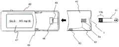
图15示出图9和图10的血糖值测定器等的生物试样测定装置的变形例,表示包含具有显示单元47的测定装置主体40、以及覆盖测定装置主体40的一部分的罩41的生物试样测定装置。在罩41中设有用于插入生物试样测定传感器11的传感器插入单元1,进而在罩41的背面上设有加速度传感器5a。FIG. 15 shows a modified example of a biological sample measuring device such as the blood glucose level measuring device shown in FIG. 9 and FIG. Sample measuring device. The
在罩41安装在测定装置主体40上时,设置在罩41的背面的加速度传感器5a经由导线42、连接部43、测定装置主体的连接部44而与装载在测定装置主体40内部的控制单元等电子电路电连接。由此,若在装置主体40安装罩41,则从装置主体40经由连接单元44等而对加速度传感器5a提供电源,另外,能够将来自加速度传感器5a的信号也发送到装置主体40侧。When the
另外,通过接触到生物试样测定传感器11的连接电极单元11b(与用于测定的检测电极即作用极、对极等连接)、配置在测定装置主体40的传感器接触部46上的多个接触片45,从而生物试样测定传感器11与测定装置主体40内的测定单元等电子电路电连接。In addition, through contact with the
在图15所示的生物试样测定装置中,在可更换的罩41上设置加速度传感器5a,从而能够通过更换罩41来使用灵敏度不同的加速度传感器。也可以在测定装置主体40的基板4上设置另一个加速度传感器5b(未图示)。通过改变两个加速度传感器5a、5b的灵敏度,能够检测不同大小的冲击。因此,能够以高灵敏度检测触碰到生物试样测定传感器11的冲击,使测定时的检测性能提高,实现可靠性更高的测定以及可靠性高的测定装置。In the biological sample measurement device shown in FIG. 15 , the
[实施方式8][Embodiment 8]
在对生物试样测定传感器11的生物试样的点滴量过少时,无法进行适当的生物成分量的测定(例如血糖值测定等)。在该情况下,有时在对生物试样进行追加点滴(也称为“追加补充”)后进行测定。因此,在判断为生物试样的点滴量过少后,有时需要以预定的时间等待到接受追加点滴为止。图16示出通过加速度传感器5a等检测是否进行了作为该追加点滴的“追加补充”的动作流程。在图16所示的动作流程中,以配置在传感器插入单元1上的加速度传感器5a(参照图11等)检测追加补充。以下,对各步骤S21~S33具体地说明。When the amount of the biological sample applied to the biological
S21:确认生物试样测定传感器11的安装。通过确认与生物试样测定传感器11的连接电极单元11b(参照图12等)接触的测定装置侧的接触单元16a(多个接触片20;参照图9、图15等)的端子间的导通/电阻值来确认生物试样测定传感器11是否安装在传感器插入单元1上(参照图11等)。若能够确认生物试样测定传感器11的安装,则转移到步骤S22。S21: Confirm installation of the biological
S22:确认生物试样测定传感器11的安装后,测定装置的主电源接通。由此,显示单元3(参照图1等)等能够进行显示。此外,通过按压位于测定装置上的电源按钮,也能够使主电源接通。S22: After confirming the attachment of the biological
S23:判别所安装的生物试样测定传感器11的机种。基于设置在生物试样测定传感器11的连接电极部11b上的图案的不同等进行机种判别。S23: Discriminate the model of the attached biological
S24:在判别出的机种不适当时,转移到步骤S25;若判别出的机种适当,则转移到步骤S26。S24: When the determined model is not suitable, transfer to step S25; if the determined model is suitable, transfer to step S26.
S25:显示机种错误(图中为“E7”的错误码),进行指示以将生物试样测定传感器11更换为正确的传感器。然后,转移到S21。S25: A model error is displayed (error code "E7" in the figure), and an instruction is given to replace the biological
S26:进行提醒“血液的点滴”的显示,对用户提醒对生物试样测定传感器11进行点滴。S26 : A reminder "infusion of blood" is displayed, and the user is reminded to instill the biological
S27:判别血液是否点滴到生物试样测定传感器11的点滴单元11a。通过在血液的流入方向预先设置多个“检测极”,利用血液的流入检测该检测极的电极间的电阻值等的变化来进行血液点滴的确认。例如,首先用离生物试样测定传感器11的点滴单元11a最近的第一检测极检测血液的点滴。若确认了血液的点滴,则转移到步骤S28。S27: It is judged whether or not blood has been spotted on the
也能够用加速度传感器5a(参照图11等)间接地检测血液的点滴。即,在将用户的手指渗出的血液点滴到生物试样测定传感器11的前端的点滴部11a时,手指自然接触到生物试样测定传感器11。能够用加速度传感器5a检测该接触。此时,只要能够检测手指和生物试样测定传感器11发生接触即可。The dripping of blood can also be detected indirectly by the
用于点滴血液的、手指接触到生物试样测定传感器11的点滴部11a的接触方式因用户而异,既有使手指用力压靠的用户,也有使手指轻轻接触的用户。因此,检测手指与生物试样测定传感器11的接触的阈值L4优选预先设为小于判断测定中的冲击的阈值L2。设为L4≤L2即可,但优选为L4=α*L2(α=1/1~1/10左右)。作为阈值L4,例如为0.005~0.3g左右即可。The manner in which the finger touches the
S28:利用第二检测极(离点滴部11a最远位置的检测极),检测血液是否充分流入传感器11a的毛细管(供给路径;未图示)。若检测到血液的流入,则判断为测定所需要的足够量的血液流入到生物试样测定传感器11的毛细管(供给路径),转移到步骤S33。另一方面,在判断为血液的流入不充分的情况下,转移到步骤S29。优选第二检测极配置在离点滴单元11a最远的位置,但配置在比检测氧化还原反应电流的作用极、对极等检测电极更靠毛细管的深处(比点滴单元11a远的一侧)即可。S28: Using the second detection electrode (the detection electrode at the farthest position from the
S29:在生物试样的追加点滴(追加补充)顺序中,设定直到等待完成“追加补充(追加点滴)”为止的时间(追加补充等待时间)。追加补充等待时间为例如10秒~120秒左右,优选为15~60秒。S29 : In the sequence of additional infusion (additional infusion) of the biological sample, the time until the completion of "additional infusion (additional infusion)" is set (additional replenishment waiting time). The additional replenishment waiting time is, for example, about 10 seconds to 120 seconds, preferably 15 to 60 seconds.
S30:在监视追加补充等待时间,超过了等待时间的情况下,判断为“点滴不良”/“点滴量不足”引起的错误。然后,在显示单元3上显示错误和通过发声器发出注意音,提醒更换生物试样测定传感器11重新测定。S30: When monitoring the waiting time for additional supplementation, and exceeding the waiting time, it is judged as an error due to "defective drip"/"insufficient drip volume". Then, an error is displayed on the
S31:由加速度传感器5a(参照图11等)检测用户的手指是否接触到点滴单元11a,并判断是否对生物试样测定传感器11追加点滴。基本上与步骤S27同样,对于阈值L4的设定也是同样的。若检测到进行了追加点滴,则转移到步骤S32。在无法检测的情况下,返回到步骤S30。S31: Detect whether the user's finger is in contact with the
S32:与上述步骤S28同样,根据距点滴单元11a最远的位置(最深处)的第二检测极和预定电极的电阻值等的变化来检测血液的流入。若检测到血液,则认为在测定所需的足够的血液流入到了生物试样测定传感器11的毛细管(供给路径),转移到步骤S33。在判断为血液不充分的情况下,返回到步骤S30。S32: Similar to the above step S28, blood inflow is detected based on changes in the resistance values of the second detection electrode and the predetermined electrode at the farthest position (the deepest part) from the
S33:若点滴量(作为试样的血液等的量)足够而判断为能够进行测定,则进行“点滴完成”的显示,进行血糖值的测定处理。S33: If the amount of infusion (the amount of blood as a sample, etc.) is sufficient and it is determined that the measurement can be performed, "infusion complete" is displayed, and the blood sugar level measurement process is performed.
工业实用性Industrial Applicability
如上述那样,本发明生物试样测定装置,包括具有传感器插入单元的主体外壳、连接到传感器插入单元的测定单元、连接到测定单元的控制单元、以及连接到控制单元的显示部,并设有用于检测对所述传感器插入单元施加的冲击的加速度传感器,因此能够提高测定值的可靠性,并提高测定精度。As described above, the biological sample measurement device of the present invention includes a main body case having a sensor insertion unit, a measurement unit connected to the sensor insertion unit, a control unit connected to the measurement unit, and a display unit connected to the control unit, and is provided with Since the acceleration sensor is used to detect the impact applied to the sensor insertion unit, the reliability of the measured value can be improved, and the measurement accuracy can be improved.
即,在本发明中,加速度传感器检测例如通过生物试样测定传感器对传感器插入单元施加的冲击。若利用该加速度传感器检测到的冲击超过预定值,则认为通过测定单元测定出的测定结果并不适当,从而能够不显示测定值,在显示单元上显示测定不适当。因此,防止显示可靠性存在问题的不适当的测定结果,实现测定精度的提高。因此,能够期待作为测定血糖值、乳酸值等的生物试样测定装置的灵活运用。That is, in the present invention, the acceleration sensor detects, for example, an impact applied to the sensor insertion unit by the biological sample measurement sensor. If the impact detected by the acceleration sensor exceeds a predetermined value, the measurement result measured by the measurement unit is deemed to be inappropriate, and the measurement value may not be displayed, and the measurement may be displayed on the display unit as inappropriate. Therefore, it is possible to prevent inappropriate measurement results showing reliability problems, and to improve measurement accuracy. Therefore, it can be expected to be utilized as a biological sample measuring device for measuring blood sugar levels, lactic acid levels, and the like.
Claims (10)
Translated fromChineseApplications Claiming Priority (3)
| Application Number | Priority Date | Filing Date | Title |
|---|---|---|---|
| JP2011069226 | 2011-03-28 | ||
| JP2011-069226 | 2011-03-28 | ||
| PCT/JP2012/002155WO2012132432A1 (en) | 2011-03-28 | 2012-03-28 | Device for measuring biological sample |
Publications (2)
| Publication Number | Publication Date |
|---|---|
| CN103354901Atrue CN103354901A (en) | 2013-10-16 |
| CN103354901B CN103354901B (en) | 2015-09-09 |
Family
ID=46930204
Family Applications (1)
| Application Number | Title | Priority Date | Filing Date |
|---|---|---|---|
| CN201280006779.7AActiveCN103354901B (en) | 2011-03-28 | 2012-03-28 | Biological sample measuring device |
Country Status (5)
| Country | Link |
|---|---|
| US (1) | US8834691B2 (en) |
| EP (2) | EP2693208B1 (en) |
| JP (3) | JP5798618B2 (en) |
| CN (1) | CN103354901B (en) |
| WO (1) | WO2012132432A1 (en) |
Families Citing this family (20)
| Publication number | Priority date | Publication date | Assignee | Title |
|---|---|---|---|---|
| US7925449B2 (en)* | 2006-09-18 | 2011-04-12 | Cfph, Llc | Products and processes for analyzing octane content |
| WO2012132432A1 (en)* | 2011-03-28 | 2012-10-04 | パナソニック株式会社 | Device for measuring biological sample |
| JP5749806B2 (en)* | 2011-11-01 | 2015-07-15 | パナソニックヘルスケアホールディングス株式会社 | Biological sample measuring device |
| JP6220170B2 (en)* | 2012-07-12 | 2017-10-25 | パナソニックヘルスケアホールディングス株式会社 | Liquid sample measuring device |
| WO2014099419A1 (en)* | 2012-12-17 | 2014-06-26 | Abbott Point Of Care Inc | A portable clinical analysis system for hematocrit measurement |
| CN104956212B (en) | 2012-12-17 | 2017-10-27 | 雅培医护站股份有限公司 | Self-correction of spatial orientation and motion of a portable clinical testing device |
| WO2014099420A1 (en) | 2012-12-17 | 2014-06-26 | Abbott Point Of Care Inc | A portable clinical analysis system for immunometric measurement |
| EP2932259B1 (en) | 2012-12-17 | 2019-11-13 | Abbott Point Of Care, Inc. | Spatial orientation determination in portable clinical analysis systems |
| WO2014099421A1 (en) | 2012-12-17 | 2014-06-26 | Abbott Point Of Care Inc | Operation and verification of a portable clinical analysis system |
| US9623409B2 (en) | 2013-03-11 | 2017-04-18 | Cue Inc. | Cartridges, kits, and methods for enhanced mixing for detection and quantification of analytes |
| US10545161B2 (en) | 2013-03-11 | 2020-01-28 | Cue Health Inc. | Systems and methods for detection and quantification of analytes |
| KR102557135B1 (en) | 2013-03-11 | 2023-07-19 | 큐 헬스 인코퍼레이티드 | Systems and methods for detection and quantification of analytes |
| USD745423S1 (en) | 2014-05-12 | 2015-12-15 | Cue Inc. | Automated analyzer test cartridge and sample collection device for analyte detection |
| US20150330937A1 (en)* | 2014-05-16 | 2015-11-19 | Lifescan Scotland Limited | Hand-held test meter with body portion proximity sensor module |
| USD742524S1 (en)* | 2014-11-17 | 2015-11-03 | Bayer Healthcare Llc | Analyte meter |
| AU2016296589B2 (en) | 2015-07-17 | 2021-11-18 | Cue Health Inc. | Systems and methods for enhanced detection and quantification of analytes |
| WO2018140540A1 (en) | 2017-01-25 | 2018-08-02 | Cue Health Inc. | Systems and methods for enhanced detection and quantification of analytes |
| WO2018148312A1 (en)* | 2017-02-07 | 2018-08-16 | Colorado State University Research Foundation | Handheld electrochemical sensing platform |
| US11408881B2 (en) | 2017-05-04 | 2022-08-09 | Roche Diabetes Care, Inc. | Test meter and method for detecting undue pressure applied to an inserated test strip |
| JP7572607B2 (en)* | 2020-09-02 | 2024-10-24 | 東亜ディーケーケー株式会社 | Measurement equipment |
Citations (3)
| Publication number | Priority date | Publication date | Assignee | Title |
|---|---|---|---|---|
| JP2000283789A (en)* | 1999-03-30 | 2000-10-13 | Yamasa Tokei Keiki Kk | Pedometer |
| WO2010052849A1 (en)* | 2008-11-04 | 2010-05-14 | パナソニック株式会社 | Measurement device, insulin infusion device, measurement method, method for controlling insulin infusion device, and program |
| JP2010266217A (en)* | 2009-05-12 | 2010-11-25 | Panasonic Corp | Portable blood glucose level measuring device |
Family Cites Families (10)
| Publication number | Priority date | Publication date | Assignee | Title |
|---|---|---|---|---|
| US20060091006A1 (en)* | 1999-11-04 | 2006-05-04 | Yi Wang | Analyte sensor with insertion monitor, and methods |
| EP2388587B1 (en) | 2000-11-30 | 2018-01-10 | Panasonic Healthcare Holdings Co., Ltd. | Method of quantifying substrate |
| EP1382968B1 (en)* | 2002-07-18 | 2008-11-19 | Panasonic Corporation | Measuring apparatus with a biosensor |
| US7132041B2 (en)* | 2003-02-11 | 2006-11-07 | Bayer Healthcare Llc | Methods of determining the concentration of an analyte in a fluid test sample |
| EP3553510B1 (en)* | 2006-05-03 | 2024-12-18 | Ascensia Diabetes Care Holdings AG | Underfill detection system for a biosensor |
| US20080125700A1 (en)* | 2006-11-29 | 2008-05-29 | Moberg Sheldon B | Methods and apparatuses for detecting medical device acceleration, temperature, and humidity conditions |
| JP4825762B2 (en)* | 2006-12-20 | 2011-11-30 | 株式会社タニタ | Test solution measuring apparatus and sensitivity calibration method |
| WO2008120614A1 (en)* | 2007-03-30 | 2008-10-09 | Terumo Kabushiki Kaisha | Humor ingredient measuring apparatus |
| JP2010063576A (en)* | 2008-09-10 | 2010-03-25 | Panasonic Corp | Blood inspection apparatus |
| WO2012132432A1 (en)* | 2011-03-28 | 2012-10-04 | パナソニック株式会社 | Device for measuring biological sample |
- 2012
- 2012-03-28WOPCT/JP2012/002155patent/WO2012132432A1/enactiveApplication Filing
- 2012-03-28JPJP2013507185Apatent/JP5798618B2/enactiveActive
- 2012-03-28USUS14/001,954patent/US8834691B2/enactiveActive
- 2012-03-28EPEP12765681.7Apatent/EP2693208B1/enactiveActive
- 2012-03-28CNCN201280006779.7Apatent/CN103354901B/enactiveActive
- 2012-03-28EPEP17188359.8Apatent/EP3270147B1/enactiveActive
- 2015
- 2015-08-20JPJP2015162793Apatent/JP6000418B2/enactiveActive
- 2016
- 2016-08-29JPJP2016167037Apatent/JP6209657B2/enactiveActive
Patent Citations (3)
| Publication number | Priority date | Publication date | Assignee | Title |
|---|---|---|---|---|
| JP2000283789A (en)* | 1999-03-30 | 2000-10-13 | Yamasa Tokei Keiki Kk | Pedometer |
| WO2010052849A1 (en)* | 2008-11-04 | 2010-05-14 | パナソニック株式会社 | Measurement device, insulin infusion device, measurement method, method for controlling insulin infusion device, and program |
| JP2010266217A (en)* | 2009-05-12 | 2010-11-25 | Panasonic Corp | Portable blood glucose level measuring device |
Also Published As
| Publication number | Publication date |
|---|---|
| JP2015206804A (en) | 2015-11-19 |
| JP6000418B2 (en) | 2016-09-28 |
| JP6209657B2 (en) | 2017-10-04 |
| WO2012132432A1 (en) | 2012-10-04 |
| CN103354901B (en) | 2015-09-09 |
| EP2693208A1 (en) | 2014-02-05 |
| EP3270147A1 (en) | 2018-01-17 |
| US20130334041A1 (en) | 2013-12-19 |
| US8834691B2 (en) | 2014-09-16 |
| JPWO2012132432A1 (en) | 2014-07-24 |
| EP2693208B1 (en) | 2017-10-11 |
| JP2017021038A (en) | 2017-01-26 |
| JP5798618B2 (en) | 2015-10-21 |
| EP2693208A4 (en) | 2014-08-13 |
| EP3270147B1 (en) | 2023-08-02 |
Similar Documents
| Publication | Publication Date | Title |
|---|---|---|
| CN103354901B (en) | Biological sample measuring device | |
| TW201402072A (en) | Battery status detection and storage method and system in medical monitoring | |
| TWI412744B (en) | Measuring device | |
| KR20140130039A (en) | Analyte meter test strip detection | |
| TW201510522A (en) | Analyte meter digital sample detection | |
| EP3076174B1 (en) | Analyte meter with contoured strip port to improve electrochemical test strip reliability | |
| CN101040185B (en) | Contact connector assembly for a sensor-dispensing instrument | |
| JP5212990B2 (en) | Analysis equipment | |
| EP2816349B1 (en) | Orientation independent meter | |
| JP6484315B2 (en) | Liquid sample measuring device | |
| JP4345888B2 (en) | Measurement display | |
| JP2006015068A (en) | Biological information measuring sensor and biological information measuring apparatus | |
| JP2000116626A (en) | Body fluid measuring device and body | |
| US11408881B2 (en) | Test meter and method for detecting undue pressure applied to an inserated test strip | |
| JP2000116626A5 (en) | ||
| JP2012177677A (en) | Analyzer | |
| JP2014165896A (en) | Mobile terminal | |
| US20250176893A1 (en) | Biological information detection system | |
| KR20180038619A (en) | Apparatus for measuring biometrics with cartridge type | |
| JP2025090005A (en) | Biometric information detection system | |
| JP3117358U (en) | Biological measuring instrument test piece having identification function and measuring instrument | |
| JP2016085135A (en) | Blood sugar measurement device and method for controlling the device | |
| CN112839128A (en) | mobile terminal | |
| CN104185445A (en) | Testing member cartridge | |
| JP2009276253A (en) | Hand-held body fluid meter |
Legal Events
| Date | Code | Title | Description |
|---|---|---|---|
| C06 | Publication | ||
| PB01 | Publication | ||
| C10 | Entry into substantive examination | ||
| SE01 | Entry into force of request for substantive examination | ||
| ASS | Succession or assignment of patent right | Owner name:PANASONIC HEALTHCARE + MEDICAL EQUIPMENT CO., LTD. Free format text:FORMER OWNER: MATSUSHITA ELECTRIC INDUSTRIAL CO, LTD. Effective date:20140421 | |
| C41 | Transfer of patent application or patent right or utility model | ||
| TA01 | Transfer of patent application right | Effective date of registration:20140421 Address after:Ehime Prefecture, Japan Applicant after:Panasonic Healthcare Co., Ltd Address before:Osaka Japan Applicant before:Matsushita Electric Industrial Co., Ltd. | |
| ASS | Succession or assignment of patent right | Owner name:PANASONIC HEALTHCARE HOLDINGS CO., LTD. Free format text:FORMER OWNER: PANASONIC HEALTHCARE + MEDICAL EQUIPMENT CO., LTD. Effective date:20150112 | |
| C41 | Transfer of patent application or patent right or utility model | ||
| TA01 | Transfer of patent application right | Effective date of registration:20150112 Address after:Tokyo, Japan, Japan Applicant after:Panasonic's health medical treatment is controlled interest Co., Ltd. Address before:Ehime Prefecture, Japan Applicant before:Panasonic Healthcare Co., Ltd | |
| C14 | Grant of patent or utility model | ||
| GR01 | Patent grant | ||
| CP01 | Change in the name or title of a patent holder | Address after:Tokyo, Japan, Japan Patentee after:Pu Hei holding company Address before:Tokyo, Japan, Japan Patentee before:Panasonic's health medical treatment is controlled interest Co., Ltd. | |
| CP01 | Change in the name or title of a patent holder |