CN103354187A - Key and keyboard - Google Patents
Key and keyboardDownload PDFInfo
- Publication number
- CN103354187A CN103354187ACN2013101992635ACN201310199263ACN103354187ACN 103354187 ACN103354187 ACN 103354187ACN 2013101992635 ACN2013101992635 ACN 2013101992635ACN 201310199263 ACN201310199263 ACN 201310199263ACN 103354187 ACN103354187 ACN 103354187A
- Authority
- CN
- China
- Prior art keywords
- button
- keycap
- plate
- buckle
- connecting rod
- Prior art date
- Legal status (The legal status is an assumption and is not a legal conclusion. Google has not performed a legal analysis and makes no representation as to the accuracy of the status listed.)
- Pending
Links
Images


Landscapes
- Push-Button Switches (AREA)
Abstract
Description
Translated fromChinese技术领域technical field
本发明关于一种按键及键盘,尤指一种薄型化的按键及键盘。The present invention relates to a button and a keyboard, in particular to a thinned button and keyboard.
背景技术Background technique
就目前个人电脑的使用习惯而言,键盘为不可或缺的输入设备之一,用以输入文字、符号或数字。近来,由于电子产品皆朝向轻薄的方向发展,故配置于该电子产品的键盘亦朝向薄型化的趋势发展。然而,习知的键盘内部设置有许多机构件,例如剪刀脚机构(plunger)、圆顶橡胶(rubber dome)、平衡杆(linkbar)等,其占据一定按键内部的机构空间,进而限制按键的高度,故而不利于按键及键盘朝薄型化的趋势发展,因此如何设计出薄型化的按键及键盘便成为设计人员所需挑战的课题。As far as current personal computer usage habits are concerned, the keyboard is one of the indispensable input devices for inputting characters, symbols or numbers. Recently, since the electronic products are all developing toward thinner and lighter, the keyboards configured on the electronic products are also developing toward thinner and thinner. However, there are many mechanical components inside the known keyboard, such as a plunger, a rubber dome, a linkbar, etc., which occupy a certain amount of space inside the key, thereby limiting the height of the key. , so it is not conducive to the development of thinner buttons and keyboards. Therefore, how to design thinner buttons and keyboards has become a challenge for designers.
发明内容Contents of the invention
本发明提供一种薄型化的按键及键盘,以解决上述问题。The invention provides a thin keypad and keyboard to solve the above problems.
为了达成上述目的,本发明揭露一种按键,其设置于键盘的底板上,该按键包含有:键帽、连接杆件、卡扣端板以及承载凹部。该键帽设置于该底板上方;该连接杆件连接该键帽与该底板;该卡扣端板连接于该底板,该卡扣端板上形成有滑槽,该连接杆件的一端部可滑动地卡扣于该滑槽内;该承载凹部形成于该底板上且邻接于该滑槽,该承载凹部的承载面与该底板的顶面相距一断差,该连接杆件的该端部于可滑动地卡扣于该滑槽内时陷入该承载凹部内且承靠于该承载凹部的该承载面。In order to achieve the above purpose, the present invention discloses a button, which is disposed on the bottom plate of the keyboard, and the button includes: a keycap, a connecting rod, a buckle end plate, and a bearing recess. The key cap is arranged above the base plate; the connecting rod connects the key cap and the base plate; Slidingly buckled in the chute; the bearing recess is formed on the base plate and adjacent to the chute, the bearing surface of the bearing recess is separated from the top surface of the base plate by a gap, and the end of the connecting rod When being slidably buckled in the chute, it sinks into the carrying recess and leans against the carrying surface of the carrying recess.
作为可选技术方案,该卡扣端板包含有卡扣板体;以及连接板体,其连接于该卡扣板体的一侧与该底板的边缘,其中该滑槽形成于该卡扣板体与该连接板体且邻接该承载凹部。As an optional technical solution, the buckle end plate includes a buckle plate body; and a connecting plate body, which is connected to one side of the buckle plate body and the edge of the bottom plate, wherein the chute is formed on the buckle plate The body and the connecting plate body are adjacent to the bearing recess.
作为可选技术方案,该卡扣板体垂直于该连接板体。As an optional technical solution, the buckling board is perpendicular to the connecting board.
作为可选技术方案,该卡扣端板另包含有延伸板体,其延伸于该卡扣板体的另一侧,该延伸板体与该承载凹部共同用来防止该连接杆件的该端部翻转。As an optional technical solution, the buckle end plate further includes an extension plate, which extends on the other side of the buckle plate, and the extension plate and the bearing recess are used together to prevent the end of the connecting rod from side flipped.
作为可选技术方案,该延伸板体垂直于该卡扣板体。As an optional technical solution, the extension board is perpendicular to the buckle board.
作为可选技术方案,该底板上形成有开口,其邻接于该承载凹部,且该开口与该滑槽位于该承载凹部的相对两侧。As an optional technical solution, an opening is formed on the bottom plate, which is adjacent to the carrying recess, and the opening and the slide groove are located on opposite sides of the carrying recess.
作为可选技术方案,该断差等于0.1厘米。As an optional technical solution, the gap is equal to 0.1 cm.
作为可选技术方案,所述的按键另包含有:枢接结构,其设置于该键帽上,该枢接结构用来使该键帽枢接于该连接杆件的一侧边部,以使该键帽于该连接杆件的该端部于该滑槽内滑动时,能被该连接杆件的该侧边部带动而接近或远离该底板。As an optional technical solution, the key further includes: a pivot structure, which is arranged on the keycap, and the pivot structure is used to pivotally connect the keycap to one side of the connecting rod, so as to When the end portion of the connecting rod slides in the slide groove, the keycap can be driven by the side portion of the connecting rod to approach or move away from the bottom plate.
作为可选技术方案,所述的按键另包含有:升降支撑机构,其设置于该底板与该键帽的间,该升降支撑机构用来带动该键帽相对该底板升降。As an optional technical solution, the key further includes: a lifting support mechanism, which is arranged between the bottom plate and the keycap, and the lifting support mechanism is used to drive the keycap to lift relative to the bottom plate.
作为可选技术方案,该承载凹部以冲压成型的方式形成于该底板上。As an optional technical solution, the bearing recess is formed on the bottom plate by stamping.
根据另一具体实施方式,本发明提供一种键盘,其包含有至少一按键,该至少一按键为上述的按键。According to another specific embodiment, the present invention provides a keyboard, which includes at least one key, and the at least one key is the above-mentioned key.
综上所述,本发明利用形成于底板上的承载凹部以及承载凹部的承载面与底板的顶面具有断差的结构设计,使得当连接杆件的端部组装至卡扣端板后,连接杆件的端部可陷入承载凹部内而造成连接杆件整体朝底板靠近约断差的距离。再者,因连接杆件连接键帽上与底板,故键帽亦可被连接杆件带动而朝底板靠近约断差的距离,如此按键的整体高度便可下降,进而有利于按键及键盘朝向薄型化的趋势发展。有关本发明的前述及其他技术内容、特点与功效,在以下配合参考图式的实施例的详细说明中,将可清楚的呈现。In summary, the present invention utilizes the load-bearing recess formed on the bottom plate and the structural design that the load-bearing surface of the load-bearing recess has a gap with the top surface of the bottom plate, so that when the end of the connecting rod is assembled to the buckle end plate, the connection The ends of the rods can sink into the bearing recesses so that the entire connecting rods approach the bottom plate by a distance of about a break. Furthermore, because the connecting rod connects the top of the keycap and the bottom plate, the keycap can also be driven by the connecting rod to approach the bottom plate by a distance of about a break, so that the overall height of the key can be reduced, which is beneficial to the orientation of the key and the keyboard. The trend of thinning is developing. The aforementioned and other technical contents, features and effects of the present invention will be clearly presented in the following detailed description of the embodiments with reference to the drawings.
附图说明Description of drawings
图1为本发明实施例键盘的元件示意图。FIG. 1 is a schematic diagram of components of a keyboard according to an embodiment of the present invention.
图2为本发明实施例按键的部分元件示意图。FIG. 2 is a schematic diagram of some components of the button according to the embodiment of the present invention.
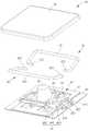
图3为本发明实施例按键的部分元件爆炸示意图。Fig. 3 is an exploded schematic diagram of some components of the button according to the embodiment of the present invention.
图4为本发明实施例按键于另一视角的部分元件爆炸示意图。FIG. 4 is an exploded schematic view of some components of the button according to another viewing angle of the embodiment of the present invention.
图5为图2所示按键沿剖面线X-X的元件剖面示意图。FIG. 5 is a schematic cross-sectional view of the key shown in FIG. 2 along the section line X-X.
图6为本发明实施例按键于另一视角的元件示意图。FIG. 6 is a schematic diagram of the components of the button according to another viewing angle of the embodiment of the present invention.
图7为本发明实施例卡扣端板与底板的元件部分示意图。Fig. 7 is a schematic diagram of parts of components of the fastening end plate and the bottom plate according to the embodiment of the present invention.
具体实施方式Detailed ways
以下实施例中所提到的方向用语,例如:上、下、左、右、前或后等,仅是参考附加图式的方向。因此,使用的方向用语是用来说明并非用来限制本发明。请参阅图1,图1为本发明实施例键盘3的元件示意图。如图1所示,键盘3包含有底板30、电路板32以及复数个按键34,电路板32以及复数个按键34皆设置于底板30上,且复数个按键34可供使用者按压,藉以触发电路板32以执行使用者所欲进行的操作,例如输入文字、符号或数字等。The directional terms mentioned in the following embodiments, such as: up, down, left, right, front or back, etc., are only directions referring to the attached drawings. Accordingly, the directional terms are used to illustrate and not to limit the invention. Please refer to FIG. 1 . FIG. 1 is a schematic diagram of components of a keyboard 3 according to an embodiment of the present invention. As shown in Figure 1, the keyboard 3 includes a
请参阅图2至图5,图2为本发明实施例按键34的部分元件示意图,图3为本发明实施例按键34的部分元件爆炸示意图,图4为本发明实施例按键于另一视角的部分元件爆炸示意图,图5为图2所示按键沿剖面线X-X的元件剖面示意图。如图2至图5所示,按键34包含有键帽36以及弹性件38,键帽36设置于底板30上方,且弹性件38设置于底板30与键帽36之间。当使用者按压按键34时,键帽36朝底板30移动而压缩弹性件38。此时,弹性件38因弹性变形而储存弹性位能。当使用者完成按压时,使用者的手指离开键帽36,此时弹性件38便可释放该弹性位能而施予键帽36弹性回复力,藉以驱动键帽36复位。Please refer to FIG. 2 to FIG. 5, FIG. 2 is a schematic diagram of some components of the
于此实施例中,弹性件38可为圆顶橡胶(rubber dome),但不受此限,例如弹性件38亦可为金属簧片。至于采用上述何者设计,其端视实际需求而定。此外,电路板32包含有对应各按键34的开关321,且弹性件38对应开关321处具有触发部381。当使用者按压按键34时,弹性件38被压缩而使其触发部381按压电路板32的开关321,藉以执行相对应的一按键指令,例如输入文字、符号或数字等。于此实施例中,电路板32可为薄膜电路板(membrane),但不受此限,例如电路板32亦可为一般具有触发开关的按键电路板。至于采用上述何者设计,其端视实际需求而定。In this embodiment, the
除此之外,按键34包含有升降支撑机构40,其设置于底板30与键帽36之间。当使用者按压按键34时,升降支撑机构40可将使用者的按压力平均分配给键帽36,以使键帽36可平稳地相对底板30向下运动,藉以稳定地触发开关321而执行该按键指令。当键帽36于上述的复位过程中,升降支撑机构40可将弹性件38所产生的该弹性回复力平均分配给键帽36,以使键帽36可平稳地相对底板30向上运动。换句话说,升降支撑机构40可用来带动键帽36平稳地相对底板30升降,以使键帽36于升降过程中保持平稳,有助于按键34作动的稳定度。In addition, the
如图2至图5所示,按键34另包含有至少一连接杆件42以及两卡扣端板44。连接杆件42用来连接键帽36与底板30,且卡扣端板44连接于底板30。请参阅图3至图7,图6为本发明实施例按键34于另一视角的元件示意图,图7为本发明实施例卡扣端板44与底板30的元件部分示意图。如图3至图7所示,卡扣端板44上形成有至少一滑槽441,按键34另包含有复数个枢接结构46,其设置于键帽36上,且复数个枢接结构46用来将键帽36枢接于各连接杆件42的一侧边部421。于组装连接杆件42时,可将各连接杆件42的一端部423可滑动地卡扣于对应的滑槽441内,且另将各连接杆件42的侧边部421枢接于对应的枢接结构46。As shown in FIGS. 2 to 5 , the
于此实施例中,按键34可包含有两个连接杆件42,且各卡扣端板44上可形成有两个滑槽441,各连接杆件42的侧边部421及端部423分别安装于对应的枢接结构46及滑槽441内,而连接杆件42及各卡扣端板44上的滑槽441数量可不局限于此实施例图式所绘示,例如按键34亦可仅包含有一个连接杆件42,且各卡扣端板44上亦可对应地仅形成有一个滑槽441。换句话说,只要是按键34包含有一个以上的连接杆件42以及卡扣端板44上形成有一个以上的滑槽441的结构设计,均在本发明所保护的范畴内。In this embodiment, the
如图5所示,当键帽36被按压时,两连接杆件42的端部423可朝彼此靠近的方向相对滑槽441滑动,且两连接杆件42的侧边部421可于对应的枢接结构46内枢转,此时键帽36便可被两连接杆件42的侧边部421带动而接近底板30。此外,当使用者按压按键34时,两连接杆件42可与升降支撑机构40共同将使用者的按压力平均分配给键帽36,以使键帽36可更平稳地相对底板30向下运动,藉以稳定地触发电路板32的开关321而执行该按键指令。As shown in FIG. 5 , when the
同理,当键帽36被释放时,弹性件38释放该弹性位能而施予键帽36该弹性回复力,藉以驱动键帽36复位。当键帽36于上述的复位过程中,两连接杆件42的端部423可朝彼此远离的方向相对滑槽441滑动,且两连接杆件42的侧边部421可于对应的枢接结构46内枢转,此时键帽36便可被两连接杆件42的侧边部421带动而远离底板30。此外,当键帽36于上述的复位过程中,两连接杆件42可与升降支撑机构40共同将弹性件38所产生的该弹性回复力平均分配给键帽36,以使键帽36可平稳地相对底板30向上运动。换句话说,连接杆件42亦可用来驱动键帽36平稳地接近或远离底板30,以使键帽36于升降过程中保持平稳,有利于按键34作动时的稳定度。Similarly, when the
如图3、图6以及图7所示,卡扣端板44包含有卡扣板体443以及连接板体445,连接板体445连接于卡扣板体443的一侧与底板30的一边缘。于此实施例中,卡扣板体443可实质上垂直于连接板体445,且滑槽441形成于卡扣板体443与连接板体445上。此外,卡扣端板44可另包含有延伸板体447,其延伸于卡扣板体443的另一侧。于此实施例中,延伸板体447可实质上垂直于卡扣板体443,亦即延伸板体447可平行于连接板体445。于实际应用上,卡扣板体443、连接板体445以及延伸板体447可以冲压成型的方式一体成型。值得一提的是,延伸板体447为一可省略的结构,亦即本发明的卡扣端板44可仅包含有卡扣板体443与连接板体445而不包含有延伸板体447,藉以简化卡扣端板44的制造过程。As shown in FIG. 3 , FIG. 6 and FIG. 7 , the
除此之外,按键34另包含有承载凹部48,其形成于底板30上,且承载凹部48邻接于卡扣板体443与连接板体445上的滑槽441。另外,承载凹部48的承载面481与底板30的顶面301相距一断差S(如图6以及图7所示),因此当连接杆件42的端部423可滑动地卡扣于卡扣板体443与连接板体445上的滑槽441内时,连接杆件42的端部423陷入承载凹部48内且承靠于承载凹部48的承载面481。如此一来,承载凹部48的承载面481便可与卡扣端板44的延伸板体447共同防止连接杆件42的端部423翻转,以使连接杆件42的端部423能稳定地于滑槽441内滑动。In addition, the
进一步地,由于承载凹部48的承载面481与底板30的顶面301相距断差S,当连接杆件42的端部423陷入承载凹部48内且承靠于承载凹部48的承载面481时,连接杆件42便可自底板30的顶面301下降断差S。也就是说,于连接杆件42的端部423组装至卡扣端板44后,连接杆件42的端部423因陷入底板30上的承载凹部48而使连接杆件42的侧边部421朝底板30靠近约断差S的距离,而连接杆件42的侧边部421枢接于键帽36上的枢接结构46,故键帽36亦可被连接杆件42的侧边部421带动而朝底板30靠近约断差S的距离,如此按键34的整体高度便可下降,进而有利于按键34及键盘3朝向薄型化发展的趋势。Furthermore, since the bearing
于此实施例中,承载凹部48可以冲压成型的方式形成于底板30上,亦即承载凹部48为在底板30上以冲压成型的方式所形成的打凹结构。于实际应用上,承载凹部48的承载面481与底板30的顶面301相距的断差S实质上等于0.1厘米,但不受此限。此外,底板30上形成有开口303,其邻接于承载凹部48,且开口303与滑槽441位于承载凹部48的相对两侧,于底板30以冲压成型的方式形成承载凹部48的过程中,由于底板30受挤压而凹陷形成承载凹部48,故底板30的材料会向旁侧扩溢,而开口303便可用来提供向旁侧扩溢的底板30的材料一溢料空间,以使承载凹部48能顺利地形成于底板30上。In this embodiment, the carrying
相较于现有技术,本发明利用形成于底板上的承载凹部以及承载凹部的承载面与底板的顶面具有断差的结构设计,使得当连接杆件的端部组装至卡扣端板后,连接杆件的端部可陷入承载凹部内而造成连接杆件整体朝底板靠近约断差的距离。再者,因连接杆件连接键帽与底板,故键帽亦可被连接杆件带动而朝底板靠近约断差的距离,如此按键的整体高度便可下降,进而有利于按键及键盘朝向薄型化的趋势发展。以上所述仅为本发明的较佳实施例,凡依本发明权利要求所做的均等变化与修饰,皆应属本发明的涵盖范围。Compared with the prior art, the present invention utilizes the load-bearing recess formed on the bottom plate and the structural design that the load-bearing surface of the load-bearing recess has a gap with the top surface of the bottom plate, so that when the end of the connecting rod is assembled to the buckle end plate , the end of the connecting rod can sink into the bearing recess, causing the whole connecting rod to approach the bottom plate by a distance of about a break. Furthermore, because the connecting rod connects the keycap and the bottom plate, the keycap can also be driven by the connecting rod to approach the bottom plate by a distance of about a break, so that the overall height of the key can be reduced, which is conducive to the thinning of the key and the keyboard. trend of development. The above descriptions are only preferred embodiments of the present invention, and all equivalent changes and modifications made according to the claims of the present invention shall fall within the scope of the present invention.
Claims (11)
Priority Applications (1)
| Application Number | Priority Date | Filing Date | Title |
|---|---|---|---|
| CN2013101992635ACN103354187A (en) | 2013-05-27 | 2013-05-27 | Key and keyboard |
Applications Claiming Priority (1)
| Application Number | Priority Date | Filing Date | Title |
|---|---|---|---|
| CN2013101992635ACN103354187A (en) | 2013-05-27 | 2013-05-27 | Key and keyboard |
Publications (1)
| Publication Number | Publication Date |
|---|---|
| CN103354187Atrue CN103354187A (en) | 2013-10-16 |
Family
ID=49310542
Family Applications (1)
| Application Number | Title | Priority Date | Filing Date |
|---|---|---|---|
| CN2013101992635APendingCN103354187A (en) | 2013-05-27 | 2013-05-27 | Key and keyboard |
Country Status (1)
| Country | Link |
|---|---|
| CN (1) | CN103354187A (en) |
Cited By (3)
| Publication number | Priority date | Publication date | Assignee | Title |
|---|---|---|---|---|
| CN110648874A (en)* | 2019-08-22 | 2020-01-03 | 苏州达方电子有限公司 | Key and fastening claw structure thereof |
| CN111146033A (en)* | 2019-04-25 | 2020-05-12 | 光宝电子(广州)有限公司 | Key structure and keyboard module |
| CN111933472A (en)* | 2019-09-21 | 2020-11-13 | 光宝电子(广州)有限公司 | Key assembly |
Citations (5)
| Publication number | Priority date | Publication date | Assignee | Title |
|---|---|---|---|---|
| TW408827U (en)* | 1998-12-02 | 2000-10-11 | Chicony Electronics Co Ltd | Push button type balance device |
| TW424923U (en)* | 1999-08-21 | 2001-03-01 | Tsai Jin Shan | Improved press-key structure of keyboard |
| JP2001222925A (en)* | 2001-01-15 | 2001-08-17 | Brother Ind Ltd | Key switch device |
| US20020185364A1 (en)* | 2001-06-07 | 2002-12-12 | Kouki Takahashi | Key switch and keyboard |
| TWM400024U (en)* | 2010-10-22 | 2011-03-11 | Darfon Electronics Corp | Longitudinal keyswitch and keyboard |
- 2013
- 2013-05-27CNCN2013101992635Apatent/CN103354187A/enactivePending
Patent Citations (5)
| Publication number | Priority date | Publication date | Assignee | Title |
|---|---|---|---|---|
| TW408827U (en)* | 1998-12-02 | 2000-10-11 | Chicony Electronics Co Ltd | Push button type balance device |
| TW424923U (en)* | 1999-08-21 | 2001-03-01 | Tsai Jin Shan | Improved press-key structure of keyboard |
| JP2001222925A (en)* | 2001-01-15 | 2001-08-17 | Brother Ind Ltd | Key switch device |
| US20020185364A1 (en)* | 2001-06-07 | 2002-12-12 | Kouki Takahashi | Key switch and keyboard |
| TWM400024U (en)* | 2010-10-22 | 2011-03-11 | Darfon Electronics Corp | Longitudinal keyswitch and keyboard |
Cited By (4)
| Publication number | Priority date | Publication date | Assignee | Title |
|---|---|---|---|---|
| CN111146033A (en)* | 2019-04-25 | 2020-05-12 | 光宝电子(广州)有限公司 | Key structure and keyboard module |
| CN110648874A (en)* | 2019-08-22 | 2020-01-03 | 苏州达方电子有限公司 | Key and fastening claw structure thereof |
| CN110648874B (en)* | 2019-08-22 | 2022-06-10 | 苏州达方电子有限公司 | Button and its claw structure |
| CN111933472A (en)* | 2019-09-21 | 2020-11-13 | 光宝电子(广州)有限公司 | Key assembly |
Similar Documents
| Publication | Publication Date | Title |
|---|---|---|
| US8853580B2 (en) | Key structure of keyboard device | |
| TWM466303U (en) | Keyswitch and keyboard therewith | |
| US8212167B2 (en) | Depressible key structure | |
| CN102623224B (en) | Key | |
| CN105914073B (en) | Button | |
| TW201740412A (en) | Keyswitch | |
| TWM461862U (en) | Keyswitch and keyboard therewith | |
| CN203445039U (en) | Keys and keyboard | |
| CN103681051B (en) | Thin key and keyboard | |
| CN106783318B (en) | Button | |
| TWI674520B (en) | keyboard | |
| TW201839789A (en) | Key structure | |
| CN103354187A (en) | Key and keyboard | |
| CN202662496U (en) | Key and keyboard thereof | |
| TW201721692A (en) | Key structure | |
| US20170062151A1 (en) | Key switch | |
| CN202167386U (en) | Keys and their keyboards | |
| CN201853596U (en) | Keys and keyboards | |
| TWM474242U (en) | Keyswitch and keyboard therewith | |
| US9236206B1 (en) | Thin keyboard command trigger structure | |
| CN109524265B (en) | Push-button | |
| CN201853617U (en) | Keys and keyboards | |
| CN103531391B (en) | Button and keyboard thereof | |
| TWI725651B (en) | Keyswitch | |
| TWM482153U (en) | Keyswitch structure |
Legal Events
| Date | Code | Title | Description |
|---|---|---|---|
| C06 | Publication | ||
| PB01 | Publication | ||
| C10 | Entry into substantive examination | ||
| SE01 | Entry into force of request for substantive examination | ||
| C02 | Deemed withdrawal of patent application after publication (patent law 2001) | ||
| WD01 | Invention patent application deemed withdrawn after publication | Application publication date:20131016 |