CN103347456A - Catheter Systems for Arrhythmia Ablation Therapy - Google Patents
Catheter Systems for Arrhythmia Ablation TherapyDownload PDFInfo
- Publication number
- CN103347456A CN103347456ACN2011800670101ACN201180067010ACN103347456ACN 103347456 ACN103347456 ACN 103347456ACN 2011800670101 ACN2011800670101 ACN 2011800670101ACN 201180067010 ACN201180067010 ACN 201180067010ACN 103347456 ACN103347456 ACN 103347456A
- Authority
- CN
- China
- Prior art keywords
- except
- tissue
- melting
- melt
- guide wire
- Prior art date
- Legal status (The legal status is an assumption and is not a legal conclusion. Google has not performed a legal analysis and makes no representation as to the accuracy of the status listed.)
- Granted
Links
Images


Classifications
- A—HUMAN NECESSITIES
- A61—MEDICAL OR VETERINARY SCIENCE; HYGIENE
- A61B—DIAGNOSIS; SURGERY; IDENTIFICATION
- A61B18/00—Surgical instruments, devices or methods for transferring non-mechanical forms of energy to or from the body
- A61B18/04—Surgical instruments, devices or methods for transferring non-mechanical forms of energy to or from the body by heating
- A61B18/12—Surgical instruments, devices or methods for transferring non-mechanical forms of energy to or from the body by heating by passing a current through the tissue to be heated, e.g. high-frequency current
- A61B18/14—Probes or electrodes therefor
- A61B18/1492—Probes or electrodes therefor having a flexible, catheter-like structure, e.g. for heart ablation
- A—HUMAN NECESSITIES
- A61—MEDICAL OR VETERINARY SCIENCE; HYGIENE
- A61B—DIAGNOSIS; SURGERY; IDENTIFICATION
- A61B18/00—Surgical instruments, devices or methods for transferring non-mechanical forms of energy to or from the body
- A61B18/02—Surgical instruments, devices or methods for transferring non-mechanical forms of energy to or from the body by cooling, e.g. cryogenic techniques
- A—HUMAN NECESSITIES
- A61—MEDICAL OR VETERINARY SCIENCE; HYGIENE
- A61B—DIAGNOSIS; SURGERY; IDENTIFICATION
- A61B18/00—Surgical instruments, devices or methods for transferring non-mechanical forms of energy to or from the body
- A61B2018/00005—Cooling or heating of the probe or tissue immediately surrounding the probe
- A61B2018/00011—Cooling or heating of the probe or tissue immediately surrounding the probe with fluids
- A61B2018/00023—Cooling or heating of the probe or tissue immediately surrounding the probe with fluids closed, i.e. without wound contact by the fluid
- A—HUMAN NECESSITIES
- A61—MEDICAL OR VETERINARY SCIENCE; HYGIENE
- A61B—DIAGNOSIS; SURGERY; IDENTIFICATION
- A61B18/00—Surgical instruments, devices or methods for transferring non-mechanical forms of energy to or from the body
- A61B2018/00053—Mechanical features of the instrument of device
- A61B2018/00214—Expandable means emitting energy, e.g. by elements carried thereon
- A61B2018/0022—Balloons
- A—HUMAN NECESSITIES
- A61—MEDICAL OR VETERINARY SCIENCE; HYGIENE
- A61B—DIAGNOSIS; SURGERY; IDENTIFICATION
- A61B18/00—Surgical instruments, devices or methods for transferring non-mechanical forms of energy to or from the body
- A61B2018/00315—Surgical instruments, devices or methods for transferring non-mechanical forms of energy to or from the body for treatment of particular body parts
- A61B2018/00345—Vascular system
- A61B2018/00351—Heart
- A61B2018/00357—Endocardium
- A—HUMAN NECESSITIES
- A61—MEDICAL OR VETERINARY SCIENCE; HYGIENE
- A61B—DIAGNOSIS; SURGERY; IDENTIFICATION
- A61B18/00—Surgical instruments, devices or methods for transferring non-mechanical forms of energy to or from the body
- A61B2018/00315—Surgical instruments, devices or methods for transferring non-mechanical forms of energy to or from the body for treatment of particular body parts
- A61B2018/00345—Vascular system
- A61B2018/00351—Heart
- A61B2018/00375—Ostium, e.g. ostium of pulmonary vein or artery
- A—HUMAN NECESSITIES
- A61—MEDICAL OR VETERINARY SCIENCE; HYGIENE
- A61B—DIAGNOSIS; SURGERY; IDENTIFICATION
- A61B18/00—Surgical instruments, devices or methods for transferring non-mechanical forms of energy to or from the body
- A61B2018/00571—Surgical instruments, devices or methods for transferring non-mechanical forms of energy to or from the body for achieving a particular surgical effect
- A61B2018/00577—Ablation
- A—HUMAN NECESSITIES
- A61—MEDICAL OR VETERINARY SCIENCE; HYGIENE
- A61B—DIAGNOSIS; SURGERY; IDENTIFICATION
- A61B18/00—Surgical instruments, devices or methods for transferring non-mechanical forms of energy to or from the body
- A61B2018/00636—Sensing and controlling the application of energy
- A61B2018/00773—Sensed parameters
- A61B2018/00791—Temperature
- A61B2018/00815—Temperature measured by a thermistor
- A—HUMAN NECESSITIES
- A61—MEDICAL OR VETERINARY SCIENCE; HYGIENE
- A61B—DIAGNOSIS; SURGERY; IDENTIFICATION
- A61B18/00—Surgical instruments, devices or methods for transferring non-mechanical forms of energy to or from the body
- A61B2018/00636—Sensing and controlling the application of energy
- A61B2018/00773—Sensed parameters
- A61B2018/00875—Resistance or impedance
- A—HUMAN NECESSITIES
- A61—MEDICAL OR VETERINARY SCIENCE; HYGIENE
- A61B—DIAGNOSIS; SURGERY; IDENTIFICATION
- A61B18/00—Surgical instruments, devices or methods for transferring non-mechanical forms of energy to or from the body
- A61B18/04—Surgical instruments, devices or methods for transferring non-mechanical forms of energy to or from the body by heating
- A61B18/12—Surgical instruments, devices or methods for transferring non-mechanical forms of energy to or from the body by heating by passing a current through the tissue to be heated, e.g. high-frequency current
- A61B18/1206—Generators therefor
- A61B2018/124—Generators therefor switching the output to different electrodes, e.g. sequentially
- A—HUMAN NECESSITIES
- A61—MEDICAL OR VETERINARY SCIENCE; HYGIENE
- A61B—DIAGNOSIS; SURGERY; IDENTIFICATION
- A61B18/00—Surgical instruments, devices or methods for transferring non-mechanical forms of energy to or from the body
- A61B18/04—Surgical instruments, devices or methods for transferring non-mechanical forms of energy to or from the body by heating
- A61B18/12—Surgical instruments, devices or methods for transferring non-mechanical forms of energy to or from the body by heating by passing a current through the tissue to be heated, e.g. high-frequency current
- A61B18/14—Probes or electrodes therefor
- A61B2018/1405—Electrodes having a specific shape
- A61B2018/1407—Loop
- A—HUMAN NECESSITIES
- A61—MEDICAL OR VETERINARY SCIENCE; HYGIENE
- A61B—DIAGNOSIS; SURGERY; IDENTIFICATION
- A61B90/00—Instruments, implements or accessories specially adapted for surgery or diagnosis and not covered by any of the groups A61B1/00 - A61B50/00, e.g. for luxation treatment or for protecting wound edges
- A61B90/06—Measuring instruments not otherwise provided for
- A61B2090/064—Measuring instruments not otherwise provided for for measuring force, pressure or mechanical tension
- A61B2090/065—Measuring instruments not otherwise provided for for measuring force, pressure or mechanical tension for measuring contact or contact pressure
- A—HUMAN NECESSITIES
- A61—MEDICAL OR VETERINARY SCIENCE; HYGIENE
- A61B—DIAGNOSIS; SURGERY; IDENTIFICATION
- A61B5/00—Measuring for diagnostic purposes; Identification of persons
- A61B5/24—Detecting, measuring or recording bioelectric or biomagnetic signals of the body or parts thereof
- A61B5/25—Bioelectric electrodes therefor
- A61B5/279—Bioelectric electrodes therefor specially adapted for particular uses
- A61B5/28—Bioelectric electrodes therefor specially adapted for particular uses for electrocardiography [ECG]
- A61B5/283—Invasive
- A—HUMAN NECESSITIES
- A61—MEDICAL OR VETERINARY SCIENCE; HYGIENE
- A61B—DIAGNOSIS; SURGERY; IDENTIFICATION
- A61B5/00—Measuring for diagnostic purposes; Identification of persons
- A61B5/68—Arrangements of detecting, measuring or recording means, e.g. sensors, in relation to patient
- A61B5/6846—Arrangements of detecting, measuring or recording means, e.g. sensors, in relation to patient specially adapted to be brought in contact with an internal body part, i.e. invasive
- A61B5/6847—Arrangements of detecting, measuring or recording means, e.g. sensors, in relation to patient specially adapted to be brought in contact with an internal body part, i.e. invasive mounted on an invasive device
- A61B5/6852—Catheters
- A61B5/6853—Catheters with a balloon
Landscapes
- Health & Medical Sciences (AREA)
- Life Sciences & Earth Sciences (AREA)
- Surgery (AREA)
- Engineering & Computer Science (AREA)
- Public Health (AREA)
- Animal Behavior & Ethology (AREA)
- Veterinary Medicine (AREA)
- Cardiology (AREA)
- Physics & Mathematics (AREA)
- Biomedical Technology (AREA)
- Heart & Thoracic Surgery (AREA)
- Medical Informatics (AREA)
- Molecular Biology (AREA)
- General Health & Medical Sciences (AREA)
- Nuclear Medicine, Radiotherapy & Molecular Imaging (AREA)
- Plasma & Fusion (AREA)
- Otolaryngology (AREA)
- Biophysics (AREA)
- Pathology (AREA)
- Surgical Instruments (AREA)
- Electrotherapy Devices (AREA)
- Media Introduction/Drainage Providing Device (AREA)
Abstract
Description
Translated fromChinese与相关申请的交互参照Cross-references to related applications
本申请是2010年12月7日提交的发明名称为“用于心律失常融除治疗的导管系统”的专利申请No.12/961,781的部分继续申请。原申请在此视为整体合并入本申请。This application is a continuation-in-part of Patent Application No. 12/961,781 filed on December 7, 2010, entitled "Catheter System for Arrhythmia Ablation Therapy". The original application is hereby deemed incorporated into this application in its entirety.
关于联邦政府赞助研发的申明Statement Regarding Federal Sponsorship of Research and Development
不适用。not applicable.
技术领域technical field
本发明主要涉及基于导管的组织融除装置及其工艺领域,特别是一种缓解心房心率失常的融除系统。具体来说,本发明涉及一种通过使用经皮经血管导管融除达到迷宫术的效果,以治愈心房纤颤。The invention mainly relates to a catheter-based tissue ablation device and its technical field, in particular to an ablation system for alleviating atrial arrhythmia. In particular, the present invention relates to a maze-like effect achieved through the use of percutaneous transvascular catheter ablation to cure atrial fibrillation.
背景技术Background technique
心率失常,特别是心房纤颤,是导致心脏功能异常、不稳的常见危险医疗状况。心房纤颤由心脏组织部位的异常传导及自动性造成,尤其多发于中老年病人。慢性心房纤颤有可能引起更严重的状况,包括中风,心力衰竭,疲劳以及心悸。治疗慢性心房纤颤需要产生若干透壁的连续线性损伤。手术损伤模式以及由此造成的手术疤痕用来阻断异常的电路,即俗称的迷宫术,已成为针对心房纤颤的有效外科治疗的标准手术。该手术需要一系列全层损伤以隔离肺静脉以及左心房的后壁。复数的线性损伤课题包含损伤的形成,其自后壁到二尖瓣的机能障碍,心房峡线以及上腔静脉到下腔静脉并与右心耳连接。Arrhythmia, especially atrial fibrillation, is a common and dangerous medical condition that causes the heart to function abnormally and become unstable. Atrial fibrillation is caused by abnormal conduction and automaticity of tissue parts of the heart, especially in middle-aged and elderly patients. Chronic atrial fibrillation has the potential to cause more serious conditions, including stroke, heart failure, fatigue, and heart palpitations. Treatment of chronic atrial fibrillation requires the generation of several transmural sequential linear lesions. The surgical injury pattern and the resulting surgical scar used to interrupt the abnormal circuit, commonly known as the maze procedure, has become the standard procedure for effective surgical treatment of atrial fibrillation. The procedure requires a series of full-thickness lesions to isolate the pulmonary veins and the posterior wall of the left atrium. Multiple linear lesion subjects include lesion formation, its dysfunction from the posterior wall to the mitral valve, the atrial isthmic line, and the superior vena cava to the inferior vena cava and connection to the right atrial appendage.
导管的发展促使矫正手术的创伤更小。设计这样的导管是为了以组织融除的方式产生损伤而进一步完成手术损伤的功能。包括尝试连接一系列局部损伤或使用单电极引起线性损伤的斑损伤的导管。目前已有人提出运用线性排列的隔开电极或沿着导管长度延伸的电极的装置。The development of catheters has made corrective surgery less invasive. Such a catheter is designed to further complete the function of the surgical injury by generating the injury in the form of tissue ablation. Catheters that include attempts to connect a series of local lesions or plaque lesions that use a single electrode to induce linear lesions. Devices employing a linear array of spaced electrodes or electrodes extending along the length of the catheter have been proposed.
最近,除环型多电极导管装置外,关于低温和射频(RF)气囊装置的技术也被提议用来隔断肺静脉。临床实验证明,可以通过使用肺静脉低温气囊装置以达到肺静脉隔离的最终效果。尽管如此,目前并没有任何技术可以始终安全地造成有效的透壁的线性损伤,其有效性更比不上迷宫术中外科损伤的有效性。Recently, in addition to ring-type multi-electrode catheter devices, techniques on cryogenic and radiofrequency (RF) balloon devices have also been proposed for pulmonary vein isolation. Clinical experiments have proved that the final effect of pulmonary vein isolation can be achieved by using a pulmonary vein cryogenic air bag device. Nonetheless, no current technique can consistently and safely produce effective transmural linear lesions, much less as effectively as surgical lesions in maze procedures.
现有方法中发现的重大基础缺陷可能由很多因素造成,包括融除装置与靶组织间缺少持续的接触,不能确定病变是否成熟以及不能连接损伤以制造透壁线来产生一种电传导阻滞。Significant fundamental deficiencies found in existing methods may be due to a number of factors, including lack of consistent contact between the ablation device and target tissue, inability to determine lesion maturity, and inability to connect lesions to create transmural wires to create an electrical conduction block .
发明内容Contents of the invention
本发明提供了多个导管融除装置实施例,涉及处理多区域心房靶组织,其特征是通过稳定而连贯的融除元件与组织的接触,产生有效的连续线性损伤。The present invention provides multiple embodiments of catheter ablation devices directed to the treatment of multiple regions of atrial target tissue, characterized by effective continuous linear lesions through stable and consistent contact of the ablation element with the tissue.
本发明的融除装置全部延伸出自能穿透心膈组织进入目标心腔的主引导体或者可挠曲护套的远端部。越膈引导体护套装置被该技术领域的技术人员熟知。引导体或护套的远端部更适宜配以可充气膨胀的气囊装置以防止护套在手术过程中通过穿透的膈缩回。突出的引导丝能对膈造成伤害。该保护性气囊可以通过使用温和溶液膨胀,例如盐水或混合对照物的盐水可以增加可视性。The ablation device of the present invention is all extended from the distal end of the main guide body or the flexible sheath that can penetrate the diaphragm tissue and enter the target heart cavity. Transdiaphragmatic guide sheath devices are well known to those skilled in the art. The distal end of the guide or sheath is preferably fitted with an inflatable balloon device to prevent retraction of the sheath through the penetrated septum during the procedure. A protruding wire can cause damage to the diaphragm. The protective balloon can be inflated with a mild solution, such as saline or saline mixed with a control to increase visibility.
现有概念的融除装置中有一些实例采用可充气膨胀的气囊,它们通过运用可充气膨胀的引导丝环,附着且定位于其上;该可充气膨胀的引导丝环固定于一个可挠曲的导管末端护套。自引导体或护套发射出的引导丝环的长度可调可控,以施压于以及牢固粘贴于邻近心房组织。相比引导丝,一种气囊融除装置更能适应缩小紧缩的状态,直到气囊处于沿环的目标位置。一旦气囊被放置在恰当的位置,其便可以膨胀并以膨胀状态沿引导丝移动及定位从而允许射频传递或低温能量传递至目标组织以达到融除目的。引导丝环一端或附着拉线相对于护套远端固定引导丝末端。可以通过用一支控制柄往护套里插入额外引导丝使心房内的引导丝环延伸,也可以通过将引导丝从护套里收回使环收缩。这些操作可用来控制引导丝环的尺寸以及配置。Some examples of prior concept ablation devices employ inflatable balloons to which they are attached and positioned through the use of an inflatable guidewire loop; the inflatable guidewire loop is secured to a flexible catheter end sheath. The length of the guide wire loop emitted from the guide body or the sheath is adjustable and controllable, so as to exert pressure on and firmly adhere to the adjacent atrium tissue. A balloon ablation device is more adaptable than a guidewire to deflate until the balloon is at its target location along the annulus. Once the balloon is in place, it can be inflated and moved and positioned along the guide wire in the expanded state to allow delivery of radiofrequency or cryogenic energy to the target tissue for ablation purposes. One end of the guide wire loop or an attached pull wire secures the end of the guide wire relative to the distal end of the sheath. The guidewire loop in the atrium can be extended by inserting an additional guidewire into the sheath using a handle, or the loop can be retracted by withdrawing the guidewire from the sheath. These operations can be used to control the size and configuration of the guide wire loop.
气囊实例一般有2种或2种以上类型,一种通过使用射频能量用热来融除组织,还有一种是通过低温实验法来冷冻以此融除组织。但是,其他能量形式也是可用的,比如激光能。射频融除气囊具有一个外表面,配以多个分段的射频融除电极以及测温度的热敏电阻。射频融除的射频功率、电极温度以及局部振幅规律和百分比变化均被密切监控。对已融除的组织过度加热可能引起严重的问题,射频电极优选使用循环冷却盐溶液或类似物质在射频过程中进行冷却,所述盐水或类似物质也可含有对比剂以便更好地实施定位追踪。所述融除气囊包括多个元件以启动融除过程中其三维定位,组织温度以及电活动(局部电图)的检测。植入的温度及压力传感器可以精确测量压力及表面温度。盐水循环可以控制气囊温度;如需造成更深部位的损伤则需更高输出功率,此时所述盐水循环用来冷却气囊。Instances of balloons generally come in 2 or more types, one that uses heat to ablate the tissue using radiofrequency energy, and one that uses cryogenics to experiment with freezing to ablate the tissue. However, other forms of energy are also useful, such as laser energy. The radiofrequency ablation airbag has an outer surface, equipped with a plurality of segmented radiofrequency ablation electrodes and a thermistor for measuring temperature. Radiofrequency power, electrode temperature, and local amplitude regularity and percent change for radiofrequency ablation were closely monitored. Excessive heating of the ablated tissue can cause serious problems, the RF electrodes are preferably cooled during the RF procedure using a circulating cooling saline solution or similar which may also contain a contrast agent for better positional tracking . The ablation balloon includes multiple elements to enable its three-dimensional positioning, tissue temperature and detection of electrical activity (local electrogram) during ablation. Implanted temperature and pressure sensors can accurately measure pressure and surface temperature. The saline circulation can control the temperature of the airbag; for deeper damage, higher output power is required, and the saline circulation is used to cool the airbag.
同时,低温气囊实施例被设计成在引导丝传送及追踪系统上被传送。所述低温气囊优选由两个同轴气囊组成,包括一个内囊以及一个外囊。所述内囊用于接收及容纳低温液体,通常为负压的液态一氧化二氮;而所述外囊充满一种能在血液中可被高度吸收的低压绝缘气体,例如氮气或二氧化碳,且该气体所处压力刚好在正常心房压力之上。如此一来,外囊将内囊中的低温液体与温暖心房血液流隔绝开,由此减少对于血液的影响以及允许大量低温动力导入目标组织。Also, cryo-balloon embodiments are designed to be delivered over a guidewire delivery and tracking system. The cryogenic airbag preferably consists of two coaxial airbags, including an inner bag and an outer bag. The inner bag is used to receive and contain cryogenic liquid, usually liquid nitrous oxide under negative pressure; and the outer bag is filled with a low-pressure insulating gas that can be highly absorbed in the blood, such as nitrogen or carbon dioxide, and The gas is at a pressure just above normal atrial pressure. In this way, the outer capsule insulates the cryogenic fluid in the inner capsule from the warm atrial blood flow, thereby reducing the impact on the blood and allowing a large amount of cryogenic power to be directed into the target tissue.
相对坚硬的引导丝环的膨胀迫使内囊靠近并紧压在组织上,导致外囊中的绝缘气体移位,且组织在该处与两气囊紧密接触,由此达到该界面相关组织的最大冷却效果。另外,两个环型电极最好放置在远近两端部以允许已知3D导向系统对导管进行电子记录及定位。除此之外,如上述,植入的热敏电阻及额外的电子记录电极可以喷在外囊的表面,用于心电图及损伤评估。一个更简单的实施例可包含一单层低温气囊,配以分段喷于表面的电极以及热敏电阻。Expansion of the relatively stiff guidewire loop forces the inner balloon closer to and against the tissue, causing displacement of the insulating gas in the outer balloon where the tissue is in intimate contact with the two balloons, thereby achieving maximum cooling of the associated tissue at the interface Effect. In addition, two ring electrodes are preferably placed at the proximal and distal ends to allow electronic recording and positioning of the catheter with known 3D guidance systems. In addition, as mentioned above, implanted thermistors and additional electronic recording electrodes can be sprayed on the surface of the external capsule for ECG and injury assessment. A simpler embodiment could consist of a single layer cryogenic bladder with segmented electrodes sprayed on the surface and a thermistor.
一种额外的固定方法涉及将一坚硬引导丝的一柔软远端部植入左心耳内,以及通过引导丝来追踪融除气囊以造成线性损伤。同类型的射频融除导管可通过同样或类似的引导丝导入肺静脉,以造成圆周肺静脉隔离损伤。An additional fixation method involves implanting a soft distal portion of a stiff guide wire into the LAA, and tracking the ablation balloon through the guide wire to create a linear lesion. The same type of radiofrequency ablation catheter can be introduced into the pulmonary vein through the same or similar guide wire to cause peripheral pulmonary vein isolation injury.
本发明同时提供了一种导管系统的实施例,所述导管系统利用肺静脉入口作为固定多电极系统的基础,在肺静脉之间造成线性损伤。所述线性损伤需要在肺静脉之间电气性隔离左心房的后壁,该区域被证明是心房纤颤的活性驱动。The present invention also provides an embodiment of a catheter system that utilizes the pulmonary vein access as the basis for a fixed multi-electrode system that creates a linear lesion between the pulmonary veins. The linear injury requires electrical isolation between the pulmonary veins of the posterior wall of the left atrium, an area that has been shown to be an active driver of atrial fibrillation.
所述肺静脉固定的实施例包括一越膈护套,即名义上的10-11F护套,用于横穿心房隔膜进入左心房。在越膈护套中放置两个额外的护套,配以固定挠曲角度以允许每个护套插入肺静脉。所述护套为多电极导管融除段提供固定及支持,该段在支撑护套间形成一个桥接。通过拉伸导管上融除电极的分段形成良好的组织接触,进而在肺静脉间形成一个透壁的线性损伤。在不同肺静脉中放置支撑护套固定可以在所有肺静脉之间造成线性损伤。上述损伤通常是在肺静脉被射频或低温气囊隔离后造成的额外损伤,如上所述。上述实施例有一个优势在于可以将外力在组织界面作用于导管,由此制造良好融除电极及组织接触以确保良好的损伤。The pulmonary vein fixation embodiment includes a transdiaphragmatic sheath, nominally a 10-11F sheath, for traversing the atrial septum into the left atrium. Two additional sheaths were placed within the transdiaphragmatic sheath with fixed deflection angles to allow insertion of each sheath into the pulmonary vein. The sheath provides fixation and support for the multi-lead catheter ablation segment, which forms a bridge between the support sheaths. Good tissue contact is achieved by stretching the segment of the ablation electrode on the catheter, thereby creating a transmural linear lesion between the pulmonary veins. Placement of support sheath fixation in different pulmonary veins can cause linear damage between all pulmonary veins. The aforementioned injuries are usually additional injuries after the pulmonary veins have been isolated by radiofrequency or cryogenic balloons, as described above. An advantage of the above embodiment is that external forces can be applied to the catheter at the tissue interface, thereby making good ablation electrode and tissue contact to ensure good lesion.
在另一个实施例中,融除导管被放置在一个导向挠曲护套内部,将导管推入护套中产生一硬环,该硬环通过移动或挠曲所述导向护套与组织产生接触。为最小化所述导向护套,在融除导管的一侧可灵活附着于所述护套末端,其后调整所述导管进出所述护套则可以制造一延伸环。另外一种方法是将远端部附有拉线的融除导管插入所述护套内。当导管进入目标心腔,拉线可被收缩,使多电极融除导管的端部抵靠护套尖,融除导管的近端部推进护套内,由此形成一个环。In another embodiment, the ablation catheter is placed inside a guiding deflection sheath, pushing the catheter into the sheath creates a hard ring that comes into contact with tissue by moving or flexing the guiding sheath . To minimize the guide sheath, one side of the ablation catheter can be flexibly attached to the end of the sheath, and later adjusting the catheter in and out of the sheath can create an extension loop. Another method is to insert an ablation catheter with a pull wire attached at the distal end into the sheath. When the catheter enters the target chamber, the pull wire can be retracted, bringing the end of the multi-electrode ablation catheter against the tip of the sheath, and the proximal end of the ablation catheter is pushed into the sheath, thereby forming a loop.
一电隔离的伸杆可附着于融除电极阵列以进一步协助环延伸及组织接触。An electrically isolated extension rod can be attached to the ablation electrode array to further assist in ring extension and tissue contact.
本发明的气囊导管也可结合一附着的J环形状的记录肺静脉及测量阻抗的导管分段,后者配以记录及刺激电极以记录电活动以及检验肺静脉隔离及损伤质量。The balloon catheter of the present invention may also incorporate an attached J-ring shaped recording pulmonary vein and impedance measuring catheter segment with recording and stimulating electrodes to record electrical activity and verify pulmonary vein isolation and lesion quality.
最后一个实施例使用射频发生器将射频应用于与组织紧密接触的电极,根据所述组织的活动使用滴定法测量出通电时间。这种融除的方法可防止在确保损伤成熟过程中心外组织的损害。The last embodiment uses a radio frequency generator to apply radio frequency to the electrodes in close contact with the tissue from which the energization time is measured using titration according to the activity of the tissue. This method of ablation prevents damage to extracentral tissue while ensuring lesion maturation.
附图说明Description of drawings
图中:In the picture:
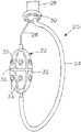
图1为一实施例的示意图,其包括一射频气囊融除装置,配以可调环引导丝系统控制的分段电极;Fig. 1 is a schematic diagram of an embodiment, which includes a radio frequency balloon ablation device, equipped with segmented electrodes controlled by an adjustable ring guide wire system;
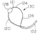
图2为描述一实施例的示意图,其包括一带有内外同轴气囊的低温气囊融除装置,所述内外同轴气囊沿一可调环引导丝移动;Figure 2 is a schematic diagram illustrating an embodiment, which includes a cryogenic balloon ablation device with inner and outer coaxial balloons moving along an adjustable ring guide wire;
图3为描述一气囊融除装置的部分示意图,所述气囊融除装置配有一控制柄,适用于本发明气囊融除导管装置的使用;Fig. 3 is a partial schematic diagram depicting a balloon ablation device equipped with a control handle suitable for the use of the balloon ablation catheter device of the present invention;
图4A-4E从不同角度展示所述融除气囊装置,以及可由所述可调引导丝配合一拉线生成的各种形状和环;4A-4E show the ablation balloon device from different angles, and various shapes and loops that can be generated by the adjustable guide wire and a pull wire;
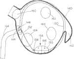
图5为一射频或低温气囊融除装置的示意图,通过一环引导丝安置于左心房以形成环形损伤;Fig. 5 is a schematic diagram of a radiofrequency or low temperature balloon ablation device, which is placed in the left atrium through a loop guide wire to form a circular injury;
图6为描述一射频或低温气囊融除装置的示意图,所述装置使用一固定于左心耳的固定引导丝;FIG. 6 is a schematic diagram describing a radiofrequency or cryogenic balloon ablation device using a fixed guide wire fixed to the left atrial appendage;
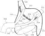
图7为展示一射频或低温融除气囊,在左上腔肺静脉中配以分段电极以及由引导丝导向的热敏电阻,以形成一肺静脉隔离损伤;Figure 7 shows a radiofrequency or cryogenic ablation balloon with segmented electrodes and a thermistor guided by a guide wire in the left superior vena cava to form a pulmonary vein isolation injury;
图8为一气囊导管结合一J环肺静脉记录及阻抗测量导管装置的示意图,能测量肺静脉闭合及损伤质量,成熟及电性隔离;8 is a schematic diagram of a balloon catheter combined with a J-ring pulmonary vein recording and impedance measurement catheter device, which can measure pulmonary vein closure and injury quality, maturity and electrical isolation;
图9描述了制造线性损伤的多电极,环类导管的示意图;Figure 9 depicts a schematic diagram of a multi-electrode, loop-like catheter for making a linear lesion;
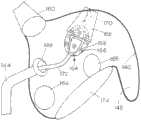
图10为类似于图9中的导管的示意图,显示肺静脉中固定支撑护套在右上腔肺静脉与左上腔肺静脉之间的线性损伤的布置;Figure 10 is a schematic diagram of the catheter similar to that in Figure 9, showing the placement of a linear lesion in the pulmonary veins to secure the support sheath between the right and left superior vena cava;
图11为类似于图10的示意图,显示左上腔肺静脉与左下腔肺静脉之间的线性损伤的布置;Figure 11 is a schematic diagram similar to Figure 10 showing the placement of a linear lesion between the left superior and left inferior vena cava;
图12为类似于图10的示意图,显示左下腔肺静脉与右下腔肺静脉之间的线性损伤的布置;Figure 12 is a schematic diagram similar to Figure 10 showing the placement of a linear lesion between the left and right inferior vena cava;
图13为类似于图10的示意图,显示右下腔肺静脉与右上腔肺静脉之间的线性损伤的布置;Figure 13 is a schematic diagram similar to Figure 10 showing the placement of a linear lesion between the right inferior and right superior vena cava;
图14为一多电极环类导管的替代实施例的示意图,所述导管包括一隔离伸杆;Figure 14 is a schematic diagram of an alternate embodiment of a multi-electrode loop-type catheter including a spacer extension rod;
图15阐释了图14中的多电极导管,所述导管可能用来在肺静脉之间制造线性损伤;Figure 15 illustrates the multi-electrode catheter of Figure 14, which may be used to create a linear lesion between the pulmonary veins;
图16为一融除控制系统的图解及部分流程图;Fig. 16 is a diagram and a partial flowchart of an ablation control system;
图17为另一射频气囊融除装置实施例的示意图,所述装置配有收缩状态下的气囊,且为清楚起见,部分气囊被移除;Figure 17 is a schematic illustration of another embodiment of a radiofrequency balloon ablation device with the balloon in a deflated state, with portions of the balloon removed for clarity;
图18A以及18B分别对比了图17中的带收缩状态下的气囊的融除装置和带膨胀状态下的气囊的融除装置;Figures 18A and 18B respectively compare the ablation device with the balloon in the contracted state and the ablation device with the balloon in the expanded state in Figure 17;
图19为一导管装置的碎片或部分视图,包括图17中的气囊融除装置;Figure 19 is a fragmentary or partial view of a catheter device including the balloon ablation device of Figure 17;
图20A与20B为图17中气囊横断面的示意图;20A and 20B are schematic views of the cross-section of the airbag in FIG. 17;
图21A与21B为一略有不同的射频气囊融除装置的示意图,所述装置电极的配置是倾斜的;21A and 21B are schematic diagrams of a slightly different radio frequency balloon ablation device, the configuration of the electrodes of the device is inclined;
图22A与22B分别是另一气囊融除装置处于收缩状态下和膨胀状态下的示意图。22A and 22B are schematic diagrams of another balloon ablation device in a contracted state and in an expanded state, respectively.
具体实施方式Detailed ways
以下具体实施方式属于包括本发明概念的多个实施例。所述实施例仅是本发明的较佳实施例,但这并不说明本发明仅限于这些实施例。The following detailed description pertains to a number of embodiments that encompass the inventive concept. The embodiments described are only preferred embodiments of the present invention, but this does not mean that the present invention is limited to these embodiments.
在将来值得注意的是,本发明正在谋划一种相对有效且微创的心房纤颤治疗方法,以通过使用导管的组织融除制造损伤取代传统迷宫术产生的手术损伤,避免了对根治外科手术的需要。本发明所述融除装置为组织接触提供了坚固且持续的融除界面。It is worth noting in the future that the present invention is contemplating a relatively effective and minimally invasive treatment of atrial fibrillation to replace the surgical injury produced by the traditional maze technique by creating the injury by tissue ablation using a catheter, avoiding the need for radical surgery needs. The ablation device of the present invention provides a strong and continuous ablation interface for tissue contact.
图1为一射频气囊融除装置实施例的示意图,以附图标记20表示。所述融除装置包括一处于充气膨胀状态的融除气囊22,所述气囊安装于一柔性拉通导管杆24,所述柔性拉通导管杆可为大约4英尺(122厘米)长的7F柔性拉通导管导向杆。所有融除控制以及数据测量导体或电线均被植入轴壁中,所述轴壁在引导丝26上移动。所述引导丝26的最远端部大约2厘米长,采用相对柔软、柔性的材料,要求比环的其余部分更柔软和柔性,环的其余部分相对坚硬。引导丝可附着于或拉穿于一可挠曲的透皮护套的远端部,所述护套的片段以28表示。一越膈缺口保护气囊以30表示,该气囊处于充气膨胀的状态,通常采用盐水防止其在手术过程中从护套28中缩回。使用一近端操作柄相对所述引导丝26移动可调杆24以调整所述导管的位置,见图3。FIG. 1 is a schematic diagram of an embodiment of a radiofrequency balloon ablation device, denoted by
所述气囊22进一步包括多个分段的传导涂料涂覆的射频电极32,其中每个电极均配有一处于中心的记录电极以感应电活动,以及一记录-热敏电阻相结合的元件34用于感应温度。电极是气囊表面高度传导的涂层,可已一种被大家熟知的方式,可选及独立地被激活及感应到。所述气囊本身可是任何尺寸,一个典型的实施例是大约25-30毫米长,完全膨胀时直径达到15毫米。所述气囊选用合适的、良性的、可涂层的高分子材料,维持稳定的膨胀尺寸,且包含用于组织融除而设的分开的传导分段、放置于每个融除电极中心的热敏电阻、以及记录电极。所述首选材料为聚对苯二甲酸乙二酯(PET),也可选用其他合适的材料。The
如上所述,所述射频气囊在电极分段32中涂覆有高传导性的化合物,如图1所示。一典型优选实施例中的气囊长约30毫米,直径约为15毫米。所述气囊含8个分段传导的涂覆电极分段32,由非传导带36隔开,大约1.5毫米宽。所述记录及热敏电阻结合元件的直径一般大约为2毫米,通过1毫米隔离外环35与所述传导分段32隔开。大致位于每个融除元件中心的所述记录电极及热敏电阻监控着融除前后的电活动及温度。所述射频融除气囊优选在低压条件下装满混合有低浓度对比液的盐水。所述盐水在气囊中循环,同时维持所述气囊内恒定气压以保持气囊本身的低温,进而保证更有效的融除。As mentioned above, the RF balloon is coated with a highly conductive compound in the
图2描述了一基于本发明的低温融除装置的实施例,所述装置使用一双气囊系统,其包括一低温气囊及用于热隔离的低压隔离气囊。所述双气囊结构包括一内低温气囊42以及一外隔离气囊44。环电极46及48分别位于所述气囊的远端部及近端部,以记录电活动及验证位置。植入热敏电阻及记录电极,以50表示,位于外囊上指定位置,且以一种众所周知的方式互相连接。所述气囊装置安装在一柔性导管杆52上,所述柔性导管杆在引导丝54上移动。与所述射频装置一样,所述气囊的位置可通过在所述引导丝上推拉所述气囊导管导杆而改变。所述记录电极激活心电图及损伤评估。配置系统可能类似于图1中所述射频气囊的系统。因此,以54表示的引导丝环具有相对柔软柔性的截面,可通过一挠曲护套56的端部附着于一拉杆(未有图示)。所述护套56包括一越膈保护气囊58。Figure 2 depicts an embodiment of a cryogenic ablation device according to the present invention using a dual bladder system comprising a cryogenic bladder and a low pressure isolation bladder for thermal isolation. The double airbag structure includes an inner low temperature airbag 42 and an outer isolation airbag 44 . Ring electrodes 46 and 48 are located at the distal and proximal portions of the balloon, respectively, to record electrical activity and verify position. Implanted thermistors and recording electrodes, indicated at 50, are positioned on the outer capsule at designated locations and interconnected in a well-known manner. The balloon device is mounted on a flexible catheter shaft 52 which travels over a guide wire 54 . As with the RF device, the position of the balloon can be changed by pushing and pulling the balloon catheter guide rod over the guide wire. The recording electrodes activate ECG and injury assessment. The configuration system may be similar to that of the RF airbag described in FIG. 1 . Thus, the guide wire loop indicated at 54 has a relatively soft and flexible cross-section and can be attached to a tie rod (not shown) by the end of a flex sheath 56 . The sheath 56 includes a transdiaphragmatic protective balloon 58 .
在两个气囊低温系统中,所述内囊接收并容纳一低温液体物质,可选液态一氧化二氮,其于零下88.5℃沸腾;所述外囊充满一隔离气体,可选二氧化碳或氮气,压力刚好高于左心房压力。如此一来,所述低温液化气体则与所述内心房血流隔离开来。在融除过程中,所述引导丝环的延伸促使所述气囊压向感兴趣的位置的组织,该压力将组织接触区域中的隔离气体转移,由此促使所述低温内囊与所述外囊紧密接触,而外囊在所述气囊以及所述组织之间产生最大热传递,以获得最大限度的局部组织冷却。In the two-bag cryogenic system, the inner bag receives and holds a cryogenic liquid substance, optionally liquid nitrous oxide, which boils at minus 88.5°C; the outer bag is filled with an isolated gas, optionally carbon dioxide or nitrogen, The pressure is just above the left atrial pressure. In this way, the cryogenic liquefied gas is isolated from the inner atrial blood flow. During ablation, extension of the guidewire loop causes the balloon to press against tissue at the location of interest, which pressure displaces insulating gas in the tissue contact region, thereby urging the cryogenic inner balloon to contact the outer balloon. The balloons are in intimate contact, while the outer balloon creates maximum heat transfer between the balloon and the tissue for maximum localized tissue cooling.
提供了一控制柄(图3)推动所述气囊杆在所述引导丝上前进,调整其在所述引导丝上的位置,如图4A-4B所示。A control handle (Fig. 3) is provided to push the airbag rod forward on the guide wire and adjust its position on the guide wire, as shown in Figs. 4A-4B.
图3为一气囊导管融除系统80实施例的示意图,该系统包括一含射频/冷冻机连接器82的扁平控制柄构件81,用于将液体物质施加到一气囊88。带一远端导管轴滑动或操作柄83的融除(射频/冷冻剂)气囊导管伸入一导护套84,如图所示。所述远端柄83为所述气囊融除导管90的远端部。所述导管可滑动地设在引导丝86上,两者通过所述导护套84被传送至心房,或另一心腔。所述融除气囊导管轴从引导丝相对坚硬的部分插入所述可挠曲护套。当所述气囊导管沿着所述引导丝移动时,所述引导丝相对柔软的部分从所述护套延伸出,且可被锁定以防止引导丝进一步向所述护套漂移或移动。为达到此目的,需提供一可移动锁定装置,以87表示。通过沿着并在所述引导丝截面86上移动所述导管远端柄83可改变所述气囊沿所述引导丝环的位置。引导丝固定锁以92表示。所述固定锁允许可变长度的引导丝固定点改变所述投射环的尺寸,并使所述融除气囊覆盖额外距离。由所述柄83控制的所述融除气囊导管在可调引导丝环94上的滑动范围如箭头85所示。可挠曲护套截面以98表示,柔性的引导丝环段以94表示。护套挠曲环以100表示。3 is a schematic diagram of an embodiment of a balloon catheter ablation system 80 including a flat handle member 81 including an RF/cryo connector 82 for applying liquid substance to a balloon 88 . The ablation (RF/cryogen) balloon catheter with a distal catheter shaft slide or handle 83 extends into a guide sheath 84 as shown. The distal handle 83 is the distal end of the balloon ablation catheter 90 . The catheter is slidably positioned over a guide wire 86, and the two are passed through the guide sheath 84 to the atrium, or another chamber of the heart. The ablation balloon catheter shaft is inserted into the flexible sheath from a relatively rigid portion of the guide wire. As the balloon catheter is moved along the guidewire, a relatively flexible portion of the guidewire extends from the sheath and may be locked to prevent further drift or movement of the guidewire toward the sheath. For this purpose, a movable locking device, indicated at 87, is provided. By moving the catheter distal handle 83 along and over the guide wire section 86 the position of the balloon along the guide wire loop can be changed. The guide wire fixation lock is indicated at 92 . The fixation lock allows variable length guidewire fixation points to vary the size of the projection ring and allow the ablation balloon to cover additional distance. The sliding range of the ablation balloon catheter on the adjustable guide wire ring 94 controlled by the handle 83 is shown by the arrow 85 . The flexible sheath section is indicated at 98 and the flexible guide wire loop segment is indicated at 94 . The sheath flex ring is indicated at 100 .
图4A-4E中的五幅图显示一融除导管轴120在一引导丝121上从一可挠曲护套122内部向前推动。所述引导丝124的远端部附着于一拉线或拉丝126,由一操作柄(未有图示)控制。气囊融除装置以128表示,在所述引导丝上前进。所述融除装置在图4A中呈瘪状。这种情况下,所述可挠曲导护套已穿透进入左心房或其他心腔。图4B中,所述气囊呈膨胀状态,且所述拉线126将所述引导丝124的端部拉向所述护套,由此形成一引导丝环。图4C中,所述引导丝的端部被拉回所述护套中,形成一环130。图4D及4E展示了将所述引导丝推进或缩回护套内可调整所述环130的尺寸。所述气囊128在所述引导丝的位置可通过所述融除气囊轴83(图3)在所述引导丝上前进或收缩而调整,如图4D到4E所示。Five of FIGS. 4A-4E show an
图5为左心房内由可调环引导丝引导的一融除气囊形成环形损伤的示意图。因此得到左心房壁以140表示,配以左心耳,以142表示。一越膈导护套144于左右心房间146穿过所述膈膜。所述护套包括一整体可充气膨胀的气囊148,其充满盐水以在手术过程中保护膈膜在越膈缺口处不被撕裂。所述气囊导管轴以150表示,以及所述带柔性分段的引导丝以152表示。所述分段的融除气囊可以是射频或低温融除装置,以154表示,在每个气囊表面分段配有热敏电阻及记录电电极,分别以155及156表示。进一步在所述气囊的每一端提供了环形电极,其中之一以158表示。该图还显示所述肺静脉出口的位置,包括所述右上腔肺静脉160,左上腔肺静脉162,右下腔肺静脉164以及左下腔肺静脉166。Fig. 5 is a schematic diagram of an ablation balloon guided by an adjustable loop guide wire in the left atrium to form a circular lesion. The resulting left atrial wall is denoted at 140 , together with the left atrial appendage, denoted at 142 . A
连同图5所示,所述分段融除气囊154由所述引导丝环紧固地抵靠在所述左心房140的壁上。通过插入更多所需引导丝调整所述引导丝环的尺寸,以及沿所述引导丝环增多引导丝以调整所述融除气囊154的位置,可以观察到所述左心房形成一完整的连续环形损伤。As shown together with FIG. 5 , the
图6所示与图5相近,表示了一替代系统用于固定所述分段涂覆融除气囊154,不采用所述环形系统,在本图的气囊154中,采用相对坚硬的引导丝170的固定柔软部分,将其植入所述左心耳142,之后该融除气囊可在所述引导丝170上追踪,以在所述左心房周围形成线性损伤。二尖瓣以174表示。Figure 6, similar to Figure 5, shows an alternative system for securing the segmented
图7为类似图6的一示意图,显示所述分段涂覆的融除气囊154被置于孔或房区域,刚好于所述左上腔肺静脉162之上,在那里融除气囊154被用于形成肺静脉的独立损伤。这样一来,每根所述肺静脉都可获得独立的肺静脉损伤。FIG. 7 is a schematic view similar to FIG. 6, showing the segmentally
图8是示意图,显示一射频或低温气囊180插入所述左上腔肺静脉196的孔中。所述气囊通过所述越膈护套182导入所述肺静脉以及J型4F环记录导管184。所述J环包括记录及刺激电极阵列186,所述气囊进一步提供有一远端环电极188以及一近端环电极190,用于测量融除过程中的阻抗(特别是使用低温气囊的条件下),以确定肺静脉闭合以及此后的损伤质量。心房壁以192表示,肺静脉分别以194,196,198以及200表示。为配合图8中的实施例使用,所述气囊导管180可采用图6和图7中显示的相同结构。若所述导管为一低温装置,在所述融除过程中形成冰球,且在低温融除过程中对所述冰球的记录及阻抗测量可以对所述冰球尺寸的损伤完成及融除功效进行确认。FIG. 8 is a schematic diagram showing the insertion of an RF or cryogenic balloon 180 into the hole of the left superior vena cava 196 . The balloon is introduced into the pulmonary vein and the J-type 4F ring recording catheter 184 through the transdiaphragmatic sheath 182 . The J-ring includes an array of recording and stimulating electrodes 186, and the balloon is further provided with a distal ring electrode 188 and a proximal ring electrode 190 for measuring impedance during ablation (especially when using a cryogenic balloon) , to determine pulmonary vein closure and the quality of the injury thereafter. The atrial wall is indicated at 192, and the pulmonary veins at 194, 196, 198 and 200, respectively. To cooperate with the embodiment shown in FIG. 8 , the balloon catheter 180 can adopt the same structure shown in FIGS. 6 and 7 . If the catheter is a cryogenic device, a puck is formed during the ablation process, and recording and impedance measurements of the puck during cryogenic ablation allow for confirmation of damage completion and ablation efficacy of the puck size .
值得注意的是,所述J型环肺静脉记录、刺激及阻抗测量导管结合所述气囊融除装置可通过低温气囊技术实现肺静脉隔离;尽管如此,成功的关键依赖于所述气囊与所述肺静脉组织的牢固接触以及所述肺静脉的完整闭合,这样在所述融除过程中不会有血液流入所述气囊周围的心房。将染料通过所述气囊引导丝中的一中央腔注入所述肺静脉可检验上述过程。若所述染料在静脉中凝集,可推断所述静脉已恰当闭合。若所述静脉未完全闭合,产生的损伤非完整的环形损伤,比如,若有缺口,或所述组织只是暂时丧失功能导致短时的隔离,将导致手术失败且需要额外干预。It is worth noting that the J-ring pulmonary vein recording, stimulation and impedance measurement catheter combined with the balloon ablation device can achieve pulmonary vein isolation by cryogenic balloon technology; however, the key to success depends on the relationship between the balloon and the pulmonary vein tissue. firm contact and complete closure of the pulmonary vein so that no blood flows into the atrium surrounding the balloon during the ablation procedure. Injection of a dye into the pulmonary vein through a central lumen in the balloon guidewire allows testing of this process. If the dye clumps in the vein, it can be concluded that the vein is properly occluded. If the vein is not completely closed, the resulting lesion is not a complete circular lesion, eg, if there is a gap, or the tissue is only temporarily incapacitated resulting in short-term isolation, the procedure will fail and require additional intervention.
值得注意的是,所述J-环记录/刺激导管的用途在于:(1)指导气囊融除导管将所述气囊相对于目标肺静脉孔纵向及靠中心放置;(2)固定所述导管于所述静脉中,所述环放置于静脉前庭中所述孔之上的位置;(3)射频或低温融除过程中,通过所述环电极186步测(pacing)膈神经,同时监测膈膜运动以确保膈神经不会被融除;(4)通过监测低温融除过程中的阻抗检测损伤成熟度;(5)射频及低温融除过程中测量静脉至心房或心房至静脉的传导。It is worth noting that the purpose of the J-ring recording/stimulation catheter is to: (1) guide the balloon ablation catheter to place the balloon longitudinally and centrally relative to the target pulmonary vein foramen; (2) fix the catheter on the In the vein, the ring is placed above the hole in the vestibule of the vein; (3) During radiofrequency or cryogenic ablation, the phrenic nerve is pacing through the ring electrode 186 while the diaphragm movement is monitored To ensure that the phrenic nerve will not be ablated; (4) to detect damage maturity by monitoring impedance during cryoablation; (5) to measure vein-to-atrium or atrium-to-vein conduction during radiofrequency and cryoablation.
低浓度射频能量也可被施加到所述远端气囊环电极188中,与位于所述气囊导管轴上近端的参考电极190(如图8所示)一起测量跨越所述气囊的导率。若所述气囊牢固地闭合所述肺静脉,阻抗上升且测量结构可确定肺静脉闭合。此外,当所述系统包括一低温气囊时,肺静脉闭合评估以及所述低温冰球的尺寸评估可通过测量近端气囊环电极190与远端气囊环电极188之间的阻抗变化来达到。鉴于冰是一种极端低劣的电导体,当所述冰球完全吞食所述肺静脉,观察到所述阻抗显著上升,由此提供了一种可靠的肺静脉闭合与低温损伤成熟度的指示器。Low concentration RF energy can also be applied to the distal balloon ring electrode 188 to measure conductance across the balloon along with a reference electrode 190 (shown in FIG. 8 ) located proximally on the balloon catheter shaft. If the balloon securely closes the pulmonary vein, the impedance rises and the measurement structure can confirm pulmonary vein closure. Additionally, when the system includes a cryogenic balloon, assessment of pulmonary vein closure and size of the cryopuck can be achieved by measuring the change in impedance between the proximal balloon ring electrode 190 and the distal balloon ring electrode 188 . Given that ice is an extremely poor electrical conductor, a significant rise in impedance was observed when the puck completely engulfed the pulmonary vein, thus providing a reliable indicator of pulmonary vein closure and maturity of hypothermic injury.
如图8所示的实施例中,配有多个间隔的环电极186及热敏电阻(未有显示)的J环首先放置于所述静脉中,以196表示。所述J环固定所述导管于所述静脉中,所述环位于所述静脉腔中,刚好位于所述孔之上,如图所示。所述气囊融除导管通过在所述J导管轴上前进导入其位置。通过传送低功率高频率的电流(可选用低于1瓦,550赫兹的电流)至所述J环上一个或多个电极186或至所述远端环电极(188)以及位于所述气囊近端的所述环电极190来测量基线阻抗。也可通过使用电极188及190测量所述气囊阻抗的方式测量上述阻抗。如上述,所述气囊膨胀以后,若所述静脉已坚固闭合,第二阻抗测量应显示阻抗上升,若只是部分闭合则不会监测出任何阻抗变化。额外的阻抗上升被所述低温气囊融除所记录,其显示吞食所述远端电极的冰球信息。In the embodiment shown in FIG. 8, a J-ring, indicated at 196, is first placed in the vein with a plurality of spaced ring electrodes 186 and a thermistor (not shown). The J-ring secures the catheter in the vein, the ring is located in the lumen of the vein just above the hole, as shown. The balloon ablation catheter is guided into its position by being advanced on the J-catheter shaft. By delivering a low-power high-frequency current (optionally less than 1 watt, 550 Hz current) to one or more electrodes 186 on the J-ring or to the distal ring electrode (188) and located near the balloon The ring electrode 190 at the end to measure the baseline impedance. This impedance can also be measured by measuring the balloon impedance using electrodes 188 and 190 . As mentioned above, after inflation of the balloon, if the vein is firmly closed, the second impedance measurement should show an increase in impedance, and if it is only partially closed, no change in impedance will be detected. An additional impedance rise was recorded by the cryoballoon ablation, which revealed information about the puck engulfing the distal electrode.
所述J导管优选为一预成形的3-4F导管,插入所述融除气囊的中心管中。所述导管的J形部分插入一静脉中,所述导管的环形部分围绕所述肺静脉的心房配有环形记录/刺激电极以及热敏电阻。所述气囊导管在作为引导丝的所述J导管上前进。所述气囊的定位能够闭合所述肺静脉,同时所述导管的环形部分围绕气囊接触肺静脉的远端部。将低功率射频施加于所述气囊轴或所述J导管的环部分上预选定的环电极,以测量气囊膨胀前后的阻抗以及融除过程中的阻抗,特别是在所述低温气囊实施例中。The J catheter is preferably a preformed 3-4F catheter inserted into the central tube of the ablation balloon. The J-shaped portion of the catheter is inserted into a vein and the annular portion of the catheter is fitted with annular recording/stimulating electrodes and thermistors around the atrium of the pulmonary vein. The balloon catheter is advanced over the J-catheter as a guide wire. The balloon is positioned to close the pulmonary vein while the annular portion of the catheter contacts the distal end of the pulmonary vein around the balloon. Applying low power radio frequency to preselected ring electrodes on the balloon shaft or the ring portion of the J-catheter to measure impedance before and after inflation of the balloon and during ablation, particularly in the cryogenic balloon embodiment .
使用时,应该明白的是,对于射频及低温气囊实施例,所述传送及组织接触步骤可以是一样的。所述高传导性元件及热敏电阻围绕所述射频及外低温气囊的外表面圆周分布。In use, it should be understood that the delivery and tissue contacting steps may be the same for both radiofrequency and cryogenic balloon embodiments. The high conductivity element and thermistor are distributed around the outer surface of the radio frequency and outer low temperature airbag.
图9示意图包括本发明的一替代实施例,其形式为多融除电极型导管系统,用于形成线性损伤尤其是在肺静脉之间的组织上形成线性损伤以实现组织的隔离,这被视为成功达到心房纤颤融除的重要方面。如图9所示,含有间隔的线绕融除电极阵列302的柔性多电极融除导管300从一具有两配件304及306的支撑护套装置伸出,从而构成以支撑及可扭转的融除导管支撑护套。所述导管支撑护套配件304及306从主越膈导护套308伸出。支撑护套的延伸件以310及312表示,用于锁定所述支撑护套至一可挠曲的越膈导护套的锁定装置以314表示。挠曲控制柄以316表示,融除导管连接器以318表示,通过连接线320向所述电极302提供电源。虽然其他尺寸也可用,所述柔性多电极融除导管300通常选用4F型,所示绕线电极302可选5毫米长中间带2毫米缺口。每个支撑及可扭转的导管导护套304及306被预定形,以被引入肺静脉。Figure 9 is a schematic diagram comprising an alternative embodiment of the present invention in the form of a multiple ablation electrode type catheter system for creating linear lesions especially on tissue between pulmonary veins to achieve tissue isolation, which is considered Important aspects of successful ablation of atrial fibrillation. As shown in FIG. 9 , a flexible multi-electrode ablation catheter 300 containing spaced wire-wound
导护套304及306在成对肺静脉中的布置如图10-13所示,其中左心房壁以330表示,肺静脉包括右上腔肺静脉332,左上腔肺静脉334,右下腔肺静脉336及左下腔肺静脉338。左心耳以340表示,二尖瓣以342表示(见图10)。The arrangement of
照此方式,图10阐明了一线性损伤如何在所述右上腔肺静脉332及所述左上腔肺静脉334之间形成。注意的是,稳定及支撑导护套304及306实现了穿透进入肺静脉的开孔和腔,并提供了对所述导管电极阵列的支持。热敏电阻344可置于所述融除/记录电极302之间。同样的方式,图11显示了所述左上腔肺静脉334及所述左下腔肺静脉338之间的融除。图12显示了所述左下腔肺静脉338及所述右下腔肺静脉336之间的融除。图13阐明了所述右上腔肺静脉332及所述右下腔肺静脉336之间的融除。In this way, FIG. 10 illustrates how a linear lesion is formed between the right
因此,所述柔性多电极融除导管300被置于一对更加坚硬的导护套304及306中,所述导护套再置于可挠曲的导护套308,即越膈装置中。使用时,一旦所述主护套进入目标心腔,所述融除导管300及所述两个支撑导护套304及306从所述主护套中移出并进入到所述心腔中。每个所述支撑导护套304及306被预定形,以被引入肺静脉。推和/或旋转其近端部进出所述可挠曲的主护套308,使所述支撑导护套304及306单独前进。通过在所述挠曲控制柄316上释放或束缚所述锁定装置314可锁定所述支撑护套在适当的位置上。一旦所述支撑护套被迫进入目标肺静脉,同时保持所述融除导管在所述组织之间拉紧,就确保了与目标组织与融除导管的良好接触。另一实施例如图14及15所示。该实施例实质上是图9-13所示的实施例的简化版本,其中多电极导管400配有绕线融除及测量电极402及中间热敏电阻404,它被直接插入所述可挠曲的主导护套406以在所述护套的端部形成环。以408表示的伸杆用来修正所述环的形状。柄及挠曲控制器以410表示,配有锁定装置412及多电极热敏电阻连接器,以414表示。伸杆控制器以416表示,带挡块的拉弦以418表示。膈膜保护气囊以420表示。图15中,左心房壁以422表示,左心耳以424表示。所述肺静脉孔以426,428,430及432表示,二尖瓣以434表示。在展开之前缩回在所述可挠曲的主导护套的孔中的融除导管400,可使用所述拉弦或拉线418将所述主要导护套406的尺寸最小化。注意的是,所述隔离延伸柔性杆408向所述导管环提供进一步的支撑及稳定,改善组织接触情况。通过偏转旋转中的主导护套、融除导管的扭力延伸及导管环的扩张、隔离杆408的扩张或收缩,可使导管移动及定位。Thus, the flexible multi-electrode ablation catheter 300 is placed within a pair of more
图16为根据本发明用于射频融除系统的监控系统的示意图。该系统包括一导管系统500,一气囊导管502安装于在引导丝506上行进的导管轴504上。护套以508表示。所述气囊导管包括多个热敏电阻及记录电极510以及射频融除电极512。所述导管进一步包括机械操作式控制器和液态膨胀及循环控制器,以514块表示。FIG. 16 is a schematic diagram of a monitoring system for a radiofrequency ablation system according to the present invention. The system includes a
射频能发生器系统包括输入输出数据处理,电记录图射频过滤器以520表示,连接于射频控制系统522。所述射频发生器连接至可视输出或屏幕显示装置,以524块表示,在526处连接记录系统。The radio frequency energy generator system includes input and output data processing, and the electrogram radio frequency filter is indicated by 520, which is connected to the radio
写入所述射频能发生器的程序用于控制任何多电极射频导管系统中的每个融除电极并调整其射频能,每个电极单独地连接并单独地被控制。控制所述能量的传送,以保证只有与目标组织紧密接触的电极可以获能量,并且所需的能量在精确的控制之下,以避免使血液或融除的组织过热。融除组织的过热可引起烧焦,甚至引发中风。因此,每个独立的能量源会根据感应到的温度及反映温度上升率的温度变化的一阶导数进行调整。实时局部电活动也在严密监控之下。这包括记录电图振幅、局部电图及阻抗变化时最大频率的变化。The RF energy generator is programmed to control and adjust the RF energy of each ablation electrode in any multi-electrode RF catheter system, each electrode being individually connected and individually controlled. The delivery of the energy is controlled to ensure that only electrodes in close contact with the target tissue are energized, and that the required energy is under precise control to avoid overheating the blood or the ablated tissue. Excessive heat from ablated tissue can cause charring and even stroke. Thus, each individual energy source is adjusted based on the sensed temperature and the first derivative of the temperature change reflecting the rate of temperature rise. Real-time local electrical activity is also closely monitored. This includes recording electrogram amplitude, local electrogram, and changes in maximum frequency as impedance changes.
一旦射频能开启,所述能量发生器系统根据一预编程序调整所述射频能,可如下:Once the RF energy is turned on, the energy generator system adjusts the RF energy according to a pre-programmed program, which may be as follows:
1.在可接受的参数内确定接触及组织活性后,1. After determining exposure and tissue activity within acceptable parameters,
a.局部电图>1mV,a. Local electrogram>1mV,
b.最大电图频率>8Hz,b. Maximum electrogram frequency > 8Hz,
c.阻抗<180ohms.c.Impedance<180ohms.
由低能设定开始,能量逐渐增高以控制在一预设水平的电极温度变化率,例如每秒5℃=dT/dt;Starting from a low energy setting, the energy is gradually increased to control the temperature change rate of the electrode at a preset level, for example, 5°C per second=dT/dt;
2.达到最大预设温度,例如65℃;2. Reach the maximum preset temperature, such as 65°C;
3.若阻抗上升超过一预设水平(例如150-180ohms),或若所述局部电图从基线水平下降50%或更多,和/或连和所述电图振幅考虑,若所述局部电图频率从所述基线值下降比如说30%,则中断能量输入。3. If the impedance rises above a predetermined level (eg, 150-180 ohms), or if the local electrogram falls by 50% or more from the baseline level, and/or taking into account the electrogram amplitude, if the local If the electrographic frequency drops by say 30% from said baseline value, the energy input is discontinued.
4.在使用过程中,若可取的话,第3点中的某些值可被重写(override)。4. During use, some values in point 3 can be overridden if desired.
5.当电图数据及阻抗测量指示融除成功时,降低能量到最小。5. When electrogram data and impedance measurements indicate successful ablation, reduce energy to minimum.
所述射频能发生器系统被设计用作接收关于所有必要参数的数据,所述数据来自所述融除电极及热敏电阻,包括局部电图振幅及变化百分比、最大电图频率温度、温度(dT/dt)阻抗变化率、输出能及应用时间。The radiofrequency energy generator system is designed to receive data on all necessary parameters from the ablation electrode and thermistor, including local electrogram amplitude and percent change, maximum electrogram frequency temperature, temperature ( dT/dt) Impedance change rate, output energy and application time.
在接收到的数据显示局部组织已成功融除,能源也被中断后,所述导管可为下一局部组织融除重新定位。After the received data shows that the local tissue has been successfully ablated and the energy source is interrupted, the catheter can be repositioned for the next local tissue ablation.
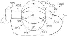
射频气囊融除导管装置的另一实施例大致以图17中600表示,配有处于完全收缩状态的气囊。所述装置包括一外管状构件、具有分段的导向导管602或导护套603。所述导向导管或导护套包括可充气膨胀的气囊部分604,位于分段之间。可充气膨胀的部分604配有传导性电极融除元件606,连接于轴分段602及603之间。所述电极元件首选为传导性带状形式,安装在可充气膨胀的内气囊装置607的外部并独立于该内气囊装置607。当所述装置的膨胀部分604处于如图20B所示的收缩或存储位置时,在图20A及20B中清晰可见的电极元件重叠,当所述气囊装置607如图20A膨胀时微微分开。如此,所述膨胀或气囊装置可用来控制已展开的融除装置元件所限定的直径。尽管上述图例描述了四个电极元件,任何合适的数量都可采用。所述元件都独立连接,包括融除装置、温度装置、以及电活动监控装置。Another embodiment of a radiofrequency balloon ablation catheter device is shown generally at 600 in FIG. 17 with the balloon in a fully deflated state. The device includes an outer tubular member, a
外导管轴包含额外的内同心中空管,包括中间管状件608以及最内部的管状件610。所述最内部的管状件连接至所述导管612的尖部,并包含一轴向可调整的引导丝614。如图17中所示。管状件610也提供一条路径供手术中注射的液体从所述导管柄传导且通过所述导管传送。略大的中间管状件608连接607中604部分的所述膨胀气囊装置的内部,且为膨胀液提供一条路径。所述外管或导管轴配件包括以616表示的电线,所述电线连接到所述融除元件以及以618表示的植入所述融除元件606的热敏电阻配件及记录电极。The outer catheter shaft contains additional inner concentric hollow tubes, including a middle
图18A及18B显示了所述中空融除装置600分别在所述膨胀或气囊装置处于收缩及膨胀状态的对比。如图20B所示,所述带状电极配件606在当所述气囊部分604处于收缩状态或存储位置时发生重叠,相反地,膨胀状态下的所述电极如图18B及20A所示被所述气囊的膨胀而稍微分开,小部分气囊材料607暴露出来。这使得暴露的融除电极表面最大化,但同时允许单独操作所述融除元件。这样的配置与单个气囊装置的安置一起可实现在肺静脉内对外围融除。所述带状融除元件应配置成在手术后,当所述气囊装置收缩或泄气时,所述融除元件再次恢复所述重叠配置,并且没有锐利边缘出现或暴露后对邻近组织产生不良作用。因所述带状电极606的端部固定于所述分段602与603之间,这些元件之间的的距离随所述气囊材料607的膨胀而缩小,所述系统的各元件独立地在所述引导丝614上移动。某些实施例中若需要更加坚硬的结构,所述轴可随所述气囊膨胀而挠曲。18A and 18B show a comparison of the
尤其如图18B及19所示,所述气囊融除导管装置进一步包括一中膈保护气囊630以及额外的导护套分段632。正如前述实施例,所述装置的目的在于穿透所述中膈组织,所述气囊630在手术过程中的膨胀防止所述导护套632穿过所述中膈组织被推回以及有可能引起膈膜损伤。一般来说,若涉及左心房融除,用该导护套从右心房到左心房穿透所述膈膜。如图18B及19所示,正如前述实施例,由引导丝614在心腔(例如左心房)中形成的引导丝环为所述融除气囊提供稳定的轨道,以便按顺序安放融除气囊,在心腔的外围形成线性损伤。所述气囊装置可按需要在手术过程中在所述引导丝上前进。例如前述实施例中的控制器,包括图3中所示柄控制器,可应用于任何实施例。As shown particularly in FIGS. 18B and 19 , the balloon ablation catheter device further includes a
替代的配置如图21A,21B以及22A,22B所描述。在图21A与21B中,射频气囊融除导管700与图17中的导管结构相似,包括带间隔开的导管轴配件702与703的导管轴,由膨胀部分704外的连接带状融除元件706连接。这些元件也配有植入的热敏电阻及记录电极,以718表示。其余结构和构件与图17中的相似,包括同轴管状件708及710,其功能与图17的实施例中的元件608及610相同。在本实施例中,所述带状电极配件706以螺旋模式排列在所述膨胀气囊融除部分704的外围。十字形模式如图21B中的704B所示。Alternative configurations are depicted in Figures 21A, 21B and 22A, 22B. In FIGS. 21A and 21B , a radiofrequency
在另一个与图22A与22B所描述的类似实施例中,射频气囊融除导管装置800包括带状电极806的模式,它同样也布置成格子或十字形的模式,其中分开的融除元件或电极彼此隔离。所述导管也包括分段802,803及804。引导丝管以808表示,引导丝以814表示。所述融除元件也配有植入的热敏电阻及电活动记录元件818。这样的模式也确保肺静脉孔中实现完整的环形融除。所述装置在图中以收缩或泄气的状态以及膨胀或鼓气的状态显示。In another embodiment similar to that described in FIGS. 22A and 22B , a radiofrequency balloon
尽管很多尺寸都可用,所述带状融除元件一般采用30毫米长3毫米宽的尺寸,且形状呈椭圆状。所述气囊融除导管在完全膨胀状态下的直径应该为20毫米,在收缩或存放状态时大约11F(3.6毫米)。所述气囊及电极可采用任何合适的且生物相容的普通材料。Although many sizes are available, the ribbon ablation elements typically measure 30 mm long by 3 mm wide and are oval in shape. The balloon ablation catheter should have a diameter of 20 mm in the fully inflated state and approximately 11F (3.6 mm) in the deflated or stowed state. The air bag and electrodes can be made of any suitable and biocompatible common materials.
由以上描述及图例显然可见,与本发明有关的独特性质在于所述实施例完成精确杰出的融除功能,尤其对在人类心脏中的心房纤颤的控制。尽管如此,所述装置及技术可用于心脏的任何部分。因此,可用于左右心腔以及心腔性心搏过速的心电图及融除。关于心房纤颤,根据本发明的导管系统已极大地改善了组织接触以及导管可追踪性,实现了更多可预测的损伤,同时将融除的组织量最少化。It is apparent from the above description and the illustrations that the unique property associated with the present invention is that the described embodiments perform precise and outstanding ablation functions, especially the control of atrial fibrillation in the human heart. Nonetheless, the devices and techniques described can be used with any part of the heart. Therefore, it can be used for electrocardiography and ablation of left and right chambers and chamber tachycardia. With respect to atrial fibrillation, the catheter system according to the present invention has greatly improved tissue contact and catheter trackability, enabling more predictable trauma while minimizing the amount of tissue ablated.
在此相当详细地描述了本发明,遵守了专利章程,为该领域中技能熟练的人员提供相关信息以助其使用新原理,以及按要求构建及使用如此专业的元件。但是必须认识到,本发明可以通过使用具体不同的设备及装置得以实施,并且各种对仪器本身及操作程序的修改都应属于本发明的范围之内。The invention is described herein in considerable detail, subject to the patent statute, to provide information to assist those skilled in the art in using the novel principles, and constructing and using such specialized components as required. However, it must be recognized that the present invention can be implemented by using specific different equipment and devices, and various modifications to the instrument itself and operating procedures should fall within the scope of the present invention.
Claims (83)
Applications Claiming Priority (5)
| Application Number | Priority Date | Filing Date | Title |
|---|---|---|---|
| US12/961,781US11246653B2 (en) | 2010-12-07 | 2010-12-07 | Catheter systems for cardiac arrhythmia ablation |
| US12/961,781 | 2010-12-07 | ||
| US13/106,309US8998893B2 (en) | 2010-12-07 | 2011-05-12 | Catheter systems for cardiac arrhythmia ablation |
| US13/106,309 | 2011-05-12 | ||
| PCT/US2011/063506WO2012078612A2 (en) | 2010-12-07 | 2011-12-06 | Catheter systems for cardiac arrhythmia ablation |
Publications (2)
| Publication Number | Publication Date |
|---|---|
| CN103347456Atrue CN103347456A (en) | 2013-10-09 |
| CN103347456B CN103347456B (en) | 2016-11-30 |
Family
ID=
Cited By (10)
| Publication number | Priority date | Publication date | Assignee | Title |
|---|---|---|---|---|
| CN104644161A (en)* | 2013-11-21 | 2015-05-27 | 韦伯斯特生物官能(以色列)有限公司 | Multi-electrode balloon catheter with peripheral and point electrodes |
| CN106794024A (en)* | 2014-07-22 | 2017-05-31 | 艾克西米斯外科有限责任公司 | Bulk tissue reduction and removal systems and methods |
| CN106852707A (en)* | 2015-12-08 | 2017-06-16 | 韦伯斯特生物官能(以色列)有限公司 | Ablation and sensing electrode |
| CN107205651A (en)* | 2014-12-05 | 2017-09-26 | 美敦力 | Temperature in use curve determines pulmonary vein and other angiemphraxises after cool brine injection |
| CN107456273A (en)* | 2016-06-02 | 2017-12-12 | 韦伯斯特生物官能(以色列)有限公司 | For the foley's tube for detecting occlusion and the related method based on impedance |
| CN107735038A (en)* | 2015-06-25 | 2018-02-23 | 柯惠有限合伙公司 | Tissue with adjustable cross sectional dimensions removes conduit |
| CN108201441A (en)* | 2016-12-20 | 2018-06-26 | 韦伯斯特生物官能(以色列)有限公司 | Two-piece type conduit shank |
| US10595922B2 (en) | 2014-12-05 | 2020-03-24 | Medtronic CyroCath LP | Contrast agent to assess quality of occlusion through impedance measurement |
| CN112220526A (en)* | 2020-12-10 | 2021-01-15 | 上海百心安生物技术有限公司 | Pulse balloon and using method |
| CN113813038A (en)* | 2021-09-10 | 2021-12-21 | 上海捍宇医疗科技股份有限公司 | Diameter-adjustable and guide-free pulsed electric field ablation catheter and equipment thereof |
Citations (6)
| Publication number | Priority date | Publication date | Assignee | Title |
|---|---|---|---|---|
| US5800482A (en)* | 1996-03-06 | 1998-09-01 | Cardiac Pathways Corporation | Apparatus and method for linear lesion ablation |
| US6475213B1 (en)* | 1996-01-19 | 2002-11-05 | Ep Technologies, Inc. | Method of ablating body tissue |
| US20030014049A1 (en)* | 1994-10-07 | 2003-01-16 | Koblish Josef V. | Loop structures for positioning a diagnostic or therapeutic element on the epicardium or other organ surface |
| US20040143249A1 (en)* | 2001-04-12 | 2004-07-22 | Scimed Life Systems, Inc., A Minnesota Corporation | Cryo balloon for atrial ablation |
| US20080312643A1 (en)* | 2004-12-22 | 2008-12-18 | Cryocath Technologies Inc. | Tissue ablation system including guidewire with sensing element |
| US20090299355A1 (en)* | 2008-05-27 | 2009-12-03 | Boston Scientific Scimed, Inc. | Electrical mapping and cryo ablating with a balloon catheter |
Patent Citations (6)
| Publication number | Priority date | Publication date | Assignee | Title |
|---|---|---|---|---|
| US20030014049A1 (en)* | 1994-10-07 | 2003-01-16 | Koblish Josef V. | Loop structures for positioning a diagnostic or therapeutic element on the epicardium or other organ surface |
| US6475213B1 (en)* | 1996-01-19 | 2002-11-05 | Ep Technologies, Inc. | Method of ablating body tissue |
| US5800482A (en)* | 1996-03-06 | 1998-09-01 | Cardiac Pathways Corporation | Apparatus and method for linear lesion ablation |
| US20040143249A1 (en)* | 2001-04-12 | 2004-07-22 | Scimed Life Systems, Inc., A Minnesota Corporation | Cryo balloon for atrial ablation |
| US20080312643A1 (en)* | 2004-12-22 | 2008-12-18 | Cryocath Technologies Inc. | Tissue ablation system including guidewire with sensing element |
| US20090299355A1 (en)* | 2008-05-27 | 2009-12-03 | Boston Scientific Scimed, Inc. | Electrical mapping and cryo ablating with a balloon catheter |
Cited By (20)
| Publication number | Priority date | Publication date | Assignee | Title |
|---|---|---|---|---|
| CN114376720B (en)* | 2013-11-21 | 2024-10-29 | 韦伯斯特生物官能(以色列)有限公司 | Multi-electrode balloon catheter with peripheral electrodes and point electrodes |
| US11617617B2 (en) | 2013-11-21 | 2023-04-04 | Biosense Webster (Israel) Ltd. | Multi-electrode balloon catheter with circumferential and point electrodes |
| CN104644161A (en)* | 2013-11-21 | 2015-05-27 | 韦伯斯特生物官能(以色列)有限公司 | Multi-electrode balloon catheter with peripheral and point electrodes |
| US10568686B2 (en) | 2013-11-21 | 2020-02-25 | Biosense Webster (Israel) Ltd. | Multi-electrode balloon catheter with circumferential and point electrodes |
| CN114376720A (en)* | 2013-11-21 | 2022-04-22 | 韦伯斯特生物官能(以色列)有限公司 | Multi-electrode balloon catheter with peripheral and spot electrodes |
| US10925665B2 (en) | 2014-07-22 | 2021-02-23 | Eximis Surgical, LLC | Large volume tissue reduction and removal system and method |
| CN106794024A (en)* | 2014-07-22 | 2017-05-31 | 艾克西米斯外科有限责任公司 | Bulk tissue reduction and removal systems and methods |
| CN106794024B (en)* | 2014-07-22 | 2019-11-12 | 艾克西米斯外科公司 | System and method for bulk tissue reduction and removal |
| CN107205651A (en)* | 2014-12-05 | 2017-09-26 | 美敦力 | Temperature in use curve determines pulmonary vein and other angiemphraxises after cool brine injection |
| US11471207B2 (en) | 2014-12-05 | 2022-10-18 | Medtronic Cryocath Lp | Assessing quality of occlusion |
| US10595922B2 (en) | 2014-12-05 | 2020-03-24 | Medtronic CyroCath LP | Contrast agent to assess quality of occlusion through impedance measurement |
| CN107205651B (en)* | 2014-12-05 | 2020-05-05 | 美敦力 | Use of temperature profiles to determine pulmonary vein and other vessel occlusions following cold saline injection |
| CN107735038A (en)* | 2015-06-25 | 2018-02-23 | 柯惠有限合伙公司 | Tissue with adjustable cross sectional dimensions removes conduit |
| CN107735038B (en)* | 2015-06-25 | 2020-07-17 | 柯惠有限合伙公司 | Tissue removal catheter with adjustable cross-sectional dimensions |
| CN106852707A (en)* | 2015-12-08 | 2017-06-16 | 韦伯斯特生物官能(以色列)有限公司 | Ablation and sensing electrode |
| CN107456273A (en)* | 2016-06-02 | 2017-12-12 | 韦伯斯特生物官能(以色列)有限公司 | For the foley's tube for detecting occlusion and the related method based on impedance |
| CN108201441A (en)* | 2016-12-20 | 2018-06-26 | 韦伯斯特生物官能(以色列)有限公司 | Two-piece type conduit shank |
| CN112220526A (en)* | 2020-12-10 | 2021-01-15 | 上海百心安生物技术有限公司 | Pulse balloon and using method |
| CN112220526B (en)* | 2020-12-10 | 2021-04-02 | 上海百心安生物技术股份有限公司 | Pulse balloon and using method |
| CN113813038A (en)* | 2021-09-10 | 2021-12-21 | 上海捍宇医疗科技股份有限公司 | Diameter-adjustable and guide-free pulsed electric field ablation catheter and equipment thereof |
Also Published As
| Publication number | Publication date |
|---|---|
| US20120143179A1 (en) | 2012-06-07 |
| WO2012078612A2 (en) | 2012-06-14 |
| JP2016013466A (en) | 2016-01-28 |
| CA2819056C (en) | 2015-02-03 |
| JP2018038861A (en) | 2018-03-15 |
| US8998893B2 (en) | 2015-04-07 |
| WO2012078612A3 (en) | 2012-09-13 |
| EP2648638B1 (en) | 2020-12-02 |
| JP6978286B2 (en) | 2021-12-08 |
| EP2648638A2 (en) | 2013-10-16 |
| CA2819056A1 (en) | 2012-06-14 |
| JP2014504909A (en) | 2014-02-27 |
| EP2648638A4 (en) | 2014-06-04 |
Similar Documents
| Publication | Publication Date | Title |
|---|---|---|
| US20220015827A1 (en) | Catheter Systems for Cardiac Arrhythmia Ablation | |
| JP6978286B2 (en) | Catheter system for ablating cardiac arrhythmias | |
| US12042218B2 (en) | Pulmonary vein isolation balloon catheter | |
| US20230414279A1 (en) | Ablation catheters and related systems and methods | |
| US9622806B2 (en) | Heated electrodes for continued visualization of pulmonary vein potentials | |
| EP3076888B1 (en) | Distal balloon impedance and temperature recording to monitor pulmonary vein ablation and occlusion | |
| US6640120B1 (en) | Probe assembly for mapping and ablating pulmonary vein tissue and method of using same | |
| US8123742B2 (en) | Catheter and method for ablation of atrial tissue | |
| US9636172B2 (en) | Compliant balloon with liquid injection | |
| US20110144637A1 (en) | Vein Occlusion Devices and Methods for Catheter-Based Ablation | |
| US9345529B2 (en) | Mapping wire with heating element to allow axial movement during cryoballoon ablation | |
| EP4072456A1 (en) | Tissue mapping and treatment | |
| US20210177509A1 (en) | Tissue mapping and treatment | |
| US20250009424A1 (en) | Electrode assembly including expandable isolation member | |
| US20070106290A1 (en) | Conformable electrode catheter and method of use | |
| US20250049490A1 (en) | Systems and methods for electrophysiological treatment | |
| CN103347456B (en) | Catheter Systems for Arrhythmia Ablation Therapy |
Legal Events
| Date | Code | Title | Description |
|---|---|---|---|
| C06 | Publication | ||
| PB01 | Publication | ||
| C10 | Entry into substantive examination | ||
| SE01 | Entry into force of request for substantive examination | ||
| C14 | Grant of patent or utility model | ||
| GR01 | Patent grant |