CN103346687A - Single-phase non-isolated photovoltaic grid-connected inverter topological structure and control method thereof - Google Patents
Single-phase non-isolated photovoltaic grid-connected inverter topological structure and control method thereofDownload PDFInfo
- Publication number
- CN103346687A CN103346687ACN2013102471476ACN201310247147ACN103346687ACN 103346687 ACN103346687 ACN 103346687ACN 2013102471476 ACN2013102471476 ACN 2013102471476ACN 201310247147 ACN201310247147 ACN 201310247147ACN 103346687 ACN103346687 ACN 103346687A
- Authority
- CN
- China
- Prior art keywords
- switching tube
- grid
- current
- filter capacitor
- filter
- Prior art date
- Legal status (The legal status is an assumption and is not a legal conclusion. Google has not performed a legal analysis and makes no representation as to the accuracy of the status listed.)
- Pending
Links
- 238000000034methodMethods0.000titleclaimsabstractdescription15
- 239000003990capacitorSubstances0.000claimsabstractdescription51
- 230000015572biosynthetic processEffects0.000claims2
- 238000010586diagramMethods0.000description12
- 230000007935neutral effectEffects0.000description4
- 238000002955isolationMethods0.000description3
- 230000007274generation of a signal involved in cell-cell signalingEffects0.000description2
- 238000001208nuclear magnetic resonance pulse sequenceMethods0.000description2
- 238000010248power generationMethods0.000description2
- XUIMIQQOPSSXEZ-UHFFFAOYSA-NSiliconChemical compound[Si]XUIMIQQOPSSXEZ-UHFFFAOYSA-N0.000description1
- 230000000295complement effectEffects0.000description1
- 230000000694effectsEffects0.000description1
- 230000008030eliminationEffects0.000description1
- 238000003379elimination reactionMethods0.000description1
- 238000005516engineering processMethods0.000description1
- 239000011521glassSubstances0.000description1
- 238000002347injectionMethods0.000description1
- 239000007924injectionSubstances0.000description1
- 239000002184metalSubstances0.000description1
- 230000005855radiationEffects0.000description1
- 239000004065semiconductorSubstances0.000description1
- 229910052710siliconInorganic materials0.000description1
- 239000010703siliconSubstances0.000description1
- 239000000243solutionSubstances0.000description1
Images


Classifications
- H—ELECTRICITY
- H02—GENERATION; CONVERSION OR DISTRIBUTION OF ELECTRIC POWER
- H02J—CIRCUIT ARRANGEMENTS OR SYSTEMS FOR SUPPLYING OR DISTRIBUTING ELECTRIC POWER; SYSTEMS FOR STORING ELECTRIC ENERGY
- H02J3/00—Circuit arrangements for AC mains or AC distribution networks
- H02J3/38—Arrangements for parallely feeding a single network by two or more generators, converters or transformers
- H02J3/381—Dispersed generators
- H—ELECTRICITY
- H02—GENERATION; CONVERSION OR DISTRIBUTION OF ELECTRIC POWER
- H02J—CIRCUIT ARRANGEMENTS OR SYSTEMS FOR SUPPLYING OR DISTRIBUTING ELECTRIC POWER; SYSTEMS FOR STORING ELECTRIC ENERGY
- H02J2300/00—Systems for supplying or distributing electric power characterised by decentralized, dispersed, or local generation
- H02J2300/20—The dispersed energy generation being of renewable origin
- H02J2300/22—The renewable source being solar energy
- H02J2300/24—The renewable source being solar energy of photovoltaic origin
- H—ELECTRICITY
- H02—GENERATION; CONVERSION OR DISTRIBUTION OF ELECTRIC POWER
- H02M—APPARATUS FOR CONVERSION BETWEEN AC AND AC, BETWEEN AC AND DC, OR BETWEEN DC AND DC, AND FOR USE WITH MAINS OR SIMILAR POWER SUPPLY SYSTEMS; CONVERSION OF DC OR AC INPUT POWER INTO SURGE OUTPUT POWER; CONTROL OR REGULATION THEREOF
- H02M7/00—Conversion of AC power input into DC power output; Conversion of DC power input into AC power output
- H02M7/42—Conversion of DC power input into AC power output without possibility of reversal
- H02M7/44—Conversion of DC power input into AC power output without possibility of reversal by static converters
- H02M7/48—Conversion of DC power input into AC power output without possibility of reversal by static converters using discharge tubes with control electrode or semiconductor devices with control electrode
- H02M7/483—Converters with outputs that each can have more than two voltages levels
- H02M7/487—Neutral point clamped inverters
- Y—GENERAL TAGGING OF NEW TECHNOLOGICAL DEVELOPMENTS; GENERAL TAGGING OF CROSS-SECTIONAL TECHNOLOGIES SPANNING OVER SEVERAL SECTIONS OF THE IPC; TECHNICAL SUBJECTS COVERED BY FORMER USPC CROSS-REFERENCE ART COLLECTIONS [XRACs] AND DIGESTS
- Y02—TECHNOLOGIES OR APPLICATIONS FOR MITIGATION OR ADAPTATION AGAINST CLIMATE CHANGE
- Y02E—REDUCTION OF GREENHOUSE GAS [GHG] EMISSIONS, RELATED TO ENERGY GENERATION, TRANSMISSION OR DISTRIBUTION
- Y02E10/00—Energy generation through renewable energy sources
- Y02E10/50—Photovoltaic [PV] energy
- Y02E10/56—Power conversion systems, e.g. maximum power point trackers
Landscapes
- Engineering & Computer Science (AREA)
- Power Engineering (AREA)
- Inverter Devices (AREA)
Abstract
Translated fromChineseDescription
Translated fromChinese技术领域technical field
本发明涉及一种单相非隔离光伏并网逆变器拓扑结构及其控制方法,属于光伏发电逆变领域。The invention relates to a single-phase non-isolated photovoltaic grid-connected inverter topology and a control method thereof, belonging to the field of photovoltaic power generation inverters.
背景技术Background technique
逆变器作为并网光伏发电系统的关键部件,高效率、低成本是其研究及设计的核心目标之一。常用的提高效率的方法是去除DC-DC升压变换器中的高频隔离变压器或输出端的低频隔离变压器。然后由于光伏板由玻璃、硅半导体和带有接地金属框的底板组成,所以在光伏板与地之间存在着电容,造成了一条漏电流通道,带来了传导和辐射干扰,不仅增加了进网电流谐波及损耗,且危及设备和人员安全。因此,研究新型无变压器拓扑结构,从而控制漏电流和直流电流的注入至关重要。As a key component of grid-connected photovoltaic power generation system, inverter is one of the core objectives of its research and design with high efficiency and low cost. A common way to improve efficiency is to remove the high-frequency isolation transformer in the DC-DC boost converter or the low-frequency isolation transformer at the output. However, since the photovoltaic panel is composed of glass, silicon semiconductor, and a base plate with a grounded metal frame, there is a capacitance between the photovoltaic panel and the ground, resulting in a leakage current channel, which brings conduction and radiation interference, which not only increases the network current harmonics and loss, and endanger the safety of equipment and personnel. Therefore, it is crucial to study novel transformerless topologies to control leakage current and DC current injection.
目前,基于全桥电路的单相非隔离光伏并网逆变器拓扑结构研究较多。如H5拓扑,它在一个典型的H桥的直流环节的正直流母线上添加了额外的第5个开关,从而实现在零电压状态下光伏模块和电网隔离。Heric拓扑,它在交流侧增加了一个采用两个背靠背IGBT器件的旁路桥臂。然而由于漏电流完全消除的条件是使续流阶段的续流回路电位钳位在光伏电池输入电压的一半,而不仅仅是使电池板与电网脱离,因此,虽满足漏电流相关指标,但可进一步完善。带直流旁路的全桥拓扑,在传统H桥基础上加入了两个额外的直流侧开关,以及两个额外的钳位二极管,从而将输出电压钳位至接地的直流母线中点,但在非零电压工作状态中,有4个开关管处于导通状态,导通损耗会增加。At present, there are many studies on the topology of single-phase non-isolated photovoltaic grid-connected inverters based on full-bridge circuits. Such as the H5 topology, which adds an additional fifth switch to the positive DC bus of a typical H-bridge DC link, so as to realize the isolation between the photovoltaic module and the grid in the zero-voltage state. Heric topology, which adds a bypass bridge arm with two back-to-back IGBT devices on the AC side. However, since the condition for complete elimination of leakage current is to clamp the potential of the freewheeling circuit in the freewheeling phase to half of the input voltage of the photovoltaic cell, not just to disconnect the battery panel from the grid, therefore, although the relevant indicators of leakage current are met, it can be further improvement. The full-bridge topology with DC bypass adds two additional DC-side switches and two additional clamping diodes to the traditional H-bridge to clamp the output voltage to the midpoint of the grounded DC bus, but at In the non-zero voltage working state, four switching tubes are in the conducting state, and the conduction loss will increase.
发明内容Contents of the invention
本发明要解决的技术问题是:针对背景技术中所提出的不足,提供一种低损耗、低漏电流的单相非隔离光伏并网逆变器拓扑结构及其控制方法,减少开关管的死区时间,从而得到无死区的逆变输出状态,提高输出波形质量。The technical problem to be solved by the present invention is to provide a low-loss, low-leakage current single-phase non-isolated photovoltaic grid-connected inverter topology and its control method to reduce the failure of switching tubes. Zone time, so as to obtain the inverter output state without dead zone, and improve the output waveform quality.
为了解决上述技术问题,本发明的技术方案是提供了一种单相非隔离光伏并网逆变器拓扑结构,其特征在于,包括光伏电池,光伏电池的两端并联有输入滤波电容,光伏电池的两端与全桥逆变环节连接,输入滤波电容与全桥逆变环节之间还连接有中点钳位开关,中点钳位开关和全桥逆变环节均通过LCL滤波器与电网连接。In order to solve the above technical problems, the technical solution of the present invention is to provide a single-phase non-isolated photovoltaic grid-connected inverter topology, which is characterized in that it includes photovoltaic cells, input filter capacitors are connected in parallel at both ends of the photovoltaic cells, photovoltaic cells Both ends of the inverter are connected to the full-bridge inverter link, and a mid-point clamp switch is also connected between the input filter capacitor and the full-bridge inverter link. Both the mid-point clamp switch and the full-bridge inverter link are connected to the power grid through the LCL filter .
优选地,所述的输入滤波电容包括相串联的第一滤波电容和第二滤波电容;Preferably, the input filter capacitor includes a first filter capacitor and a second filter capacitor connected in series;
所述的全桥逆变环节包括第一开关管、第二开关管、第三开关管、第四开关管,第一开关管和第三开关管的漏极与光伏电池的正极连接,第二开关管和第四开关管的源极与光伏电池的负极连接,第一开关管的源极与第二开关管的漏极相连,第三开关管的源极与第四开关管的漏极相连;The full-bridge inverter link includes a first switch tube, a second switch tube, a third switch tube, and a fourth switch tube, the drains of the first switch tube and the third switch tube are connected to the positive pole of the photovoltaic cell, and the second switch tube is connected to the positive pole of the photovoltaic cell. The sources of the switching tube and the fourth switching tube are connected to the negative pole of the photovoltaic cell, the source of the first switching tube is connected to the drain of the second switching tube, and the source of the third switching tube is connected to the drain of the fourth switching tube ;
所述的中点钳位开关包括第五开关管和第六开关管,第五开关管和第六开关管的集电极相连接后与第一滤波电容和第二滤波电容的中点相连,第五开关管的发射极与第一开关管的漏极相连,第六开关管的发射极与第三开关管的漏极相连;The midpoint clamping switch includes a fifth switch tube and a sixth switch tube, the collectors of the fifth switch tube and the sixth switch tube are connected to the midpoint of the first filter capacitor and the second filter capacitor, and the fifth switch tube and the sixth switch tube are connected to the midpoint of the first filter capacitor and the second filter capacitor. The emitter of the fifth switching tube is connected to the drain of the first switching tube, and the emitter of the sixth switching tube is connected to the drain of the third switching tube;
所述的LCL滤波器包括第一滤波电感、并网滤波电容以及第二滤波电感,第一滤波电感的一端连接至第一开关管的漏极,第一滤波电感的另一端分别连接并网滤波电容的一端、第二滤波电感的一端,第二滤波电感的另一端连接电网的火线端,并网滤波电容的另一端连接至电网的零线端、第三开关管的漏极。The LCL filter includes a first filter inductor, a grid-connected filter capacitor and a second filter inductor, one end of the first filter inductor is connected to the drain of the first switching tube, and the other end of the first filter inductor is respectively connected to the grid-connected filter One end of the capacitor, one end of the second filter inductor, the other end of the second filter inductor is connected to the live wire end of the grid, and the other end of the grid-connected filter capacitor is connected to the neutral wire end of the grid and the drain of the third switch tube.
一种单相非隔离光伏并网逆变器拓扑结构的控制方法,其特征在于,包括以下步骤;A method for controlling the topology of a single-phase non-isolated photovoltaic grid-connected inverter, characterized in that it includes the following steps;
步骤1:对电路拓扑中的全桥逆变环节作单极性倍频SPWM调制,获得第一开关管、第二开关管、第三开关管、第四开关管的初始调制信号;Step 1: Perform unipolar frequency multiplication SPWM modulation on the full-bridge inverter link in the circuit topology to obtain the initial modulation signals of the first switching tube, the second switching tube, the third switching tube, and the fourth switching tube;
步骤2:根据并网电流的方向对各初始调制信号进行优化,当并网电流为正时,强制关闭第二开关管、第三开关管,并网电流为负时,强制关闭第一开关管、第四开关管;Step 2: Optimize each initial modulation signal according to the direction of the grid-connected current. When the grid-connected current is positive, the second switching tube and the third switching tube are forcibly turned off. When the grid-connected current is negative, the first switching tube is forcibly turned off. , the fourth switching tube;
步骤3:在输出电流换向时,加入一个死区时间,最终得到全桥逆变环节中第一开关管、第二开关管、第三开关管和第四开关管的调制信号;Step 3: When the output current commutates, a dead time is added to finally obtain the modulation signals of the first switching tube, the second switching tube, the third switching tube and the fourth switching tube in the full-bridge inverter link;
步骤4:电路拓扑中的中点钳位开关以调制波频率工作在工频状态,并网电流为正时,第五开关管打开,并网电流为负时,第六开关管打开。Step 4: The neutral point clamp switch in the circuit topology works at the power frequency state with the modulation wave frequency. When the grid-connected current is positive, the fifth switch is turned on, and when the grid-connected current is negative, the sixth switch is turned on.
优选地,包括以下4种工作状态:Preferably, the following 4 working states are included:
(1)输出正向电流的工作状态:第一开关管、第四开关管导通,第五开关管打开,其余开关管关断,进网电流经第一开关管、第一滤波电感、第二滤波电感、电网、第四开关管构成回路向电网供入正向电流;(1) The working state of outputting forward current: the first switching tube and the fourth switching tube are turned on, the fifth switching tube is turned on, and the rest of the switching tubes are turned off, and the incoming current passes through the first switching tube, the first filter inductor, the The second filter inductor, the grid, and the fourth switch tube form a loop to supply forward current to the grid;
(2)续流状态1:第五开关管导通,第一开关管与第四开关管同时关断或其中一个关断,其余开关管关断,电流经第五开关管、第一滤波电感、第二滤波电感、电网和第六开关管的二极管构成续流回路维持并网电流,并由第一滤波电容、第二滤波电容的中点将续流回路电位钳位在光伏电池电压的一半;(2) Freewheeling state 1: the fifth switching tube is turned on, the first switching tube and the fourth switching tube are turned off at the same time or one of them is turned off, the other switching tubes are turned off, and the current passes through the fifth switching tube and the first filter inductor , the second filter inductance, the power grid and the diode of the sixth switch tube form a freewheeling circuit to maintain the grid-connected current, and the midpoint of the first filter capacitor and the second filter capacitor clamps the potential of the freewheeling circuit to half of the photovoltaic cell voltage ;
(3)输出反向电流的工作状态:第二开关管、第三开关管导通,第五开关管打开,其余开关管关断,进网电流经第三开关管、电网、第二滤波电感、第一滤波电感、第二开关管构成回路向电网供入反向电流;(3) The working state of the output reverse current: the second switch tube and the third switch tube are turned on, the fifth switch tube is turned on, and the other switch tubes are turned off, and the incoming current passes through the third switch tube, the grid, and the second filter inductor , The first filter inductor and the second switch tube form a loop to supply reverse current to the power grid;
(4)续流状态2:第六开关管导通,第二开关管与第三开关管同时关断或其中一个关断,其余开关管关断,电流经第六开关管、电网、第二滤波电感、第一滤波电感和第五开关管的二极管构成续流回路维持并网电流,并由第一滤波电容、第二滤波电容的中点将续流回路电位钳位在光伏电池电压的一半。(4) Freewheeling state 2: the sixth switching tube is turned on, the second switching tube and the third switching tube are turned off at the same time or one of them is turned off, and the other switching tubes are turned off, and the current passes through the sixth switching tube, the power grid, the second switching tube The filter inductance, the first filter inductance and the diode of the fifth switching tube form a freewheeling circuit to maintain the grid-connected current, and the midpoint of the first filter capacitor and the second filter capacitor clamps the potential of the freewheeling circuit to half of the voltage of the photovoltaic cell .
本发明为一种单相非隔离光伏并网逆变器拓扑结构,包括相连接的输入滤波电容、全桥逆变环节、中点钳位开关以及LCL滤波器支路。在传统H桥电路的基础上增加了两个额外的开关管,即中点钳位开关,用于在续流状态下将输出电压钳位至直流侧电位的中点,即在续流阶段实现了将续流回路电位钳制为光伏电池电压的一半,从而消除了非隔离并网逆变器的漏电流。另外通过所提出的控制方法消除了高频调制过程中因增加死区时间而产生的输出电压畸变。从而提高了光伏逆变系统的效率、降低了漏电流、降低了输出电压波形失真度,获得良好的输出电压波形,提高输出波形质量,并增加了系统的安全性,适合于非隔离型光伏并网逆变系统。The invention is a topology structure of a single-phase non-isolated photovoltaic grid-connected inverter, which includes a connected input filter capacitor, a full-bridge inverter link, a neutral point clamp switch and an LCL filter branch. On the basis of the traditional H-bridge circuit, two additional switch tubes are added, that is, the midpoint clamping switch, which is used to clamp the output voltage to the midpoint of the DC side potential in the freewheeling state, that is, it is realized in the freewheeling stage In order to clamp the freewheeling circuit potential to half of the photovoltaic cell voltage, the leakage current of the non-isolated grid-connected inverter is eliminated. In addition, the proposed control method eliminates the output voltage distortion caused by increasing the dead time in the high-frequency modulation process. Thereby improving the efficiency of the photovoltaic inverter system, reducing the leakage current, reducing the distortion of the output voltage waveform, obtaining a good output voltage waveform, improving the quality of the output waveform, and increasing the security of the system. It is suitable for non-isolated photovoltaic and Grid inverter system.
附图说明Description of drawings
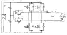
图1为本发明的电路拓扑结构连接示意图;Fig. 1 is a circuit topology connection schematic diagram of the present invention;
图2为光伏逆变全桥拓扑带死区单极性倍频SPWM调制波形图;Figure 2 is a photovoltaic inverter full-bridge topology with dead zone unipolar frequency multiplier SPWM modulation waveform diagram;
图3为本发明的电路拓扑中各开关管开关状态的控制信号产生电路框图;Fig. 3 is the control signal generation circuit block diagram of each switching tube switching state in the circuit topology of the present invention;
图4为本发明的电路拓扑中各开关管开关状态及逆变输出电压波形图;Fig. 4 is each switching tube switching state and inverter output voltage waveform diagram in the circuit topology of the present invention;
图5为本发明的电路拓扑输出正向电流的工作状态示意图;Fig. 5 is the working state schematic diagram of circuit topology output forward current of the present invention;
图6为本发明的电路拓扑续流状态1的示意图;Fig. 6 is the schematic diagram of circuit
图7为本发明的电路拓扑输出反向电流的工作状态示意图;7 is a schematic diagram of the working state of the circuit topology output reverse current of the present invention;
图8为本发明的电路拓扑续流状态2的示意图。FIG. 8 is a schematic diagram of the freewheeling state 2 of the circuit topology of the present invention.
其中,1-输入滤波电容,C1-第一滤波电容,C2-第二滤波电容,2-全桥逆变环节,S1-第一开关管,S2-第二开关管,S3-第三开关管,S4-第四开关管,3-中点钳位开关,S5-第五开关管,S6-第六开关管,4-LCL滤波器,L1-第一滤波电感,L2-第二滤波电感,C-并网滤波电容,Vg-电网,PV-光伏电池。Among them, 1-input filter capacitor, C1-first filter capacitor, C2-second filter capacitor, 2-full bridge inverter link, S1-first switch tube, S2-second switch tube, S3-third switch tube , S4-fourth switching tube, 3-midpoint clamp switch, S5-fifth switching tube, S6-sixth switching tube, 4-LCL filter, L1-first filter inductor, L2-second filter inductor, C-grid-connected filter capacitor, Vg-grid, PV-photovoltaic battery.
具体实施方式Detailed ways
为使本发明更明显易懂,兹以优选实施例,并配合附图作详细说明如下。In order to make the present invention more comprehensible, preferred embodiments are described in detail below with accompanying drawings.
一种单相非隔离光伏并网逆变器拓扑结构,如图1所示,其包括光伏电池PV,光伏电池PV的两端并联有输入滤波电容1,光伏电池PV的两端与全桥逆变环节2连接,输入滤波电容1与全桥逆变环节2之间还连接有中点钳位开关3,中点钳位开关3和全桥逆变环节2均通过LCL滤波器4与电网Vg连接。A single-phase non-isolated photovoltaic grid-connected inverter topology, as shown in Figure 1, which includes a photovoltaic cell PV, the two ends of the photovoltaic cell PV are connected in parallel with an
输入滤波电容1包括相串联的第一滤波电容C1和第二滤波电容C2;全桥逆变环节2包括第一开关管S1、第二开关管S2、第三开关管S3、第四开关管S4,第一开关管S1和第三开关管S3的漏极与光伏电池PV的正极连接,第二开关管S2和第四开关管S4的源极与光伏电池PV的负极连接,第一开关管S1的源极与第二开关管S2的漏极相连,第三开关管S3的源极与第四开关管S4的漏极相连;中点钳位开关3包括第五开关管S5和第六开关管S6,第五开关管S5和第六开关管S6的集电极相连接后与第一滤波电容C1和第二滤波电容C2的中点相连,第五开关管S5的发射极与第一开关管S1的漏极相连,第六开关管S6的发射极与第三开关管S3的漏极相连;LCL滤波器4包括第一滤波电感L1、并网滤波电容C以及第二滤波电感L2,第一滤波电感L1的一端连接至第一开关管S1的漏极,第一滤波电感L1的另一端分别连接并网滤波电容C的一端、第二滤波电感L2的一端,第二滤波电感L2的另一端连接电网Vg的火线端,并网滤波电容C的另一端连接至电网Vg的零线端、第三开关管S3的漏极。The
一种单相非隔离光伏并网逆变器拓扑结构的控制方法,包括以下步骤:A method for controlling the topology of a single-phase non-isolated photovoltaic grid-connected inverter, comprising the following steps:
步骤1:对电路拓扑中的全桥逆变环节2作单极性倍频SPWM调制,获得第一开关管S1、第二开关管S2、第三开关管S3、第四开关管S4的初始调制信号;Step 1: Perform unipolar frequency multiplication SPWM modulation on the full-bridge inverter link 2 in the circuit topology to obtain the initial modulation of the first switching tube S1, the second switching tube S2, the third switching tube S3, and the fourth switching tube S4 Signal;
步骤2:根据并网电流的方向对各初始调制信号进行优化,当并网电流为正时,强制关闭第二开关管S2、第三开关管S3,并网电流为负时,强制关闭第一开关管S1、第四开关管S4;Step 2: Optimize each initial modulation signal according to the direction of the grid-connected current. When the grid-connected current is positive, the second switching tube S2 and the third switching tube S3 are forcibly turned off; when the grid-connecting current is negative, the first switching tube S3 is forcibly turned off. Switch tube S1, fourth switch tube S4;
步骤3:在输出电流换向时,加入一个死区时间Δt,最终得到全桥逆变环节2中第一开关管S1、第二开关管S2、第三开关管S3和第四开关管S4的调制信号;Step 3: When the output current commutates, add a dead time Δt, and finally obtain the first switching tube S1, the second switching tube S2, the third switching tube S3 and the fourth switching tube S4 in the full-bridge inverter link 2 Modulated signal;
步骤4:电路拓扑中的中点钳位开关3以调制波频率工作在工频状态,并网电流为正时,第五开关管S5打开,并网电流为负时,第六开关管S6打开。Step 4: The midpoint clamp switch 3 in the circuit topology works at the power frequency state at the frequency of the modulating wave. When the grid-connected current is positive, the fifth switch tube S5 is turned on, and when the grid-connected current is negative, the sixth switch tube S6 is turned on. .
如图2所示,为光伏逆变全桥拓扑带死区单极性倍频SPWM调制波形图。倍频式SPWM技术是用一个正弦调制波与两个在相位上互补的三角形载波信号分别进行SPWM调制,输出电压相当于两个SPWM波形的代数相加,其消除和抑制谐波的效果相当于一个2倍载波频率的常规SPWM。为了防止同一桥臂上的两个开关管同时导通与直流侧发生短路,因此,在开关管导通前加入死区时间,从而导致输出电压的基波分量与理想的调制信号存在较大的偏差。As shown in Figure 2, it is the waveform diagram of the photovoltaic inverter full-bridge topology with dead zone unipolar frequency multiplication SPWM modulation. Multiplier SPWM technology uses a sinusoidal modulation wave and two complementary triangular carrier signals in phase to carry out SPWM modulation respectively. The output voltage is equivalent to the algebraic addition of two SPWM waveforms, and its effect of eliminating and suppressing harmonics is equivalent to A conventional SPWM at 2 times the carrier frequency. In order to prevent the two switching tubes on the same bridge arm from being turned on at the same time and short-circuiting the DC side, a dead time is added before the switching tubes are turned on, resulting in a large difference between the fundamental component of the output voltage and the ideal modulation signal. deviation.
如图3、图4所示,分别为本发明的电路拓扑中各开关管开关状态的控制信号产生电路框图、本发明的电路拓扑中各开关管开关状态及逆变输出电压波形图。正弦波发生器产生工频状态的调制信号uS,它分别与三角波发生器产生的高频调制信号uc1,和经过反相器后产生的调制信号uc2进行比较。As shown in Fig. 3 and Fig. 4, they are respectively a block diagram of the control signal generation circuit of each switching tube switching state in the circuit topology of the present invention, and a waveform diagram of each switching tube switching state and inverter output voltage in the circuit topology of the present invention. The sine wave generator generates the modulation signal uS in the power frequency state, which is compared with the high frequency modulation signal uc1 generated by the triangular wave generator and the modulation signal uc2 generated by the inverter.
调制信号uS和高频调制信号uc1的交点形成两列无死区的脉冲序列,作为一桥臂上的第一开关管S1、第二开关管S2的初始驱动信号。当并网电流为正时,将第二开关管S2强制关断,同时判断是否存在过零信号,若此时电流换向,过零状态为1,则通过死区控制让第一开关管S1延迟一个Δt时间后再打开,否则第一开关管S1按初始序列正常开关,图4中G1即为第一开关管S1的开关状态。当并网电流为负时,将第一开关管S1强制关断,同时判断是否存在过零信号,若此时电流换向,过零状态为1,则通过死区控制让第二开关管S2延迟一个Δt时间后再打开,否则第二开关管S2按初始序列正常开关,图4中G2即为第二开关管S2的开关状态。The intersection of the modulation signal uS and the high-frequency modulation signal uc1 forms two pulse sequences without dead zone, which are used as initial drive signals for the first switching tube S1 and the second switching tube S2 on a bridge arm. When the grid-connected current is positive, the second switching tube S2 is forcibly turned off, and at the same time, it is judged whether there is a zero-crossing signal. Turn on after a delay of Δt time, otherwise the first switching tube S1 switches normally according to the initial sequence, and G1 in FIG. 4 is the switching state of the first switching tube S1. When the grid-connected current is negative, the first switching tube S1 is forcibly turned off, and at the same time, it is judged whether there is a zero-crossing signal. If the current reverses at this time and the zero-crossing state is 1, the second switching tube S2 will Turn on after a delay of Δt, otherwise the second switching tube S2 switches normally according to the initial sequence, and G2 in FIG. 4 is the switching state of the second switching tube S2.
调制信号uS和调制信号uc2的交点同样形成两列无死区的脉冲序列,作为另一桥臂上的第三开关管S3、第四开关管S4的初始驱动信号。当并网电流为正时,将第三开关管S3强制关断,同时判断是否存在过零信号,若此时电流换向,过零状态为1,则通过死区控制让第四开关管S4延迟一个Δt时间后再打开,否则第四开关管S4按初始序列正常开关,图4中G4即为第四开关管S4的开关状态。当并网电流为负时,将第四开关管S4强制关断,同时判断是否存在过零信号,若此时电流换向,过零状态为1,则通过死区控制让第三开关管S3延迟一个Δt时间后再打开,否则第三开关管S3按初始序列正常开关,图4中G3即为第三开关管S3的开关状态。The intersection of the modulation signal uS and the modulation signal uc2 also forms two pulse sequences without dead zone, which are used as initial driving signals for the third switching tube S3 and the fourth switching tube S4 on the other bridge arm. When the grid-connected current is positive, the third switching tube S3 is forcibly turned off, and at the same time, it is judged whether there is a zero-crossing signal. If the current reverses at this time and the zero-crossing state is 1, the fourth switching tube S4 will Turn on after a delay of Δt, otherwise the fourth switching tube S4 switches normally according to the initial sequence, and G4 in FIG. 4 is the switching state of the fourth switching tube S4. When the grid-connected current is negative, the fourth switching tube S4 is forcibly turned off, and at the same time judge whether there is a zero-crossing signal. If the current reverses at this time and the zero-crossing state is 1, the third switching tube S3 is controlled by dead zone Turn on after a delay of Δt, otherwise the third switching tube S3 switches normally according to the initial sequence, and G3 in FIG. 4 is the switching state of the third switching tube S3.
中点钳位开关3的第五开关管S5、第六开关管S6的状态由调制信号uS的状态决定,当uS>0时,第五开关管S5导通,第六开关管S6关断,图4中G5即为第五开关管S5的开关状态;当uS<0时,第六开关管S6导通,第五开关管S5关断,图4中G6即为第六开关管S5的开关状态;The state of the fifth switch tube S5 and the sixth switch tube S6 of the midpoint clamp switch 3 is determined by the state of the modulation signal uS , when uS > 0, the fifth switch tube S5 is turned on, and the sixth switch tube S6 is turned off off, G5 in Figure 4 is the switching state of the fifth switching tube S5; when uS <0, the sixth switching tube S6 is turned on, and the fifth switching tube S5 is off, G6 in Figure 4 is the sixth switching tube Switch state of S5;
根据开关管S1~S6的开关状态,则输出电压uab的正半周由G1和G4的与逻辑决定,即由开关管S1、S4的状态决定,由于S1和S4不可能同时在过零点打开,其增加的死区时间不重叠,因此消除了输出正电压过程因死区产生的畸变。而输出电压uab的负半周由G2和G3的与逻辑决定,即由第二开关管S2、第三开关管S3的状态决定,同样,第一开关管S1和第四开关管S4不可能同时在过零点打开,其增加的死区时间亦不重叠,因此消除了输出为负电压时因死区产生的畸变。从而得到了全程无死区的输出电压波形。According to the switching states of the switching tubes S1~S6, the positive half cycle of the output voltage uab is determined by the AND logic of G1 and G4, that is, it is determined by the states of the switching tubes S1 and S4. Its increased dead time does not overlap, thus eliminating the distortion of the output positive voltage process due to the dead time. The negative half cycle of the output voltage uab is determined by the AND logic of G2 and G3, that is, it is determined by the states of the second switching tube S2 and the third switching tube S3. Similarly, the first switching tube S1 and the fourth switching tube S4 cannot be simultaneously Turning on at zero crossings also does not overlap the added dead time, thus eliminating distortion due to dead time when the output is negative. Thus, the output voltage waveform without dead zone in the whole process is obtained.
根据图4所得的开关管控制时序图,电路的整体工作过程分析如下:开关管S1~S4根据输出电流方向分别以载波频率工作在高频状态,钳位支路的第五开关管S5、第六开关管S6以调制波频率工作在工频状态,续流阶段,进网电流通过第五开关管S5、第六开关管S6构成续流回路,实现光伏电池输出端与电网脱离,并将续流回路电位钳制为光伏电池电压的一半。具体工作过程为:According to the switching tube control timing diagram obtained in Figure 4, the overall working process of the circuit is analyzed as follows: the switching tubes S1-S4 respectively work in a high-frequency state at the carrier frequency according to the direction of the output current, the fifth switching tube S5 and the fifth switching tube S5 of the clamping branch The six switch tubes S6 work at the power frequency state with the frequency of the modulated wave. During the freewheeling stage, the grid-incoming current passes through the fifth switch tube S5 and the sixth switch tube S6 to form a freewheel circuit, realizing the disconnection of the output terminal of the photovoltaic cell from the power grid, and continuing The current loop potential is clamped to half the photovoltaic cell voltage. The specific working process is:
如图5所示,输出正向电流的工作状态:第一开关管S1、第四开关管S4导通,第五开关管S5打开,其余开关管关断,进网电流经第一开关管S1、第一滤波电感L1、第二滤波电感L2、电网Vg、第四开关管S4构成回路向电网供入正向电流。As shown in Figure 5, the working state of outputting forward current: the first switching tube S1 and the fourth switching tube S4 are turned on, the fifth switching tube S5 is turned on, the other switching tubes are turned off, and the incoming current passes through the first switching tube S1 , the first filter inductor L1, the second filter inductor L2, the grid Vg, and the fourth switching tube S4 form a loop to supply forward current to the grid.
如图6所示,续流状态1:第五开关管S5导通,第一开关管S1与第四开关管S4同时关断或其中一个关断,其余开关管关断,电流经第五开关管S5、第一滤波电感L1、第二滤波电感L2、电网Vg和第六开关管S6的二极管构成续流回路维持并网电流,并由第一滤波电容C1、第二滤波电容C2的中点将续流回路电位钳位在光伏电池PV电压的一半。As shown in Figure 6, freewheeling state 1: the fifth switching tube S5 is turned on, the first switching tube S1 and the fourth switching tube S4 are turned off at the same time or one of them is turned off, the other switching tubes are turned off, and the current flows through the fifth switch The tube S5, the first filter inductor L1, the second filter inductor L2, the grid Vg and the diode of the sixth switch tube S6 form a freewheeling circuit to maintain the grid-connected current, and the midpoint of the first filter capacitor C1 and the second filter capacitor C2 Clamp the potential of the freewheeling circuit to half of the PV voltage of the photovoltaic cell.
如图7所示,输出反向电流的工作状态:第二开关管S2、第三开关管S3导通,第五开关管S5打开,其余开关管关断,进网电流经第三开关管S3、电网Vg、第二滤波电感L2、第一滤波电感L1、第二开关管S2构成回路向电网供入反向电流。As shown in Figure 7, the working state of the output reverse current: the second switching tube S2 and the third switching tube S3 are turned on, the fifth switching tube S5 is turned on, and the other switching tubes are turned off, and the incoming current passes through the third switching tube S3 , the power grid Vg, the second filter inductance L2, the first filter inductance L1, and the second switching tube S2 form a loop to supply reverse current to the power grid.
如图8所示,续流状态2:第六开关管S6导通,第二开关管S2与第三开关管S3同时关断或其中一个关断,其余开关管关断,电流经第六开关管S6、电网Vg、第二滤波电感L2、第一滤波电感L1和第五开关管S5的二极管构成续流回路维持并网电流,并由第一滤波电容C1、第二滤波电容C2的中点将续流回路电位钳位在光伏电池PV电压的一半。As shown in Figure 8, freewheeling state 2: the sixth switch tube S6 is turned on, the second switch tube S2 and the third switch tube S3 are turned off at the same time or one of them is turned off, and the other switch tubes are turned off, and the current flows through the sixth switch tube. The tube S6, the power grid Vg, the second filter inductor L2, the first filter inductor L1 and the diode of the fifth switch tube S5 form a freewheeling circuit to maintain the grid-connected current, and the midpoint of the first filter capacitor C1 and the second filter capacitor C2 Clamp the potential of the freewheeling circuit to half of the PV voltage of the photovoltaic cell.
Claims (4)
Priority Applications (1)
| Application Number | Priority Date | Filing Date | Title |
|---|---|---|---|
| CN2013102471476ACN103346687A (en) | 2013-06-20 | 2013-06-20 | Single-phase non-isolated photovoltaic grid-connected inverter topological structure and control method thereof |
Applications Claiming Priority (1)
| Application Number | Priority Date | Filing Date | Title |
|---|---|---|---|
| CN2013102471476ACN103346687A (en) | 2013-06-20 | 2013-06-20 | Single-phase non-isolated photovoltaic grid-connected inverter topological structure and control method thereof |
Publications (1)
| Publication Number | Publication Date |
|---|---|
| CN103346687Atrue CN103346687A (en) | 2013-10-09 |
Family
ID=49281469
Family Applications (1)
| Application Number | Title | Priority Date | Filing Date |
|---|---|---|---|
| CN2013102471476APendingCN103346687A (en) | 2013-06-20 | 2013-06-20 | Single-phase non-isolated photovoltaic grid-connected inverter topological structure and control method thereof |
Country Status (1)
| Country | Link |
|---|---|
| CN (1) | CN103346687A (en) |
Cited By (16)
| Publication number | Priority date | Publication date | Assignee | Title |
|---|---|---|---|---|
| CN104202023A (en)* | 2014-08-21 | 2014-12-10 | 上海电力学院 | Unipolarity sinusoidal pulse width modulation (SPWM) pulse signal achieving method based on field programmable gate array (FPGA) |
| CN104300822A (en)* | 2014-09-26 | 2015-01-21 | 南京邮电大学 | Control method of single-phase non-isolated photovoltaic inverter with freewheeling clamp switch |
| CN104300821A (en)* | 2014-09-26 | 2015-01-21 | 南京邮电大学 | Main Circuit Topology of Single-Phase Non-isolated Photovoltaic Inverter with Freewheeling Clamp Switch |
| CN106849728A (en)* | 2017-03-15 | 2017-06-13 | 南京邮电大学 | The control method of the Clamp three-phase non-isolated photovoltaic DC-to-AC converter with continued flow switch |
| CN108199407A (en)* | 2017-12-30 | 2018-06-22 | 天津大学 | A kind of Multifunctional new energy gird-connected inverter |
| CN108270366A (en)* | 2016-12-30 | 2018-07-10 | 艾思玛新能源技术(江苏)有限公司 | A kind of modulator approach and device based on three-phase neutral point clamp type inverter |
| WO2018171767A1 (en)* | 2017-03-24 | 2018-09-27 | 江苏固德威电源科技股份有限公司 | Five-level low-common-mode leakage current single-phase photovoltaic grid-connected inverter and photovoltaic grid-connected system |
| CN108880392A (en)* | 2018-08-13 | 2018-11-23 | 珠海格力电器股份有限公司 | Dead zone compensation method, device and system and drive controller |
| CN110768562A (en)* | 2019-11-06 | 2020-02-07 | 南方电网科学研究院有限责任公司 | Topological structure and modulation method, device and storage medium of single-phase inverter |
| CN111211705A (en)* | 2020-03-23 | 2020-05-29 | 江苏固德威电源科技股份有限公司 | Bidirectional transformation structure suitable for split-phase power grid and output control method |
| CN111478662A (en)* | 2020-04-29 | 2020-07-31 | 上海质卫环保科技有限公司 | Discharging method and circuit of solar power station pressurizing device |
| CN111510008A (en)* | 2020-05-20 | 2020-08-07 | 上海海事大学 | Photovoltaic inverter and control method thereof |
| CN114744901A (en)* | 2022-04-15 | 2022-07-12 | 万帮数字能源股份有限公司 | High-efficiency non-isolated split-phase inverter and control method thereof |
| CN115313342A (en)* | 2022-09-05 | 2022-11-08 | 河北旭辉电气股份有限公司 | An active full compensation device with chain structure |
| CN116455253A (en)* | 2022-03-24 | 2023-07-18 | 深圳闻储创新科技有限公司 | Two-phase three-wire system inverter and modulation method thereof |
| CN107508479B (en)* | 2017-08-01 | 2024-01-30 | 华东交通大学 | Four-switch alternating-current side power decoupling circuit and decoupling control method |
Citations (3)
| Publication number | Priority date | Publication date | Assignee | Title |
|---|---|---|---|---|
| CN102185511A (en)* | 2011-05-09 | 2011-09-14 | 浙江金贝能源科技有限公司 | Noninsulated type converting circuit from direct-current voltage to alternating-current voltage |
| CN102361408A (en)* | 2011-10-20 | 2012-02-22 | 东南大学 | Non-isolated photovoltaic grid-connected inverter and switching control time sequence thereof |
| US20120307533A1 (en)* | 2010-02-18 | 2012-12-06 | Gekeler Manfred W | 3-level pulse width modulation inverter with snubber circuit |
- 2013
- 2013-06-20CNCN2013102471476Apatent/CN103346687A/enactivePending
Patent Citations (3)
| Publication number | Priority date | Publication date | Assignee | Title |
|---|---|---|---|---|
| US20120307533A1 (en)* | 2010-02-18 | 2012-12-06 | Gekeler Manfred W | 3-level pulse width modulation inverter with snubber circuit |
| CN102185511A (en)* | 2011-05-09 | 2011-09-14 | 浙江金贝能源科技有限公司 | Noninsulated type converting circuit from direct-current voltage to alternating-current voltage |
| CN102361408A (en)* | 2011-10-20 | 2012-02-22 | 东南大学 | Non-isolated photovoltaic grid-connected inverter and switching control time sequence thereof |
Non-Patent Citations (2)
| Title |
|---|
| 刘尚伟: "单相LCL逆变器并网技术研究", 《中国优秀硕士学位论文全文数据库》* |
| 吴卫民等: "单相LCL并网逆变器电流控制综述", 《电源学报》* |
Cited By (22)
| Publication number | Priority date | Publication date | Assignee | Title |
|---|---|---|---|---|
| CN104202023A (en)* | 2014-08-21 | 2014-12-10 | 上海电力学院 | Unipolarity sinusoidal pulse width modulation (SPWM) pulse signal achieving method based on field programmable gate array (FPGA) |
| CN104202023B (en)* | 2014-08-21 | 2017-03-29 | 上海电力学院 | A kind of Unipolar SPWM pulse signal implementation method based on FPGA |
| CN104300822A (en)* | 2014-09-26 | 2015-01-21 | 南京邮电大学 | Control method of single-phase non-isolated photovoltaic inverter with freewheeling clamp switch |
| CN104300821A (en)* | 2014-09-26 | 2015-01-21 | 南京邮电大学 | Main Circuit Topology of Single-Phase Non-isolated Photovoltaic Inverter with Freewheeling Clamp Switch |
| CN108270366A (en)* | 2016-12-30 | 2018-07-10 | 艾思玛新能源技术(江苏)有限公司 | A kind of modulator approach and device based on three-phase neutral point clamp type inverter |
| CN106849728A (en)* | 2017-03-15 | 2017-06-13 | 南京邮电大学 | The control method of the Clamp three-phase non-isolated photovoltaic DC-to-AC converter with continued flow switch |
| WO2018171767A1 (en)* | 2017-03-24 | 2018-09-27 | 江苏固德威电源科技股份有限公司 | Five-level low-common-mode leakage current single-phase photovoltaic grid-connected inverter and photovoltaic grid-connected system |
| CN107508479B (en)* | 2017-08-01 | 2024-01-30 | 华东交通大学 | Four-switch alternating-current side power decoupling circuit and decoupling control method |
| CN108199407A (en)* | 2017-12-30 | 2018-06-22 | 天津大学 | A kind of Multifunctional new energy gird-connected inverter |
| CN108880392A (en)* | 2018-08-13 | 2018-11-23 | 珠海格力电器股份有限公司 | Dead zone compensation method, device and system and drive controller |
| CN108880392B (en)* | 2018-08-13 | 2024-12-17 | 珠海格力电器股份有限公司 | Dead zone compensation method, device and system and driving controller |
| CN110768562B (en)* | 2019-11-06 | 2021-08-03 | 南方电网科学研究院有限责任公司 | Topological structure and modulation method, device and storage medium of single-phase inverter |
| CN110768562A (en)* | 2019-11-06 | 2020-02-07 | 南方电网科学研究院有限责任公司 | Topological structure and modulation method, device and storage medium of single-phase inverter |
| CN111211705A (en)* | 2020-03-23 | 2020-05-29 | 江苏固德威电源科技股份有限公司 | Bidirectional transformation structure suitable for split-phase power grid and output control method |
| CN111478662B (en)* | 2020-04-29 | 2022-04-15 | 上海质卫环保科技有限公司 | Discharging method of solar power station pressurizing device |
| CN111478662A (en)* | 2020-04-29 | 2020-07-31 | 上海质卫环保科技有限公司 | Discharging method and circuit of solar power station pressurizing device |
| CN111510008B (en)* | 2020-05-20 | 2021-06-25 | 上海海事大学 | A photovoltaic inverter and its control method |
| CN111510008A (en)* | 2020-05-20 | 2020-08-07 | 上海海事大学 | Photovoltaic inverter and control method thereof |
| CN116455253A (en)* | 2022-03-24 | 2023-07-18 | 深圳闻储创新科技有限公司 | Two-phase three-wire system inverter and modulation method thereof |
| CN114744901A (en)* | 2022-04-15 | 2022-07-12 | 万帮数字能源股份有限公司 | High-efficiency non-isolated split-phase inverter and control method thereof |
| CN114744901B (en)* | 2022-04-15 | 2025-08-05 | 万帮数字能源股份有限公司 | High-efficiency non-isolated split-phase inverter and control method thereof |
| CN115313342A (en)* | 2022-09-05 | 2022-11-08 | 河北旭辉电气股份有限公司 | An active full compensation device with chain structure |
Similar Documents
| Publication | Publication Date | Title |
|---|---|---|
| CN103346687A (en) | Single-phase non-isolated photovoltaic grid-connected inverter topological structure and control method thereof | |
| CN101980409B (en) | Grid-connected photovoltaic inverter | |
| CN101814856B (en) | Non-isolated grid-connected inverter and switch control time sequence thereof | |
| CN101783611B (en) | Split induction three-level photovoltaic grid-connected inverter and control method thereof | |
| CN101515763B (en) | Series-parallel connection output tri-level half-bridge inverter and half period hysteresis control method thereof | |
| CN103051233B (en) | Non-isolated single-phase photovoltaic grid-connected inverter and on-off control timing sequence thereof | |
| CN102005954B (en) | Single-phase non-isolated photovoltaic grid-connected inverter and control method | |
| CN103683313B (en) | A kind of photovoltaic DC-to-AC converter using mixed type power device | |
| CN102163852B (en) | A midpoint clamped non-isolated photovoltaic grid-connected inverter | |
| CN110071652B (en) | Low-leakage-current five-switch non-isolated single-phase photovoltaic grid-connected inverter and grid-connected system | |
| CN103199727B (en) | Zero current switching full-bridge type non-isolated photovoltaic grid-connected inverter | |
| CN101707442A (en) | Transformer-free inverter | |
| CN102361408A (en) | Non-isolated photovoltaic grid-connected inverter and switching control time sequence thereof | |
| CN102255544A (en) | DC (direct current)/AC (alternating current) inverter circuit | |
| CN106130352A (en) | The micro-inverter of intermediate current type double tube positive exciting and numerical control device thereof | |
| CN105186912B (en) | A kind of non-isolated full-bridge grid-connected inverter of two-stage type | |
| CN107342700A (en) | A kind of new double step-down combining inverter for eliminating common mode leakage current | |
| CN103956927A (en) | Voltage-active-clamping non-transformer-type single-phase photovoltaic inverter | |
| CN104467506B (en) | A high-efficiency H-bridge photovoltaic inverter based on voltage and current polarity detection | |
| CN102088252B (en) | Inverter without transformer realized by switched capacitor and applications of inverter | |
| CN104410310A (en) | Neutral point clamped H-bridge photovoltaic inverter and method for inhibiting common mode leakage current | |
| CN105262361A (en) | Two-stage non-isolation photovoltaic grid-connected inverter and control method thereof | |
| CN102969925B (en) | Without auxiliary voltage zero voltage switch energy storage semi-bridge type inverter and modulator approach | |
| CN110011556A (en) | A non-isolated midpoint clamp photovoltaic grid-connected inverter and its modulation method | |
| CN201994871U (en) | Photovoltaic grid six-switch tube bridge inverter |
Legal Events
| Date | Code | Title | Description |
|---|---|---|---|
| C06 | Publication | ||
| PB01 | Publication | ||
| C10 | Entry into substantive examination | ||
| SE01 | Entry into force of request for substantive examination | ||
| C02 | Deemed withdrawal of patent application after publication (patent law 2001) | ||
| WD01 | Invention patent application deemed withdrawn after publication | Application publication date:20131009 |