CN103335154A - Electromagnetic micro valve integrated on micro-fluidic chip - Google Patents
Electromagnetic micro valve integrated on micro-fluidic chipDownload PDFInfo
- Publication number
- CN103335154A CN103335154ACN2013102958576ACN201310295857ACN103335154ACN 103335154 ACN103335154 ACN 103335154ACN 2013102958576 ACN2013102958576 ACN 2013102958576ACN 201310295857 ACN201310295857 ACN 201310295857ACN 103335154 ACN103335154 ACN 103335154A
- Authority
- CN
- China
- Prior art keywords
- valve seat
- permanent magnet
- thimble
- fluid channel
- microfluidic chip
- Prior art date
- Legal status (The legal status is an assumption and is not a legal conclusion. Google has not performed a legal analysis and makes no representation as to the accuracy of the status listed.)
- Granted
Links
Images


Landscapes
- Magnetically Actuated Valves (AREA)
Abstract
Description
Translated fromChinese技术领域technical field
本发明涉及微流体芯片技术领域,具体的说是涉及一种集成于微流体芯片上的顶针式电磁微阀结构。The invention relates to the technical field of microfluidic chips, in particular to a thimble-type electromagnetic microvalve structure integrated on a microfluidic chip.
背景技术Background technique
微流控芯片是以微机电加工技术为基础,通过在芯片上构建复杂的微通道,以可控微流体贯穿整个系统并完成各种生物和化学过程的一种技术。在微流控芯片技术发展早期,芯片毛细管电泳是其主流技术,所用芯片结构简单,功能单一;近年来,微流控芯片开始向功能化、集成化方向飞速发展,诸如DNA扩增反应、免疫反应、细胞裂解等重要的生物和化学过程成为新的热点,而为了研究这些复杂的生物化学反应,通常需要在芯片上制作许多独立、均一的反应池,即构建微反应器阵列。The microfluidic chip is based on the micro-electromechanical processing technology. By constructing complex micro-channels on the chip, the controllable micro-fluid runs through the entire system and completes various biological and chemical processes. In the early stage of the development of microfluidic chip technology, chip capillary electrophoresis was the mainstream technology, and the chip used was simple in structure and single in function; Important biological and chemical processes such as reaction and cell lysis have become new hotspots, and in order to study these complex biochemical reactions, it is usually necessary to fabricate many independent and uniform reaction pools on the chip, that is, to construct microreactor arrays.
微阀是微流控芯片装置的重要组成部分,主要用来实现流体流量大小的调节、流体通道的启闭以及流体流向的切换。在各种微流控系统中,微阀都有着广泛的应用,例如,微型化学分析系统、生物分析系统、微泵等都需要使用微阀。现有的微阀主要包括气动阀、压电阀、相变阀、扭矩阀等,但是这些阀或制作技术复杂,难以同便携式仪器匹配,或操作繁琐,不利于普通用户使用。The microvalve is an important part of the microfluidic chip device, which is mainly used to realize the adjustment of the fluid flow, the opening and closing of the fluid channel, and the switching of the fluid flow direction. In various microfluidic systems, microvalves are widely used, for example, microchemical analysis systems, biological analysis systems, micropumps, etc. all need to use microvalves. Existing microvalves mainly include pneumatic valves, piezoelectric valves, phase change valves, torque valves, etc., but these valves are complicated in manufacturing technology, difficult to match with portable instruments, or cumbersome in operation, which is not conducive to ordinary users.
发明内容Contents of the invention
鉴于已有技术存在的各种不足,本发明的目的是要提供一种新型的电磁微阀结构,该结构集成于微流体芯片上,可以简单便捷地控制流路的通断,并且能够根据使用需求,全自动电动控制通道流体输运的通断。In view of the various deficiencies in the prior art, the object of the present invention is to provide a novel electromagnetic microvalve structure, which is integrated on a microfluidic chip, can simply and conveniently control the on-off of the flow path, and can Demand, fully automatic electric control channel fluid transport on and off.
为了实现上述目的,本发明的技术方案:In order to achieve the above object, technical scheme of the present invention:
一种集成于微流控芯片上的电磁微阀,所述的微流控芯片由带有流体通道的芯片和基片组成,其中芯片材料为PDMS,其中基片为玻璃片;所述基片上旋涂有PDMS涂层,其特征在于:所述微阀包括一片永磁铁,一个电磁铁、一个顶针和一个阀座;所述阀座为加工于所述芯片上且位于所述流体通道上方的下凹孔,所述阀座底面为PDMS弹性薄膜,且该底面为所述阀座与所述微流控芯片流体通道相交的共用壁,所述阀座的上端与外界相连通;所述顶针设置于所述阀座底面中心位置处且位于所述流体通道的正上方;所述永磁铁设置于所述阀座中且位于所述顶针的正上方;所述电磁铁设置于所述基片的下方且位于所述永磁铁的正下方;所述电磁微阀对流体进行控制的方式为“下压式”即所述顶针在所述电磁铁与永磁铁之间的吸力作用下向下运动,压迫阀座底面PDMS弹性薄膜,致使所述阀座底面PDMS弹性薄膜发生形变,进而实现所述流体通道的阻断。An electromagnetic microvalve integrated on a microfluidic chip, the microfluidic chip is composed of a chip with a fluid channel and a substrate, wherein the chip material is PDMS, and the substrate is a glass sheet; Spin-coated with PDMS coating, it is characterized in that: the microvalve includes a permanent magnet, an electromagnet, a thimble and a valve seat; the valve seat is processed on the chip and is located above the fluid channel A concave hole, the bottom surface of the valve seat is a PDMS elastic film, and the bottom surface is a common wall where the valve seat intersects with the fluid channel of the microfluidic chip, and the upper end of the valve seat communicates with the outside world; the thimble set at the center of the bottom surface of the valve seat and just above the fluid channel; the permanent magnet is set in the valve seat and just above the thimble; the electromagnet is set on the substrate below and directly below the permanent magnet; the way the electromagnetic microvalve controls the fluid is "press down", that is, the thimble moves downward under the action of suction between the electromagnet and the permanent magnet Pressing the PDMS elastic film on the bottom surface of the valve seat causes deformation of the PDMS elastic film on the bottom surface of the valve seat, thereby realizing the blocking of the fluid channel.
所述PDMS涂层的厚度为0.5-1mm。The thickness of the PDMS coating is 0.5-1mm.
所述PDMS弹性薄膜厚度为0-500μm,但不为0。The thickness of the PDMS elastic film is 0-500 μm, but not zero.
所述顶针形状为圆柱或球型,其材质选择高弹性模量的金属材料;其尺寸依据上述微流控芯片流体通道的尺寸而定。The shape of the thimble is cylindrical or spherical, and its material is a metal material with a high elastic modulus; its size is determined according to the size of the fluid channel of the above-mentioned microfluidic chip.
所述永磁铁为钕铁硼永磁铁,其形状依据视阀座形状而定,其底面尺寸小于阀座0-0.5mm,但不为0。The permanent magnet is an NdFeB permanent magnet, its shape depends on the shape of the valve seat, and its bottom surface size is 0-0.5mm smaller than the valve seat, but not 0.
所述顶针在所述电磁铁与永磁铁之间的吸力的作用下向下运动,传递吸力,致使所述阀座底面PDMS弹性薄膜发生形变。The thimble moves downward under the action of the suction force between the electromagnet and the permanent magnet, and transmits the suction force, causing deformation of the PDMS elastic film on the bottom surface of the valve seat.
所述电磁微阀中电磁铁和永磁铁的位置也可以互换。The positions of the electromagnet and the permanent magnet in the electromagnetic microvalve can also be interchanged.
本发明提出电磁微阀的工作原理为:所述电磁微阀对流体进行控制的方式为“下压式”给电磁铁通电,电磁铁周围产生磁场,吸引永磁铁,顶针传递电磁铁与永磁铁之间的吸力,压迫阀座底面PDMS弹性薄膜,从而实现电磁微阀阻断流体运动的功能;当需要开启通道时,则改变电流方向,使电磁铁产生一个反向磁场,永磁铁在排斥力作用下上移,弹性薄膜在弹力作用下上移开启通道。The working principle of the electromagnetic microvalve proposed in the present invention is: the way the electromagnetic microvalve controls the fluid is "press down" to energize the electromagnet, a magnetic field is generated around the electromagnet to attract the permanent magnet, and the thimble transmits the electromagnet and the permanent magnet The suction force between them presses the PDMS elastic film on the bottom surface of the valve seat, so as to realize the function of the electromagnetic microvalve to block the fluid movement; when the channel needs to be opened, the direction of the current is changed to make the electromagnet generate a reverse magnetic field, and the permanent magnet is in the repulsive force Move up under the action, and the elastic film moves up under the action of the elastic force to open the channel.
与现有技术相比,本发明的有益效果:本发明所提出的电磁微阀能够全自动、快速响应,具有设计简单,操作控制性好,适用范围广,可全自动、程序化实现特定通道流体输运的通断,不会造成通道物理性损伤以及引起内部样品的交叉污染,也不会影响芯片上通道布置等优点。Compared with the prior art, the beneficial effect of the present invention is that the electromagnetic microvalve proposed by the present invention can be fully automatic and respond quickly, has the advantages of simple design, good operation controllability, wide application range, and fully automatic and programmed realization of specific channels The on-off of fluid transport will not cause physical damage to the channel and cross-contamination of internal samples, nor will it affect the channel arrangement on the chip.
附图说明Description of drawings
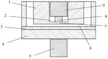
图1为本发明横向剖视结构示意图;Fig. 1 is the schematic diagram of transverse sectional structure of the present invention;
图2为本发明纵向剖视结构示意图;Fig. 2 is a longitudinal sectional structural schematic diagram of the present invention;
图3为本发明关闭流体通道时的结构示意图;Fig. 3 is a schematic structural view of the present invention when closing a fluid channel;
图4为本发明打开流体通道时的结构示意图。Fig. 4 is a schematic diagram of the structure of the present invention when the fluid channel is opened.
图中:1、PDMS芯片,2、阀座,3、PDMS涂层,4、基片,5、电磁铁,6、流体通道,7、PDMS弹性薄膜,8、顶针,9、永磁铁。In the figure: 1. PDMS chip, 2. Valve seat, 3. PDMS coating, 4. Substrate, 5. Electromagnet, 6. Fluid channel, 7. PDMS elastic film, 8. Ejector, 9. Permanent magnet.
具体实施方式Detailed ways
下面结合附图以及具体的实施例进一步说明本发明的技术方案:The technical scheme of the present invention is further described below in conjunction with accompanying drawing and specific embodiment:
如图1、图2所示,本发明提供的集成于微流控芯片上的电磁微阀包括一片永磁铁9,一个电磁铁5、一个顶针8和一个阀座2。所述的微流控芯片包括两层,上层为PDMS芯片1,下层为基片4;基片4上旋涂有PDMS涂层3,该旋涂层厚度为0.5-1mm;阀座2底面为PDMS弹性薄膜7,且该底面为阀座2与所述微流控芯片流体通道6相交的共用壁,该弹性薄膜的厚度可为500μm;阀座的上端与外界相连通;顶针8位于PDMS弹性薄膜7上,对应阀座2中心位置,流体通道6的正上方;永磁铁7放置于阀座2中,对应流体通道6正上方,压在顶针8上方;电磁铁5放置于基片4下方,正对永磁铁9。As shown in FIG. 1 and FIG. 2 , the electromagnetic microvalve integrated on the microfluidic chip provided by the present invention includes a
所述顶针形状可为圆柱或球型,材质可以选择高弹性模量的金属材料,如钢、铁等;其尺寸要视上述微流控芯片流体通道的尺寸而定,较佳的例子为使用圆柱型顶针时,当流体通道宽为80μm,高度为30μm时,可以选择直径为500μm,高度为1-2mm的圆柱座位顶针。The shape of the thimble can be cylindrical or spherical, and the material can be a metal material with a high modulus of elasticity, such as steel, iron, etc.; its size depends on the size of the fluid channel of the above-mentioned microfluidic chip. For cylindrical thimbles, when the fluid channel width is 80 μm and the height is 30 μm, you can choose a cylindrical seating thimble with a diameter of 500 μm and a height of 1-2 mm.
所述永磁铁位于所述阀座中,选用钕铁硼永磁铁;所述永磁铁形状要视阀座形状而定,一般为圆柱或长方体;所述永磁铁底面尺寸要小于阀座0-0.5mm,但是不能为0。The permanent magnet is located in the valve seat, and the NdFeB permanent magnet is selected; the shape of the permanent magnet depends on the shape of the valve seat, generally a cylinder or a cuboid; the bottom surface of the permanent magnet is smaller than the valve seat 0-0.5 mm, but cannot be 0.
本发明提供的电磁微阀通过电磁铁5和永磁体9之间的磁力实现对流体通道的通断控制,如图3所示,当电磁铁5通电时,永磁铁9在磁场的作用下向下运动,永磁铁压迫住顶针8,使顶针8也向下运动,并将压力传递给PDMS弹性薄膜7,促使弹性薄膜7发生相应的弹性变形,该变形使弹性薄膜7紧贴于流体通道6的内壁,导致流体通道6处于完全断路状态;如图4当电磁铁5加反向电压时,永磁铁9在反向磁场的作用下向上运动,抬起顶针8,弹性薄膜7在弹性作用下恢复到初始不受力状态,打开流体通道6,流体通道6处于完全通路状态;因此,通过电磁铁与永磁铁之间的磁力可以精确实现对流体通道的通断控制。The electromagnetic microvalve provided by the present invention realizes the on-off control of the fluid channel through the magnetic force between the
利用本发明提供的电磁微阀实现对流体方向的控制时,可通过设置多个电磁微阀,通过选择性的控制电磁铁电流方向实现对微流控芯片中流体方向的控制。When the electromagnetic microvalve provided by the present invention is used to control the direction of the fluid, multiple electromagnetic microvalves can be provided to selectively control the direction of the electromagnet current to control the direction of the fluid in the microfluidic chip.
上述的电磁微阀中,PDMS弹性薄膜7的厚度可在0-500μm的范围内进行调整;通过控制电磁铁线路中的电流大小,还可以精确控制流道中流体的流速;该电磁微阀中电磁铁和永磁铁位置也可以互换,一样能实现控制通断和流量的结果。In the above-mentioned electromagnetic microvalve, the thickness of the PDMS
以上所述,仅为本发明较佳的具体实施方式,但本发明的保护范围并不局限于此,任何熟悉本技术领域的技术人员在本发明揭露的技术范围内,根据本发明的技术方案及其发明构思加以等同替换或改变,都应涵盖在本发明的保护范围之内。The above is only a preferred embodiment of the present invention, but the scope of protection of the present invention is not limited thereto, any person familiar with the technical field within the technical scope disclosed in the present invention, according to the technical solution of the present invention Any equivalent replacement or change of the inventive concepts thereof shall fall within the protection scope of the present invention.
Claims (6)
Translated fromChinesePriority Applications (1)
| Application Number | Priority Date | Filing Date | Title |
|---|---|---|---|
| CN201310295857.6ACN103335154B (en) | 2013-07-15 | 2013-07-15 | An electromagnetic microvalve integrated on a microfluidic chip |
Applications Claiming Priority (1)
| Application Number | Priority Date | Filing Date | Title |
|---|---|---|---|
| CN201310295857.6ACN103335154B (en) | 2013-07-15 | 2013-07-15 | An electromagnetic microvalve integrated on a microfluidic chip |
Publications (2)
| Publication Number | Publication Date |
|---|---|
| CN103335154Atrue CN103335154A (en) | 2013-10-02 |
| CN103335154B CN103335154B (en) | 2015-07-29 |
Family
ID=49243361
Family Applications (1)
| Application Number | Title | Priority Date | Filing Date |
|---|---|---|---|
| CN201310295857.6AExpired - Fee RelatedCN103335154B (en) | 2013-07-15 | 2013-07-15 | An electromagnetic microvalve integrated on a microfluidic chip |
Country Status (1)
| Country | Link |
|---|---|
| CN (1) | CN103335154B (en) |
Cited By (13)
| Publication number | Priority date | Publication date | Assignee | Title |
|---|---|---|---|---|
| CN104728492A (en)* | 2015-01-27 | 2015-06-24 | 东南大学 | Minitype passive flow regulating valve and manufacturing technique thereof |
| CN105370917A (en)* | 2014-08-19 | 2016-03-02 | 清华大学 | Micro-fluid control valve for micro-fluid control |
| CN106195438A (en)* | 2016-07-22 | 2016-12-07 | 哈尔滨工业大学 | A kind of micro-valve for controlling air pressure |
| CN108223814A (en)* | 2016-12-21 | 2018-06-29 | 无锡源清天木生物科技有限公司 | It is a kind of for the controller for liquid flow of microfluidic control and microfluidic control method |
| CN109114250A (en)* | 2018-09-21 | 2019-01-01 | 昆明理工大学 | A kind of magnetic fluid commutation microvalve device and its application method |
| CN109395649A (en)* | 2018-12-07 | 2019-03-01 | 福州大学 | Paper substrate micro-fluidic micro-mixer and its control method |
| CN110343611A (en)* | 2019-08-14 | 2019-10-18 | 无锡研奥电子科技有限公司 | A kind of micro-fluidic chip |
| CN112481077A (en)* | 2020-12-01 | 2021-03-12 | 北京理工大学 | Microfluidic perfusion culture device and perfusion method thereof |
| CN112762198A (en)* | 2020-12-25 | 2021-05-07 | 京东方科技集团股份有限公司 | A ball valve switch and micro-fluidic chip for micro-fluidic chip |
| CN113511726A (en)* | 2021-05-10 | 2021-10-19 | 深圳市粤昆仑环保实业有限公司 | Rural domestic sewage plant composite bed processing apparatus |
| CN113967486A (en)* | 2020-07-22 | 2022-01-25 | 京东方科技集团股份有限公司 | Centrifugal micro-fluidic chip |
| CN115025827A (en)* | 2022-07-01 | 2022-09-09 | 苏州思迈德生物科技有限公司 | Micro-valve driving device and micro-fluidic chip |
| CN115151630A (en)* | 2020-09-22 | 2022-10-04 | 京东方科技集团股份有限公司 | Nucleic acid extraction microfluidic chip, nucleic acid extraction device and extraction method |
Citations (7)
| Publication number | Priority date | Publication date | Assignee | Title |
|---|---|---|---|---|
| US5065978A (en)* | 1988-04-27 | 1991-11-19 | Dragerwerk Aktiengesellschaft | Valve arrangement of microstructured components |
| CN1867795A (en)* | 2003-08-11 | 2006-11-22 | 加州理工学院 | Microfluidic large scale integration |
| CN101446356A (en)* | 2007-11-26 | 2009-06-03 | 香港理工大学 | Micro valve and device formed by same |
| CN102003560A (en)* | 2010-10-14 | 2011-04-06 | 清华大学 | Normally closed active micro valve for electrically driven shape memory alloy wire |
| CN102057198A (en)* | 2008-06-10 | 2011-05-11 | 罗伯特.博世有限公司 | Compression valve and its manufacturing method |
| CN201884767U (en)* | 2010-07-05 | 2011-06-29 | 博奥生物有限公司 | Bubble micro valve and micro flow control chip based thereon |
| CN102797872A (en)* | 2012-09-01 | 2012-11-28 | 安徽理工大学 | Planar coil driving-type microvalve based on super-magnetostriction film driver |
- 2013
- 2013-07-15CNCN201310295857.6Apatent/CN103335154B/ennot_activeExpired - Fee Related
Patent Citations (7)
| Publication number | Priority date | Publication date | Assignee | Title |
|---|---|---|---|---|
| US5065978A (en)* | 1988-04-27 | 1991-11-19 | Dragerwerk Aktiengesellschaft | Valve arrangement of microstructured components |
| CN1867795A (en)* | 2003-08-11 | 2006-11-22 | 加州理工学院 | Microfluidic large scale integration |
| CN101446356A (en)* | 2007-11-26 | 2009-06-03 | 香港理工大学 | Micro valve and device formed by same |
| CN102057198A (en)* | 2008-06-10 | 2011-05-11 | 罗伯特.博世有限公司 | Compression valve and its manufacturing method |
| CN201884767U (en)* | 2010-07-05 | 2011-06-29 | 博奥生物有限公司 | Bubble micro valve and micro flow control chip based thereon |
| CN102003560A (en)* | 2010-10-14 | 2011-04-06 | 清华大学 | Normally closed active micro valve for electrically driven shape memory alloy wire |
| CN102797872A (en)* | 2012-09-01 | 2012-11-28 | 安徽理工大学 | Planar coil driving-type microvalve based on super-magnetostriction film driver |
Cited By (18)
| Publication number | Priority date | Publication date | Assignee | Title |
|---|---|---|---|---|
| CN105370917A (en)* | 2014-08-19 | 2016-03-02 | 清华大学 | Micro-fluid control valve for micro-fluid control |
| CN105370917B (en)* | 2014-08-19 | 2017-10-31 | 清华大学 | A kind of microfluidic control valve for microfluidic control |
| CN104728492A (en)* | 2015-01-27 | 2015-06-24 | 东南大学 | Minitype passive flow regulating valve and manufacturing technique thereof |
| CN106195438A (en)* | 2016-07-22 | 2016-12-07 | 哈尔滨工业大学 | A kind of micro-valve for controlling air pressure |
| CN108223814A (en)* | 2016-12-21 | 2018-06-29 | 无锡源清天木生物科技有限公司 | It is a kind of for the controller for liquid flow of microfluidic control and microfluidic control method |
| CN108223814B (en)* | 2016-12-21 | 2019-10-15 | 无锡源清天木生物科技有限公司 | A kind of controller for liquid flow and microfluidic control method for microfluidic control |
| CN109114250A (en)* | 2018-09-21 | 2019-01-01 | 昆明理工大学 | A kind of magnetic fluid commutation microvalve device and its application method |
| CN109395649B (en)* | 2018-12-07 | 2023-11-17 | 福州大学 | Paper-based microfluidic micromixer and control method thereof |
| CN109395649A (en)* | 2018-12-07 | 2019-03-01 | 福州大学 | Paper substrate micro-fluidic micro-mixer and its control method |
| CN110343611A (en)* | 2019-08-14 | 2019-10-18 | 无锡研奥电子科技有限公司 | A kind of micro-fluidic chip |
| CN110343611B (en)* | 2019-08-14 | 2022-08-30 | 无锡研奥电子科技有限公司 | Micro-fluidic chip |
| CN113967486A (en)* | 2020-07-22 | 2022-01-25 | 京东方科技集团股份有限公司 | Centrifugal micro-fluidic chip |
| CN115151630A (en)* | 2020-09-22 | 2022-10-04 | 京东方科技集团股份有限公司 | Nucleic acid extraction microfluidic chip, nucleic acid extraction device and extraction method |
| CN112481077A (en)* | 2020-12-01 | 2021-03-12 | 北京理工大学 | Microfluidic perfusion culture device and perfusion method thereof |
| CN112762198A (en)* | 2020-12-25 | 2021-05-07 | 京东方科技集团股份有限公司 | A ball valve switch and micro-fluidic chip for micro-fluidic chip |
| CN113511726A (en)* | 2021-05-10 | 2021-10-19 | 深圳市粤昆仑环保实业有限公司 | Rural domestic sewage plant composite bed processing apparatus |
| CN115025827A (en)* | 2022-07-01 | 2022-09-09 | 苏州思迈德生物科技有限公司 | Micro-valve driving device and micro-fluidic chip |
| CN115025827B (en)* | 2022-07-01 | 2023-11-21 | 苏州思迈德生物科技有限公司 | A microvalve driving device and microfluidic chip |
Also Published As
| Publication number | Publication date |
|---|---|
| CN103335154B (en) | 2015-07-29 |
Similar Documents
| Publication | Publication Date | Title |
|---|---|---|
| CN103335154A (en) | Electromagnetic micro valve integrated on micro-fluidic chip | |
| CN206637105U (en) | A kind of electromagnetic micro valve for micro-fluidic chip | |
| US9618129B2 (en) | Normally closed microvalve and applications of the same | |
| CN203925955U (en) | An electromagnetic micropump based on a microfluidic chip | |
| CN206592627U (en) | A kind of electromagnetic micro valve for being integrated in micro-fluidic chip | |
| CN205824328U (en) | A kind of micro-fluidic chip and be applied to the micro-valve of magnetic cock body of micro-fluidic chip | |
| CN205663974U (en) | Temperature control valve core subassembly, temperature -sensing valve, miniflow way control chip and control system | |
| CN104148124B (en) | A kind of drop formation device for micro-fluidic chip | |
| CN103154529B (en) | Structure of micro device of micro flow path chip series | |
| JP4417334B2 (en) | valve | |
| CN106540760A (en) | A kind of zero leakage magnetic liquid micro-fluidic chip valve body and its method for designing | |
| CN108591609A (en) | A kind of device controlling liquid communication based on magnetic micro-valve | |
| CN110343611B (en) | Micro-fluidic chip | |
| CN103062497A (en) | Intelligent micro valve based on micro-fluidic chip and production method thereof | |
| CN101893112A (en) | A bistable microvalve | |
| CN112283443B (en) | A micro-valve for micro-channel flow control and its control method | |
| US9791068B2 (en) | Lifting gate polydimethylsiloxane microvalves and pumps for microfluidic control | |
| CN105441307B (en) | Unicellular capture chip | |
| CN103062480A (en) | Photo-responsive micro valve based on micro-fluidic chip and production method thereof | |
| CN106195438B (en) | A kind of micro-valve for control pressure | |
| CN209115721U (en) | A kind of magnetic fluid commutation microvalve device | |
| CN109759153A (en) | Electrowetting valve for capillary action microfluidic chip and control method thereof | |
| CN217328759U (en) | A microfluidic control device | |
| CN206449301U (en) | A kind of zero leakage magnetic liquid micro-fluidic chip valve body | |
| CN110410575A (en) | A mobile electromagnetically driven microvalve for microfluidic chips |
Legal Events
| Date | Code | Title | Description |
|---|---|---|---|
| C06 | Publication | ||
| PB01 | Publication | ||
| C10 | Entry into substantive examination | ||
| SE01 | Entry into force of request for substantive examination | ||
| C14 | Grant of patent or utility model | ||
| GR01 | Patent grant | ||
| CF01 | Termination of patent right due to non-payment of annual fee | Granted publication date:20150729 Termination date:20160715 | |
| CF01 | Termination of patent right due to non-payment of annual fee |